1
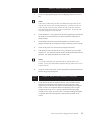
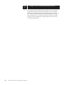
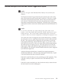
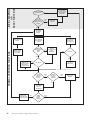
Installation & Operation Manual
Electronic Pinsetter
Trigger/Control
System
September 2005 / 12-902262-000
Electronic Pinsetter Trigger/Control System Installation & Operation Manual
U.S. Patent No. 5,429,554
© September 2005 by the Brunswick Bowling and Billiards Corporation. All rights reserved.
Past Revisions: August 1995
Model A, A-2, and GS-Series are registered trademarks of the Brunswick Bowling and Billiards Corporation.
Reorder Part No. 12-902262-000
Confidential proprietary information. All information contained in this document is subject to change without notice.
Notice: If available, updates to this manual can be found on-line at www.brunswickbowling.com
Brunswick Bowling & Billiards Corporation
525 West Laketon Avenue
P.O. Box 329
Muskegon, MI 49443-0329
U.S.A.
231.725.3300
2
Electronic Pinsetter Trigger/Control System
SAFETY
Throughout this publication, “Warnings”, and “Cautions” (accompanied by one of
the International HAZARD Symbols) are used to alert the mechanic to special
instructions concerning a particular service or operation that may be hazardous if
performed incorrectly or carelessly. They are defined below. OBSERVE
AND READ THEM CAREFULLY!
These “Safety Alerts” alone cannot eliminate the hazards that they signal. Strict
compliance to these special instructions when performing the service, plus
training and “Common Sense” operation are major accident prevention measures.
NOTE or IMPORTANT!:
Will designate significant informational notes.
WARNING!
Will designate a mechanical or nonelectrical alert which could potentially cause personal injury or death.
WARNING!
Will designate electrical alerts which could potentially cause personal injury or death.
CAUTION!
Will designate a mechanical or nonelectrical alert which could potentially cause product damage.
Will designate grounding alerts.
Electronic Pinsetter Trigger/Control System
3
SAFETY NOTICE TO USERS OF THIS MANUAL
This manual has been written and published by the Service Department of
Brunswick Bowling and Billiards to aid the reader when servicing or installing the
products described.
It is assumed that these personnel are familiar with, and have been trained in, the
servicing or installation procedures of these products, which includes the use of
common mechanic’s hand tools and any special Brunswick or recommended
tools from other suppliers.
We could not possibly know of and advise the reader of all conceivable procedures by which a service might be performed and of the possible hazards and/or
results of each method. We have not attempted any such wide evaluation.
Therefore, anyone who uses a service procedure and/or tool, which is not
recommended by Brunswick, must first completely satisfy himself that neither his
nor the products safety will be endangered by the service procedure selected.
All information, illustrations and specifications contained in this manual are based
on the latest product information available at the time of publication.
It should be kept in mind, while working on the product, that the electrical system
is capable of violent and damaging short circuits or severe electrical shocks.
When performing any work where electrical terminals could possibly be
grounded or touched by the mechanic, the power to the product should be
disconnected prior to servicing and remain disconnected until servicing is complete.
4
Electronic Pinsetter Trigger/Control System
Table of Contents
Introduction .......................................................................................................... 6
Electronic Ball Detect ......................................................................... 6
Microprocessor Control Board ........................................................... 6
Rake Down Microswitch Assembly .................................................... 7
Preparation ........................................................................................................... 8
Tools Required ................................................................................... 9
Installation of the Control Board ....................................................................... 10
Installation of the Safety Shut-off Connections ................................................. 13
Installation of Electronic Ball Detect Assembly ................................................ 17
Special Installation Instructions for Pinsetters with Brunswick
Automatic Scoring and Standard Take Data Relay Kit ....................................... 19
Special Installation Instructions for Pinsetters with Automatic Scoring
and Japanese Take Data Relay Kit ..................................................................... 21
Ball Detect Alignment and System Check .......................................................... 23
Troubleshooting .................................................................................................. 25
Functional Description of the Electronic Pinsetter Trigger/Control System ..... 29
Electronic Pinsetter Trigger/Control System
5
Introduction
The new Brunswick Electronic Trigger/Control System, U.S. Patent No.
5,429,554, controls the cycle functions of the Brunswick A-2 and A-2 converted
(must have electrical time delay module and A-2 style pit cushion with quick rake
drop [shot gun]) pinsetting machines. Its primary function is to cause the
pinsetter to cycle after a bowling ball is delivered and enters the pit end. The
need for this new system arises from the increase of slowly delivered balls
(bumper bowl) and worn or misadjusted parts which do not allow a consistent
mechanical triggering of the pinsetter. It accomplishes this function along with
some key safety features with the three included components described as
follows:
NOTE:
This system does not work on any automatic scorer except Brunswick. For
additional parts and instructions for installing this system onto a Model A
Pinsetter (pinsetters with no electrical time delay module and no A-2 style
pit cushion with quick rake drop [shotgun]), order supplement package
part no. 12-860811-000. For additional parts and instructions for installing this system onto a cable triggered, Jet Back pinsetter system (pinsetters
with no electrical time delay module, but already have the A-2 style pit
cushion with a quick rake drop [shotgun]), order supplemental package
part no. 12-862898-000.
Electronic Ball Detect
This reliable, dual output, infrared ball detect module is mounted ahead of the
kickback, below the dropsweep, and sends a signal to the new control board.
Microprocessor Control Board
The new microprocessor control board replaces the existing time delay module in
the electrical control box of the pinsetter. It functions as the “brain” of the new
Electronic Pinsetter Trigger/Control System by accepting input from the electronic ball detect module and rake position switches, and adjusting the time
delays, cycle, and scoring functions to match the ABC approved, original
Brunswick designed systems. It also offers some enhanced features such as an
automatic switch back to mechanical triggering of the pinsetter in the absence of
an electronic ball detect signal. Once the cycle has started, the reset button is
locked out to prevent “banana stops.” Another important feature of the microprocessor control board is the safety shut-off system which shuts off the
pinsetter motor if the rake drop is blocked.
6
Electronic Pinsetter Trigger/Control System
Rake Down Microswitch Assembly
The Rake Down Microswitch Assembly is attached to the center cross brace
with a trigger clip on the rake lift shaft. It senses when the rake has dropped
completely and connects to the microprocessor control board to complete the
safety shut-off system.
Electronic Pinsetter Trigger/Control System
7
Preparation
Make sure all parts listed below are included in the supplied kit. This kit (part no.
12-862584-400) contains the necessary parts to equip one lane pair of two
pinsetters with the Electronic Pinsetter Trigger/Control System.
Qty.
Part Number
2
12-862918-400
Microprocessor Control Board
Description
1
57-214921-091
Electronic Ball Detect Assembly
(Includes 2 ball detects mounted on a
bracket.)
2
12-752396-000
Rake Down Microswitch Assembly
(Includes U-bolt, trigger clip, and wire
harness.)
2
12-752401-000
Safety Lockout Wire Harness (18 in.
long with ring terminal and butt splice.)
2
12-752402-000
Ball Detect Cable (12 ft. long.)
2
12-752403-000
Scorer Wire Harness (Red single wire.)
1
12-862895-000
Hardware Package
1
17-600702-000
Dual Reflector (3 in. diameter,
reference NOTE below.)
1
12-902262-000
Installation and Operation Manual
NOTE:
For each installation, the first lane pair installed and any post row or aisle
way will require an additional reflector not supplied with this kit. (Contact
your Brunswick service parts supplier for additional reflector assemblies,
part no. 17-600702-000. Use only Brunswick reflectors, as other types are
not designed for this application and will not perform as well.)
8
Electronic Pinsetter Trigger/Control System
Tools Required
1.
2.
3.
4.
5.
6.
7.
8.
9.
10.
11.
12.
13.
14.
Screw Driver - Phillips (For Electrical Box Cover Removal)
Socket (7/16") and Drive Ratchet (3/8") or Nut Driver (7/16")
Screw Starter (Holder) - Slotted
Screw Driver - Small #1 Phillips
Crimpers
Wire Stripper
Safety Glasses
Tape Measure
Electric Drill
Drill Bit (7/64" or 3/32" dia.)
Drill Bit (3/16" dia.)
Drill Bit (3/4" or 7/8" dia.) or Greenlee Knockout Punch
(Available from Electrician Supply)
Magnet
Clean Dry Cloth
Electronic Pinsetter Trigger/Control System
9
Installation of the Control Board
WARNING!
Be sure the circuit breaker is off and disconnect the high voltage input power cord
before removing the cover of the pinsetter electrical control box. Lethal voltages are
present!
1.
Turn off the main circuit breaker and disconnect the high voltage input
power cord. Also remove cannon plug CP3 from the top of the pinsetter
electrical control box.
2.
Remove the cover from the pinsetter electrical control box.
3.
A hole will need to be drilled in the top of the pinsetter electrical control
box for routing wires to the ball detect, rake down microswitch, etc.
Locate an area on top of the electrical box above the motor contactor
with proper clearance. Reference the figure titled Control Board
Mounting Diagram. Center punch this location. Place a cloth inside
the box to keep the metal drilling shavings off the electrical components.
Drill the 3/4" or 7/8" diameter hole or use a Greenlee knockout punch
and fasten the supplied cable (Romex) clamp through the hole.
NOTE:
If sufficient space is available in existing cable clamp, installing a new
cable clamp may not be necessary. Check cable clamp for sharp edges
which can cut through wire insulation and remove sharp edges and/or
wrap cable with protective layer of electrical tape where it passes through
cable clamp.
4.
Without disconnecting the wires, unscrew the existing time delay module
from the bottom of the box.
CAUTION!
To reduce the risk of static discharge damage to the control board, leave the board in
its protective bag until installed and always touch a grounded surface before handling
the control board.
5.
10
If the new control board mounting spacers do not match the holes in the
control box where the old time delay module was removed, it may be
necessary to move the one mounting spacer to the other hole in the
control board. If this does not match, drill a new 3/16" diameter hole in
the control box.
Electronic Pinsetter Trigger/Control System
6.
Brush or use a magnet to remove the drilling shavings from the bottom
of the box.
7.
Screw the new control board to the electrical box with supplied hardware as shown in the figure titled Control Board Mounting Diagram.
NOTE:
The flat washers are used to sandwich the slots in the electrical box with a
lockwasher under the screw head. If your electrical box has holes instead
of slots, the flat washers are not necessary.
8.
Transfer the wires from the old time delay module in the same positions
onto the new control board. Transfer the wires one by one until you
have transferred the wires from all eight terminals (#13 to #20).
NOTE:
If there are multiple wires on one terminal, transfer them just as if they
were a single wire. Terminal #15 (second ball signal) may be empty on
some pinsetters.
NOTE:
If your old time delay modules had screw terminals, it will be necessary to
remove and discard the spade terminals from the screw terminals and
attach the wires directly onto the screw terminals.
Electronic Pinsetter Trigger/Control System
11
Control Board Mounting Diagram
12
Electronic Pinsetter Trigger/Control System
Installation of the Safety Shut-off Connections
1.
The new Electronic Trigger/Control System uses the existing rake
trigger microswitch as a “rake up” switch. It is important that this
switch be adjusted for a 1/16" gap between the microswitch plunger and
the actuator lever when the rake is in the raised position. Reference the
figure titled Rake Position Safety Switch Locations and Adjustments
and Adjustment #6 in the Pinsetter Service Manual, part no. 12752828-000. Adjust to a 1/16" gap rather than a 1/16" gap minimum as
noted in the service manual. Remove the normally closed terminal
from the existing rake trigger microswitch and tape it out of the
way. Reference the figure titled Rake Position Safety Switch Locations and Adjustments. The N.C. wire is usually the bottom terminal on
the switch. If there are two microswitches, remove the N.C. wire from
the outside or right-most switch.
2.
Install the Rake Down Microswitch Assembly with the U-bolt clamped
around the center cross brace. The Rake Down Microswitch Assembly
can be installed on either side of the electrical control box, but make sure
the switch is positioned on the rear side of the pinsetter. Reference the
figure titled Rake Position Safety Switch Locations and Adjustments.
Rotate the switch assembly so the end of the actuator lever just clears
the rake lift shaft by 1/16". Tighten the U-bolt nuts.
3.
Manually trip the rake trip-latch to lower the rake. Wear your safety
glasses and install the clip onto the rake lift shaft so its longer leg
just contacts the actuator lever. Rotate the clip until it raises the
actuator lever far enough to open the switch (an audible click can be
heard when the switch opens). Then rotate the clip slightly farther until
the actuator lever just clears the switch plunger (not more than a 1/16"
gap). Reference the figure titled Rake Position Safety Switch Locations and Adjustments.
NOTE:
This gap will increase as the rake starts to sweep.
4.
The rake down switch wire harness (with two spade receptacles) should
be connected to the N.C. and “Com” terminals of the new microswitch.
Route the wire harness through the cable clamp on top of the electrical
control box and connect to the new control board. Reference the figure
titled Control Board Location Diagram for proper connecting location.
Secure wire harness away from moving parts as required.
Electronic Pinsetter Trigger/Control System
13
ROTATE AT U-BOLT SO END OF
ACTUATOR LEVER JUST CLEARS
RAKE LIFT SHAFT AS IT ROTATES
PINSETTER ELECTRICAL
CONTROL BOX
RAKE LIFT SHAFT
1/16" GAP WITH RAKE DOWN
NC
COM
TRIGGERING CLIP
CENTER CROSS BRACE
U-BOLT
RAKE DOWN
MICROSWITCH
ASSEMBLY
POSITIONED ON
REAR SIDE
OF PINSETTER
ACTUATOR LEVER
RAKE SWEEP SHAFT
NOTE LONGER LEG
OF TRIGGERING
CLIP AGAINST
ACTUATOR LEVER
RAKE DOWN MICROSWITCH POSITION
(VIEW FROM RIGHT SIDE OF PINSETTER (10-PIN SIDE))
1/16" GAP WITH RAKE UP
POSSIBLE LOCATION OF
RAKE DOWN SWITCH
IF ELECTRICAL CONTROL BOX
IS ON REAR OF PINSETTER
PINSETTER
ELECTRICAL CONTROL BOX
RAKE UP MICROSWITCH
(PREVIOUSLY RAKE
TRIGGER SWITCH)
REMOVE WIRE FROM
N.C. TERMINAL
TRIGGERING CLIP
NC
RAKE LIFT SHAFT
ACTUATOR LEVER
RAKE UP MICROSWITCH POSITION
(VIEW FROM LEFT SIDE OF PINSETTER (7-PIN SIDE))
Rake Position Safety Switch Locations and Adjustments
14
Electronic Pinsetter Trigger/Control System
Control Board Location Diagram
5.
Remove wire #20 from terminal #5 of the low voltage terminal strip that
is routed from the wire channel.
NOTE:
Reference Pinsetter Service Manual, part no. 12-752828-000, pages 1-84
through 1-91 for wiring diagrams. Wire #20 is connected to the rear
mechanic's switch SW1. Make sure not to connect to the wires from any
bypass switch. Do not count the mounting screws as the first terminal.
Cut off the ring terminal, strip 1/4" of insulation from the wire, and crimp
the butt splice from the Safety Lockout Wire Harness (18 in. long
harness) to the existing stripped wire. Reference the figure titled
Connection of Safety Lockout Wire Harness.
6.
The remaining wire from the Safety Lockout Wire Harness has a #6
ring terminal on it. Connect this ring terminal back onto terminal #5 of
the low voltage terminal strip in place of the wire removed in the previous step. Reference the figure titled Connection of Safety Lockout
Wire Harness.
Electronic Pinsetter Trigger/Control System
15
7.
Route the connector end of the Safety Lockout Wire Harness to the new
control board and connect to location shown in the figure titled Control
Board Location Diagram.
8.
Reconnect cannon plug CP3 onto the top of the pinsetter electrical
control box.
NOTE: DO NOT COUNT
MOUNTING SCREWS AS
FIRST TERMINAL
SAFETY LOCKOUT
WIRE HARNESS
LOW VOLTAGE
TERMINAL STRIP
BUTT SPLICE
RING
TERMINAL
WIRE CHANNEL
WIRE #20
(FROM REAR MECHANIC'S
SWITCH SW1)
Connection of Safety Lockout Wire Harness
16
Electronic Pinsetter Trigger/Control System
CUT OFF RING
TERMINAL AND CONNECT
TO BUTT SPLICE
Installation of Electronic Ball Detect Assembly
1.
Connect the 12 ft. ball detect cable to the location indicated on the new
control board. Reference the figure titled Control Board Location
Diagram. Route the cable along the walkway side of the pinsetter,
down to the front edge of the kickback plate. Make sure the cable will
not interfere with any moving parts of the ball return or rake.
2.
Install the ball detect bracket, with the two mounted ball detects just
ahead of the kickback, below the dropsweep. Drill 7/64" or 3/32"
diameter pilot holes and attach using the wood screws provided. Reference the figure titled Ball Detect Installation and Adjustment. The
assembly should be mounted level across the lane and square with the
end of the lane. The ideal location for the detector beam is 8" to 20" in
front of the head pin. The sweep of the rake does not cause problems
when it breaks the detector beam. Check that the mounting site (fill
block) is not loose and secure as required.
NOTE:
If scorer ball detect is mounted in same area, allow 4" between detectors.
3.
Install the safety decals in visible locations just below the ball detects.
Reference the figure titled Ball Detect Installation and Adjustment. If
safety decals become lost or damaged, reorder part no. 47-082592-000.
4.
Mount the reflector opposite the ball detect assembly. Drill 7/64" or
3/32" diameter pilot holes and attach using the wood screws provided.
The end of the gutter is a good reference to insure that the detector and
reflector are mounted squarely to the lane. Reference the figure titled
Ball Detect Installation and Adjustment. Make sure that the top of
the reflector is not above the height of the ball as it passes in the gutters.
NOTE:
For each installation, the first lane pair installed and any post row or aisle
way will require an additional reflector not supplied with this kit. (Contact
your Brunswick service parts supplier for additional reflector assemblies,
part no. 17-600702-000. Use only Brunswick reflectors as other types are
not designed for this application and will not perform as well.)
5.
Connect the ball detect cable into the module. Again, make sure the
cable is not going to interfere with the ball return or rake as it sweeps.
Secure the cable with tie wraps.
6.
The ball detect and reflectors will be aligned after power is turned back
on, as described in the Ball Detect Alignment and System Check
section of this manual.
Electronic Pinsetter Trigger/Control System
17
VERTICAL
ADJUSTING SCREW
RED LED
TRANSMITTER
RECEIVER
HORIZONTAL
ADJUSTING SCREWS
NOTE: KEEP ADJUSTING SCREWS
TIGHT ENOUGH TO PULL
SENSOR CLOSE TO HOUSING
OPENING, WHICH KEEPS
INTERNAL SPRINGS TENSIONED.
FRONT VIEW OF BALL DETECT
KICKBACKS
MOUNT BALL DETECT BRACKET
IN FRONT OF KICKBACK
(BELOW DROPSWEEP)
SAFETY DECALS
FILL BLOCKS
GUTTER
0"
8" - 2
CENTER OF
BALL DETECT
BEAM
REFLECTOR
Ball Detect Installation and Adjustment
18
Electronic Pinsetter Trigger/Control System
Special Installation Instructions for Pinsetters with Brunswick Automatic Scoring
and Standard Take Data Relay Kit
NOTE:
The following steps do not apply if you do not have the Take Data Relay
Kit installed (normally located in the lower right corner of the electrical
control box as facing the rear of the machine). You may consider adding
the Take Data Relay Kit (part no. 57-860109-000) if you experience
problems with scoring accuracy.
NOTE:
If you are installing the Take Data Relay Kit at the same time as the new
Electronic Trigger/Control System, modify the instructions as follows:
-
Do not cut wire #61 as stated in step 7 of the separate Take Data
Relay Kit instructions.
-
Connect the red wire from the Take Data Relay Kit to the scorer
wire harness as in step 1 below.
-
Tape the black wire from the Take Data Relay Kit to the inside of
the electrical box as it is unused.
1.
Find the heavy red wire from the Take Data Relay Kit that is spliced
into wire #61 from CP2. Cut the splice off and strip 1/4" of insulation
off both the red wire and wire #61. Crimp the red wire from the Take
Data Relay Kit, to the provided red wire of the scorer harness, using the
butt splice on the harness. Reference the figure titled Connection of
Scorer and Standard Take Data Relay Kit Wires.
2.
Cut the heavy black wire approximately 3" from the Take Data Relay
Kit. Tape the 3" end to the inside of the electrical box (not used). Strip
1/4" of insulation off the long end of the black wire. Reference the
figure titled Connection of Scorer and Standard Take Data Relay Kit
Wires.
3.
Connect the black wire that was stripped in step 2 and wire #61 in step 1
together with the provided butt splice.
NOTE:
This effectively reconnects wire #61 that connects the ball rack cycle button
from the cannon plug (CP2) to Y2. (Reference the Pinsetter Service Manual,
part no. 12-752828-000, pages 1-69 through 1-74.)
4.
Route the red scorer wire harness to the new control board and connect
to the location indicated in the figure titled Control Board Location
Diagram.
Electronic Pinsetter Trigger/Control System
19
HIGH VOLTAGE
TERMINAL STRIP
CUT SPLICE BETWEEN
RED WIRE AND WIRE #61.
RECONNECT LONG END OF
BLACK WIRE TO WIRE #61
FROM CP2
CP2
BLACK
WIRE #61
WIRE #55
RECONNECT
RED WIRE TO
NEW WIRE
SCORER
HARNESS
LOW VOLTAGE
TERMINAL STRIP
GREEN
RED SCORER
WIRE HARNESS
RED
TERMINAL
#17
TERMINAL
#14
Connection of Scorer and Standard Take Data Relay Kit Wires
20
Electronic Pinsetter Trigger/Control System
CUT BLACK WIRE
HERE AND TAPE
OFF SHORT END
SCORER
TAKE DATA
RELAY
Special Installation Instructions for Pinsetters with Automatic Scoring
and Japanese Take Data Relay Kit
For the following steps, reference the figure titled Connection of Scorer and
Japanese Take Data Relay Kit Wires.
1.
Find the red wire from the Take Data Relay Kit that is spliced into wire
#61 from the ball rack reset switch. Cut the splice off and strip 1/4" of
insulation off both the red wire and wire #61.
2.
Find the gray wire from the Take Data Relay Kit that is spliced into wire
#61 right next to the wire nut which connects wires #52, #55, and #60.
Cut the splice off and strip 1/4" of insulation off both the gray wire and
wire #61.
NOTE:
Wire #52 should already be disconnected from the trigger switch.
3.
Reconnect both ends of wire #61 together with the provided butt splice.
4.
Find the provided red scorer wire harness and insert the red and gray
wires from the Take Data Relay Kit into the butt splice on the scorer
harness. Crimp the butt splice securely. Connect the spade terminal of
the red scorer wire harness to the control board location labeled “Score”
as indicated in the figure titled Control Board Location Diagram.
5.
Remove the white wire from the Take Data Relay Kit where it is
attached to terminal #18 of the control board. Connect this white wire
together with the black wire from the Take Data Relay on terminal #14
of the control board.
Electronic Pinsetter Trigger/Control System
21
CUT SPLICE BETWEEN
RED WIRE AND WIRE #61
RECONNECT ENDS OF
WIRE #61 WITH BUTT SPLICE
CP2
HIGH VOLTAGE
TERMINAL STRIP
CUT SPLICE BETWEEN
GRAY WIRE AND WIRE #61
WIRE #61
WIRE #55
RECONNECT
GRAY AND RED WIRES
TO NEW SCORER
WIRE HARNESS
RED SCORER
WIRE HARNESS
AY
BLACK
LOW VOLTAGE
TERMINAL STRIP
GR
WHITE
RED
REMOVE WHITE WIRE
FROM TERMINAL #18
TERMINAL
#14
TERMINAL
#17
RECONNECT WHITE WIRE
TO TERMINAL #14
Connection of Scorer and Japanese Take Data Relay Kit Wires
22
Electronic Pinsetter Trigger/Control System
SCORER
TAKE DATA
RELAY
Ball Detect Alignment and System Check
1.
Reconnect the high voltage input power cord and turn the circuit breaker
on. The motor should start; if not, check the rake down microswitch to
see that the actuator lever just clears the switch plunger when the rake
is down. Check that there is a 1/16" gap between the rake triggering
microswitch and the actuator lever when the rake is up. Reference the
figure titled Rake Position Safety Switch Locations and Adjustments.
2.
Check the ball detect to make sure it is aligned with the reflector as
follows:
WARNING!
The motor must be disconnected while making any adjustments to the ball detect,
because the ball detect can trigger the pinsetter.
3.
a.
Check the face of the ball detect and make sure it is parallel with
the face of the ball detect's housing. Check the reflector to see if
it is mounted securely and parallel to the ball detect. Clean the
transmitter, receiver, and reflector with a clean dry cloth before
and after adjusting.
b.
Cover the reflector with a dark, nonreflective object. The red
LED should be lit indicating the beam is not reflecting.
c.
Hold an unmounted reflector in your hand and move it above,
below, and around the beam zone to find the edges of the zone
where the LED just goes out.
d.
Using the vertical and horizontal adjusting screws (reference the
figure titled Ball Detect Installation and Adjustment), move the
beam zone until it is centered around the mounted reflector.
e.
To verify that the beam is centered, cover one half of the reflector with a dark card. The red LED should not light until more
than one half of the reflector is covered. Repeat this procedure
by covering the top half, the bottom half, the left half, and the right
half. The beam is centered only when the red LED stays off
while covering an equal amount of the reflector from all four
positions.
f.
Turn the circuit breaker off. Plug in the motor. Turn the circuit
breaker on.
Roll a ball past the ball detect to verify correct operation. (It is suggested trying both gutters and center of lane.)
Electronic Pinsetter Trigger/Control System
23
4.
Manually trip the rake at the rake trip-latch (shotgun) so it lowers
without an electronic ball detect signal to verify that the automatic
backup system operates.
5.
Press the cycle buttons on the ball return rack and the rear of the
pinsetter to verify correct operation.
6.
Check the safety shut-off system by placing a box or other object under
the rake to prevent it from dropping completely. Block the rake in a
way that it can slide off the object easily if the rake starts to sweep.
Trip the rake mechanically at the rake trip-latch (shotgun) without
triggering the ball detect. (If the ball detect beam is interrupted for a
long period of time, as with the object blocking the rake, the pinsetter will
not be cycled by the ball detect until the beam is again reflected back to
the ball detect.) The motor should shut off before the start of the cycle.
If the motor does not shut off, check the adjustment of the rake up and
rake down microswitches.
NOTE:
When the safety system shuts off the pinsetter motor, it turns on the indicator light on the control board until the system is reset. Reference the figure
titled Control Board Location Diagram. You can only reset the system by
turning off the main breaker, waiting ten seconds, and then turning it back
on.
WARNING!
Do not cycle the pinsetter by manually lifting the clutch cycle solenoid plunger or
pushing the stop arm out from under the clutch lever, as this is not a normal condition
and this bypasses the safety shut-off system.
24
7.
After the pinsetter is ready for a new cycle, block the rake as in step 6
above. Check the other part of the safety shut-off system by pressing
the reset button or break the ball detect beam so the pinsetter starts to
cycle before the rake is tripped and lowers the rake with the rake lift
cam. The motor should shut off before the rake starts sweeping.
8.
If all checks are ok, turn the circuit breaker off, make sure the correct
wires are routed correctly, and replace the electrical box cover. If all
checks are not ok, recheck the installation instructions and refer to the
following Troubleshooting section.
9.
Attach the supplied adhesive-backed instructional label onto the outside
of the electrical control box cover to indicate that the pinsetter is now
controlled by the Electronic Pinsetter Trigger/Control System. Basic
troubleshooting steps are also indicated on this label.
Electronic Pinsetter Trigger/Control System
Troubleshooting
Proper troubleshooting of any system requires a clear understanding of the
operating sequence of the system. A functional flow chart is provided in the
figure titled Functional Flow Chart, along with a description of the Electronic
Pinsetter Trigger/Control System operation. It is helpful to understand that this
system checks the position of the rake at different times, and may either add
extra time delays or shut off the pinsetter motor if the rake is not completely
down at proper times.
The following troubleshooting guide gives the most common problems and
solutions:
Solution
No.
1
Problem 1: Pinsetter Will Not Cycle
Press the reset button. If it still does not cycle, turn off the circuit breaker,
wait ten seconds, then turn it back on to reset the microprocessor.
NOTE:
The reset button will not cycle the pinsetter if the rake is not up. The
only exception to this occurs when the rake is dropped while the pinsetter
is turned off. The reset button will recycle the pinsetter in this situation,
but there will be a 30 second delay from the time the rake is dropped, to
when the pinsetter will recycle. Before respotting pins, it is suggested to
shut off the circuit breaker instead of the mechanic’s switch so the
pinsetter will recycle without delay when the circuit breaker is turned
back on.
2
Check that the ball detect is adjusted correctly. If the ball detect LED is on
when nothing is blocking the beam, it needs to be readjusted.
NOTE:
If the ball detect beam is interrupted for a long period of time or if it is
misaligned so the LED is constantly on, the pinsetter will not cycle until
the beam is again reflected back to the ball detect. If there is no time to
realign the ball detect or you suspect that it is damaged, temporarily
disconnect the detector cable. The control board will then function as a
normal time delay module triggered by the rake drop until the ball detect
problem can be corrected.
WARNING!
The motor must be disconnected while making any adjustments to the ball detect,
because the ball detect can trigger the pinsetter.
3
Check that the safety shut-off indicator on the on the control board is not
on. If this indicator is on and the pinsetter motor was not shut off, reference Problem 2.
4
Check that the fuse on the control board is not blown. If it is, check for a
short in the 24 volt system (reset button, trigger switch, mechanic’s switch,
etc.) and repair. Replace fuse with part no. 11-685053-000, 1 amp, fast blow,
5 mm x 20 mm fuse.
Electronic Pinsetter Trigger/Control System
25
Solution
No.
5
Problem 1: Pinsetter Will Not Cycle
(continued)
Check for damaged ball detect, damaged cable, or poor connection at either
end of cable. Problems may not be obvious. Best check is to disconnect
ball detect cable at control board and reset the system by turning the circuit
breaker off, then on again. If system then cycles with reset button or rake
drop, you have verified the main control board is working properly. Check
and replace ball detect or cable as necessary.
WARNING!
Turn off the circuit breaker and disconnect the high voltage input power cord before
touching anything inside electrical control box. Lethal voltages are present!
NOTE:
If spare control board is not available, a standard time delay module can
be installed as a temporary solution. A jumper (solid 22 gauge wire
stripped 1/4" at both ends) will need to be installed in the safety lockout
wire harness connector and taped off until a replacement control board is
installed.
Solution
No.
26
Problem 2: Safety Shut-off System Does Not Shut Off the
Pinsetter Motor When the Rake is Blocked
1
Check for a 1/16" gap between rake triggering microswitch and the actuator
lever when rake is in the raised position.
2
Check that the rake down microswitch actuator lever just clears the switch
plunger when the rake is completely lowered, but has not started sweeping.
3
Make sure the safety lockout wire harness is hooked in series with the rear
mechanic's switch SW1. This should be wire #20. Do not connect to any
bypass switch. If the safety shut-off indicator is on but the pinsetter motor
is not off, pull the safety lockout wire harness connection off the control
board. If this shuts off the motor, the wiring is correct and the microprocessor control board may be faulty. If this does not shut off the motor, the
lockout wire is still not connected in series with the rear mechanic's switch
SW1. Reconnect the safety lockout wire harness to the control board and
trace the rear mechanic's switch SW1 wire with a continuity tester.
4
If the pinsetter motor cycles on and off when the rake is blocked, check that
the control board has power (24 volts A/C) across terminals #13 and #14
when the circuit breaker is on and the mechanic's switch is off. Make sure
wire #54 is wired correctly on the motor start relay terminals.
Electronic Pinsetter Trigger/Control System
Solution
No.
1
Problem 3: Pinsetter Motor Shuts Off
Check for anything blocking the rake from dropping and correct as necessary.
NOTE:
If the rake is held between the fully raised and lowered position by the
rake lift cam (such as after clearing a deck jam), it will be necessary to
rotate the gear box drive pulley to move the rake to the fully raised or
lowered position before turning on the circuit breaker. Or trip the rake
trip-latch (shotgun) to lower the rake.
2
Check that there is a 1/16" gap between the rake triggering microswitch and
the actuator lever when the rake is in the raised position (especially on
Model A units).
3
Check that the rake down microswitch actuator lever clears the switch
plunger when the rake is completely lowered, but has not started sweeping.
4
Check for any loose wire connections or faulty microswitches.
5
If the pinsetter locks-out when the reset or cycle button is pressed, make
sure the N.C. wire of the microswitch on the rake shaft is disconnected and
taped off. It is usually the bottom wire on the switch.
NOTE:
To reset the system after any safety shut-off, turn off the main circuit
breaker, correct the problem that caused the shut-off, and turn the circuit
breaker back on.
6
Solution
No.
1
Check for a deck or turret jam, or some other problem beyond the Electronic
Pinsetter Trigger/Control System.
Problem 4: Pinsetter Cycles Continuously or Unexpectedly
Check that the ball detect is aligned correctly. Also, check that nearby
detectors are aligned and scorer detectors are spaced at least 4" from
trigger detector. If the ball detect LED is on when nothing is blocking the
beam, it needs to be readjusted. Make sure adjusting screws are tight
enough to pull sensor close to opening, which keeps internal springs
tensioned. Also, check for loose sensor or reflector mounting and tighten
as required. Disconnect the ball detect cable until the problem can be
solved.
Electronic Pinsetter Trigger/Control System
27
Solution
No.
1
28
Electronic Pinsetter Trigger/Control System
Problem 5: Scorer or Take Data Relay Functions Incorrectly
Test operation of the Take Data Relay by actuating the scorer ball detect
and then pressing the reset button on the ball rack. The scorer should
display the score immediately and not wait until the pinsetter reaches 44º or
144º. If this test is failed, recheck the Take Data Relay for proper wiring,
proper diode function, etc., and repair or replace as required. If constant
scanning of the Take Data Relay is a problem, disconnect the red scorer
wire from the control board.
Functional Description of the Electronic Pinsetter Trigger/Control System
NOTE:
Reference the figure titled Functional Flow Chart for the functional flow
diagram.
The Electronic Pinsetter Trigger/Control System operation starts with a safety
shut-off check after the main circuit breaker is turned on. If the rake is caught
between the raised and lowered positions, the 24 volts to the motor start relay
coil is shut off. This disables the motor start relay and the motor contactor,
which shuts off the pinsetter motor immediately. When the safety system shuts
off the pinsetter motor, it turns on the indicator light on the control board until it is
reset.
NOTE:
To reset the system after any safety shut-off, turn off the main circuit
breaker, correct the problem that caused the shut-off, and turn the circuit
breaker back on. The circuit breaker should remain off for at least five
seconds to allow the electrical components to discharge and properly reset.
The system next waits to be triggered in one of three different ways. Normally,
the system first receives a signal from the ball detect as a ball is delivered down
the lane. The system can also be triggered by the reset button or by the rake
being tripped mechanically without a ball detect signal. As you can see in the
figure titled Functional Flow Chart, the system follows different paths depending on the first type of trigger it receives. After the system receives the first
trigger signal, it ignores any additional trigger signal until the current cycle has
been completed. We will follow a normal situation where the system is triggered
by the ball detect signal first.
After the ball triggers the ball detect, it normally has enough momentum to
mechanically trip the rake. If the rake drop is not tripped mechanically, a signal
is sent to the optional rake drop solenoid (if installed).
If the ball is on the first ball cycle, the system delays per ABC regulation. Then,
if the rake is still up, a signal is sent to the scorer Take Data Relay Kit (if
installed).
If the ball is on the second ball cycle, the electrical time delay is shorter because
the deck doesn't lower on the standing pins.
Electronic Pinsetter Trigger/Control System
29
INITIAL STARTING
OR
RESET FUNCTIONS
WAIT FOR
MANUAL RESET
OF CIRCUIT
BREAKER
HIGH VOLTAGE
POWER ON
SAFETY
SHUT-OFF
RAKE POSITION
CHECK
NOT
OK
SHUT OFF
MOTOR
OK
WAIT FOR
TRIGGER
SIGNAL
NORMAL OPERATING FUNCTIONS
NORMAL
MECHANICAL
RAKE
TRIP?
SIGNAL TAKE
DATA RELAY
(SCORER)
NO
SIGNAL
OPTIONAL RAKE
DROP
SOLENOID
NO
1ST BALL?
YES
YES
1ST BALL
TIME DELAY.
SIGNAL "TAKE
DATA RELAY"
IF RAKE IS UP
YES
1ST BALL?
RAKE
POSITION
SAFETY
CHECK
1ST BALL
TIME DELAY
NOT
OK
OK
OK
RAKE
DOWN
SAFETY
CHECK
Functional Flow Chart
Electronic Pinsetter Trigger/Control System
RAKE
POSITION
SAFETY
CHECKS
OK
CYCLE
GEAR BOX
CLUTCH
SOLENOID
WAIT FOR
RAKE UP (OR
RESET BUTTON)
30
RAKE TRIPPED
MECHANICALLY
DROPS W/O
BALL DETECT
ELECTRONIC
BALL DETECT
SIGNAL
RESET BUTTON
SIGNAL
NOT
OK
NOT
OK
SHUT OFF
MOTOR
Next, the system checks to make sure the rake drop has not been blocked before
the gear box clutch solenoid is triggered to start the pinsetter cycle. (The clutch
is cycled if the rake is either fully raised or lowered.) If the rake is blocked
between the raised and lowered positions, the system delays slightly as it checks
the rake position a few more times. If the rake drops completely within three
seconds, the clutch will be cycled. If not, the motor will be shut off.
After the cycle has started, the system again checks if the rake is completely
down. (If the rake did not get tripped mechanically or with the optional rake
drop solenoid, the rake is lowered after the start of the cycle via the rake lift
cam.) If the rake does not lower completely via the cam, the motor is shut off
before the rake starts to sweep. After the rake is down, the pinsetter completes
the cycle, waits for the rake to return to the raised position, and then is ready for
a signal to start a new cycle.
When the system receives a signal from someone pressing the reset button, it
signals the Take Data Relay and then checks to see that the rake is not blocked
before cycling the gear box clutch cycle solenoid. A second safety check
occurs after the start of the cycle to assure that nothing blocks the rake if it is
lowered by the rake lift cam. To prevent “banana stops,” the reset button will
not cycle the pinsetter if the rake is not up. The only exception to this occurs
when the rake is dropped while the pinsetter is turned off. The reset button will
recycle the pinsetter in this situation, but there is a 30 second delay from the time
the rake is dropped to when the pinsetter will recycle. (Normally there is at least
a 30 second period between the rake dropping and the pinsetter being turned
back on, so there is no delay noticed by the bowler.)
When the system senses that the rake has been tripped mechanically without a
ball detect signal, the system checks that the rake drops completely before
signaling the gear box cycle solenoid and proceeding with the normal function. If
the ball detect is disconnected from the system (or if the system is configured
without the electronic ball detect), the new control board will continue to function
from the rake trigger switch or reset button signals with all the added safety
features provided by the rake down microswitch.
Electronic Pinsetter Trigger/Control System
31