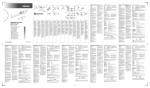
1
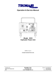
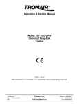
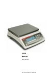
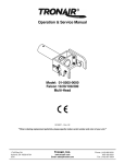
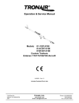
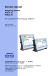
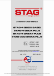
Operation & Service Manual
Model: 5B20
Hydraulic Power Unit
07/2011 - Rev. 06
Includes Illustrated Parts Lists
1740 Eber Rd
Holland, OH 43528-9794
USA
Tronair, Inc.
www.tronair.com
Email: [email protected]
Phone: (419) 866-6301
800-426-6301
Fax: (419) 867-0634
Model: 5B20
Hydraulic Power Unit
TABLE OF CONTENTS
PAGE
1.0
2.0
3.0
4.0
5.0
6.0
7.0
General Description .................................................................................................................................... 4
Technical Specifications .............................................................................................................................. 4
2.1 Hydraulic........................................................................................................................................... 4
2.2 Electrical ........................................................................................................................................... 4
2.3 Mechanical ....................................................................................................................................... 4
Preparation For Use .................................................................................................................................... 5
3.1 Servicing Reservoir ........................................................................................................................... 5
3.2 Connecting Electrical Leads .............................................................................................................. 5
Operation .................................................................................................................................................... 5
4.1 General Comments ........................................................................................................................... 5
4.2 Preliminary Adjustments And Operations .......................................................................................... 6
4.3 Sample Valve.................................................................................................................................... 6
4.4 Bleeding Air From System ................................................................................................................. 6
4.5 Abbreviated Operating Instructions.................................................................................................... 7
4.6 Options ............................................................................................................................................. 7
Maintenance ............................................................................................................................................... 8
5.1 General Maintenance ........................................................................................................................ 8
5.2 Filter Maintenance ............................................................................................................................ 8
5.3 Lubrication ........................................................................................................................................ 8
5.4 Storage ............................................................................................................................................. 8
Troubleshooting .......................................................................................................................................... 9
6.1 No Flow Or Pressure......................................................................................................................... 9
6.2 Fluctuating Pressure Or Flow ............................................................................................................ 9
6.3 Unit Overheats .................................................................................................................................. 9
Parts List Index ........................................................................................................................................... 9
APPENDIX I
APPENDIX II
APPENDIX III
APPENDIX IV
Instrument Certification Notice
Lincoln Motor Manual
Oilgear Type PVWG Pump Manuals
MSDS Hydraulic Fluid
07/2011 - Rev. 06
Model: 5B20
Hydraulic Power Unit
REVISION
01
DATE
01/05/2004
02
03
04
02/2004
02/2004
05/2004
05
06
08/2008
07/2011
TEXT AFFECTED
pg 3
Electrical Components - Drawing changed,
and parts list expanded to include numbers for
50 & 60 Hz Applications
pg 2
Replaced Electrical Schematic
Major revision
pg 13 Modified part numbers for 60 HZ & 50 HZ applications
pg 12 Modified part number for item 5
Modified Pump/Motor Assembly and Appendix III
Modified Electrical Components Parts List
07/2011 - Rev. 06
Model: 5B20
Hydraulic Power Unit
Front Panel Controls
07/2011 - Rev. 06
-1-
Model: 5B20
Hydraulic Power Unit
Electrical Schematic
07/2011 - Rev. 06
-2-
Model: 5B20
Hydraulic Power Unit
Hydraulic Schematic
07/2011 - Rev. 06
-3-
Model: 5B20
Hydraulic Power Unit
This product can not be modified without the written approval of Tronair, Inc. Any modifications done without
written approval voids all warranties and releases Tronair, Inc., it suppliers, distributors, employees, or financial
institutions from any liability from consequences that may occur. Only Tronair OEM replacement parts shall be
used.
1.0
GENERAL DESCRIPTION
The Tronair Hydraulic Power Unit (HPU) provides a source of clean, pressurized hydraulic fluid for
performing required aircraft maintenance. Some important features are:
• Pressure compensated pump with integral pressure and flow controls
• 10 gallon reservoir with selector valve
• Bypass valve
• Case drain cooler
• Manual starter with overload protection
• Non bypass filter with 2 micron filter element
2.0
TECHNICAL SPECIFICATIONS
2.1 HYDRAULIC
Fluid:
MIL-PRF-83282D
Pressure Range:
250 − 3,000 psi
Flow Range:
0 − 6 gpm
Filtration:
2 Micron Absolute
Reservoir Capacity: 13 Gallons
2.2
ELECTRICAL
Power Requirements:
60 Hz
15.0 amps @ 208 VAC
13.6 amps @ 230 VAC
8.2 amps @ 380 VAC
6.8 amps @ 460 VAC
5.4 amps @ 575 VAC
2.3
3 Phase
50 Hz
13.6 amps @ 200, 220 VAC
6.8 amps @ 380, 415, 440 VAC
MECHANICAL
Dimensions: 45 inches Long
33 inches Wide
44 inches High
Weight:
525 lbs
07/2011 - Rev. 06
-4-
Model: 5B20
Hydraulic Power Unit
3.0
PREPARATION FOR USE
The HPU is shipped completely assembled and only the following steps are required to make the unit
operational.
3.1
SERVICING RESERVOIR
Remove the sheet metal top cover and fill the reservoir with the correct fluid until fluid level is slightly
above the minimum oil level mark. Since a case drain cooler is located in the HPU reservoir, it is
important that this fluid level be maintained in order to prevent excessive heat buildup.
3.2
CONNECTING ELECTRICAL LEADS
Install plug onto the electrical cord and check for proper motor rotation by “bumping” the on-off switch.
Correct motor rotation is indicated by an arrow on pump motor adapter. If rotation is not correct,
change any two of the three input leads at the plug or inside the electrical component box.
NOTE:
Balanced three phase voltage must be available to prevent overheating and damage to the
motor.
Voltage unbalanced between phases occurs when the voltages differ from one another.
Some reasons for imbalance are:
1. Unequal loading of each phase.
2. Poor connections in the supply.
3. Single phase condition caused by blown fuses or bad connections.
If these conditions occur in the incoming power system, a protective device, such as a
voltage monitor, should be installed on the machine to prevent motor damage.
4.0
OPERATION
Due to the complexity, differences, and ongoing changes in aircraft hydraulic systems, no attempt has been
made to relate to any specific aircraft operation. It is suggested that this manual and the HPU be studied
thoroughly in order to obtain optimum benefit of the various features. By combining an understanding of the
HPU and the aircraft hydraulic system, many services not mentioned in this manual may be performed.
Refer to the hydraulic schematic, front panel controls, and internal components pages for clarification while
reading this manual.
4.1
GENERAL COMMENTS
Most questions or problems concerning hydraulic power units are usually caused by improper training
or understanding of hydraulics. The following comments are given to aid in obtaining maximum
benefits from the hydraulic power unit.
A. Training
Be sure all personnel that will use the machine read the operating manual and receive training.
We encourage customers to call Tronair to discuss any operating or testing requirements.
B. Use of the HPU on Citation III
The model 7012 HPU has some unique features required for use on the Citation III aircraft. These
include:
1. The aircraft return fluid passes through a panel mounted sight gauge prior to the HPU
reservoir. The sight gauge allows a visual indication of fluid condition and entrapped air.
2. Since it is not possible to use the aircraft reservoir, there is no reservoir selector valve.
4.0 Operation continued on following page.
07/2011 - Rev. 06
-5-
Model: 5B20
Hydraulic Power Unit
4.0
OPERATION (continued)
4.2 PRELIMINARY ADJUSTMENTS AND OPERATIONS
The following are basic to the operation of the HPU and should be thoroughly understood.
A. Flow Control Adjustment
1. Open bypass valve.
2. Start HPU.
3. Adjust flow control on pump for maximum desired flow and read flow (Gallons per minute)
directly form flowmeter scale. Be sure the control shaft lock nut is loose during adjustment.
Tighten after adjustment to maintain setting.
B. Pressure Control Adjustment
1. Open bypass valve.
2. Start HPU.
3. Close bypass valve.
4 Adjust pressure control for desired pressure. Be sure the control shaft lock nut is loose during
adjustment. Tighten after adjustment to maintain setting.
C. Bypass Valve Operation
The bypass valve is used for unloading the pump flow in conjunction with the flowmeter.
CAUTION!
Excessive heat, which could damage machine components, will be generated if the bypass
valve is partially opened or is used for regulating flow or pressure.
• Use the flow and pressure controls for regulation.
• Use the bypass valve for unloading the system.
1. Start Up Operation: The bypass valve should be opened prior to starting the HPU in order
to allow the motor to start under a no load condition.
2. Shut Down Operation: Prior to shutdown, the bypass valve may be opened to bleed off any
residual system pressure.
NOTE:
Once the flow and pressure controls have been adjusted, it is not necessary to change
these settings after each operation unless desired.
4.3
SAMPLE VALVE
A sample valve is provided on the rear of the unit to obtain a fluid sample for analysis or inspection. In
order to obtain a representative fluid sample, it is suggested that American National Standard number
B93.19-1972 be followed.
4.4
BLEEDING AIR FROM SYSTEM
Rapid fluctuations of the pressure gauge and flowmeter are indications of cavitation or entrapped air
in the hydraulic lines and/or components. Air may enter the system when:
•
•
•
Operating the unit with insufficient oil in the reservoir.
Changing a component on the aircraft.
Changing the hose connections and/or couplings.
•
•
•
•
•
•
•
•
To Easily Purge the Unit of Air:
1. Fill reservoir to recommended level.
2. Open bypass valve.
3. Start unit and adjust flow control to maximum position.
4. Run unit for 5 minutes and shut off.
5. If additional bleeding is required, proceed with the following steps.
a) Connect the pressure and return hoses together. (Kits containing the necessary fitting(s)
are available from Tronair)
b) If the unit is equipped with pressure and return ball valves, open the ball valves prior to
starting the unit.
07/2011 - Rev. 06
-6-
Model: 5B20
Hydraulic Power Unit
4.4
BLEEDING AIR FROM SYSTEM (continued)
Warning!
Failure to open the return ball valves will cause hose or valve rupture. Property damage and
personal injury can result.
c) Open the bypass valve on the instrument panel
d) Start unit and adjust flow control to maximum position.
e) Close the bypass valve and allow the unit to run for five (5) minutes.
Under some conditions where a large amount of air has entered the system, the pump may not be
able to draw an initial prime and will not pump. If this occurs, it may be necessary to fill the pump inlet
line with fluid.
4.5
ABBREVIATED OPERATING INSTRUCTIONS
These instructions may be used for fast reference after a thorough understanding of the HPU
operation has been achieved.
A. Prior to Starting
1. Open the bypass valve.
B. Initial Adjustments
1. Set flow control. (See Section 4.2.A)
2. Set pressure control. (See Section 4.2.B)
C. Operation
1. Start HPU.
2. Close bypass valve.
3. Perform aircraft tests.
D. Shut Off
1. Open bypass valve.
2. Push stop button.
4.6
OPTIONS
The following options are available on some models of hydraulic power units. Refer to the appropriate
option description for operation information.
A. Pyrometer (Option K)
The pyrometer indicates fluid temperature in the return system. It is normal for this temperature to
increase when the aircraft is not demanding any flow and the HPU is holding pressure.
CAUTION!
If this temperature rises to 150o F:
1. Operate from HPU reservoir or,
2. Open the bypass valve or,
3. Cycle the landing gear a few times or,
4. Shut off the HPU.
B. Dual System Operation (Option C)
The dual system option allows control of fluid flow to aircraft with two hydraulic systems. The
systems consist of two sets of hoses and valves located in the pressure and return systems. The
valves are mounted on the rear of the hydraulic power unit and are of the 90 degree ball type.
The valves are open when the operating handle is in line with the valve.
Although both systems may be operated simultaneously, usually only one system is required at
any one time. If both valve sets are open simultaneously, the pump output will be divided
between the two systems. Also, cross flow between the reservoirs may occur if a reservoir level
or pressure differential exists. Select valve positions prior to starting machine.
4.6 Optionscontinued on following page.
07/2011 - Rev. 06
-7-
Model: 5B20
Hydraulic Power Unit
4.6
OPTIONS (continued)
To Operate the Dual System:
1. Before starting machine, open pressure and return valves of the same system.
WARNING!
Ensure pressure and return hoses of the same system are paired and used together.
2. After completing tests on one system, shut the machine Off before selecting the second
system.
WARNING!
Never open or close dual system valves without shutting off the hydraulic power unit. Damage
to the aircraft system or reservoir may result if either return line valve is closed while the
machine is running.
3. If equipped with the Dual System Crossover Check Option, separate pressure gauges are
located after each system pressure shut off valve. This allows bleed down pressures to be
read when the pressure valves are closed. Follow aircraft manufacturer's instructions.
C. Hourmeter (Options E or F)
The hourmeter records operating hours of the HPU. The main use of the hourmeter is to schedule
filter changes.
D. Hand Service Pump (Option M)
This pump is used primarily for filling aircraft reservoirs after testing, bleeding brakes, etc.
5.0
MAINTENANCE
5.1 GENERAL MAINTENANCE
•
•
•
The Hydraulic Power Unit should be maintained in a safe and clean condition at all times.
Locate and correct the source of any and all leaks.
Inspect hoses and electrical cord periodically for damage and wear. Replace as required.
5.2
FILTER MAINTENANCE
The main pressure filter has a replaceable element that is not cleanable. It is recommended that
this filter be changed after every 25 hours of operation, annually, or whatever a reduced
maximum flow is noticed. Refer to the parts list for the correct filter element number.
5.3
LUBRICATION
The swivel casters are equipped with grease fittings which should be lubricated annually.
5.4
STORAGE
In the event that the HPU will not be used for 12 months or longer, the reservoir may be drained. The
unit should then be appropriately covered in order to maintain cleanliness.
07/2011 - Rev. 06
-8-
Model: 5B20
Hydraulic Power Unit
6.0
TROUBLESHOOTING
6.1 NO FLOW OR PRESSURE
•
•
•
•
•
6.2
FLUCTUATING PRESSURE OR FLOW
•
6.3
Flow control set too low:........................................ Increase flow setting.
Motor running in wrong direction: .......................... See Section 3.0, "Preparation for Use".
Insufficient oil in reservoir: ..................................... See Section 3.0, "Preparation for Use".
Air in hydraulic lines: ............................................. See Section 4.4, "Bleeding Air From System".
Faulty pump: ......................................................... Repair or replace pump.
Air in hydraulic lines: ............................................. See Section 4.4, "Bleeding Air From System".
UNIT OVERHEATS
•
•
•
NOTE:
Low fluid level in reservoir: .................................... See Section 3.0, "Preparation for Use".
Running unit for long time periods
Cycle landing gear or other components
without operating aircraft: ...................................... periodically or allow unit to cool components.
Bypass valve partially open: .................................. See Section 4.2.C, "Bypass Valve Operation".
Running time under deadhead condition can be increased substantially by selecting the
"Hydraulic Power Unit" position; reservoir selector valve.
When a pressure compensated pump is required to hold pressure without any flow
delivery (dead headed condition), it is normal for the pump case drain flow and
temperature to increase. By selecting the "Hydraulic Power Unit" position of the selector
valve, all of the oil in the reservoir is utilized for cooling.
7.0
PARTS LIST INDEX
When ordering Replacement Parts/Kits, please specify Model & Serial Number of your product.
Reference the following for ordering information of Replacement Parts and Kits.
Contents
Page
Bypass Valve ........................................................................................................................................... 15
Check Valve ............................................................................................................................................. 16
Control Module ......................................................................................................................................... 15
Electrical Components.............................................................................................................................. 11
External Components ............................................................................................................................... 10
HC-2161 Hand Pump Assembly ........................................................................................................ 18 − 19
Internal Hydraulic Hoses .......................................................................................................................... 10
Hand Pump (Option M)............................................................................................................................. 17
Pressure Filter .......................................................................................................................................... 14
Pressure Relief Valve ............................................................................................................................... 16
Pump/Motor Assembly ............................................................................................................................. 13
Reservoir Assembly ................................................................................................................................. 12
07/2011 - Rev. 06
-9-
Model: 5B20
Hydraulic Power Unit
External Components
ITEM
PART NUMBER
DESCRIPTION
QTY
1 ........................ U-1013 .................................................. Caster, Rigid .................................................... 2
2 ........................ H-1207 .................................................. Latch ............................................................... 1
3 ........................ HC-2267 ............................................... Pyrometer (Option K) ....................................... 1
4 ........................ HC-1399 ............................................... Gauge, Pressure.............................................. 1
5 ........................ EC-1058................................................ Switch, On/Off ................................................. 1
5 ........................ EC-1073................................................ Lamp, Replacement ......................................... 1
6 ........................ EC-1060................................................ Hourmeter (Option E or F) ............................... 1
7 ........................ H-1584 .................................................. Handle ............................................................. 1
8 ........................ HC-2150 ............................................... Flowmeter........................................................ 1
........................ HC-2150-A1 (Calibrated) ....................... Flowmeter........................................................ 1
9 ........................ U-1014 .................................................. Caster, Swivel.................................................. 2
10 ........................ H-1175 .................................................. Lock, Floor ....................................................... 1
11 ........................ TF-1039-01*180 .................................... Hose, Return ................................................... 1
12 ........................ TF-1037-01*180 .................................... Hose, Pressure ................................................ 1
13 ........................ Z-1296-01 ............................................. Hanger, Hose .................................................. 2
14 ........................ HC-1506 ............................................... Indicator, Sight Flow ........................................ 1
Internal Hydraulic Hoses
LOCATION
PART NUMBER
Case Drain Cooler to Bypass Cooler .......................................... TF-1037-05*32.0
Control Block to Bypass Cooler .................................................. TF-1037-01*28.0
Pump to Case Drain Cooler ....................................................... TF-1037-08*22.5
Pump to Flow Meter ................................................................... TF-1037-07*30.0
Control Block to Pressure Gauge ............................................... TF-1037-03*16.0
Control Block to Pressure Filter .................................................. TF-1037-04*22.0
Cooler to Flow Indicator ............................................................. TF-1039-05*17.3
07/2011 - Rev. 06
- 10 -
Model: 5B20
Hydraulic Power Unit
Electrical Components
**When ordering replacement parts/kits, please specify model, serial number and color of your unit.**
1
.
Set Item 01 to "Manual" and set "A2" to its corresponding full load amps.
ITEM
PART NUMBER
DESCRIPTION
QTY
1 ....................... EC-1834 ................................................. Relay, IEC Overload ...................................... 1
2 ....................... EC-1067 ................................................. Enclosure, Electrical ...................................... 1
3 ....................... See Table ............................................... Contactor, IEC Motor ..................................... 1
4 ....................... See Table ............................................... Transformer ................................................... 1
5 ....................... EC-1071 ................................................. Holder, Fuse .................................................. 1
6 ....................... EC-1094 ................................................. Fuse ............................................................... 1
208
230
380
60 HZ Applications
460
575
3
EC-1838
EC-1838
EC-1838
EC-1836
EC-1837
4
EC-1804-04
EC-1074
EC-1804-04
EC-1074
EC-1804-04
ITEM
ITEM
50 HZ Applications
415
200
220
380
3
EC-1838
EC-1838
EC-1836
EC-1836
EC-1836
4
EC-1804-04
EC-1074
EC-1804-04
EC-1804-04
EC-1074
07/2011 - Rev. 06
- 11 -
440
Description
Contactor, IEC
Motor
Transformer
Qty.
Description
Contactor, IEC
Motor
Transformer
Qty.
1
1
1
1
Model: 5B20
Hydraulic Power Unit
Reservoir Assembly
ITEM
PART NUMBER
DESCRIPTION
QTY
1 ........................ HC-1164 ............................................... Reservoir ......................................................... 1
2 ........................ HC-1106 ............................................... Filler, Breather ................................................. 1
3 ........................ HC-1382-08 .......................................... Gauge, Sight.................................................... 1
4 ........................ H-1735-02 ............................................. Washer, Nylon ................................................. 1
5 ........................ H-1733-01 ............................................. Gasket, Cover.................................................. 1
6 ........................ HC-1029 ............................................... Diffuser ............................................................ 1
7 ........................ HC-1107 ............................................... Strainer ............................................................ 1
07/2011 - Rev. 06
- 12 -
Model: 5B20
Hydraulic Power Unit
Pump/Motor Assembly
ITEM
PART NUMBER
DESCRIPTION
QTY
1 ........................ HC-1393-11 .......................................... Mount, Pump/Motor ......................................... 1
2 ........................ H-2227 .................................................. Spider .............................................................. 1
3 ........................ H-2224-03 ............................................. Coupling, Body/Motor ...................................... 1
♦ 4 ........................ K-4258 .................................................. Kit, Hydraulic Pump with Hardware .................. 1
5 ........................ H-2224-01 ............................................. Coupling, Body/Pump ...................................... 1
PUMP REPLACEMENT PARTS
Not Shown .................... TBD ...................................................... Shaft Seal ........................................................ 1
Not Shown .................... ♦♦TBD ................................................. Gasket & O-rings Kit ........................................ 1
Note:
All bolts are Grade 5.
♦
♦♦
See the Pump Manufacturer's Service Booklet for servicing and additional kits.
Kit includes HC-1543 Shaft Seal.
07/2011 - Rev. 06
- 13 -
Model: 5B20
Hydraulic Power Unit
Pressure Filter
ITEM
PART NUMBER
DESCRIPTION
QTY
1 ........................ HC-1083 ............................................... Assembly, Filter ............................................... 1
FILTER REPLACEMENT PARTS
2 ........................ K-1414 .................................................. Filter Element Kit ............................................. 1
3 ........................ ♦HC-2000-138 ...................................... O-ring, Bowl ..................................................... 1
♦
Item 3 is included with Item 2.
07/2011 - Rev. 06
- 14 -
Model: 5B20
Hydraulic Power Unit
Control Module
ITEM
PART NUMBER
DESCRIPTION
QTY
1 ........................ J-1476 ................................................... Body, Valve ..................................................... 1
2 ........................ HC-1262 ............................................... Valve, Check ................................................... 1
3 ........................ HC-1264-01 .......................................... Valve, Pressure Relief ..................................... 1
4 ........................ HC-1254 ............................................... Valve, Bypass .................................................. 1
Bypass Valve
ITEM
PART NUMBER
DESCRIPTION
QTY
1 ........................ HC-1254 ............................................... Assembly, Bypass Valve .................................. 1
2 ........................ HC-1130 ............................................... Handle, Valve .................................................. 1
3 ........................ HC-2010-910 ........................................ O-ring .............................................................. 1
4 ........................ HC-2020-014 ........................................ Ring, Backup ................................................... 1
5 ........................ HC-2000-014 ........................................ O-ring .............................................................. 1
6 ........................ HC-2000-012 ........................................ O-ring .............................................................. 1
07/2011 - Rev. 06
- 15 -
Model: 5B20
Hydraulic Power Unit
Pressure Relief Valve
ITEM
PART NUMBER
DESCRIPTION
QTY
1 ........................ HC-1264-01 .......................................... Valve, Pressure Relief ..................................... 1
2 ........................ HC-2010-910 ........................................ O-ring .............................................................. 1
3 ........................ HC-2000-014 ........................................ O-ring .............................................................. 1
4 ........................ HC-2020-010 ........................................ Ring, Backup ................................................... 1
Check Valve
ITEM
PART NUMBER
DESCRIPTION
QTY
1 ........................ HC-1262 ............................................... Valve, Check ................................................... 1
2 ........................ HC-2010-910 ........................................ O-ring .............................................................. 1
3 ........................ HC-2000-014 ........................................ O-ring .............................................................. 1
4 ........................ HC-2020-010 ........................................ Ring, Backup ................................................... 1
07/2011 - Rev. 06
- 16 -
Model: 5B20
Hydraulic Power Unit
Option M − Reservoir Fill Hand Pump
ITEM
PART NUMBER
DESCRIPTION
QTY
1 ........................ TF-1043-01*180 .................................... Hose ................................................................ 1
2 ........................ HC-1481 ............................................... Assembly, Filter ............................................... 1
3 ........................ K-3098 .................................................. Kit, Replacement Filter Element ....................... 1
4 ........................ TF-1043-01*27.0 ................................... Hose ................................................................ 1
♦ 5 ........................ HC-2161 ............................................... Assembly, 500 psi, Hand Pump ....................... 1
6 ........................ TF-1043-01*09.9 ................................... Hose ................................................................ 1
7 ........................ Z-4302-01 ............................................. Weldment, Filter Bracket .................................. 1
8 ........................ H-1009-01 ............................................. Handle, Pump .................................................. 1
♦ See Pages 18 & 19 for additional Information.
07/2011 - Rev. 06
- 17 -
Model: 5B20
Hydraulic Power Unit
HC-2161 (Mineral Base Fluids) Hand Pump
07/2011 - Rev. 06
- 18 -
Model: 5B20
Hydraulic Power Unit
HC-2161 (Mineral Base Fluids) Hand Pump
ITEM
FLUID
PART NUMBER
DESCRIPTION
QTY
3 ........... N/A .................................. 531-000 ................................. Clevis Pin Assembly ........................... 1
4 ........... N/A .................................. 568-120 ................................. Tie Rods ............................................ 4
5 ........... N/A .................................. 582-125 ................................. Retaining Flange ................................ 1
6 ........... N/A .................................. 504-120 ................................. Tube .................................................. 1
7 ........... N/A .................................. 507-121 ................................. Piston ................................................. 1
10 ........... N/A .................................. 503-120 ................................. Valve Block ........................................ 1
11 ........... N/A .................................. Reference Only ...................... Available only in Assembly ................. 1
13 ........... N/A .................................. CXD-020023-001 ................... Body .................................................. 1
14 ........... N/A .................................. 530-000T ............................... Retainer ............................................. 1
12 ........... Mineral Base.................... 5M2-B01-0500T ..................... Screw Release ................................... 1
21 ........... N/A .................................. 540-000 ................................. Plug ................................................... 1
22 ........... N/A .................................. 508-000 ................................. Pivot................................................... 1
Mineral Base
SRK-PSB-120
Kit, O-ring; consists of:
8 ........... Mineral Base.................... .............................................. O-ring, BUNA ..................................... 1
9 ........... Mineral Base.................... .............................................. O-ring, BUNA ..................................... 2
15 ........... Mineral Base.................... .............................................. O-ring, BUNA ..................................... 1
19 ........... Mineral Base.................... .............................................. O-ring, BUNA ..................................... 1
16 ........... N/A ..................................
17 ........... N/A ..................................
18 ........... N/A ..................................
20 ........... N/A ..................................
SRK-PHR-120
Kit, Check Ball/Spring; consists of:
.............................................. Intake Check Ball ............................... 1
.............................................. Outlet Check Spring ........................... 1
.............................................. Outlet Check Ball ............................... 1
.............................................. Intake Check Spring ........................... 1
SRK-PL-000T
Kit, Bracket; consists of:
23 ........... N/A .................................. .............................................. Linkage Pin Assembly ........................ 2
24 ........... N/A .................................. .............................................. Strap .................................................. 2
25 ........... N/A .................................. .............................................. Bracket Handle................................... 1
511-240T
Kit, Handle; consists of:
Not Shown ....... N/A .................................. .............................................. Handle Grip ........................................ 1
Not Shown ....... N/A .................................. .............................................. Handle ............................................... 1
07/2011 - Rev. 06
- 19 -
APPENDIX I
Instrument
Certification
Notice
Instrument Certification Notice
The gauge Certificates of Calibration supplied for the gauge(s) on this unit contain the
calibration data for the actual instrument calibrated, along with the calibration date of the
STANDARD used to perform the calibration check.
The due date for re-calibration of the instrument should be based upon the date the instrument
was placed in service in your facility. Re-calibration should be done on a periodic basis as
dictated by the end user's quality system or other overriding requirements.
Note that Tronair, Inc. does not supply certificates of calibration on flow meters or pyrometers
unless requested at the time of placed order. These instruments are considered reference
indicators only and are not critical to the test(s) being performed on the aircraft.
1740 Eber Rd
Holland, OH 43528-9794
USA
Tronair, Inc.
www.tronair.com
Email: [email protected]
Phone: (419) 866-6301
800-426-6301
Fax: (419) 867-0634
APPENDIX II
Lincoln
Motor
Manual
APPENDIX III
Oilgear
Type PVWJ
Pump Manuals
APPENDIX IV
MSDS
Hydraulic
Fluid