1
Bulletin 947015A
SERVICE INSTRUCTIONS
OILGEAR TYPE "PVWH", "PVWW" AND "PVW" OPEN LOOP
VARIABLE DISPLACEMENT PUMPS
PURPOSE OF INSTRUCTIONS
These instructions are written to simplify your work when installing, operating and maintaining these Oilgear pumps. Your acquaintance with the construction, principle of operation and characteristics of these units will help you attain satisfactory performance,
reduce down-time and increase the units life. Some units have been modified from those described in this bulletin and other changes
may be made without notice.
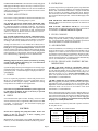
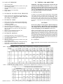
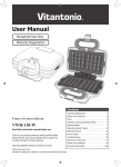
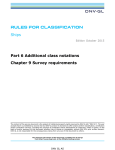
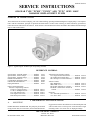
Figure 1. Typical Oilgear “PVWH" Open Loop Pump (55503R).
REFERENCE MATERIAL
Specifications, "PVWW" Pumps .................. Bulletin
Specifications, "PVW" Pumps ..................... Bulletin
Specifications, "PVWH" Pumps .................. Bulletin
Fluid Recommendations ............................... Bulletin
Contamination Evaluation Guide ................. Bulletin
Filtration Recommendations ........................ Bulletin
Piping Information ........................................ Bulletin
47013
47014
47015
90000
90004
90007
90011
Volume/Pressure Sensing Controls
"CF" Single Pressure/Load Sense ............. Bulletin 947516
"2F" Dual Pressure/Load Sense ................ Bulletin 947512
"HF" Horsepower Limit/Load Sense ........ Bulletin 947511
Pump Control Instructions
Pressure Compensating Controls
"CN & CL" Single Pressure ................... Bulletin
"C2 & C3" Multiple Pressure ................ Bulletin
"CU" Soft Start Pressure ........................ Bulletin
"CH" High-Low Pressure ...................... Bulletin
"HP" Horsepower Limiter ...................... Bulletin
947515
947518
947517
947514
947513
947816
Volume Controls
"HN" Handwheel ...................................... Bulletin
"MN & MS" Lever .................................... Bulletin
"RU & RR" Solenoid, Two Volume .......... Bulletin
"RS & RY" Solenoid Two Volume &
Neutral ................................................... Bulletin
947115
947116
947815
Electronic
"VU" Solenoid Operated Servo ................ Bulletin 947715
"VV" Servo Valve ..................................... Bulletin 947716
I. PREPARATION AND INSTALLATION
A.
MOUNTING
PUMP WITHOUT RESERVOIR. The pump may be mounted
in any position. But, for convenience, the recommended mount-
ing position is with the driveshaft axis on a horizontal plane and
with case drain "Port 1" to the top side. Secure the unit to a rigid
mounting surface. See section "B" on "Piping & Fittings".
THE OILGEAR COMPANY
Re-Issued November, 1995
2300 So. 51st. Street
Milwaukee, WI 53219
BULLETIN 947015A
PUMP WITH RESERVOIR. These units are usually fully piped
and equipped, although it may be necessary to connect to supercharge circuit when used. Mount reservoir on level foundation
with reservoir bottom at least six (6) inches above floor level to
facilitate fluid changes.
B. PIPING AND FITTINGS
See reference "Piping Information" bulletin and individual circuit diagram before connecting pump to system.
For "PVWH" and "PVW" Pumps using 150-300 SSU VISCOSITY FLUIDS, an inlet strainer is not required. Inlet should
be unrestricted and have a minimum of fittings. See reference
"Specification Bulletin" for minimum inlet "psia" requirements
at selected input rpm. If suction line is used, it should reach
within 1 to 2 times its diameter from the bottom of reservoir do not "bottom-out" tubes in reservoir.
For "PVWW" Pumps using 27-30 SSU VISCOSITY FLUIDS, pumps should have a flooded inlet and an inlet filter should
not be used. Inlet should not be restricted and have a minimum
of fittings. Inlet velocity should not exceed 3 fps. (0,9 m/s).
Arrange case drain line so case remains full of fluid (non-siphoning) at less than 25 psi (1,7 bar) and case pressure must not
be 10 psi (0,7 bar) greater than inlet pressure. Each drain line
must be separate, unrestricted, full sized and connected directly
to the reservoir below the lowest fluid level. Drain tubing should
NOT incorporate a "suction break". Provisions for opening this
line without draining (siphoning) reservoir should be made.
WARNING:
Running pump in "Neutral" position (zero delivery) for long
periods of time without supercharge (or a case bleed thru
circuit) can damage the pump.
System and pump must be protected against over-loads by separate high pressure relief valves. Install bleed valve(s) at highest
point(s) in system. Consult The Oilgear Company for other recommendations.
C. POWER
Power is required in proportion to volume and pressure used.
Motor size recommendations for specific applications can be
obtained from The Oilgear Company. Standard low starting
torque motors are suitable for most applications.
CAUTION:
Never start or stop unit under load unless system is approved
by The Oilgear Company. It may be necessary to provide
delivery bypass in some circuits.
D. DRIVE
See rotation direction plate on units’ housing. Units are available for left hand (CCW) or right hand (CW) rotation but are not
reversible. Use direct drive. Size and install coupling per
manufacturer’s instructions.
CAUTION:
E. FILTRATION
To assure long life from your hydraulic system, keep fluid clean
at all times. See reference bulletins on "Filtration Recommendations" and "Contamination Evaluation". Oilgear recommends
the use of a filter in an auxiliary (pilot) pump circuit. Replace
filter element(s) when filter condition indicator reaches "change"
area at normal fluid temperature. Drain and thoroughly clean
filter case.
FOR 150-300 SSU VISCOSITY FLUID, use of ten micron
filtration (Beta 10 of four or better) in pressure or return line is
recommended.
FOR 27-30 SSU VISCOSITY FLUID, use of ten micron
filtration (Beta 10 of fifteen or better) in pressure or return line is
recommended. Continuous filtration is required.
F. FLUID COOLING
When pump is operating continuously at rated pressure or frequently at peak load, auxiliary cooling of fluid may be necessary. Fluid temperature should not exceed limits specified in
referenced bulletin on "Fluid Recommendations".
G. AIR BREATHER
On most installations, an oil bath type air breather is mounted
on top of fluid reservoir. It is important for the breather to be of
adequate size to allow air flow in and out of reservoir as fluid
level changes. Keep breather case filled to the "fluid level" mark.
About once every six months, remove cover, wash screens in
solvent, clean and refill case to "fluid level" mark and install dry
screen. See manufactures’ recommendations.
H. FLUID, FILLING AND STARTING RECOMMENDATIONS
"PVWH" and "PVW" Pumps use 150-300 SSU VISCOSITY FLUIDS, meeting or exceeding lubricating specifications
of SAE 10W AP1 Engine Service Classifications - SC, CC or
SE (or ISOVG32 thru 68) is recommended, viscosity range 150300 SSU at 100oF (37,7oC). For fire resistant fluids, phosphate ester hydraulic fluids can be used in accordance with
manufacturer’s recommendations.
"PVWW" Pumps may use 27-30 SSU VISCOSITY FLUIDS, it is suggested you confirm your selection with your Oilgear
representative before you specify the type of hydraulic fluid.
High Water Content Fluids (HWCF) 95-5, water glycol and oil
emulsion fluids can be used in accordance with fluid
manufacturer’s recommendations.
Refer to instruction plate on unit, reservoir, machine and/or referenced "Fluid Recommendations" bulletin. Pump all fluid into
reservoir thorough a clean (see Section E for Beta ratings) filter.
Fill reservoir to, but not above, "high level" mark on sight gage
with hydraulic fluid. Remove case drain line at the pump and
fill pump case with hydraulic fluid.
Turn driveshaft a few times by hand with a spanner wrench to
be sure parts are free.
Table 1. TORQUE TO TURN SHAFT
SIZE
UNIT
Do not drive coupling onto pump driveshaft. If fit is too
tight, it may be necessary to heat coupling (see
manufacturer’s instructions).
Misalignment of pump shaft to driveshaft should not exceed
0.005" (0,13 mm) Total Indicator Readout (TIR) in any plane.
Bulletin 947015A
Page 2
04, 06, 10
11, 15, 20
25, 34, 45, 60
Approx. Torque to Turn Shaft
foot pounds
Nm
1.7 - 2.1
2.9 - 3.3
7.9 - 8.3
2,3 - 2,8
4,0 - 4,5
10,8 - 11,3
1993 THE OILGEAR COMPANY - ALL RIGHTS RESERVED
Add fluid and start again. With differential (cylinder) systems,
fluid must not be above "high level" when ram is retracted or
below "low level" when extended. Bleed air from the system by
opening air bleed petcocks at highest point in the system. Close
connections or petcocks tightly when solid stream of fluid appears.
With pump under "no load", or with pump control at "neutral"
turn drive unit on and off several times before allowing pump to
attain full speed. The system can usually be filled by running
the pump and operating the control. Watch the fluid level in the
reservoir and stop pump if the level reaches "low level" mark.
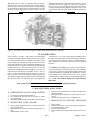
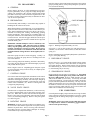
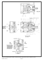
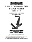
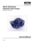
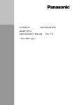
Figure 2. Cut-a-Way (cross section) of Typical "PVWH" Pump from the right side. (88050R)
II. CONSTRUCTION
Refer to Figures 2, 10 and 11. A driveshaft (1) runs through the
centerline of pump housing (5), saddle block (8) and valve plate
(22). Pump cylinder barrel (18) is splined to driveshaft. A bearing (3) supports the outboard end of the driveshaft and a bushing integral with the valve plate supports the inboard end. The
pump cylinder barrel is carried in a journal type hydrodynamic
cylinder bearing (12). The valve plate (22) has two crescent
shaped ports. Pumping piston/shoe assemblies (15) in the cylinder barrel are held against a swashblock (11) by a shoe retainer (14). The shoe retainer is held in position by a fulcrum
ball (16) which is forced outward by shoe retainer spring (17).
The spring acts against the pump cylinder barrel forcing it against
the valve plate while also forcing the piston shoe against the
swashblock (11). The semi-cylinder shaped swashblock limits
the piston stroke and can be swivelled in arc shaped saddle bearings (10A and 10B) which are pinned (9) into the saddle (8).
The swashblock is swivelled by a control (covered in referenced
material).
For "PVWH" Pumps (only), the ("pressure" side) saddle bearing is force lubricated. A small hole in the face of the swashblock
(11) provides "porting" for the hydrostatic balance fluid [of the
piston/shoe assembly (15)] through the swashblock to a rectangular shaped groove milled in one of the two arc shaped
swashblock faces, to lubricate the face of the mating saddle bearing. "PVW" and "PVWW" Pumps are not provided with
this feature.
SEE PAGES 4 and 5 "III. PRINCIPLE OF OPERATION" and "IV. SPECIFICATIONS"
V. MALFUNCTIONS AND CAUSES
A. UNRESPONSIVE OR SLUGGISH CONTROL
4.
1.
2.
5.
3.
See reference control instruction material.
Low control input (pilot) pressure for "R" and "V" volume
type controls only.
Swashblock saddle bearings (10A & 10B) worn or damaged.
B. INSUFFICIENT PUMP VOLUME
1.
2.
3.
Delivery limited by faulty control (see appropriate control
instruction material).
Obstructed suction circuit or insufficient supercharge volume.
Insufficient drive motor speed.
6.
Worn or grooved cylinder barrel (18) and/or valve plate (22)
matching surfaces.
Worn piston/shoe assemblies (15) or piston bores in cylinder (18).
Worn or damaged piston shoe or swashblock (11).
C. IRREGULAR OR UNSTEADY OPERATION
1.
2.
3.
4.
5.
Page 3
Faulty control.
Fluid level in reservoir is low or supercharge is insufficient.
Air entering hydraulic system.
Worn axial piston pump.
Faculty output circuit components (cylinder, motors, valves,
etc.).
Bulletin 947015A
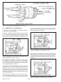
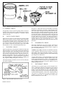
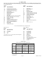
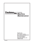
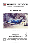
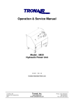
Figure 3. Type "PVWH" Pumping Mechanism (511783).
III. PRINCIPLE OF OPERATION
A ONE-WAY PUMP DRIVEN COUNTERCLOCKWISE
(LEFT HAND), IS DESCRIBED.
to Port A until it’s innermost stroke is reached. At that point, the
piston bore passes from the upper to the lower crescent again
and the operating cycle is repeated.
See Figure 3. Turning the driveshaft rotates the splined cylinder
barrel (18) which contains pumping pistons with swivel shoes
(15). A shoe retainer (14), backed up by a spring (17) loaded
fulcrum ball (16), holds piston shoes against a swashblock (11).
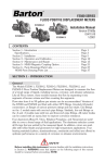
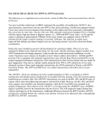
Figure 5. POSITION A/2 Plan (Top) View, Swashblock Positioned for Partial Delivery from Port A (511783).
SEE FIGURE 5. POSITION A/2. A study of the diagram will
show that the degree of swashblock angle determines the length
of the piston stroke (difference between outermost and innermost position) thereby determining the amount of delivery from
the pump.
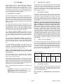
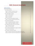
Figure 4. POSITION A Plan (Top) View, Swashblock Positioned for Full Delivery Port A. (511783)
SEE FIGURE 4. POSITION A. When the control positions
the swashblock for full delivery from Port A, the swashblock
face is at maximum angle (to the cylinder face). When cylinder
is rotated, the piston move in and out of their bores as the shoes
"ride" against the angled swashblock.
As the cylinder rotates, the individual piston bores are connected
alternately to the lower (Port B) and upper (Port A) crescent
shaped ports in the valve plate. While connected to the lower
(suction) Port B, each piston moves outward, drawing fluid from
Port B into the piston bore until it’s outermost stroke is reached.
At that point, the piston bore passes from the lower crescent port
to the upper crescent port.
While rotating across the upper crescent, each piston moves
across the angled swashblock face. Thus, each piston is forced
inward. Each piston displaces fluid thru the upper crescent port
Bulletin 947015A
Figure 6 POSITION N, Plan (Top) View, Swashblock Positioned for "Neutral" (no stroke, no delivery) (511783).
Page 4
SEE FIGURE 6. POSITION N. Neutral position results when
the control centers the swashblock. The swashblock angle is
now zero and swashblock face is now parallel to cylinder face.
Therefore, no inward or outward motion of the pump piston ex-
ist as piston shoes rotate around the swashblock face. The lack
of inward and outward motion results in no fluid being displaced
from the piston bores to the crescents in the valve plate and consequently no delivery from pump ports.
IV. SPECIFICATIONS
See referenced material, pump control material and individual application circuits for exceptions.
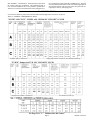
Tables 2. NOMINAL PERFORMANCE DATA
"PVWH" AND "PVW" PUMPS with 150-300 SSU VISCOSITY FLUID
1500
103,4
2000 137,9
* For higher speeds see suction curves.
64,0
47,8
Higher speeds available - consult factory Note: Minimum speed 600 rpm
"PVWW" Pumps with 27-30 SSU VISCOSITY FLUID
1200
82,7
1500
103,4
* Higher pressure available consult factory.
47.0
35,1
Note: Minimum speed 600 rpm
See Page 3 for "V". Malfunctions and Causes"
Page 5
Bulletin 947015A
D. LOSS OF PRESSURE
1.
2.
3.
4.
5.
Worn piston pump.
Worn or grooved cylinder barrel (18) and/or valve plate
(22) matching surfaces.
Worn piston/shoe assemblies (15) or piston bores in
cylinder.
Faulty output circuit components.
Faulty control.
E. EXCESSIVE OR HIGH PEAK PRESSURE
1.
Faulty output circuit components (pay particular attention to relief valves). The use of a "spike" relief valve
(fast acting) is recommended.
F. EXCESSIVE NOISE
1.
2.
3.
4.
5.
6.
7.
Pump incorrectly being stopped or started under load.
Low fluid level in reservoir or insufficient supercharge
resulting in cavitation.
Air entering hydraulic system.
Fluid too cold or viscosity to high.
Suction line problem i.e.; obstruction in line, line too
long, line diameter too small, too many bends and/or
loops in line.
Broken or worn piston/shoe assembly (15).
Pump rotating in wrong direction.
G. EXCESSIVE HEATING
1.
2.
3.
4.
5.
6.
7.
Operating pump above rated or peak pressure.
Low fluid level in reservoir or insufficient supercharge.
Air entering hydraulic system.
Worn piston pump.
Worn or grooved cylinder barrel (18) and/or valve plate
(22) matching surfaces.
Faulty output circuit components (continuous blowing
relief valve or "slip" through valves, cylinder, etc).
Insufficient cooling provision or clogged coolers.
VI. TESTING AND ADJUSTING
WARNING - Shut pump off and release pressure from the
system before disassembling components. Failure to comply
with these instructions could result in personal injury or death.
Blocking pressure line before (up-stream from) pump relief
valve or system high pressure relief valve will result in damage and could result in serious personal injury.
A. PISTON PUMP
To check for worn piston pump, measurement of the leakage
can be made from the case drain while the pump is under pressure, but pressure control (when used) is not "unloading". After
the unit is warm, either install a flow meter in the drain line or
have the flow from the drain line directed into a large container
or reservoir. The pump case must remain full of fluid during
this test.
CAUTION:
Do not run a pump on stroke against a blocked output unless it is protected by a high pressure relief valve and then
run no longer than necessary to check slip. Limit discharge
to prevent dropping reservoir fluid below "low" level.
With an accurate high pressure gage in the pressure line, start
pump, put it on stroke and stall (or block) output device to raise
system pressure to maximum (as set by system relief valve).
Read the flow meter, or time the case drain flow to fill a known
size container and calculate the flow rate in terms of cubic inches
per minute (cipm). The leakage should conform with Table 4 or
5. Additional leakage indicates wear, but does not become critical until it impairs performance.
B. CONTROL
Refer to applicable (referenced) pump control instructions material.
Table 4. "PVWH" Pump NOMINAL CASE SLIP vs. High Pressure at 1800 rpm (viscosities of 160 SSU).
1500
cipm
Table 5. "PVWW & PVW" Pump NOMINAL CASE SLIP vs. High Pressure at 1800 rpm (viscosity of 160 SSU).
1500 psi/PVW
1200 psi/PVWW
cipm
Bulletin 947015A
Page 6
Place the pump in a horizontal position and remove the rotating
group by turning shaft (1) slowly while pulling the cylinder barrel (18) from the housing.
VII. DISASSEMBLY
A. GENERAL
Refer to Figures 10 and 11. It will be advantageous to tag similar parts (particularly screws, plugs and o’rings) during disassembly to be certain they don’t become confused with similar
parts and to assure they will be returned to original location. Do
not remove (locator) roll pins unless they are deformed or otherwise in need of replacement.
B. PREPARATION
For disassembly and assembly, a crane and/or sling capable of
handling 200 lb. loads will be useful.
When disassembling or assembling unit, we recommend choosing an area where no traces of dust, sand or other abrasive particles, which could damage the unit, are in the air. We also recommend not working near welding, sand blasting, grinding
benches and the like. Place all parts on a CLEAN surface. To
clean parts which have been disassembled, it is important to use
CLEAN solvents. All tools and gages should be CLEAN prior
to working with these units and new CLEAN lint free rags used
to handle and dry parts.
WARNING: NEVER attempt to remove or install any components or assemblies while unit and system is running.
Always stop the pump, shut-off power and release pressure
from the system before servicing or testing. Be sure provisions have been made so case drain line can be disconnected
from unit without causing the line to drain (siphon) the reservoir.
Disconnect pump from drive motor and piping. Usually, it is
necessary to remove the pump from it’s mounting before the
case can be drained.
After removing pump from mounting, but before disassembly,
cap or plug all ports and clean the outside thoroughly to prevent
entry of dust into the system.
Refer to Figure 10 and 11. Depending upon what part or parts
are to be inspected, it may not be necessary to completely take
apart all assemblies.
C. CONTROL GROUP
See reference material for applicable information on the control
your unit is equipped with. Remove four hex. head cap screws
and lift the control group assembly, with control pin, straight up
from the top of the pump assembly. Control pin may or may not
remain in the swashblock (11). Remove control gasket and
o’rings from pump housing.
D. VALVE PLATE GROUP
If another unit is coupled to thru shaft units, it will be necessary
to remove coupling (half) (180 or 190) before removing valve
plate (22). Block unit on bench with driveshaft facing down.
Remove valve plate (22) by alternately removing four hex head
screws (25) and lifting straight up. Remove valve plate gasket
(21) and o’ring (28).
E. ROTATING GROUP
WARNING: Extreme care must be taken not to damage cylinder wear surface (that matches against the valve plate), bearing
diameters or piston shoes. The use of a sling, and/or assistance
from others and use of proper lifting techniques are strongly
recommended to prevent personal injury.
Figure 7. Rotating Group Disassembly (511783).
See Figure 7. Lift out shoe retainer (14) with piston/shoe assemblies (15) and remove fulcrum ball (16) and shoe retainer
spring (17).
Remove retaining ring (13) and pull hydrodynamic cylinder bearing (12) from pump housing.
F. DRIVESHAFT GROUP
Remove drive key (2) if used and driveshaft bearing retainer
ring (29). Grasp outboard end of driveshaft (1) and pull out
from pump housing. Remove shaft retainer ring (4) and front
driveshaft bearing (3). Remove seal retainer (6) and shaft seal
(7) from housing only if necessary.
G. SWASHBLOCK GROUP
Reach inside the case and remove swashblock (11). Note which
saddle bearing is in the upper (10A) position and which is in
the lower (10B) position. Remove saddle bearings (10A and
10B) from the saddle (8) if necessary. If necessary, the saddle
itself can be pulled out. On most units, the saddle is located by
pin (20) and can be pulled from the housing. On early units, the
saddle is located in the case by two dowel pins (not shown) and
the saddle is secured to the case by two nylock socket head cap
screws (not shown) which will have to be removed before the
saddle can be withdrawn from the housing.
VIII. INSPECTION
Clean all parts thoroughly. Inspect all seals, and o’rings for hardening, cracking or deterioration and replace if necessary. Check
all locating pins for damage and spring for cracking or signs of
fatigue.
WARNING: Always wear safety goggles when using solvents
or compressed air. Failure to wear safety goggles could result in serious personal injury.
Page 7
Bulletin 947015A
Figure 8. Rotating Group Inspection (511783)
A. CONTROL GROUP
See applicable reference material on pump controls. Be sure to
carefully check control pin for cracks and/or signs of fatigue.
Check fit of control pin in swashblock. It should be a slip fit
without "side-play".
B.
VALVE PLATE GROUP
Inspect the valve plate (22) surface that mates with the cylinder
barrel (18) for excessive wear or scoring. Remove minor defects by lightly stoning the surface with a hard stone that is flat
to within 0.001" (0,03mm). Be sure to stone lightly. Any excessive stoning will remove the hardened surface. If wear or damage is extensive, replace the valve plate (as part of Valve Plate
Assembly Kit No. 79L or 79R) and cylinder barrel (18).
C.
ROTATING GROUP
Inspect cylinder barrel (18) piston bores and the face that mates
with valve plate for wear or scoring. Remove minor defects by
lightly stoning the surface with a hard stone that is flat to within
0.001" (0,03 mm). Be sure to stone lightly. Any excessive stoning will remove the hardened surface. If defects can not be removed by this method, replace the cylinder barrel as part of
Rotating Group Kit No. 73. Inspect hydrodynamic cylinder bearing (12) and matching cylinder barrel surface for galling, pitting, roughness, damage and replace if necessary.
Check all piston/shoe assemblies (15) to be sure they ride properly on the swashblock.
See Figure 9. Piston shoes must pivot smoothly, but end play
should not exceed 0.006" (0,152 mm). Check end play as follows: Place square end of piston on bench and hold down firmly.
Pull on end of shoe with other hand and note end play. The shoe
must rotate and pivot on the piston ball. Inspect each shoe face
for nicks and scratches. Measure shoe thickness [the part held
between shoe retainer (14) and swashblock (11)]. All shoes must
be equal within 0.001" (0,025 mm). If a single piston/shoe assembly needs to be replaced, all piston/shoe assemblies must be
replaced. Replace as part of Piston/Shoe Kit No. 87 . When
installing a new rotating group kit, make sure pistons are free in
their bores.
D.
SWASHBLOCK GROUP
Inspect the swashblock (11) for wear or scoring. In the case of
size 60 units, inspect the swashblock wearplate (11A). If damage is extensive, replace the swashblock and/or wearplate as
part of Swashblock Kit No. 82.
"PVWH" Pumps (only), check the very small holes in the face
of the swashblock. This hole provides "porting" for the hydrostatic balance fluid (of the piston/shoe assembly) to be channelled through the swashblock to the face of the saddle bearing
(providing pressure lubrication).
Compare saddle bearing (10A and 10B) thickness in worn area
to thickness in an unworn area. Replace saddle bearings if difference is greater than 0.008 in (0,2mm). Check mating surface
of swashblock for cracks or excessive wear. Swashblock movement in saddle bearings must be smooth. Replace as part of
Saddle Bearing Kit No. 85.
E.
DRIVESHAFT GROUP
Check shaft seal (7) for deterioration or cracks. Replace if necessary. Examine the sealing area of the shaft (1) for scoring or
wear. Inspect shaft bearing (3) for roughness, galling, pitting or
binding. Check shaft and splines for wear. If driveshaft is bent,
scored or worn excessively or if bearing is bad, replace as part
of Shaft and Bearing Kit No. 74K or 74S. Inspect bushing in
valve plate (22). If replacement is necessary, the bushing is not
available as a loose item, it is included when ordering Valve
Plate Assembly Kit No. 79L or 79R.
Figure 9. Piston and Shoe Inspection (511783).
Bulletin 947015A
Page 8
B.
IX. ASSEMBLY
Refer to Figures 10 and 11. The procedure for assembling the
pump is basically the reverse order of disassembly. During assembly, install new gaskets seals and o’rings (Kit No. 77). Apply a thin film of CLEAN grease or hydraulic fluid to sealing
components to ease assembly. If a new rotating group (Kit No.
73) is used, lubricate thoroughly with CLEAN hydraulic fluid.
Apply fluid generously to all wear surfaces.
A. SWASHBLOCK GROUP
If removed, press shaft seal (7) into front of pump housing (5)
and then place housing on bench with mounting flange side
down. Place saddle block (8) into housing - center properly [a
locating hole in the saddle and a pin (20) in the housing must
match]. On early units, two dowel pins (not shown) locate the
saddle and saddle is secured to housing by two nylock socket
head cap screws.
The saddle bearings (10A and 10B) and swashblock (11) can
now be installed. Check the swashblock faces that mate with
the saddle bearings (10A and 10B). One of these faces has a
rectangular groove cut into it. The groove should be on the
control (upper) side of the swashblock for left hand driven pumps
and on the (lower) side for right hand driven pumps.
For size 04, 06, 10 and 25 "PVWH" Pumps only, the plastic
backed saddle bearing should be positioned on pin (9) to mate
with the rectangular groove milled in arc shaped swashblock
(11). Place steel backed saddle bearing on pin (9) in other location.
For size 11, 15, 20, 34, 45 and 60 "PVWH" Pumps only, both
saddle bearings are steel backed. It is recommended they be put
back in their original locations. If replacement saddle bearings
are used - it makes no difference which is placed in which location.
For all size "PVWW" and "PVW" Pumps only, both bearings
are the same. It is recommended they be put back in their original locations. If replacement saddle bearings are used - it makes
no difference which is placed in which location.
NOTE: - Install saddle bearings on size 04 thru 20 with
notched corners toward shaft and bearing. Does not apply
to 25 thru 60 size.
Place housing on its side with axis horizontal and then install
seal retainer (6). Place front driveshaft bearing (3) onto driveshaft
(1) and lock in place with shaft retaining ring (4). Lubricate
shaft seal (7) and shaft, then insert driveshaft and bearing assembly into pump housing (5) and lock in place with driveshaft
bearing retainer ring (29).
C.
Table 6. HYDRODYNAMIC BEARING LOCATION PIN
POSITION
Left Hand (CCW) Pumps = Pin at 8:00 o'clock position
between saddle protrusion and pump housing.
Right Hand (CW) Pumps = Pin at 4:00 o'clock position
between saddle protrusion and pump housing.
ROTATING GROUP
See Figure 7. Place the cylinder barrel (18), wear surface down,
on a clean cloth. Place the shoe retainer spring (17) in the center
of the barrel with the fulcrum ball (16) on top of it. Insert the
pistons/shoe assemblies (15) into the shoe retainer (14). As a
unit, fit the pistons into their bores in the cylinder barrel. DO
NOT FORCE. If aligned properly, the pistons will fit smoothly.
WARNING: Assistance from others and proper lifting technique is strongly recommended to prevent personal injury
while assembling larger sized pump rotating groups into the
pump. The rotating group can now be carefully installed over
the tail of the driveshaft (1) and into the pump housing (5). When
installing the rotating group, support the weight of the cylinder
barrel (18), as cylinder spline is passed over the tailshaft, to avoid
scratching or damage. Push cylinder forward until the cylinder
spline reaches the driveshaft spline and rotate the cylinder slightly
to engage shaft splines. Continue to slide cylinder forward until
it encounters the hydrodynamic cylinder bearing (12). Lifting
the tailshaft slightly helps cylinder barrel (18) and cylinder bearing (12) engagement. Continue pushing cylinder forward until
the piston shoes contact the swashblock. At this point, the back
of the cylinder should be located slightly outside the back of the
pump housing.
D.
VALVE PLATE GROUP
Place pump housing on bench with open end facing up. Install
new o’ring (28) and gasket (21) on housing. Make sure the tail
end of shaft engages bushing while positioning the valve plate
(22) on pins (19) and housing. Finger tighten hex head cap screw
(25) closest to o’ring (28) first and then alternately tighten other
cap screws per Table 7. On thru shaft units connected to another
pump or device, install coupling half.
Table 7. TORQUES
SIZE
UNIT
Place the swashblock into the case and be sure the swashblock
swivels in the saddle bearings. With new bearings, swivelling
may be stiff (not always smooth).
Position the hydrodynamic bearing (12) into the case so the pin
(in the bearing) will fit (per Table 6) a corresponding slot in the
housing. The bearing should fit into place with little difficulty
and be square to the axis of the pump. Tap bearing into place if
necessary, using extreme care not to damage the bearing. Insert
retaining ring (13) to hold bearing in place.
DRIVESHAFT GROUP
04, 06, 10
11, 15, 20
25, 34, 45, 60
E.
VALVE PLATE
Ft. Lbs.
N.m.
15
37
56
20,4
50,3
76,2
CONTROL
Ft. Lbs.
N.m.
8.3
8.3
16.6
11,3
11,3
22,6
CONTROL GROUP
See reference material for applicable information on the control
your unit is equipped with. See appropriate control reference
for control group mounting. See Table 8 for Torques to secure
control group to pump housing.
SEE SECTION "I. PREPARATION and INSTALLATION".
Page 9
Bulletin 947015A
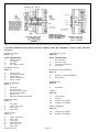
Figure 10. Parts Drawing, Basic "PVWH", "PVWW" and "PVW" Pumps without Controls. DS-SW-8A (511783)
Bulletin 947015A
Page 10
X. PARTS LISTS
Parts used in this assembly are per Oilgear Specifications. Use Oilgear parts to ensure compatibility with assembly requirements.
When ordering replacement parts, be sure to include pump type and serial number. To assure seal and packing compatibility, specify
type of hydraulic fluid used.
ITEM
NO.
1A
1B
1D
1E
2
3
4
5
6
7
8
9
10A
10B
11
11A
11B
11C
12
13
14
15
DESCRIPTION
Driveshaft w/Keyway (side port)
Driveshaft w/SAE Spline (side port)
Driveshaft w/Keyway (rear port)
Driveshaft w/SAE Spline (rear port)
Key, Driveshaft
Bearing, Front Driveshaft
Ring, Shaft Retainer
Housing, Pump
Retainer, Seal
Seal, Shaft
Block, Saddle (items 8 & 9 sold as an assembly)
Pin, Roll (items 8 & 9 sold as an assembly)
Bearing, Upper Saddle
Bearing, Lower Saddle
Swashblock
Wearplate, Swashblock (size 60 only)
Pin, Roll (size 60 "PVWH" only)
Seal, O’ring (size 60 "PVWH" only)
Bearing, Cylinder Hydrodynamic
Ring, Retainer
Retainer, Shoe
Assembly, Piston/Shoe
ITEM
NO.
DESCRIPTION
16
17
18
19
20
21
22A
22B
22C
22D
23
24
25
26
27
28
29
39
40
41
Ball, Fulcrum
Spring, Shoe Retainer
Barrel, Cylinder
Pin, Roll
Pin, Saddle Locating
Gasket, Valve Plate
Valve Plate, Side Port/rear shaft, LH
Valve Plate, Side Port/rear shaft, RH
Valve Plate, Rear Port, LH
Valve Plate, Rear Port, RH
Seal, O’ring
Plug, SAE Hollow Hex
Screw, Hex. Hd.
Nameplate, Identification
Screw, Drive
Seal, O’ring
Ring, Driveshaft Bearing Retainer
Gasket
Cover
Screw, Hex. Hd. Cap
DUAL PUMP ADAPTER AND COUPLING KITS
SIZE 04, 06 & 10
SIZE 11 THRU 60
ITEM
NO.
DESCRIPTION
ITEM
NO.
DESCRIPTION
*185
*190
*191
*192
Seal, O’ring
Lockwasher
Stud
Nut
180
181
182
183
184
185
186
187
188
189
190
191
192
Coupling, Front
Key, Coupling
Coupling, Rear
Gasket, Adapter
Adapter
Seal, O’ring
Key, Coupling
Pin, Roll
Screw, Hex. Hd. Cap
Screw, Hex. Hd. Cap (not shown)
Lockwasher (not shown)
Coupling, Spline
Pin, Roll
*Used when 04, 06 or 10 is front pump in dual arrangement
instead of bolts (188 and 189).
O’RING SIZES
ARP 568 Uniform Size Number with Durometer
ITEM
NO.
04, 06, 10
PUMP SIZE
11, 15, 20
11C
25, 34, 45, 60
"PVWH" 60 Only
006 - 70
23
902 - 90
902 - 90
28
010 - 90
010 - 90
902 - 90
*010 - 90
012 - 90
185
**
**
**
* Used on early units.
** Consult factory.
Page 11
Bulletin 947015A
Figure 11. Parts drawing Showing Driveshaft w/SAE Spline Shaft (Side Ports) DS-SW-8A. (511783)
IT IS RECOMMENDED THAT SPARE OR REPLACEMENT PARTS BE ORDERED AS PART OF THE FOLLOWING KITS.
HOUSING & PINS
KIT No. 72
SCREWS, KEY & TAG
Kit No. 80
ITEM
5
7
19
20
ITEM
2
25
26
27
DESCRIPTION
Housing, Pump
Seal, Shaft
Pin, Roll
Pin, Saddle Locating
ROTATING GROUP
Kit No. 73
14
15
16
17
18
Retainer, Shoe
Assembly, Piston/Shoe
Ball, Fulcrum
Spring, Shoe Retainer
Barrel, Cylinder
SHAFT & BEARING
Kit No. 74
1
2
3
4
6
29
Driveshaft
Key, Driveshaft
Bearing, Front Driveshaft
Ring, Front Driveshaft
Retainer, Seal
Ring, Driveshaft Bearing Retainer
DESCRIPTION
Key, Driveshaft
Screw, Hex. Hd.
Nameplate, Identification
Screw, Drive
ROTATING GROUP BEARING
Kit No. 81
12
13
Bearing, Cylinder Hydrodynamic
Ring, Retainer
SWASHBLOCK
Kit No. 82
11
Swashblock
SADDLE
Kit No. 84
GASKET & SEAL
Kit No. 77
8
9
10A
10B
7
21
23
28
SADDLE BEARING
Kit No. 85
Seal, Shaft
Gasket, Valve Plate
Seal, O’ring
Seal, O’ring
VALVE PLATE
Kit No. 79
21
22
23
24
25
28
10A
10B
Gasket, Valve Plate
Valve, Plate
Seal, O’ring
Plug, Hollow Hex
Screw, Hex. Hd.
Seal, O’ring
Bulletin 947015A
Page 12
Block, Saddle
Pin, Roll
Bearing, Upper Saddle
Bearing, Lower Saddle
Bearing, Upper Saddle
Bearing, Lower Saddle
Fold out for Parts Drawing and Parts List (page 11 and 12).
NOTES:
Page 13
Bulletin 947015A
SPARE PARTS AVAILABILITY:
XI. AFTER SALES SERVICES
Oilgear builds products that last. However, it is the nature of
this type of machinery to require proper maintenance regardless
of the care that goes into its manufacture. Oilgear has several
service programs to help you.
"STAY-ON-STREAM" SERVICE:
Prepare for future needs by stocking Oilgear original factory
parts. Having the correct parts and necessary skills "in-plant"
enables you to minimize down-time. Oilgear has developed parts
kits to cover likely future needs. Oilgear field service technicians also stand ready to assist your maintenance people in
trouble-shooting and repairing equipment.
OILGEAR EXCHANGE SERVICE
By signing up for Oilgear’s "Stay-On-Stream" program you can
prepare for problems before they happen. Certain field tests
such as fluid testing, slip testing and electronic profile recording
comparisons can be performed by our field service people or
your own trained personnel. These tests can indicate problems
before they become "down-time" difficulties.
SERVICE SCHOOLS:
Oilgear holds schools to train your maintenance personnel. A
"general" hydraulic or electronic school is conducted in our Milwaukee plant on a regular basis. "Custom" schools, specifically
addressing your particular hydraulic and electrohydraulic equipment can be conducted in your plant.
Standard replacement pumps and motors are available to users
of Oilgear equipment where comparable units will be returned
in exchange. When standard replacements must be modified to
replace units which are special, shipment will depend on availability of parts, assembly and test time necessary.
To obtain this service, place an order for an exchange unit and
provide the serial number and type designation. The replacement unit will be shipped F.O.B. our factory. Milwaukee, Wisconsin. User retains the replacement and returns the worn unit
prepaid to The Oilgear Company for reconditioning and test.
When the unit is reconditioned or stocked, the user is billed the
cost of reconditioning or a flat rate exchange price if one has
been applied to that particular type of unit.
THE OILGEAR COMPANY
BULLETIN 947015A
2300 So. 51st. Street
Milwaukee, WI 53219
Litho in USA