1
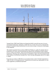
Vanmark 2920/2922 Peeler/Washer
Parts and Service Manual
Vanmark Peelers/Washers are designed and built to provide long years of service with minimal
maintenance. Operation is simple and easy to learn. However, it is important that operators be
properly trained and that they use care to prevent injury to themselves and damage to the
equipment.
This manual is provided with your Peeler/Washer as a guide for operation and as a maintenance
aid. Please read and understand this manual before attempting to install, operate, service or
repair your machine, as Vanmark does not assume any responsibility for work performed by
unauthorized personnel. Drawings, parts and instructions are identified as right or left when
facing the inlet of the machine or the direction of product flow. Parts, drawings, photographs and
text are subject to change.
Always shut-off and lock-out electrical power before performing maintenance.
If any items are unclear or difficulties are encountered, please contact Vanmark Equipment for
assistance.
2920
2/09
Vanmark, the company that developed the first commercial potato peeler, is a recognized leader
in the manufacture of food processing equipment throughout the world. Since 1954, Vanmark
has been designing and manufacturing food processing equipment to peel, scrub, wash, inspect,
fry, store and handle many types of products in the food industry.
However, we also know a great deal about processing other root crops, such as carrots, beets and
even onions. In fact, most of the carrots processed in the United States go through Vanmark
peeler / washers before heading for the consumer.
Our equipment is also used to process a variety of other vegetables and fruits, such as cabbage
and apples.
As we enter our second half-century in business, Vanmark is prepared to apply its innovative
expertise in food processing to solving challenges for a wider range of applications - for
example, golf ball manufacturing.
TABLE OF CONTENTS
SERIES 2920/2922PEELER/WASHER
1.0000 General Information
1.1000 Data Sheet
1.2000 Specifications
1.3000 Machine Description
2.0000
2.1000
2.2000
2.2100
2.2200
Installation Instructions
Receiving and Positioning
Utility Connections
Electrical
Water
3.0000
3.1000
3.2000
3.2100
3.2200
3.2300
3.2500
3.3000
3.4000
3.5000
Operating Instructions
Initial Start - Up
Adjustments
Roll Speed
Discharge Gate Adjustment
Discharge Door Removal
Autolube Adjustments
Start-up
Shut-down
General Sanitation Practice
4.0000
4.1000
4.1100
4.1200
4.1300
4.1400
4.1500
4.2000
4.3000
4.3100
4.3102
4.3105
4.3200
4.3300
4.3400
4.3500
4.3600
4.3700
4.4000
4.4100
4.4150
Maintenance
Routine Servicing
Daily
Weekly
Monthly
Quarterly
Annually
Trouble Shooting
Peeling Chamber & Rollers
Peeling Roller Removal
Splash Guard Removal
Reassembly of Peeling Rollers
Abrasive Rollers
Sinewave Abrasive Rollers
Brush Rollers
Pintle Rollers
Timing Drive Rollers
Locking Nut Assembly Instructions
Drive - Mechanical
Belt Drive
Drive Belt Replacement
2920
3/2011
TABLE OF CONTENTS
SERIES 2920/2922PEELER/WASHER
4.4200
4.4300
4.4350
4.4400
4.4500
4.5000
Replace Pulleys and Pulley Hub Bushings
Mechanical Roller Drive Case
Drive Case Removal and Installation
Drive Shaft and Roll Shaft Replacement
Roller Drive Coupling
Automatic Lube System
5.0000 Parts
5.1000 Peeling Rolls
5.2000 Natural Flow Discharge Gate
5.3000 Mechanical Drive Case
5.4000 Automatic Lube System
5.5000 Tumbling Unit Assy.
5.6000 Mid-Gate Assembly
5.7000 Mechanical Auger Discharge
5.8000 Reversing Rolls
6.0000
Spare Parts
7.0000
7.1000
7.2000
7.3000
7.3500
7.4000
7.5000
7.6000
7.6500
Charts and Schematics
Peeling Roll Configuration - Eight (8) Rolls
Electrical Schematic
Automatic Lube 120VAC
Automatic Lube 24VDC
Water Schematics
Discharge Auger & Tumbling Unit Wiring Diagram
Hz to RPM Conversion – 02920
Hz to RPM Conversion – 02922
8.0000
Component Bulletins
9.0000
Warranty
2920
3/2011
1.1000 DATA SHEET
SERIES 2920 PEELER/WASHER
Machine Number________________________ Serial Number_________________________
Purchaser:
Name _____________________________________________
Address_____________________________________________
_____________________________________________
_____________________________________________
Date Shipped: _____________________________________________
Application
_____________________________________________
Selected Options:
_____
Auto Lube System
_____
Drain Pan
_____
NEMA Motor Mount
_____
IIEC Motor Mount
_____
Pan Spray Internal Cleaning System
_____
Tumbling Unit
_____
Auger Discharge
_____
Reversing Rolls
PLEASE REFER TO THIS INFORMATION IN USING YOUR MANUAL. IN ANY
COMMUNICATIONS TO VANMARK EQUIPMENT FOR PARTS OR SERVICE; USE THIS
MODEL AND SERIAL NUMBER.
2920
2/2009
1.2000 SPECIFICATIONS
SERIES 2920/2922 PEELER/WASHER
Equipment Specifications
Approximate Weight .........................................................................(2920)1800 Lbs. /816 kg.
...........................................................................................................(2922)2200 Lbs. /998 kg.
Overall Dimensions
Length .................................................... (2920) 120.00”/305 cm - (2922)148.00”/376 cm
Width ...........................................................................................................40.00”/102 cm
Height ..........................................................................................................71.00”/180 cm
Discharge Height ........................................................................................38.00”/96.5 cm
Mechanical Rollers
Roll Speed .................................................................................................. 250 – 500 RPM
Motor .........................................................(2920)10 HP - (2922)15HP (optional voltages)
Electrical Requirement (Control) .....................Inverter, 20Hz to 90 Hz (at motor voltage)
Auger Discharge Motor
Motor ..................................................................................... 0.75 HP (Optional voltages)
Electrical Requirement (Control) .................Inverter, 20Hz to 120 Hz. (at motor voltage)
Tumbling Unit Drive Motor
Motor ..................................................................................... 1.00 HP (Optional voltages)
Electrical Requirement (Control) ................ Inverter, 30 Hz to 90 Hz. (at motor voltages)
Spray Bar
Water Flow
@ 40 PSI.................................................................................25.6 GPM (96.90 Liter/Min)
@ 60 PSI...............................................................................30.8 GPM (116.58 Liter/Min)
Water Connection................................................................................ 1.00" (Nominal) NP
Electrical Requirement (Control) .............................120 Volts, Single Phase, 60/50 Cycle
Pan Spray System
Water Flow
@ 40 PSI.......................................................................18 GPM (68.13 Liter/Min)
@ 60 PSI.......................................................................24 GPM (90.84 Liter/Min)
Water Connection...................................................................1.50” (Nominal) NP
LUBRICANTS
Grease:
Lubrication Engineers, Inc. series "H1" food machinery lubricants are recommended for
greasing tensioners. "H1" is a USDA authorized lubricant for applications which require
a non-toxic, clean lubricant.
Typical physical requirements:
NLGI Grade Code
USDA Rating
Work Penetration
Texture
Dropping Point, °F (°C)
ASTM D-942 Oxidation;
pressure drop in 100 hrs. PSIG
Color
Operating Temperature
2920/2922
2
H1
375
Tacky
470 (243)
5.0 Max.
Cream White
30 - 370° F
7/2011
1.3000 MACHINE DESCRIPTION
Vanmark Peeler/Washers are designed and built to provide long years of service with
minimal maintenance. The Series 2900 offers many options which give it the versatility
to ensure effective continuous peeling or washing to meet specific processing
requirements.
The peelers are constructed of stainless steel making them easy to clean. High quality
materials and components are used insuring long term operation with minimal
maintenance.
Peeling roller bearings in the machine are double row tapered, with both internal and
external seals to reduce the possibility of bearing failure from contamination.
Lubrication is accomplished with a manual grease bank or with an automatic lube
system.
2920
2/2009
1.3000 MACHINE DESCRIPTION
Abrasive
Nylon Brush
Rubber Pintles
Spray Nozzles
The peeling chamber consists of six (6)
rolls or eight (8) rolls with three (3) types
of surface coverings. Roller types include:
Abrasive is many grit sizes, available in
Sine - Wave, straight, agitator and lift
rolls; Nylon Brushes with varied rigidity;
and Rubber Pintles in straight, or
sinewave.
The Sine-Wave double contoured rollers
are designed to create a natural tumbling
action for consistent peel removal. The
Sine-Wave design helps prevent flat spots,
even in regular shaped fruits vegetables.
This means less waste and a clean finished
product.
A centralized water wash system is located
on the upper left side of the peeling
chamber. The water spray bar with nozzles
located along its length; provides a
constant water spray through the product
as it is being processed.
The product depth in the peeling bed is
controlled at the discharge end of the
machine with a gate or an auger,
controlling the effect of the rollers on the
product. The natural flow discharge gate is
manually adjustable. To increase or
decrease the discharge opening, the handle
is moved until the desired position of the
gate is reached. The discharge gate is a
movable hinged assembly.
2920
2/2009
2.1000 RECEIVING AND POSITIONING
2.1000 Receiving and Positioning
o Inspect machine for shipping damage and make carrier claims immediately if necessary.
o Machine is shipped on skid that may be towed on level surface by end crossmember.
Machine may also be carried on lift truck by extending forks under lowest horizontal
tubing of frame. Center of gravity is approximately one-third of overall length from inlet
end.
o NOTE: If drain pan of machine extends below lower horizontal braces, it may be
necessary to remove drain pan when using a lift truck.
o If jib crane is used to move machine, use two (2) slings under lowest horizontal tubing of
frame. Use spreaders on top of machine to reduce sling pressure against sides of machine.
o Remove four (4) bolts that go through foot pads of frame into skid and lift machine off
skid. Remove any hold-down straps or vertical bracing by cutting and discarding.
o Machine is to be located over a waste trench, or other means provided to dispose of water
and product waste. Locate machine to allow for adequate clearances to other equipment,
access to covers, removal of discharge gate or opening auger discharge, and ventilation at
drive compartment.
o Machine doors must be clear of all obstacles:
Two (2) peel chamber top
Two (2) peel chamber side doors
One (1) peel discharge gate
o Drive compartment panels to remain removable, free of plumbing and conduit mounts.
o Vanmark does not recommend drilling and taping holes in machine frame for mounting
utilities, due to sanitation issues.
o Machine must be level for proper operation. Vanmark recommends checking level, on
the bottom roller, inside the machine. Machine may have a fall of 0 – 1”/2.5cm in six (6)
feet/1.83m toward discharge end.
o Anchor machine to the floor through the holes in hold down pads in the frame, if
mounting machine on stand, or elevated framework, level machine as previously
described and then anchor it by bolting or welding to stand.
o Check that all fasteners are tight.
S2920 10/2008
2.2000 UTILITY CONNECTIONS
2.2100 Electrical
o All electrical connections shall be permanent water-tight and shall confirm to Local and
National electrical codes.
o When routing cables, conduit, and water piping; do not interfere with access to machine
covers and other moving and removable parts.
o Motor is to be connected to and controlled by inverter, for roll speed control. A 3 second
ramp-up and ramp-down delay is recommended, while recommended frequency range is
from 20 to 80 Hz. Motor and roll rotation is counter-clockwise, when viewed from the
discharge end of machine.
2.2000 Water
o Water to spray bar connection is made at 1.00” MPT located at discharge end of machine.
Vanmark recommends installation of solenoid valve connected to main drive power and
manual valve (spherical ball type) to control flow.
o Open ball valve full open to flush contaminates from new piping, check flow at nozzles,
remove and clean if necessary. Set ball valve at minimum flow setting that provides full
spray coverage of the peel chamber.
o Water to pan spray (Optional). Connection is located below discharge gate area of
machine. Connection of 1.5” MPT to have solenoid valve to operate on timer. Vanmark
recommends 1 minute on with 30 minutes off, or as needed to clean brushes.
S2920 10/08
3.1000 INITIAL START-UP
3.1001
Lubrication – At the discharge end, check grease lines to discharge bearings and
ensure they are full to the bearings with no air pockets. Check that bearings have
grease and set screws are tight.
Autolube System – Check that the grease pump reservoir is full and power is
turned on to pump.
3.1002
Discharge Gate – Check that discharge gate is set to about half way.
3.1003
Drive System – Set motor control for about 250 rpm for initial start up.
3.1004
Loose Equipment - Check that all chutes or other loose items are in their proper
place before powering up machine.
3.1005
Peeling Chamber - Check that peel chamber is clear of any loose items.
3.1006
Covers - Close and latch all covers and discharge gate
3.1007
Personnel - Check that all people are clear of machine.
3.1008
Power-Drive System - Turn on power.
3.1009
Motor Rotation - Check that shaft rotation of drive unit is clockwise when viewed
from inlet end of machine.
3.1010
Peel Roll Rotation - When viewed from the discharge end of machine, the peeling
rolls should turn counter-clockwise.
3.1011
Water - Turn on water to spray bar at machine or ahead of solenoid valve.
3.1012
Product Tests - Machine is now ready to run with product.
3.1013
Filling Bed - Allow peeler/washer chamber to fill with a deep bed of product. For
best results, product flows to machine should be kept as even as possible since
fluctuating flow will fluctuate bed depth.
3.1014
Discharge Gate - Open the discharge gate manually until the product depth levels
at a point needed to accomplish good peel removal or wash.
3.1015
End of Test - See Section 3.4000 for shut-down sequence of operation.
3.1016
Set Screws - Tighten set screws on bearings and sprockets.
3.1017
Daily Operation - Machine is now ready for production. See Section 3.3000 for
start-up sequence of operation.
2920
2/2009
3.2000 ADJUSTMENTS
Determine desired peel removal level
Set product infeed rate to match line demand
Peeler setup flow
chart
Set roll speed at 250 RPM
Set bed depth to minimum outfeed gate number
needed to get folding action
Allow operation to stabilize
Compare peel removal to desired level
Too much removed
Decrease roll speed and/or bed
depth – Maintain proper folding
action*
OK
Minimum speed and
depth reached?
No
Too little removed
Increase roll speed and/or bed
depth – Maintain proper folding
action*
Maximum speed and
depth reached?
Yes
Yes
Change rolls to less
aggressive setup
No
Change rolls to more
aggressive setup
Record Setup
* When folding action cannot be maintained
roll setup change is indicated
S2920
10/2008
3.2000 ADJUSTMENTS
3.2001 Three major factors that affect continuous peeling efficiency are:
1. Effect of roller surface on product.
2. Amount of roller surface moving past product.
3. Retention time of product in peeling chamber.
Discharge Gate position will control product load level and retention time.
Product load level will determine how much force is applied to the product on the
roll surface and will effect tumbling action.
A good tumbling action will produce a more evenly peeled product. Retention
time is how long the product is in contact with the rolls inside the machine. These
adjustments work hand in hand with roll speed.
Roll speed is a very important factor in how well your peeler/washer performs. It
is very easy to run the rolls at a higher rpm than required to achieve proper
peeling/washing. Roll over speed will cause increased peel loss and product
damage, and an inconsistent peel removal. After machine installation, take some
time to determine proper bed depth and tumbling action with as little roll rpm as
possible.
For best results, a steady inlet flow of product is necessary for consistent
machine operation.
3.2002
Adjustments are a judgment of the operator that is made by examining the product
when it reaches the inspection table. Speed of rolls and discharge gate opening
should compliment each other. Different products and product condition will
determine ultimate machine setup.
Remember - - too much peel removal creates excess product loss. Proper
adjustment is essential for efficient operation of machine.
3.2100
S2920
Roll speed on the 2920 Peeler/Washer is set with an electrical inverter. Inverter
installation and operation is the responsibility of the customer given the specific
nature of the application. Electrical requirements for this machine can be found in
section 1.2000. To find the exact Hertz output to roll RPM, a handheld
tachometer will be needed to set the roll RPM manually through the inverter. A
local certified electrician will be needed to install and program an inverter for use
by personnel.
10/2008
3.2000 ADJUSTMENTS
3.2200 DISCHARGE GATE ADJUSTMENT
To adjust discharge opening, rotate handle to
move gate to desired location.
Note: Numbers on calibration plate are for
reference in daily settings, they do not give any
specific product volume discharging from
machine.
3.2300 DISCHARGE GATE AND DOOR REMOVAL
To remove gate from door, unbolt gate
indicator from stud, then remove rotation
guides and bolts. To remove door, raise
handle and swing open door. After securing
door assembly, lightly tap hinge pins out of
the hinge flats and remove.
S2920
10/2008
3.2500 AUTOMATIC LUBE SYSTEM ADJUSTMENTS
3.25000 Automatic Lubrication Adjustments
To Fill Reservoir:
Fill the reservoir with the recommended NLGI grade
no.2 grease; always fill the reservoir thru filler fitting
(zerk). Filling or refilling of reservoir should be
performed using a lever action cartridge grease gun or
barrel pump. Use grease from a controlled suitable
dispenser. Contaminated grease will shorten the life of
the pump.
Caution: Risk of bursting if the reservoir is overfilled.
When filling the reservoir by means of pumps with a
large delivery volume, do NOT exceed the max filling
mark.
1.
2.
3.
4.
Reservoir
Pump element
Pressure relief valve
Filling nipple, Emergency
lubrication
5. Plug, piston detector
6. Filling nipple, pump
7. Printed circuit board, mounted
8. Plug, power supply
9. Plug, illuminated pushbutton
10. Return line connection (optional)
Start-up:
When switching on the power supply the
control unit of the pump is ready for service.
The machine is sent from factory with jumper, allowing functional sequence to be controlled
by the power supply. Vanmark recommends wiring the machine contact to the roll motor
inverter for remote operation. If no remote on/off switch is available, the black and the
red line must be connected externally. See section 8.0000 for Lincoln Quicklub Manual,
page 34 “Connecting Diagram”.
2920
01/2011
3.2500 AUTOMATIC LUBE SYSTEM ADJUSTMENTS
Operation:
Each time the machine contact is switched on, a functional check of the drive motor and
signal lamp takes place automatically. During the functional check the motor is switched on
for 0.1 seconds (the stirring paddle slightly rotates) and the signal lamp lights up for 2
seconds. If there is a fault, the signal lamp flashes. The proceeding of working hours and
pause times is started and stopped via the machine contact. The control unit automatically
controls the proceeding of the pause and operating times of the centralized lubrication pump.
A lubrication cycle consists of one pause time and one operating time. Once the pause time
has elapsed, the operating time starts running. The lubrication cycle is repeated permanently
after the machine has been put into operation. During the operating time the pump element
delivers the lubricant to the lubrication points via progressive metering devices.
A piston detector that has been installed
on a metering device instead of a piston
closure plug, monitors and brings the
operating time to a close after all the
pistons of this metering device have
dispensed their lubricant quantity.
A fixed monitoring time of maximum 5 minutes runs in parallel to the operating time. If
there is no switching off signal from the piston detector to the printed circuit board within 5
minutes, a fault signal will occur.
Additional lubrication cycles are possible at any time by actuating the pushbutton on the
pump, or the outside of the electrical enclosure.
Time Setting:
To set the pause or operating time, remove the
cover on the pump housing.
Important
After having set the pause time or operating
time, screw the cover on the pump housing
again.
If the housing is not closed, water may enter,
damaging components.
2920
01/2011
3.2500 AUTOMATIC LUBE SYSTEM ADJUSTMENTS
Setting of the pause time:
The pause time can be set with the
blue rotary switch to 15 stages.
The jumper above the blue rotary
switch is to set the desired time
range (4-60 minutes or 1-15 hours).
Using tweezers or pointed pliers the
setting can be carried out also with
installed printed circuit board.
Switch is set to 4-60 min. from
factory (as shown in picture.)
Vanmark
Factory Settings for (qty.) discharge bearings
Jumper position
Rotary switch position (Blue rotary switch)
(8) 40316-01-9
Min (4-60)
6 (24 min)
(16) 40316-01-9
Min (4-60)
2 (8 min)
Factory Settings for (qty.) discharge bearings
Jumper position
Rotary switch position (Blue rotary switch)
(8) 59342-01-5
Min (4-60)
F (60 min)
(16) 59342-01-5
Min (4-60)
5 (20 min)
Maintenance:
The maintenance is essentially limited to refilling the reservoir with clean lubricant in good
time. However, check regularly whether the lubricant is really dispensed to all the lubrication
points. Also check the main lines and lubricant feed lines for damage and replace them, if
necessary. Whenever work is done on the centralized lubrication system, particular attention
should be paid to absolute cleanliness. Dirt in the system will cause problems.
For cleaning the system use benzene or petroleum; do NOT use tri-, perchloroethylene or
similar solvents, or polar organic solvents such as alcohol, methylacohol, acetone or similar.
2920
01/2011
3.3000 START-UP
3.3001
Loose Equipment - Check that all chutes or other loose items are in their proper
place.
3.3002
Discharge - Manually close the discharge gate.
3.3003
Covers - Close and latch all covers.
3.3004
Power - Turn on power to roller and tumbling unit, if so equipped, drive systems.
3.3005
Water: - Turn on water to spray bar ahead of solenoid valve.
3.3006
Drive System - Engage settings to low or middle range on the indicator.
NOTE: See Section 3.2000 Adjustments
3.3007
Filling Bed - Allow peeler/washer chamber to fill with a deep bed of product.
Product fed to peeler should be controlled to flow evenly.
3.3008
Tumbling Unit - After product bed is established adjust speed range indicator so
paddle speed is slightly greater than product speed.
3.3009
Discharge Gate - Open the discharge gate manually until the product depth levels
at a point needed to accomplish good peel removal or wash.
NOTE: See Section 3.200 Adjustments.
2920
2/2009
3.4000 SHUT-DOWN
3.4001
Product Flow - Stop product flow to machine.
3.4002
Empty Bed - Slow peeling rollers to minimum speed. Allow all product to
discharge from bed.
3.4003
Water - Shut off water to spray bar manually at gate valve by machine ahead of
solenoid valve.
3.4004
Cleaning - Wash down peeling chamber. Make sure that all product residue is
removed from rolls.
IMPORTANT: During high pressure cleaning do not aim steam directly into
drive compartment or onto bearings.
3.4005
Power - Shut off electric power to drives and spray bar water solenoid.
3.4006
Water - Open water valve to spray bar.
3.4007
Covers - Close all covers.
3.4008
Clean exterior of machine - High pressure spray or a cleaning solution used with a
cloth, is recommended.
IMPORTANT: During high pressure cleaning do not aim steam directly into
drive compartment or onto bearings.
3.4009
2920
Loose Equipment - Check that all chutes and other loose items are in their proper
place.
2/2009
3.5000 GENERAL SANITATION PRACTICE
Vanmark’s equipment and parts have been designed and made of such
materials and workmanship that make them adequately cleanable when
properly maintained. It is at the equipment user’s discretion to determine
the appropriate level of sanitation required for each machine’s specific
application and location within a given facility. This should be done by the
user to maintain compliance, and consistency with each company’s own
sanitation standards. The rolls that act on product are designed for ease of
removal from the machine, and disassembly. If the cavity formed by a
hollow roll tube requires access for cleaning, the roll must be removed from
the machine and disassembled (reference section 4.3000).
02922
3/2011
4.0000 ROUTINE SERVICING
Your Vanmark Peeler/Washer is designed and constructed for efficient operation,
but it does require service and maintenance. A major breakdown can be
expensive. Therefore, it is economical to follow this routine servicing program to
assure that problems can be detected and corrected.
Service schedule is estimated based on eight (8) hours of production per day, five
(5) days per week under normal operating conditions. Schedule may require
adjustments if production time and operating conditions are different.
4.1100 Daily
• Clean peeling chamber.
• Check condition of peeling rolls.
• Check for clogged nozzles on spray bar.
• Check for line up-time (maximum number of shut-offs not to exceed three (3)
times per hour with 85 - 90% line up-time).
• Check for belt stretching and excessive wear.
4.1200 Weekly
• Check for loose or binding hardware.
• Check bearings for wear.
• Clean abrasive rolls with diluted muratic acid. Let stand approximately two (2)
hours (vary time with amount of starch and peel build up). Scrub abrasive surface
with stiff brush and rinse thoroughly. Personnel should wear personal protective
equipment as recommended by cleaning agent manufacturer or employer.
• Check all belts for stretching and excessive wear.
• Adjust drive belt if required
4.1300 Monthly
• Tighten set screws in bearings and bushings.
• Inspect roller bearing for tight fit.
4.1400 Quarterly
• Inspect inlet auger seal for wear and leakage.
4.1500 Annually
• Inspect and replace any belt with excessive wear.
• Inspect and replace each roller bearing.
2920
3/2009
4.2000 TROUBLE SHOOTING
PROBLEM
Poor Peel Removal
POSSIBLE CAUSE
SOLUTION
Tumbling (mixing) action in peeling
chamber is slow
Increase roller speed - See Section
3.2200
Replace worn rollers
Too much product in peeling chamber
Adjust discharge gate - See Section
3.2100
Maintain even infeed
Poor line up-time
Control product flow evenly - See
Section 3.2001
Abrasive rollers have starch build-up
or are worn
Clean or replace
Not enough water
Check spray bar nozzles for clogging
and adjust water flow
Brush rollers are worn
Replace
Brushes installed backwards
Reverse rolls end for end
Sequence and type of rollers is not
effective with product
Contact Vanmark for recommendation
Roller rotation is clockwise at
discharge end
Change electric motor rotation
Roller surfaces worn
Replace
Splash guards improperly aligned
Realign by lifting the masking over
roll and adjusting the splash guard
bolts
Not all rollers turning
Belt loose or broken
Repair or replace
Rollers run unevenly
Discharge gate obstructed
Remove obstruction by opening
discharge gate. Reset to desired
setting
Rollers not turning
Product or foreign item jammed in bed
Turn off power to peeler. Remove
obstruction. Restart
Product loss from
peeling chamber
2920
9/2006
4.2000 TROUBLE SHOOTING
PROBLEM
POSSIBLE CAUSE
SOLUTION
Rollers run clockwise at
discharge end
Drive motor rotation is counterclockwise
Change motor rotation
Electric drive or tumbling
unit motors do not run
Power is off
Turn on power
Wiring loose or disconnected at motor
or motor starter
Check wiring
Motor defective
Replace motor
Breaker off or tripped
Reset breaker. Turn off power to
peeler. Check peeler bed, tumbler,
drive case, belts, etc. for obstruction
that may have caused breaker to trip.
Reset breaker, turn on peeler. If
breaker continues to trip, check for
proper breaker size, based on motor
amp draw.
Roller drive motor runs,
rollers do not
Belts or pulleys worn, misaligned,
broken or loose
Replace and adjust
No water to spray bar
Manual valve closed
Open valve
Nozzles on spray bar clogged
Clean
Solenoid defective or incorrectly
wired
Replace solenoid
Drive motor is off
Turn on motor
2920
9/2006