1
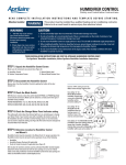
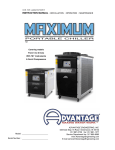
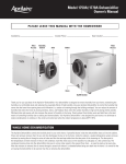
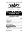
25648 RP 1780
6/8/04
11:20 AM
Page 1
SERVICE MANUAL
for
HUMIDIFIER
25648 RP 1780
6/8/04
11:20 AM
Page 3
This Service Manual is divided into two sections.
The first section is general service common to all residential models.
The second section is specific service required on individual models.
GENERAL SERVICE
PAGE
Lack of Humidity …………………………………………………………2
Excess Humidity …………………………………………………………4
Leaking Water ……………………………………………………………4
Noise ……………………………………………………………………4
General Maintenance ……………………………………………………4
INDIVIDUAL UNIT SERVICE
Models 220-224-400*-440-550-550A*-558*-560-560A*-568*-600*…6
Models 760,760A* & 700* (formerly model 768*) ……………………13
Models 445,445A* & 448* ……………………………………………16
Model 350, 360 …………………………………………………………19
Models 110 & 112………………………………………………………22
*Units featuring the Aprilaire Humidifier Control
©Research Products Corporation 2004
25648 RP 1780
6/8/04
11:20 AM
Page 4
GENERAL SERVICE
WARNING:
shock on
onModels
Model 110,
1.120
120VOLTS
VOLTSmay
maycause
causeserious
seriousinjury
injury from
from electrical
electrical shock
110, 112,
112,
350,
360,
445,
760A
and
760760,
humidifiers.
power
and768)
shut
off water
350,
360,
445,
445A,
448,
760A andDisconnect
700 (Formerly
model
humidifiers.
Disconnect power and shut off water supply before servicing or troubleshooting these
units.
supply before servicing
or troubleshooting
these units.
Rotatingororelectrical
electricalcomponents
components may
may cause
cause serious
serious injury
injury from contact.
2.2.Rotating
Keep
hands
and
face
clear
when
checking
operation.
Keep
hands
and
face
clear
when
checking
operation.
Hotwater
watertemperatures
temperaturesininexcess
excessofof125ºF
125ºFmay
maycause
causeburns.
burns.
3.3.Hot
CAUTION:
. Sudden
property damage
damage on
onModels
Model
1.
Suddenoperation
operation may
may cause
cause personal injury or property
220,
22x4,
550, 550A,
560A and
Turn600
Auto-Trac™
Control
220,
224,440,
400,550A,
440, 550,
558,560
560,humidifiers.
560A, 568 and
humidifiers.
Turn
System
of manualControl
humidistat
to “Off”humidistat
or lowest to
setting
servicing
or
the Humidifier
or manual
“Off”before
or lowest
setting
troubleshooting
these
units.
before servicing
or troubleshooting
these units.
I. LACK OF HUMIDITY (All Units)
Check Relative Humidity Level In The Home
Aprilaire Humidifier Control – Automatic Mode
• The Aprilaire Humidifier Control supplied with the Aprilaire Automatic Humidifier can be used
to measure the relative humidity (RH) in the home. To determine the relative humidity in the
home, follow these steps:
1. Determine the outdoor temperature.
2. Activate the furnace blower by setting your thermostat fan switch to the “On” position, or
by setting your thermostat to a higher temperature.
3. Turn the control dial setting to the “Off” position. Then, slowly turn the dial clockwise until
you hear the control “click ON”. Next, slowly turn the dial counterclockwise until you hear
the control “click OFF”. At this point, make note of the dial setting.
4. Locate your dial setting on Table 2. Follow the dial setting to the right until it intersects with
the current outdoor temperature. This is the relative humidity in your home under existing
conditions.
(Table 2) % Relative Humidity Guide
1
2
3
4
5
6
7
0
10
10
15
20
25
30
35
10
10
15
20
25
30
35
40
20
15
20
25
30
35
40
45
30
20
25
30
35
40
45
45
40
25
30
35
40
45
45
45
Relative Humidity (%)
Dial Setting
Outdoor Temperature (°F)
-10
10
10
10
15
20
25
30
As an example, if the outdoor
temperature is 20° F and, following step 3, the humidifier turns
OFF at “5” on the dial range,
then the relative humidity in your
home is 35%.
5. Return the thermostat and Humidifier Control to their original settings.
Aprilaire Humidifier Control – Manual Mode
• Follow steps 2 – 3, the point at which the solenoid valve opens is the humidity level in your
home.
Manual Humidistat
• The manual humidistat supplied with the Aprilaire® Humidifier is an accurate gauge that
can be used to measure the relative humidity in the home. Turn the humidistat dial to the
lowest setting. Slowly increase the setting until a light click is heard. The relative humidity in
the home will be very close to the reading at this point.
Check Windows, Fans and Fireplaces — IT IS IMPORTANT THAT THE HOUSE BE
CHECKED FOR OPEN WINDOWS, EXHAUST FANS, AND FIREPLACE DAMPERS. They provide an excellent escape route for heat, as well as humidity. Humidity is lost at an even faster
rate than heat because water vapor tends to seek its own level and you humidifier would not be
able to replace it even when running at full capacity.
Size Unit to House — The size home that can be satisfactorily humidified is determined by the
amount of outside air infiltration. The Air Conditioning, Refrigeration Institute (ARI) recommends
that home construction be classified in three general categories: loose, average, tight.
The Loose House — 2 air changes per hour.
The Average House — 1 air change per hour.
The Tight House — 1/2 air change per hour.
-2-
25648 RP 1780
6/8/04
11:20 AM
Page 5
Listed below is the square footage that each unit is designed to handle:
Chart A
Model
Square Feet Capacity * 760 /760A /768 /700
Loose House
1,050
Average House
2,100
Tight House
4,200
Model
Chart B
Square Feet Capacity *
Loose House
Average House
Tight House
(1)
(1)
(1)
Model
220
600
1,250
2,500
(1)
(1)
(1)
Model
(1)
110
112
800
1,600
3,250
1,150
2,350
4,750
Model
224
1,000
2,100
4,200
Model
440
1,000
2,100
4,200
(1)
(1)
Model
(2)
(2)
Model
350 /360 400 /560 /560A /568 /600
1,100
2,250
4,500
(1)
(1)
(1)
Model
Model
445 /445A/448 550 /550A /558
1,000
750
2,100
1,500
4,200
3,000
(1)
(1)
(1)
Models 220, 224, 400, 440, 445, 445A, 448, 550, 550A, 558, 560, 560A, 568 and 600
Total Static Pressure Drop Across Supply & Return Plenum ………………………………0.2"
(2) Calculations are based on:
a. 70ºF and 35% R.H. Indoor Air
b. 20ºF and 70% R.H. Outdoor Air
c. Internal Moisture Gain = 1 lb/hr.
d. 140ºF Service Water Temp. @ 6 GPH
e. Continuous Operation at 150 CFM
Recommended Settings — It is recommended that the temperature-humidity table noted below
be followed. Square feet capacities are based on these settings
OUTSIDE TEMPERATURE
RECOMMENDED HUMIDITY
+40ºF……………………………………………………………45%
+30ºF……………………………………………………………40%
+20ºF……………………………………………………………35%
+10ºF……………………………………………………………30%
0ºF……………………………………………………………25%
–10ºF……………………………………………………………20%
–20ºF……………………………………………………………15%
Excess humidity may result in condensation on doors, windows, inside of outer walls, and on
other exposed surfaces. If this exists, reduce the setting on the Control.
Furnace Operation — Plenum mounted humidifiers are dependent upon heat for evaporation
and normally extract this heat directly from the hot air in the supply plenum. With self-contained
units or power units applied to the return air plenum, heat required for the evaporation process
can be obtained directly from service hot water.
Lack of humidity complaints can often times be traced to oversized furnaces where the burner is
on only for a short period of time. With installations such as these, it is our recommendation that
the furnace blower be adjusted for longer operation or the blower be operated continually off the
manual setting so the humidifier can function over a longer period of time to satisfy the humidistat.
In many installations, the water supply may be switched from cold water to service hot water to
supply the necessary heat required in the evaporation process. This has also been a suggestion
when the sizing for the humidifier is marginal.
Multi-Speed Furnace Blower Motors — Furnaces with a multi-speed blower may damage the
humidifier. Premature component failure may result when interfacing Aprilaire Humidifiers with furnaces having multi-speed direct drive motors or having other than 120VAC. Use the RP Model 50
Current Sensing Relay.
Low Voltage — Disconnect electrical power. Check for low voltage in the house and at the unit
itself.
-3-
(1)
1,000
2,100
4,200
*Based on 8' ceiling height.
(1) Calculations are based on:
a. 120ºF Plenum Temperature
b. 70ºF and 35% R.H. Indoor Air
c. 20ºF and 70% R.H. Outdoor Air
d. Internal Moisture Gain = 1 lb/hr.
e. 70% Blower Operation
f. 55ºF Service Water Temperature
(1)
(1)
25648 RP 1780
6/8/04
11:20 AM
Page 6
II. EXCESS HUMIDITY
Humidity Control Check —
Check Wiring — A closed short in the low voltage control circuit leading to the humidistat may
cause the unit to run continually.
Check Relay/120 Volt Humidifier Control — A defective or sticking contact on the relay or a
defective 120 Volt humidifier control (Models 110, 112, 330, 350, 360, 445, 448, 760, 768 or 700)
may cause the unit to run continually.
Electrical Components — Failure of any electrical component in the humidifier may cause the
humidifier to run continually, if stuck in the operating position. Examination with a neon light tester
or an appropriate testing instrument will help locate which electrical component is malfunctioning.
III. LEAKING WATER (All Units Except Models 400, 445, 445A & 448)
Water Backing Up Drain Line — If the drain line does not have a continuous slope to the drain, it
is possible for it to air lock and for water to back up in the drain line. A drain safety overflow has
been molded into the lower housing of all the black plastic Aprilaire units. This safety overflow is
designed to eliminate water inside of the furnace plenum if there is a malfunction. Removing dips
and hills from the drain line and flushing it with water under pressure will eliminate the problem.
Replace drain line every year or as necessary.
Water Panel Evaporator & Scale Control Insert — A clogged Water Panel evaporator could
cause the scale control insert to fill with residue and block the drain opening, causing leaking.
Clean scale control insert and install a new Water Panel® evaporator.
Solenoid Valve — Be sure that the water flow through the valve is in the correct direction. Note an
arrow designating water flow direction on the valve bodies. Should a piece of dirt lodge between
the valve plunger and seat on the solenoid and prevent it from fully closing, the solenoid will leak.
After shutting off the water at the saddle valve, disconnect electrical power, remove the solenoid
and backwash with water under light pressure or blow out. This is quite effective unless the valve
seat has been permanently damaged, in which case, it will be necessary to replace the entire solenoid valve.
Water Pressure — Water pressure above 125 psi can cause leakage. Check pressure and use a
pressure reducer if necessary.
IV. NOISE
Solenoid Valve — There will be a "click" each time the valve opens and closes. A light gauge
plenum will amplify this noise. If the unit is not snug against the plenum, the noise is increased. If
water hammer is a problem, a length of high pressure hose installed before the valve, acts as a
cushion to reduce the noise. Check local codes before using plastic hose.
V. GENERAL MAINTENANCE
Water Panel® Evaporation Check — When the openings become clogged and restrict the airflow through the panel, it should be replaced. The life of the Water Panel evaporator will vary with
the hardness of the water, the amount of use, and the application. It is recommended that the
Water Panel be changed at least once every year (twice a year for Model 400). Replace with only
genuine RP Water Panels for continued peak efficiency and overall performance. The Water Panel
evaporator will be most efficient when installed with the colored spot at the top, if present. Make
sure the entire Water Panel is enclosed in the scale control insert.
Evaporation Check — The evaporative capacity of the Aprilaire humidifiers (excluding the models
400, 445 & 448) can be checked by determining the time it takes to fill a quart jar from the water
supply and the drain. The following formula can be used to determine the evaporation of the unit
on an hourly basis.
lb
hr
7509
seconds to
fill quart jar
The constant 7509 is obtained by multiplying the seconds per hour
(3600) times the weight of one quart of water (2.086 lbs.) Subtract the
result of the supply water check from the result of the drain water
check. The answer is the pounds of water evaporated per hour. To
convert pounds of water to gallons of water, divide by 8.343.
-4-
25648 RP 1780
6/8/04
11:20 AM
Page 7
EXAMPLE: The supply water line fills the quart jar in 2 min. 30 sec. or 150 sec. 7,509
divided by 150 = 50.1 lbs./hr. The quart jar was filled with water from the drain in 2 min.
50 sec. or 170 sec. 7,509 divided by 170 = 44.2 lb./hr. The difference between 50.1 lb./hr.
and 44.2 lb./hr. is 5.9 lb./hr. This calculates out to 0.7 gals. per hour.
1 qt.
150 sec.
2.086 lbs.
qt.
3600 sec.
hr.
=
7509
150
=
50.1 lbs./hr.
1 qt.
170 sec.
2.086 lbs.
qt.
3600 sec.
hr.
=
7509
170
=
44.2 lbs./hr.
50.1 lbs./hr.
–44.2 lbs./hr.
5.9 lbs./hr.
Prior to making an evaporation check on an Aprilaire furnace mounted humidifier, set the thermostat and humidistat so that the furnace and humidifier will run without cycling for at least
5 minutes. Allow the humidifier to operate for a minimum of 2 minutes before checking the
time to fill the quart jar at the supply and drain.
The design feed rate is 3 gph for the Models 110, 220, 550, 550A, 558, 560, 560A, 568 and 600.
This feed rate will fill a quart jar in 5 minutes. The design feed rate for the Models 112, 224, 330,
350, 360, 440, 760, 760A, 768 and 700 is 6 gph. This feed rate will fill a quart jar in 2-1/2 minutes.
The Aprilaire furnace mounted humidifiers must have an average air temperature of 120ºF to
evaporate rated capacity.
The water temperature of the Model 330, 350 & 360 must be 140ºF when checking evaporation rate.
EVAPORATIVE CAPACITY
Model 760, 760A, 768 & 700
Model 110
Model 112
Model 350 & 360
0.75 gals. water/hr
at 120ºF plenum
temperature
0.55 gals. water/hr
at 120ºF plenum
temperature
0.85 gals. water/hr
at 120ºF plenum
temperature
0.5 gals. water/hr
at 140ºF
service hot water
MODELS 220, 224, 440, 445, 448, 550, 558, 560, 568, & 600
EVAPORATIVE CAPACITY
at 120ºF Plenum Temperature
Total Static Pressure Drop Across Supply & Return Plenum . . . . . . . . . . . . . . . . .0.2”
Models 550,550A & 558 ……………………………………………………………0.50 gph
Models 400,560,560A, 568 & 600 ………………………………………………0.70 gph
Models 445,445A & 448 ……………………………………………………………0.75 gph
Model 220……………………………………………………………………………0.40 gph
Models 224, 440 ……………………………………………………………………0.70 gph
Level Unit — The unit or distribution tray must be level so that the water will be evenly distributed over the entire width of the Water Panel evaporator. If the full width of the Water
Panel evaporator is not wetted, the capacity will be reduced.
Water Feed System (All Units Except Models 445, 445A, & 448) — The water supply starts
from a saddle valve attached to a water pipe. The valve should be completely open. Water
flows to the unit through a 1/4" copper tube to a solenoid valve equipped with an in-line water
strainer. The valve electrically opens and closes to control the supply of water, and the
strainer filters particles from the water. Filtered water then goes through the orifice which
meters the water through the 1/4" tube to the distribution tray. From the distribution tray,
water flows by gravity into the Water Panel evaporator where part of the water is evaporated.
The overflow water flushes the majority of the minerals left after evaporation off the Water
Panel evaporator, through the 1/2" drain spud at the bottom of the unit through the drain line
to the floor drain. Note: With the Model 400, water that is not evaporated initially is contained
and then wicked up by the water panel to be evaporated at a later time.
To clean orifice, gently insert a fine needle through the small opening. As an alternative, use a
drill to clean out the opening: use a #77 drill (0.018” dia.) for Models 110, 220, 400, 550, 550A,
558, 560, 560A, 568 & 600; use a #73 drill (0.024” dia.) for Models 112, 224, 330, 350, 360,
440, 760, 760A, 768 & 700. If the opening cannot be cleaned out or is enlarged, replace with
new orifice (white for the 110, 220; red for the 112, 224, 330; blue for the 350, 360, 440, 760,
760A, 768, 700; yellow for the 400,550, 550A, 558, 560, 560A, 568, 600). Models 445, 445A &
448 have no orifice.
-5-
25648 RP 1780
6/8/04
11:20 AM
Page 8
INDIVIDUAL UNIT SERVICE—MODELS 220-224-400-440-550-550A-558-560-560A-568-600
MODELS 220-224-400-440-550-550A-558-560-560A-568-600
CAUTION:
1. Sudden operation may cause personal injury or property damage. Turn
the Automatic Humidifier Control or manual humidistat to "Off" or
lowest setting before servicing or troubleshooting these units.
I. LACK OF HUMIDITY
● Check The Home — See Pages 2 and 3.
● Check Furnace Operation — See Page 3.
● Check The Humidity Control — See Page 4.
● General Maintenance — See Pages 4 and 5.
1. AIR FLOW — Be sure the damper in the duct between the two plenums is open. Air
flow is based on a 0.2 total static pressure difference between the supply and return
plenums. The static pressure can be determined with a U-Tube Manometer calibrated in
inches of water. Adjust the damper to obtain proper air flow at pressures greater than 0.2
inches of water.
2. ELECTRICAL COMPONENTS — The transformer must be isolated from multispeed
motors with an RP Model 50 Current Sensing Relay. All components should be tested in
place making sure all electrical connections are secure and there are no breaks in the
service. If the solenoid valve isn’t working with the humidistat circuit closed (see diagram) and the furnace blower is running, disconnect electrical power and insert a transformer that is known to function and check. If the solenoid valve functions, replace the
transformer. If the solenoid valve does not function, replace the valve.
Note: With the Model 400, both floats must be in the down position for electrical connection.
Aprilaire Humidifier Control
Manual Humidistat
NORTH, EAST OR
WEST SIDE OF HOME
OUTDOOR
TEMPERATURE
SENSOR
TRANSFORMER
(10 VA MINIMUM)
24 VAC
*
OUTDOOR
TEMPERATURE
SENSOR & LEADS
ABOVE EXPECTED
SNOW LINE
NOTE
IMPORTANT
USE 120 VAC
POWER SOURCE
OTHER THAN FURNACE
MOTOR CIRCUIT
HOWEVER THE
TRANSFORMER
CAN BE POWERED
OFF THE HOT
120V LINE BEFORE IT
ENTERS THE
FURNACE.
LEADS
TO APRILAIRE
TERMINALS
FURNACE
BLOWER
CURRENT SENSING
RELAY
COMMON
LEAD
FURNACE
BLOWER MOTOR
HUMIDISTAT
SOME FURNACES
ARE EQUIPPED
WITH ACCESSORY
TERMINALS THAT
CAN BE USED FOR
THE HUMIDIFIER.
THE RP MODEL 50
RELAY MAY NOT BE
NECESSARY IN THIS
CASE. CONSULT
THE FURNACE
MANFACTURER'S
RECOMMENDATIONS
FOR WIRING.
MODEL
50
Note: for installation in manual mode,
replace outdoor temperature sensor
with plastic resistor case and attach
manual face plate. See form #DP10005402
for complete wiring instructions, included
with each humidifier.
*
DO NOT WIRE
SOLENOID LEADS
TO EXTERNAL
24 VAC SOURCE
120 V
24 V
TRANSFORMER
II. EXCESS HUMIDITY — See Page 4.
-6-
SOLENOID
VALVE
25648 RP 1780
6/8/04
11:20 AM
Page 9
III. LEAKING WATER — See Page 4.
The Models 220 and 224 are provided with a cover over the distribution tray. These covers
are quite effective in minimizing water bubbling out of the feed tray up to approximately
0.4 in. static pressure. A damper should be included in the bypass between the supply and
return plenum to relieve the pressure that can be created by zone dampers completely
closed with the furnace blower still operating. We might also suggest that zone dampers
be slightly cracked to relieve the pressure and therefore reduce the static pressure in the
plenum.
IV. NOISE — See Page 4.
V. Model 400 troubleshooting Procedure
The two floats in the chambers at the base of the scale control insert activate switches in
the water level sensor assembly, which control power to the solenoid valve. The float on
the right is the primary control mechanism. When the water level in the chamber on the
right rises, the float disconnects power to the solenoid valve, shutting off the water. As the
water level drops, the float activates the switch, energizing the solenoid valve, which
opens and sends water to the distributor tray. The float in the chamber on the left controls
an over-flow protection circuit. If the primary float fails to shut off the solenoid valve, water
will flow into the chamber on the left, raising that float and disconnecting power to the
solenoid valve. If both floats fail to disconnect power to the solenoid valve or if the valve
fails in the open position, water will flow into the safety overflow line.
● Check both floats, the chambers, and the float cover. Make sure the float cover is
properly snapped into place and that both floats move freely up and down.
● Check that the solenoid valve closes when de-energized.
● Check the electrical continuity of the water level sensor circuit. With both floats
down, the circuit should be closed. With either float up, the circuit should be open.
VI. GENERAL MAINTENANCE — See Pages 4 and 5.
-7-
25648 RP 1780
6/8/04
11:20 AM
Page 10
MODELS 220-224
EXPLODED RP APRILAIRE PLENUM HUMIDIFIER
(MODELS 220 & 224)
Instructions for Ordering Parts
Specify:
MODEL NO. — PART NAME — PART NO.
-8-
6/8/04
11:20 AM
Page 11
EXPLODED RP APRILAIRE PLENUM HUMIDIFIER
(MODEL 440)
MODEL 440
25648 RP 1780
Instructions for Ordering Parts
Specify:
MODEL NO. — PART NAME — PART NO.
-9-
25648 RP 1780
6/8/04
11:20 AM
Page 12
MODELS 550-550A-558-560-560A-568
EXPLODED RP APRILAIRE PLENUM HUMIDIFIER
(MODELS 550, 550A, 558 / 560, 560A, 568)
Instructions for Ordering Parts
Specify:
MODEL NO. — PART NAME — PART NO.
- 10 -
6/8/04
11:20 AM
Page 13
EXPLODED RP APRILAIRE PLENUM HUMIDIFIER
(MODEL 400)
MODEL 400
25648 RP 1780
Instructions for Ordering Parts
Specify:
MODEL NO. — PART NAME — PART NO.
- 11 -
25648 RP 1780
6/8/04
11:20 AM
Page 14
MODEL 600
EXPLODED RP APRILAIRE PLENUM HUMIDIFIER
(MODEL 600)
Instructions for Ordering Parts
Specify:
MODEL NO. — PART NAME — PART NO.
- 12 -
25648 RP 1780
6/8/04
11:20 AM
Page 15
WARNING:
1. 120 VOLTS may cause serious injury from electrical shock. Disconnect
power and shut off water supply before servicing or troubleshooting
this unit.
2. Rotating or electrical components may cause serious injury from contact. Keep hands and face clear when checking operation.
I. LACK OF HUMIDITY
● Check The Home — See Pages 2 and 3.
● Check Furnace Operation — See Page 3.
● Check The Humidity Control — See Page 4.
● General Maintenance — See Pages 4 and 5.
1. AIR FLOW/ELECTRICAL COMPONENTS — To check the fan, disconnect power and
remove cover assembly from the base assembly. The fan blade should be tight on the
shaft and 1/3 through the orifice plate toward the motorboard. If not, reposition the fan
and tighten set screw to flat on the motor shaft.
Aprilaire Humidifier Control
Manual Humidistat
APRILAIRE HUMIDIFIER CONTROL
TERMINAL STRIP
NORTH, EAST
OR WEST SIDE
OF HOME
120 VAC
FAN
OUTDOOR
TEMPERATURE
SENSOR
TRANSFORMER
(2 VA MINIMUM)
POWER
CORD
HUMIDISTAT
24 VAC
SOLENOID
VALVE
4 PIN
CONNECTOR
SOLENOID
VALVE
24 VAC
LEADS
*
24 VAC
OUTDOOR
TEMPERATURE
SENSOR & LEADS
ABOVE EXPECTED
SNOW LINE
Note: for installation in manual mode, replace
outdoor temperature sensor with plastic resistor
case and attach manual face plate. See form
#DP10005402 for complete wiring instructions,
included with each humidifier.
*
FURNACE
BLOWER
CORD & PLUG
TO 120VAC
60Hz POWER
SUPPLY
FAN
MOTOR
HUMIDISTAT
MODEL
50
LEADS
TO APRILAIRE
TERMINALS
DO NOT WIRE
SOLENOID
LEADS TO
EXTERNAL
24 VAC
SOURCE
NOTE
120 VAC
HUMIDISTAT
24 VAC
SOLENOID
VALVE
FAN
POWER
CORD
CORD & PLUG
TO 120VAC
60Hz POWER
SUPPLY
4 PIN
CONNECTOR
SOME FURNACES ARE EQUIPPED
WITH ACCESSORY TERMINALS THAT
CAN BE USED FOR THE HUMIDIFIER.
THE RP MODEL 50 RELAY MAY NOT BE
NECESSARY IN THIS CASE. CONSULT
THE FURNACE MANFACTURER'S RECOMMENDATIONS FOR WIRING.
SOLENOID
VALVE
CURRENT SENSING
RELAY
COMMON
LEAD
FURNACE
BLOWER MOTOR
IMPORTANT
USE 120 VAC POWER SOURCE
OTHER THAN FURNACE
MOTOR CIRCUIT.
FAN
MOTOR
- 13 -
MODELS 760-760A-768-700
INDIVIDUAL UNIT SERVICE—MODELS 760, 760A, 768 & 700
25648 RP 1780
6/8/04
11:20 AM
Page 16
The motor will operate if power is connected to the unit, the furnace blower is running
and the humidistat switch is closed. To check the fan motor:
APRILAIRE HUMIDIFIER CONTROL- AUTOMATIC AND MANUAL MODE
1. Replace the cover assembly and reconnect power.
2. Activate furnace blower and call for heat by turning your thermostat up to a higher
temperature.
3. Turn knob to “Test” position.
4. With furnace blower operating and furnace calling for heat, the fan motor as well as
the solenoid valve of the humidifier will operate for one minute.
5. After one minute, the humidifier and Humidifier Control will shut off.
6. Turn knob back to original setting.
MANUAL HUMIDISTAT
1. Replace the cover assembly and reconnect power.
2. Activate furnace blower by setting your thermostat fan switch to the “ON” position.
3. Turn humidistat dial to its highest setting.
4. With furnace blower operating and furnace calling for heat, the humidifier fan motor
as well as the solenoid valve of the humidifier will operate.
5. After approximately one minute, turn dial back to original setting.
6. Turn thermostat fan switch back to original setting.
If the humidifier does not operate, disconnect power and check all wiring connections
and humidistat contacts. If a Model 50 relay is being used, check the installation instructions concerning the number of wire wraps. Reconnect power and check operation. If
the unit does not operate, disconnect power.
Remove the cover assembly from the base assembly. Mark the fan blade position and
remove it from the motor shaft. Using a small screw driver, depress the plastic side tabs
on the 4 pin electrical connector and remove it from the orifice plate. Remove the 4
screws that connect the orifice plate and bridge to the cover. Place the bridge section so
that the circuit board and motor are facing up.
Remove the wires from the circuit board terminals labeled “humidistat”. Place a jumper
wire across these terminals. Reconnect the power. The fan motor leads are 120 VAC!
Use extreme caution! Check the voltage across the fan terminals and solenoid terminals. If either component is not working, replace that particular component. If voltage is
not present at either terminal, replace the circuit board.
II. EXCESS HUMIDITY — See Page 4.
III. LEAKING WATER — See Page 4.
IV. NOISE — See Page 4.
V. GENERAL MAINTENANCE — See Pages 4 and 5.
- 14 -
6/8/04
11:20 AM
Page 17
EXPLODED RP APRILAIRE PLENUM HUMIDIFIER
(MODELS 760 760A 768 & 700)
22
12
18
15
14
6
17
16
19
20
10
1A or 1B
4
5
7
11
9
10
21
8
13
Instructions for Ordering Parts
Specify:
MODEL NO. — PART NAME — PART NO.
- 15 -
3
2
MODELS 760-760A-768-700
25648 RP 1780
25648 RP 1780
6/8/04
11:20 AM
Page 18
INDIVIDUAL UNIT SERVICE—MODELS 445, 445A & 448
MODELS 445-445A-448
WARNING:
1. 120 VOLTS may cause serious injury from electrical shock. Disconnect
power and shut off water supply before servicing or troubleshooting
this unit.
2. Rotating or electrical components may cause serious injury from contact. Keep hands and face clear when checking operation.
I. LACK OF HUMIDITY
● Check The Home — See Pages 2 and 3.
● Check Furnace Operation — See Page 3.
● Check The Humidity Control — See Page 4.
● General Maintenance — See Pages 4 and 5.
1. WATER SUPPLY PROBLEMS
a. Disconnect electrical power. Remove the motor board cover. Lubricate self-aligning motor bearings at the yellow hole on top and inside the yellow mark on the side of
the motor. After lubrication, carefully remove reservoir and pump cap. Remove any
deposits present in the pump column, impeller area or pump cap. Clean out pump
cap outlet. Hold shaft at impeller and rotate slowly while working shaft up and down.
Check operation.
b. Water level in reservoir should be 1/2" from top of black reservoir liner. If necessary,
bend float arm up slightly to adjust water level.
c. Position the impeller properly in the center of the pump cap. The impeller must have
the black marking up towards the motor. (Fig. 1)
d. Open water outlet in the pump cap with 5/32" drill bit. (Fig. 1)
e. Remove feed tube. Flex to remove deposits and flush with water under pressure.
Reattach feed tube and remove any sharp bends.
f. Check operation. If motor does not operate, check for pump motor cooling fan
obstructions. Pump motor cooling fan must not be pushed too far down on shaft or it
will obstruct shaft rotation. If motor still does not operate, replace motor.
2. AIR FLOW — Be sure the damper in the duct between the two plenums is open! Air
Flow is based on a 0.2 total static pressure difference between the supply and return
plenums. The static pressure can be determined with a U-Tube Manometer calibrated
in inches of water. Adjust the damper to obtain proper air flow at pressures greater
than 0.2 inches of water.
- 16 -
25648 RP 1780
6/8/04
11:20 AM
Page 19
3. ELECTRICAL COMPONENTS — All components should be tested in place making
sure all electrical connections are secure and there are no breaks in the service. If the
pump motor isn’t working with the humidistat circuit closed (see diagram) and the furnace blower running, disconnect electrical power and connect the blue motor lead
directly to the black power cord lead and check. If the pump runs, replace the
relay/transformer or 120 volt humidifier control (after Serial No. 337,941). If the pump
doesn’t run, or water flow does not reach outlet feed nozzle, replace the pump motor.
II. EXCESS HUMIDITY — See Page 4.
III. LEAKING WATER
● Reservoir and Pump Section
The Model 445, 445A and 448 are circulating units which will require maintenance
every 30 days. Complete servicing instructions for both the water reservoir and circulating pump are located in the homeowners manual.
Aprilaire Humidifier Control
Manual Humidistat
NOTE
SOME FURNACES ARE EQUIPPED
WITH ACCESSORY TERMINALS THAT
CAN BE USED FOR THE HUMIDIFIER.
THE RP MODEL 50 RELAY MAY NOT BE
NECESSARY IN THIS CASE. CONSULT
THE FURNACE MANFACTURER'S RECOMMENDATIONS FOR WIRING.
APRILAIRE HUMIDIFIER CONTROL
TERMINAL STRIP
IMPORTANT
NORTH, EAST
OR WEST SIDE
OF HOME
OUTDOOR
TEMPERATURE
SENSOR
TRANSFORMER
(2 VA MINIMUM)
*
24 VAC
OUTDOOR
TEMPERATURE
SENSOR & LEADS
ABOVE EXPECTED
SNOW LINE
USE 120 VAC
POWER SOURCE
OTHER THAN
FURNACE
MOTOR CIRCUIT
HOWEVER THE
TRANSFORMER
CAN BE POWERED
OFF THE HOT 120V
LINE BEFORE IT
ENTERS THE
FURNACE.
Note: for installation in manual mode, replace
outdoor temperature sensor with plastic resistor
case and attach manual face plate. See form
#DP10005402 for complete wiring instructions,
included with each humidifier.
*
HUMIDISTAT
CURRENT SENSING
RELAY
COMMON
LEAD
24 VAC
LEADS
FURNACE
BLOWER MOTOR
FURNACE
BLOWER
MODEL
50
YELLOW
YELLOW
CORD & PLUG
TO 120VAC
60Hz POWER
SUPPLY
CORD & PLUG
TO 120VAC
60Hz POWER
SUPPLY
YELLOW
PUMP
MOTOR
GROUND
BLUE
GROUND
WHITE
RELAY
TRANSFORMER
WHITE
RELAY
TRANSFORMER
BLACK
BLACK
YELLOW
GREEN
BLUE
GREEN
IV. NOISE
● Pump Motor
a. Disconnect electrical power. Remove the motor board cover.
b. Check fan blade.
c. Oil with two drops SAE #20 oil in the yellow hole on top and inside the yellow
mark on the side of the motor.
V. GENERAL MAINTENANCE — See Pages 4 and 5.
- 17 -
25648 RP 1780
6/8/04
11:20 AM
Page 20
EXPLODED RP APRILAIRE PLENUM HUMIDIFIER
(MODELS 445, 445A & 448)
MODELS 445-445A-448
26
20A or 20B
Instructions for Ordering Parts
Specify:
MODEL NO. — PART NAME — PART NO.
- 18 -
25648 RP 1780
6/8/04
11:20 AM
Page 21
WARNING:
1. 120 VOLTS may cause serious injury from electrical shock. Disconnect
power and shut off water supply before servicing or troubleshooting
these units.
2. Rotating or electrical components may cause serious injury from contact. Keep hands and face clear when checking operation.
I. LACK OF HUMIDITY
● Check The Home — See Pages 2 and 3.
● Check Furnace Operation — See Page 3.
● Check The Humidity Control — See Page 4.
● General Maintenance — See Pages 4 and 5.
1. AIR FLOW — Disconnect electrical power and remove the inlet grille and Wet Pak®.
With hands and face clear, reconnect electrical power. If the fan blade is not rotating and
the motor shaft is, disconnect electrical power and secure the blade on the shaft. When
the blade is in the proper position, 1/3 of the blade extends thru the orifice towards the
outlet adapter or grille and 2/3 is thru the orifice towards the motor.
RELAY TRANSFORMER OR
120 VOLT HUMIDIFIER CONTROL
BLUE
BLACK
(2) YELLOW WIRES
TO HUMIDISTAT
FAN
WHITE
GREEN
CORD & PLUG
TO 120VAC
60Hz POWER
SUPPLY
BLACK
BLACK
BLACK
WHITE
BLACK
BLACK
GREEN
GROUND
2. ELECTRICAL COMPONENTS — All components should be tested in place before
removal, making sure all electrical connections are secure and there are no breaks in the
service. The 120 volt humidifier control replaces the relay/transformer after Serial No.
17500 (Model 350) and after Serial No. 16715 (Model 360).
II. EXCESS HUMIDITY — See Page 4.
III. LEAKING WATER — See Page 4.
IV. NOISE — See Page 4.
V. GENERAL MAINTENANCE — See Pages 4 and 5.
- 19-
MODELS 350-360
INDIVIDUAL UNIT SERVICE—MODELS 350 & 360
25648 RP 1780
6/8/04
11:20 AM
Page 22
MODEL 350
EXPLODED RP APRILAIRE PLENUM HUMIDIFIER
(MODEL 350)
Instructions for Ordering Parts
Specify:
MODEL NO. — PART NAME — PART NO.
- 20 -
6/8/04
11:20 AM
Page 23
EXPLODED RP APRILAIRE PLENUM HUMIDIFIER
(MODEL 360)
MODEL 360
25648 RP 1780
Instructions for Ordering Parts
Specify:
MODEL NO. — PART NAME — PART NO.
- 21 -
25648 RP 1780
6/8/04
11:20 AM
Page 24
INDIVIDUAL UNIT SERVICE—MODELS 110 & 112
MODELS 110-112
WARNING:
1. 120 VOLTS may cause serious injury from electrical shock. Disconnect
power and shut off water supply before servicing or troubleshooting
these units.
2. Rotating or electrical components may cause serious injury from contact. Keep hands and face clear when checking operation.
I. LACK OF HUMIDITY
● Check The Home — See Pages 2 and 3.
● Check Furnace Operation — See Page 3.
● Check The Humidity Control — See Page 4.
● General Maintenance — See Pages 4 and 5.
1. AIR FLOW — Disconnect electrical power and turn off
water supply. Remove unit from plenum and remove upper
housing. With hands and face clear, reconnect electrical
power. If the fan blade is not rotating and the motor shaft is,
disconnect electrical power and secure the blade on the
shaft. When the blade is in the proper position, 1/3 of the
blade extends thru the opening in the shroud towards the
motor and 2/3 is thru the shroud towards the Water Panel.
In some unusual situations, there may be a particular air
movement thru the plenum that makes it difficult for the fan to
draw new air into the Water Panel evaporator. In a situation like this, install 6” dividers
between the intake and discharge of the air flow as shown in the above diagram. This will
eliminate the possibility of recirculating air that is already humidified.
2. ELECTRICAL COMPONENTS — There are two electrical circuits in the Models 110- 112:
a 24 volt control circuit and a 120 volt power circuit. Failure of any electrical components in
the humidifier may result in a lack of humidity or if stuck in the operating position could
result in excess humidity. All components should be tested in place before removal making
sure all electrical connections are secure and there are no breaks in the service.
Old Style – Up to Serial # 484,805 (Model 110); 410,760 (Model 112)
a. Disconnect electrical power and check humidistat switch contacts and all wiring connections.
b. If both the motor and solenoid are not operating, the trouble may be in the relay. Disconnect
electrical power and insert a relay that is known to function and check.
c. If motor and solenoid still won’t function, disconnect power to the furnace and replace the
transformer.
d. If either the motor or solenoid valve is not operating and the other is operating, the relay transformer and humidistat can be eliminated as a source of trouble. Disconnect electrical power
and replace the motor or solenoid valve whichever is not working.
APRILAIRE HUMIDIFIER
GREEN
GROUND
WHITE
WATER
VALVE
BLACK
120 VAC
RELAY
FAN
MOTOR
BRACKET
HUMIDISTAT
24 VAC
TRANSFORMER
FURNACE
BLOWER
MOTOR
120 VAC
- 22 -
25648 RP 1780
6/8/04
11:20 AM
Page 25
New Style After Serial #484,805 (Model 110);
410,760 (Model 112) and with Date Code
a. Disconnect electrical power and check humidistat switch contacts and all wiring
connections.
b. If both the motor and solenoid are not operating, the trouble may be in the relay
transformer or the 120 volt humidifier control (after Serial #800,535–Model 110 or
534,903–Model 112). Disconnect electrical power and insert a 120 volt humidifier
control or relay transformer that is known to function and check operation.
c. If either the motor or solenoid valve is not operating and the other is operating,
the relay transformer and humidistat can be eliminated as a source of trouble.
Disconnect electrical power and replace the motor or solenoid valve whichever is
not working.
NOTE
SOME FURNACES ARE EQUIPPED WITH ACCESSORY TERMINALS THAT CAN BE USED FOR THE
HUMIDIFIER. THE RP MODEL 50 RELAY MAY NOT
BE NECESSARY IN THIS CASE. CONSULT THE
FURNACE MANFACTURER'S RECOMMENDATIONS
FOR WIRING.
HUMIDISTAT
110 & 112 APRILAIRE HUMIDIFIER
BLACK
FAN
MOTOR
WATER
SOLENOID
VALVE
CURRENT SENSING
RELAY
BRACKET
COMMON
LEAD
YELLOW
BLACK
BLACK
YELLOW
BLACK
RELAY
TRANSFORMER
BLUE
24 VAC
LEADS
FURNACE
BLOWER MOTOR
IMPORTANT
USE 120 VAC POWER SOURCE
OTHER THAN FURNACE
MOTOR CIRCUIT.
WHITE
WHITE
GREEN
CORD & PLUG TO 120VAC
60Hz POWER SUPPLY
II. EXCESS HUMIDITY — See Page 4.
III. LEAKING WATER — See Page 4.
The Models 110 and 112 are provided with a cover over the distribution tray. These covers
are quite effective in minimizing water bubbling out of the feed tray up to approximately 0.4
in. static pressure. The cover should be sealed with duct tape above this static pressure.
IV. NOISE — See Page 4.
V. GENERAL MAINTENANCE — See Pages 4 and 5.
- 23 -
25648 RP 1780
6/8/04
11:20 AM
Page 26
MODELS 110-112
EXPLODED RP APRILAIRE PLENUM HUMIDIFIER
(MODELS 110 & 112)
Instructions for Ordering Parts
Specify:
MODEL NO. — PART NAME — PART NO.
-24 -
25648 RP 1780
6/8/04
11:20 AM
Page 27
Here are five more products to help you in your quest
for... Indoor Air Quality
For the ultimate in humidity control,
the Aprilaire Humidifier Control is
available. Installed out of sight, its
exclusive microprocessor technology automatically adjusts to changing outdoor temperatures. This is your assurance of always receiving
the optimum humidity level according to outside conditions without the
need for manually adjusting your humidifier.
In addition to humidification, air
cleaning is an important part of the
total comfort indoor air quality concept. The Aprilaire High Efficiency
Air Cleaner removes up to 99% of the pollen and up to 90% of the
dust and dirt from the air circulating through your forced air system.
This high efficiency air cleaner is non-electronic, produces no
ozone, and saves money on initial and operating costs. Contact your installing contractor for
details on this fine product.
Aprilaire Electronic Thermostats combine convenience, comfort and energy
savings in an attractive, award-winning
design. Electronic thermostat adjusts
indoor temperatures automatically to fit your lifestyle. It's easy to program and is so technically advanced it constantly monitors itself to
ensure uninterrupted comfort and operation.
For year-round fresh air in
your home, ask your dealer
for details on the Aprilaire Energy Recovery Ventilator.
You can overcome the problems associated with stale,
polluted indoor air. The Energy Recovery Ventilator unit incorporates state-of-the-art technology to provide fresh air to your entire home with minimal loss of energy.
Aprilaire Zone Control System keeps every
area in your home more comfortable by providing conditioned air only to the area of the
home that requires it. By directing the conditioned air only where it’s needed, the zone control system can reduce your energy bills by up to 20%. Ask your dealer for details on the
zone control system; there’s no easier way to ensure comfortable temperatures throughout
your home.
25648 RP 1780
6/8/04
11:20 AM
Page 28
®
P.O. BOX 1467 • MADISON, WI 53701-1467
Call toll-free 1-800-334-6011 • FAX 608/257-4357
FORM NO. 1780 3.04.04
DP10006354
Printed in U.S.A.