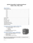
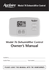
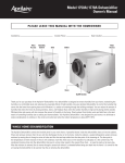
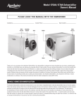
1
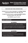
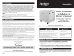
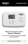
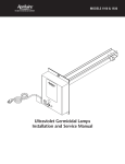
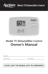
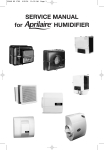
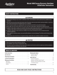
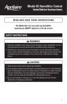
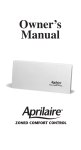
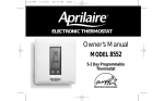
Living Space Control
Model 70 Living Space Control
Installation Manual
For use with Aprilaire® Central Dehumidifier
Models 1700, 1720, 1710, 1750, 1770, 1710A, 1750A, 1770A
WARNING
120 volts may cause serious injury from electrical shock. Disconnect electrical power to
the furnace & air conditioner before starting installation. This Living Space Control is not
a 120 volt (line voltage) device.
Improper installation may cause serious injury from electrical shock. This product must
be installed by a qualified heating & air conditioning contractor in accordance with NEC
Standards and applicable local and state codes.
SPECIFICATIONS
Low Dew Point Control Level (“MORE DRY” or 7 bars on display)
40°F
High Dew Point Control Level (“LESS DRY” or 1 bar on display)
65°F
Temperature Sensor Range
40°F to 100°F
Relative Humidity Sensor Range
30% to 100%
Temperature Storage Conditions
-30°F to 120°F
Relative Humidity Storage Conditions
0 to 100%
Supply Voltage (DC from Central Dehumidifier Control Board)
12 VDC
LIVING SPACE CONTROL INSTALLATION INSTRUCTIONS
STEP 1. CHOOSE A LOCATION TO MOUNT THE CONTROL
The Model 70 Living Space Control contains its own sensors that override the Aprilaire Central
Dehumidifier main control sensors when connected and enabled. Therefore, the control should be
located in an area (living room, master bedroom, etc.) where the homeowner wants to monitor and
control moisture levels at a convenient location.
MOUNT CONTROL…
• Approximately 5 feet off the floor (refer to local codes for compliance with the Americans
with Disabilities Act).
• On an interior wall where the humidity is representative of the home being dehumidified.
• At least 18 inches away from an outside wall.
DO NOT MOUNT CONTROL…
• Behind doors, in corners or other dead air spaces.
• In direct sunlight, near lamps or other sources of heat.
• On an outside wall or any wall exposed to an unconditioned space (i.e. garage).
• In the airflow path of a supply register or near outside doors.
• On a wall where concealed pipes or ductwork will affect the control temperature and
relative humidity accuracy.
STEP 2. DISASSEMBLE THE CONTROL
Carefully remove the front cover from
the backing plate. See Figure 1.
Figure 1 – Disassemble the Control
LL
PU
T
AR
AP
BACKING PLATE
FRONT COVER
STEP 3. MOUNT THE CONTROL ON THE WALL
There are two mounting screws and two drywall anchors provided with the control. See Figure 2.
1. Route wires through square hole in
backing plate. Level backing plate
against wall and mark two of the
mounting holes.
Figure 2 – Mount the Control
2. Drill two 3/16” diameter holes at the
marked locations and install drywall
anchors (included). Drywall anchors
should be used unless installing on
paneling or other hard surfaces.
Anchors should be flush with the wall
surface. (Note: Mounting holes on
backing plate are designed to fit on a
horizontal J-box.)
ANCHOR
BACKING PLATE
SCREW
3. Secure the backing plate to the wall using the two screws (included). Make sure all wires extend
through the square hole in the backing plate.
STEP 4. WIRE THE CONTROL
IMPORTANT! ENSURE THE POWER AT THE HVAC
EQUIPMENT AND CENTRAL DEHUMIDIFIER IS OFF.
1. Strip 2” of cable insulation.
Figure 3 – Wire the Control
2. Strip 1/4” of insulation from each wire. Do not cut into
the wire when stripping insulation, as this can lead to
eventual control failure.
3. Secure the wires to the backing plate and main control
terminal strips according to the Figure 3 wiring
diagram. Use a slotted screw driver with a 1/8”
tip (terminal screw driver).
SYSTEM SETUP
DEHUMIDIFIER MAIN CONTROL
A
B
B
+
–
+
–
MODEL 70 BACKING PLATE
A
REMOTE CONTROL
B
A
REMOTE CONTROL
SYSTEM SETUP
4. Slide excess cable back into the wire entry
wall opening and fill the hole with insulation.
Failure to seal the hole can cause drafts to
enter the control and effect humidity (moisture
level) sensing accuracy.
Figure 4 – Integrated Sensor Control Board
SYSTEM
5a. If connecting to a Central Dehumidifier
with Integrated Sensor Control Board
(Figure 4):
SETUP
OFF
ON
MODEL 70
MODEL 70
Ensure that Switch 1 in the “SYSTEM SETUP”
block on the Integrated Sensor Control Board
has been set to “MODEL 70 ON”.
90-1489
5b. If connecting to a Central Dehumidifier
with Removable Sensor Control Board
(Figure 5):
• There is no switch that is required to be
moved as the dehumidifier auto senses the
connection to a Model 70 during power up.
Figure 5 – Removable Sensor Control Board
• In coastal areas, due to high concentrations
of salt present in the air, we recommend
removing the sensor board from the
dehumidifier after the Model 70 is
installed.
REMOVABLE
SENSOR
BOARD
90-1486
STEP 5. REASSEMBLE THE CONTROL
No tools required – snap the front cover back on the backing plate, being careful to align the 6-pin
terminal block on the cover with the receptacle on the backing plate.
STEP 6. PERFORM CHECK-OUT
1. Turn the HVAC equipment back on to normal operating set points.
2. Turn the Dehumidifier main power on using the toggle switch at the rear (outlet) of the unit.
3. Press the “ON” button on the Model 70 to allow the Dehumidifier to operate.
The Model 70 Control should show a solid “ON” on the display.
4. The factory default setting is 3 bars. Adjust the
buttons to obtain a different set point level,
if desired. NOTE: After initial power-up, the dehumidifier will not run until 2– 6 minutes have
elapsed for system initialization.
RESEARCH PRODUCTS CORPORATION
1015 E. Washington Ave. • Madison, WI 53703 • Phone: 608/257-8801 • Fax: 608/257-4357 • www.aprilaire.com
10006367 8.09
B2203506D