1
TECHNICAL SERVICE MANUAL
GENERAL PURPOSE SPECIAL MOUNTED PUMPS
SERIES 75 AND 475
SIZES G-HL
SECTION TSM 320.2
PAGE
1 OF 10
ISSUE
B
INTERCHANGEABILITY
CONTENTS
Introduction
Interchangeability
Special Information
To Reassemble Model G75 &GG75
To Reassemble Model H75, HJ75 & HL75
To Reassembly Model G475 & GG475
To Reassembly Model H475, HJ475 & HL475
Safety Relief Valve Instructions
Pressure Adjustment
1
1
2
5
6
7
8
9
9
INTRODUCTION
The illustrations used in this manual are for identification
purposes only and should not be used for ordering parts.
Secure a parts list from the factory or a Viking representative.
Always give complete name of part, part number and
material, with the model number and serial number of the
pump when ordering repair parts. This model number and
serial number can be found on the nameplate attached to the
pump casing. This is important identification for ordering
parts or a replacement pump. It is positive assurance you will
receive the correct pump parts.
Your pump is composed of four major parts. Only two of
these are moving parts, the rotor and idler.
An exploded parts drawing and list of parts is included to help
you identify each part correctly. However to disassembly and
reassemble the pump you will be covered step by step. Refer
to pages 2 to 9.
These pumps are furnished with either a mechanical seal or
lip seal.
All models of the mechanical seal pumps and lip seal pumps
are dimensionally interchangeable on any NEMA "C" flange
motor. The mechanical seal is interchangeable with the lip
seal in all pump sizes.
INSTALLATION
The suction line should be air tight and at least as large as
the pump section port connections to prevent loss of prime or
capacity. It should also be equipped with a strainer and if
pumping light liquids at a high suction lift, a foot or check
valve should be used. Always avoid high spots and
obstructions in the suction line as these may cause noise,
loss of capacity or air lock. Since these pumps are the
positive displacement type, be sure there is no obstruction in
the discharge line and all valves are in operating position
before starting the pump. Be sure the adjusting screw of the
relief valve on the pump point towards the suction port.
Factory assembled pumps will have right hand port suction
and left hand port discharge unless otherwise specified. Port
location is determined by looking at mounting flange end of
pump. The relief valve on the pump is excellent insurance
against a clogged discharge line or closed valves in the
discharge line.
UNMOUNTED PUMP MODELS
WITH LIP SEAL
WITH MECHANICAL SEAL
G75
G475
GG75
GG475
H75
H475
HJ75
HJ475
HL75
HL475
MOUNTED PUMP MODELS
WITH
NORMAL GPM
WITH LIP SEAL
MECHANICAL
@ 2000
@ 1800
SEAL
RPM
RPM
G75M
G475M
5
7
GG75M
GG475M
7
10
H75M
H475M
10
15
HJ75M
HJ475M
13
20
HL75M
HL475M
20
30
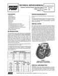
FIGURE 1
UNMOUNTED PUMP SHOWING FRONT
VIEW OF G AND GG SIZE
VIKING PUMP INC. •
A Unit of IDEX Corporation •
SPECIAL INFORMATION
MAINTENANCE
ROTATION: Viking pumps operate equally well in a
clockwise or counterclockwise rotation. Shaft rotation
determines which port is suction and which is discharge. Port
in area where pumping elements (gear teeth) come out of
mesh is suction port.
The Series 75 and 475 pumps are designed for long
trouble free life under a wide variety of application
conditions, with minimum maintenance, however the
following should be considered.
PRESSURE RELIEF VALVES:
1.
LUBRICATION – External lubrication not required for
this series of pumps. The liquid being pumped
lubricates the internal bearings in the pump.
2.
END CLEARANCE ADJUSTMENT – After long term
operation it is sometimes possible to improve the
performance of the pump, without major repair, by
adjusting the end clearance. Refer to instructions
under assembly of the pump for information regarding
this procedure.
3.
SAFETY RELIEF VALVE – If your pump is equipped
with a safety relief valve, adjustment can be made as
follows. Remove the adjusting screw cap, turn in the
adjusting screw to increase the pressure and turn-out
to decrease the pressure. If the pump is not producing
the rated capacity adjustment of the safety relief valve
may be necessary. Be sure adjusting screw cap is reinstalled before pump is started.
4.
CLEANING THE PUMP - It is good practice to keep
the pump as clean as possible. This will facilitate
inspection, adjustment and repair work.
5.
STORAGE - If the pump is to be stored or not used for
any appreciable length of time it should be drained and
a light coat of lubricating and preservative oil should
be applied to the internal parts
1. Viking pumps are positive displacement pumps and must
be provided with some sort of pressure protection. This
may be a relief valve mounted directly on the pump, an
inline pressure relief valve, a torque limiting device or a
rupture disk.
2. This series of pumps may be equipped with an integral
pressure relief valve. Standard configuration is for
clockwise rotation (suction on the right viewing the shaft
end of the pump) but it also may be ordered for counter
clockwise rotation. The valve cannot be reversed for
opposite rotation.
3. If pump rotation is reversed during operation, pressure
protection must be provided on both sides of pump.
4. Relief valve adjusting screw cap must always point
towards suction side of pump.
5. Pressure relief valves cannot be used to control pump
flow or regulate discharge pressure.
For additional information on pressure relief valves, refer to
Technical Service Manual TSM000 and Engineering Service
Bulletin ESB-31.
NOTE: Lip seal pumps, Model G75, GG75, H75, HJ75,
HL75, G75M, GG75M, H75M, HJ75M and HL75M are
equipped with an internal suckback arrangement. A small
suckback screw (self-locking) is inserted in a hole on the
discharge side of the pump. This can be seen through the
port opening and behind the rotor, (refer to figure 3). The
hole on the suction side must be left open to prevent damage
to the lip seals. Both holes are plugged in the mechanical
seal pump Model G475, GG475, H475, HJ465, HL475,
G475M, GG475M, H475M, HJ475M, and HL475M. Since
these pumps have only two moving parts and are all
performance tested at the factory, they seldom cause trouble.
If trouble does occur we always advise investigating all other
possible causes before disassembling the pump. Most
troubles are caused by air leaks and obstruction in the
suction line.
SUGGESTED REPAIR TOOLS: The following tools must
be available to properly repair Series 75 and 475 pumps.
These tools are in addition to standard mechanics’ tools
such as open end wrenches, pliers, screw drivers, etc.
Most of the items can be obtained from an industrial supply
house.
1. Soft Headed hammer
2. AlIen wrenches (some mechanical seals and set collars)
3. Mechanical seal installation sleeve
4. Brass bar
5. Arbor press
SECTION TSM 320.2
ISSUE
B
PAGE 2 OF 10
FIGURE 2
MOTOR MOUNTED PUMP SHOWING
H, HJ AND HL SIZE
JACKSCREW
HOLE
LIP SEALS (2)
MOTOR KEY
HEAD
IDLER
MOTOR SHAFT
ROTOR
CHECK END
CLEARANCE
SUCKBACK SCREW
MOUNTING CAPSCREW
MOTOR
FIGURE 3
CUTAWAY OF H, HJ AND HL 75
LIP SEAL PUMP
SECTION TSM 320.2
ISSUE
B
PAGE 3 OF 10
DISASSEMBLY
DANGER
BEFORE OPENING ANY VIKING PUMP LIQUID
CHAMBER
(PUMPING
CHAMBER,
RESERVOIR, RELIEF VALVE ADJUSTING CAP
FITTING ETC.) BE SURE:
1. THAT ANY PRESSURE IN CHAMBER
HAS BEEN COMPLETELY VENTED
THROUGH SUCTION OR DISCHARGE
LINES
OR
OTHER
APPROPRIATE
OPENINGS OR CONNECTIONS.
2. THAT THE DRIVING MEANS (MOTOR,
TURBINE, ENGINE, ETC.) HAS BEEN
“LOCKED OUT” OR MADE NONOPERATIONAL SO THAT IT CANNOT BE
STARTED WHILE WORK IS BEING DONE
ON PUMP.
3. THAT YOU KNOW WHAT LIQUID THE
PUMP HAS BEEN HANDLING AND THE
PRECAUTIONS NECESSARY TO SAFELY
HANDLE THE LIQUID. OBTAIN A
MATERIAL
SAFETY
DATA
SHEET
(MSDS) FOR THE LIQUID TO BE SURE
THESE
PRECAUTIONS
ARE
UNDERSTOOD.
FAILURE TO FOLLOW ABOVE LISTED
PRECAUTIONARY MEASURES MAY RESULT
IN SERIOUS INJURY OR DEATH.
1. REMOVE THE PUMP FROM THE MOTOR. Remove the
four capscrews and use three as jackscrews in the
threaded holes of the pump from motor shaft.
NOTE: If the pump has a valve it must be removed first to
have room for the jackscrews.
2. REMOVE PUMP HEAD.
NOTE: Mark the head and casing before disassembly to
make sure they are reassembled properly. The idler pin,
which is offset in the pump head, should be properly
positioned toward and equal distance between the port
connections to allow for proper flow of liquid through the
pump.
If it is necessary to disassemble the pump for inspection
or repair, first remove the head capscrews and remove
head by tapping the head removing lugs lightly.
3. REMOVE THE HEAD GASKETS. If a new set is not
available, the original gaskets may be reused provided
they are not damaged.
4. REMOVE THE IDLER FROM THE IDLER PIN. If idler pin
is worn, both the head, idler pin and idler bushing should
be replaced.
If the idler bushing is worn, a new bushing is needed.
If the new bushing is carbon graphite, special care must
be taken when pressing it into the idler. An arbor press
should always be used; be sure the bushing is started
straight. DO NOT STOP the pressing operation until
bushing is in its proper location. Carbon graphite is brittle;
starting and stopping the pressing operation frequently
results in a cracked bushing. If cracked in the idler, the
bushing, will quickly disintegrate.
5. REMOVE THE ROTOR FROM THE CASING. The rotor
of the two smaller pumps (G & GG sizes) can be removed
by pressing of the end of hollow drive end of the rotor. It
will be necessary on the models with mechanical seals
(G475 & GG475) to use an arbor press and an arbor of
approximately 1.375" diameter. The seal will remain in
the casing.
The rotor of the three larger size pumps (H, HJ, HL sizes)
can also be removed by pushing on the hollow drive end
of the rotor. The spring and rotary member of the
mechanical seal will come out with the rotor in these
pumps.
6. REMOVE THE MECHANICAL SEAL OR LIP SEALS.
(See figure 4) Remove the snap ring in the casing of the
two smaller pumps (G and GG sizes) and the complete
seal can be removed out of the large flanged end of the
casing.
Remove the spring and rotary member from the rotor and
the seal seat or lip seals from the pump end of the casing
of the three larger size pumps (H, HJ, HL).
REASSEMBLY
Reassembly of these pumps is explained by one of the
following sets of instructions. Follow the instructions for the
proper pump model.
Before starting to reassemble the pump, clean all parts
thoroughly and replace those, which show signs of excessive
wear or damage.
SNAP RING
CAUTION
WHEN THE HEAD IS BEING REMOVED, THE
IDLER USUALLY STAYS ON THE IDLER PIN.
AVOID TILTING THE INSIDE OF THE HEAD
DOWNWARD, AS THE IDLER MAY SLIDE OFF
THE IDLER PIN AND FALL. A FALL ON A HARD
SURFACE CAN DAMAGE THE IDLER. IF THE
IDLER SHOULD FALL, CHECK CAREFULLY
AND FILE OR STONE ALL NICKED OR ROUGH
PLACES BEFORE REASSEMBLY.
FIGURE 4
VIEW OF FLANGE END OF G AND
GG475 MECH. SEAL PUMPS
SECTION TSM 320.2
ISSUE
B
PAGE 4 OF 10
To Reassemble Model G75 or GG75
Lip Seal Pumps: (see Figure 7)
1.
INSTALL THE LIP SEALS. The lip seals should be
installed in the casing one at a time from the large
flanged end. The sealing lips must face away from each
other.
NOTE: Use an arbor press with an arbor of 2.188
diameter and press the lip seals in the casing as far as
the will go. See figures 7, 8, 9, and 10 for a cross section
of your pump models.
2.
LUBRICATE THE LIP SEALS. Fill the area between the
lips of the lip seals with grease.
3.
INSTALL THE ROTOR. Flush the rotor hub with light oil
(not grease) and insert the rotor in the casing with the
hub through the lip seals.
MOUNTING FLANGE
IDLER
HEAD
CRESCENT
ROTOR
LIP SEALS (2)
CAUTION
TURN THE ROTOR BACK AND FOURTH AS
YOU EXERT ENOUGH FORCE TO PUSH IT
THROUGH THE LIP SEAL AND TO THE
BOTTOM OF THE CASING. BE CAREFUL NOT
TO FOLD UNDER THE LIP OF THE INNER
SEAL.
FIGURE 7
SECTIONAL DRG. OF MODELS G75, GG75
LIP SEAL PUMPS
6.
4.
INSTALL THE IDLER. Put the idler with the bushings on
the idler pin.
5.
PLACE HEAD GASKETS ON THE PUMP HEAD. The
proper amount of gaskets should be used to provide
necessary end clearance within the pump so it turns
freely with no appreciable end play. Gasket table 1 gives
the normal amount of gaskets used.
THE HEAD CAN NOW BE ASSEMBLED ON THE
PUMP. Tilt the top of the head away from the pump
slightly until the crescent enters the inside diameter of
the rotor and rotate the idler until its teeth mesh with the
rotor teeth. Do not damage the head gaskets. Note
correct position of idler and crescent (See figure 7 and
Disassembly step 2). Tighten the head capscrews and
then check the end clearance.
FIGURE 5
EXPLODED VIEW SERIES 75 & 475 PUMPS (G AND GG SIZE)
ITEM
1
2
3
4
5
6
7
8
9
NAME OF PART
Key for Motor Shaft (Full Length)
Snap Ring (Used with Mech. Seal Pumps Only)
Mechanical Seal (Complete)
Lip Seal (2)
Casing
Capscrews (Pump on Motor)
Gasket For Relief Valve or Cover Plate)
Relief Valve
Capscrews (For Relief Valve or Cover Plate)
ITEM
10
11
12
13
14
15
16
17
18
NAME OF PART
Pipe Plugs-1/8"
Machine Screw (2 for Mech. Seal Pump, 1 for Lip Seal Pump)
Rotor
Idler
Idler Bushings
Gasket (for Head)
Idler Pin
Head
Capscrews (For Head)
SECTION TSM 320.2
ISSUE
B
PAGE 5 OF 10
FIGURE 6
EXPLODED VIEW SERIES 75 & 475 PUMPS (H, HJ AND HL SIZE)
ITEM
1
2
3
4
5
6
7
8
9
7.
NAME OF PART
Key for Motor Shaft (Full Length)
Capscrew (Pump to Motor)
Casing
Machine Screw (2 for Mech. Seal Pump, 1 for Lip Seal Pump)
Pipe Plugs-1/8"
Gasket (For Relief Valve or Cover Plate)
Relief Valve
Capscrews (For Relief Valve or Copper Plate)
Mechanical Seal (Complete)
CHECK PUMP END CLEARANCE. Measure clearance
between the back of the rotor and the mechanical
surface in the bottom of the casing by inserting a feeler
gauge through the port opening. This is the end
clearance; normal amount is 0.003" to 0.005". Add or
remove gaskets until the figure is reached.
NORMAL
AMOUNT
USED
(Inch)
G75 AND GG75
Lip
Seal Pumps
8.
.010" - .015"
9.
NAME OF PART
Lip Seal (2)
Rotor
Idler
Idler Bushing
Gasket (For Head)
Idler Pin
Head
Capscrews (For Head)
ASSEMBLE THE PUMP ON THE MOTOR. Install the
full length key in the keyway of the motor shaft.
NOTE: Key must be full length to avoid misalignment of
the pump rotor, which could cause serious damage to
the pump. Slide the pump on the motor shaft and fasten
securely with the four capscrews.
To Reassemble Model H75, HJ75, or HL75
Lip Seal Pumps: (See Figure 8)
GASKET TABLE 1
PUMP
MODELS
ITEM
10
11
12
13
14
15
16
17
ONE SET OF
GASKETS
CONSISTS OF THE
FOLLOWING
1.
NOTE: Use an arbor press of 2.188 diameter and press
the lip seals in the casing as far as they will go.
2 - .005" Plastic
3 - .002" Plastic
BOLT THE VALVE INTO CASING. Place the valve
gasket and valve or cover-plate on the pump and fasten
securely with the four capscrews.
INSTALL THE LIP SEALS. The lip seals should be
installed in the casing one at a time from the head end.
The sealing lips must face away from each other.
2.
LUBRICATE THE LIP SEALS. Fill the area between the
lips and the lip seals with grease.
3.
INSTALL THE ROTOR. Flush the rotor hub with light oil
(not grease) and insert the rotor in the casing with the
hub through the lip seals.
CAUTION
CAUTION
BE SURE THE ADJUSTING SCREW OF THE
RELIEF VALVE POINTS TOWARD THE
SUCTION PORT.
TURN THE ROTOR BACK AND FOURTH AS
YOU EXERT ENOUGH FORCE TO PUSH IT
THROUGH THE LIP SEAL AND TO THE
BOTTOM OF THE CASING. BE CAREFUL NOT
TO FOLD UNDER THE LIP OF THE INNER
SEAL.
SECTION TSM 320.2
ISSUE
B
PAGE 6 OF 10
4.
INSTALL THE IDLER. Put the idler with bushing on the
idler pin.
5.
PLACE THE HEAD GASKETS ON THE PUMP HEAD.
The proper amount of gaskets should be used to provide
the necessary end clearance within the pump so it turns
freely with no appreciable end play. Gasket Table 2
gives the normal amount of gaskets used.
6.
7.
THE HEAD CAN NOW BE ASSEMBLED ON THE
PUMP. Tilt the top of the head away from the pump
slightly until the crescent enters the inside diameter of
the rotor and rotate the idler until its teeth mesh with the
rotor teeth. Do not damage the head gaskets. Note
correct position of idler and crescent. (See Figure 8 and
Disassembly Step 2). Tighten the head capscrews and
then check the end clearance.
CHECK PUMP END CLEARANCE. Measure the
clearance between the back of the rotor and the
machined surface in the bottom of the casing by
inserting a feeler gauge through the port opening. This is
the end clearance. Normal amount is 0.003" to 0.005".
Add or remove gaskets until the figure is reached.
8.
BOLT THE VALVE TO THE CASING. Place the valve
gasket and valve or coverplate on the pump and fasten
securely with the four capscrews.
CAUTION
BE SURE THE ADJUSTING SCREW OF THE
RELIEF VALVE POINTS TOWARD THE
SUCTION PORT.
9. ASSEMBLE THE PUMP ON THE MOTOR. Install the full
length key in the keyway of the motor shaft.
NOTE: Key must be full length to avoid misalignment of
the pump rotor, which could cause serious damage to the
pump. Slide the pump on the motor shaft and fasten
securely with the four capscrews.
To Reassemble Model G475 or GG475
Mechanical Seal Pumps: (see figure 9)
1. INSTALL THE ROTOR IN THE CASING.
2. INSTALL THE IDLER. Put the idler with bushing on the
idler pin.
MOUNTING FLANGE
IDLER
3. PLACE THE HEAD GASKET ON THE HEAD. The proper
amount of gaskets should be used to provide the
necessary end clearance within the pump so it turns
freely with no appreciable end play. Gasket Table 3 gives
the normal amount of gaskets used.
GASKET TABLE 3
PUMP
MODELS
ONE SET OF
GASKETS
CONSISTS OF THE
FOLLOWING
NORMAL
AMOUNT
USED
(Inch)
G475 And
GG475 Mech.
Seal Pumps
ROTOR
HEAD
CRESCENT
LIP SEALS (2)
FIGURE 8
SECTIONAL DRG. OF MODELS H75, HJ75
AND HL75 LIP SEAL PUMPS
GASKET TABLE 2
PUMP
MODELS
NORMAL
AMOUNT
USED
(Inch)
H75, HJ 75
And HL75
Lip Seal Pumps
.010" - .015"
2 - .005" Plastic
3 - .002" Plastic
.010" - .015"
ONE SET OF
GASKETS
CONSISTS OF THE
FOLLOWING
2 - .002" Plastic
2 - .006" Paper
4. THE HEAD CAN NOW BE ASSEMBLED ON THE
PUMP. Tilt the top of the head away from the pump
slightly until the crescent enters the inside diameter of the
rotor and rotate the idler until its teeth mesh with the rotor
teeth. Do not damage the head gaskets.
Note correct position of idler and crescent (see figure 9
and Disassembly Step 2). Tighten the head capscrews
and the check the end clearance.
5. CHECK PUMP END CLEARANCE. Measure the
clearance between the back of the rotor and the
machined surface in the bottom of the casing by inserting
the feeler gauge through the port opening. This is the end
clearance. Normal amount is 0.003" to 0.005". Add or
remove gaskets until the figure is reached.
SECTION TSM 320.2
ISSUE
B
PAGE 7 OF 10
ROTOR
IDLER
SEAL SPRING
WASHER
SNAP
RING
CAUTION
MOUNTING
FLANGE
BE SURE THE ADJUSTING SCREW OF THE
RELIEF VALVE POINTS TOWARD THE
SUCTION PORT.
9.
ASSEMBLE THE PUMP ON THE MOTOR. Install the
full length key in the key way of the motor shaft.
NOTE: Key must be full length to avoid misalignment of
the pump, which could cause serious damage to the
pump. Slide the pump on the motor shaft and fasten
securely with the four capscrews.
SPRING
HEAD
ROTARY
MEMBER
SEAL SEAT
CRESCENT
To Reassemble Model H475, HJ475, or
HL475 Mechanical Seal Pumps:
(See Figure 10)
1.
FIGURE 9
SECTIONAL DRG. OF MODELS G475 & GG475
MECH. SEAL PUMPS
INSTALL THE SEAL SEAT. Lubricate the outside
diameter of the seal seat and the inside of the seal seat
and the inside of the seal housing bore with the light oil
(not grease). Start the seal seat in the casing and press
into place.
CAUTION
6.
NEVER TOUCH THE SEALING FACES OF THE
MECHANICAL SEAL WITH ANYTHING EXCEPT
FINGERS OR A CLEAN CLOTH.
INSTALL THE MECHANICAL SEAL. Slide the seal
spring washer over the rotor hub as far as it will go.
Flush the rotor hub and seal housing bore with light oil
(not grease) and assemble spring, rotary member and
seat of the mechanical sea; in position, refer to figure 9.
2.
INSTALL THE ROTARY MEMBER OF SEAL. Flush the
rotor hub and the inside of the rotary member with light
oil. Slide the spring and rotary member over the rotary
hub only far enough to hold the spring in position. Do
not compress the spring at this time.
3.
INSTALL THE ROTOR IN THE CASING.
4.
INSTALL THE IDLER. Put the idler with the bushing on
the idler pin.
5.
PLACE THE HEAD GASKETS ON THE HEAD. The
proper amount of gaskets should be used to provide the
necessary end clearance within the pump so it turns
freely with no appreciable end play. Gasket Table four
gives the normal amount of gaskets used.
6.
THE HEAD CAN NOW BE ASSEMBLED ON THE
PUMP. Tilt the head away from the pump slightly until
the crescent enters the inside diameter of the rotor and
rotate the idler until its teeth mesh with the rotor teeth.
Do not damage the head gaskets. Note correct position
of idler and crescent. Refer to figure 10 and
disassembly step 2.
CAUTION
NEVER TOUCH THE SEALING FACES OF THE
MECHANICAL SEAL WITH ANYTHING EXCEPT
FINGERS OR A CLEAN CLOTH.
7.
INSTALL THE SNAP RING. Install the snap ring in the
groove in the casing. This will hold the seal at its proper
working length.
8.
BOLT THE VALVE TO THE CASING. Place the valve
gasket and valve or coverplate on the pump and fasten
securely with the four capscrews.
SECTION TSM 320.2
ISSUE
B
PAGE 8 OF 10
9.
GASKET TABLE 4
ONE SET OF
GASKETS
CONSISTS OF THE
FOLLOWING
NORMAL
AMOUNT
USED
PUMP
MODELS
(Inch)
H475, HJ475
& HL475
Mechanical
Seal Pumps
2 - .002" Plastic
2 - .006" Paper
.010" - .015"
ASSEMBLE THE PUMP ON THE MOTOR. Install the
length key in the keyway in the motor shaft.
NOTE: Key must be full length to avoid misalignment of
the pump, which could cause serious damage to the
pump. Slide the pump on the motor shaft and fasten
securely with the four capscrews.
SAFETY RELIEF VALVE
INSTRUCTIONS
MOUNTING FLANGE
ROTOR
IDLER
FIGURE 11
VALVE – G, GG, H, HJ AND HL SIZE
LIST OF PARTS
SPRING
HEAD
CRESENT
ROTARY
MEMBER
SEAL SEAT
FIGURE 10
SECTION DRG. OF MODELS H475, HJ 475
AND HL 475 MECH. SEAL PUMPS
7.
8.
CHECK PUMP END CLEARANCE. Measure the
clearance between the back of the rotor and the
machined surface in the bottom of the casing by
inserting a feeler gauge through the port opening. This is
the end clearance; normal amount is 0.003" and 0.005".
Add or remove gaskets until the figure is reached.
BOLT THE VALVE INTO THE CASING. Place the valve
gasket and valve or coverplate on the pump and fasten
securely with the four capscrews.
CAUTION
BE SURE THE ADJUSTING SCREW OF THE
RELIEF VALVE POINTS TOWARD THE
SUCTION PORT.
1.
2.
3.
4.
5.
Valve Cap
Adjusting Screw Cap
Lock Nut
Spring Guide
Bonnet
6.
7.
8.
9.
Valve Body
Valve Spring
Poppet
Cap Gasket
DISASSEMBLY
NOTE: Mark valve and head to be sure they are
reassembled in the same relative position.
1.
Remove valve cap.
2.
Measure and record the length of extension of the
adjusting screw. See "A" on figure 11.
3.
Loosen the lock nut and back out adjusting screw until
spring pressure is released.
4.
Remove bonnet, spring guide, spring and poppet from
valve body. Clean and inspect all parts for wear or
damage and replace as necessary.
ASSEMBLY
Follow the procedure outlined under disassembly.
If valve is removed for repairs, be sure to replace in same
position. The valve cap should point towards the suction port.
SECTION TSM 320.2
ISSUE
B
PAGE 9 OF 10
TECHNICAL SERVICE MANUAL
GENERAL PURPOSE SPECIAL MOUNTED PUMPS
SERIES 75 AND 475
SIZES G-HL
SECTION TSM 320.2
PAGE
10 OF 10
ISSUE
B
PRESSURE ADJUSTMENT
If the pressure setting of the safety relief valve is to be
changed from that which the factory has set, the following
instructions should be carefully followed:
1.
Remove the valve cap, which covers the adjusting
screw, and loosen the lock nut that locks the adjusting
screw so pressure setting will not change during
operation of pump.
2.
A pressure gauge somewhere in the discharge line
must be used for actual adjustment operation.
3.
The adjusting screw should be turned in for increasing
the pressure or turned out for decreasing the pressure.
4.
With the discharge line closed at a point beyond the
pressure gauge, the gauge will show the maximum
pressure the valve will allow while pump is in operation.
IMPORTANT
In ordering parts for pressure relief valve, always give model
number and serial number of pump as it appears on
nameplate and name of part wanted. When ordering springs,
be sure to give pressure settings desired.
WARRANTY
Viking warrants all products manufactured by it to be
free from defects in workmanship or material for a
period of one (1) year from date of startup, provided
that in no event shall this warranty extend more than
eighteen (18) months from the date of shipment from
Viking. If, during said warranty period, any products
sold by Viking prove to be defective in workmanship or
material under normal use and service, and if such
products are returned to Viking’s factory at Cedar Falls,
Iowa, transportation charges prepaid, and if the
products are found by Viking to be defective in
workmanship or material, they will be replaced or
repaired free of charge, F.O.B. Cedar Falls, Iowa.
Viking assumes no liability for consequential
damages of any kind and the purchaser by acceptance
of delivery assumes all liability for the consequences of
the use or misuse of Viking products by the purchaser,
his employees or others. Viking will assume no field
expense for service or parts unless authorized by it in
advance.
Equipment and accessories purchased by Viking
from outside sources which are incorporated into any
Viking product are warranted only to the extent of and
by the original manufacturer’s warranty or guarantee, if
any.
THIS IS VIKING’S SOLE WARRANTY AND IS IN
LIEU
OF
ALL
OTHER
WARRANTIES,
EXPRESSED OR IMPLIED, WHICH ARE
HEREBY
EXCLUDED,
INCLUDING
IN
PARTICULAR
ALL
WARRANTIES
OF
MERCHANTABILITY OR FITNESS FOR A
PARTICULAR PURPOSE. No officer or employee
of IDEX Corporation or Viking Pump, Inc. is authorized
to alter this warranty.
VIKING PUMP INC. •
A Unit of IDEX Corporation •
VIKING PUMP INC. •
Copyright© 2000 •