1
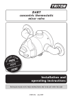
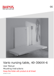
INSTALLATION AND LOCATION
The compressor must be run with the rubber feet resting on a flat and stable
horizontal surface.
The air compressor must be used in a clean and well-ventilated area. The compressor requires an unobstructed airflow and must be located a minimum of 20
inches from any walls or other obstructions that may prevent proper ventilation.
DO NOT place air compressor in an area:
• Where there is evidence of oil or gas leaks.
• Where flammable gas vapors or materials may be present.
• Where air temperatures fall below 32º F (0º C) exceed 104º F (40º C).
• Where extremely dirty air or water could be drawn into the air compressor.
Serious injury or death may occur if electrical sparks
from motor and pressure switch come in contact with flammable vapors,
combustible dust, gases or other combustible materials. When using the
air compressor for spraying paint, place the air compressor as far away from
the work area as possible, using extra lengths of air hose to extend the working reach instead of extension cords.
8
GROUNDING INSTRUCTIONS
This product should be grounded. In the event of an electrical short circuit, grounding reduces the risk of electric shock by providing an escape wire for the electric
current. This product is equipped with a cord having a grounding wire with an
appropriate grounding plug. The plug must be plugged into an outlet that is properly installed and grounded in accordance with all local codes and ordinances.
UNGROUNDED AC OUTLET
GROUNDED AC OUTLET
GROUNDING ADAPTER
POWER CORD PLUG
GROUNDING PIN
GROUNDING PIN
POWER CORD PLUG
COVERPLATE
MOUNTING SCREW
GROUNDING
RIGID EAR
Improper installation of the grounding plug can result in a risk of electric
shock. If repair or replacement of the cord is necessary, do not connect the
grounding wire to either flat blade terminal. The wire with GREEN insulation
with or without yellow stripes is the grounding wire.
This product is for use on a nominal 120-volt circuit and has a three-prong grounding plug that looks like the plug illustrated in Figure 1. A temporary adapter similar to the adapter illustrated in sketch B (See Page 9) may be used to connect this
plug to a 2-pole receptacle as shown in illustration B when a properly grounded
outlet is not available. The temporary adapter shall be used only until a properly
grounded outlet (Illustration A) is installed by a qualified electrician. Tab for
grounding screw, lug, or similar part extending from the adapter must be connected to a permanent ground such as a properly grounded outlet box cover.
Whenever the adapter is used, it must be held in place by a metal screw.
The use of a GFCI outlet is strongly recommended. The third prong is to be
used to ground the tool and provide protection against electrical shock.
Never remove the third prong.
Check with a qualified electrician or serviceman if the grounding instructions
are not completely understood, or if in doubt as to whether the product is
properly grounded. Do not modify the plug provided. if it will not fit the outlet, have the proper outlet installed by a qualified electrician.
EXTENSION CORDS
THE USE OF AN EXTENSION CORD WITH THIS PRODUCT IS NOT RECOMMENDED as this can result in the loss of power to your air compressor which
can prevent the motor from starting or running properly. This can also cause
your fuse to blow or circuit breaker to trip. Running your air compressor on an
undersized extension cord will cause permanent damage to internal switches
and overheating of the electric motor. Use an additional length of air hose rather
than an extension cord.
If you must use an extension cord, it should be plugged into a GFCI found in circuit
boxes or protected receptacles. Use only UL listed 3-wire extension cords that have
a 3-blade grounding plug and a 3-slot receptacle that will accept the plug on the
product. Make sure your extension cord is in good condition. When using an extension cord, be sure to use one heavy enough to carry the current your product will
draw. Refer to the guide on the next page for minimum gauge required for extension cords.
EXTENSION CORD LENGTH
WIRE SIZE (AWG)
Up to 25 Feet
14
26 to 50 Feet
12
51 to 100 Feet
Do Not Use
Use only extension cords that are intended for outdoor use. These cords are identified by a marking “ACCEPTABLE FOR USE WITH OUTDOOR APPLIANCES, STORE
INDOORS WHEN NOT IN USE.” Examine extension cord before use. DO NOT USE
DAMAGED EXTENSION CORDS. Do not pull on cord to disconnect from receptacle;
always disconnect by pulling on plug. Keep cord away from heat and sharp edges.
Always shut OFF the air compressor AUTO/ON pressure switch before unplugging
the compressor. Always disconnect the extension cord from the receptacle before
disconnecting the product from the extension cord.
Avoid electrical shock hazard. Never use this compressor with a damaged or frayed electrical cord or extension cord. Inspect all
electrical cords regularly. Never use in or near water or in any environment
where electric shock is possible. To reduce the risk of electrocution, keep all
connections dry and off the ground. Do not touch the plug with wet hands.
10
Guard against electrical shock. Avoid body contact with grounded services such as
pipes, ovens, stoves, and refrigerator enclosures. If not properly grounded, this air
compressor can incur the potential hazard of light trickle shock, particularly when
used in damp locations. If electrical shock occurs, there is the potential of secondary hazard such as your hands contacting an operating air tool.
COMPRESSOR FEATURES
8
1
2
3
7
5
4
6
COMPRESSOR FEATURES
1. ON/OFF SWITCH: The compressor will only run when the switch is in the
ON/AUTO position. Once the tank has reached the desired preset pressure
(“cut-out” pressure), the pump motor will automatically shut off. While the
switch is in the ON/AUTO position, the pump motor will automatically turn back
on once the pressure in the tank drops below the minimum preset pressure
(“cut-in” pressure).
Do not leave the compressor unattended while the power
switch is in the on/auto position. Unplug power cord when not in use.
2. AIR TANK PRESSURE GAUGE: The tank pressure gauge provides a reading of
the air pressure inside of the compressor tank.
11
3. OUTLET PRESSURE GAUGE: The outlet pressure gauge provides a reading of
the air pressure at the outlet side of the regulator. This pressure is controlled by
the pressure regulator and is always less than or equal to the air tank pressure.
4. AIR COUPLER: The air coupler is preinstalled into standard 1/4 inch (.635 cm)
NPT (F) threads in the pressure manifold. Use PTFE thread-sealing tape on the
threads to make sure you have an airtight connection when replacing quick
connect coupler.
5. PRESSURE REGULATOR: The regulator allows you to select the amount of air
pressure that is output through the air hose into tools and accessories. Turn the
pressure regulator knob clockwise to increase discharge pressure, and counter
clockwise to decrease discharge pressure. Please refer to the air delivery
requirements of your tools for the proper pressure settings. NOTE: Be careful
not to overtighten pressure regulator knob when it “bottoms out” as this may
damage pressure regulator.
6. AIR TANK DRAIN VALVE: Moisture is produced whenever air is compressed. It
is critical to drain water from the air tank on this compressor frequently. If unit
is used only occasionally, tank should be drained after each use and prior to the
next use. To drain the tank, slowly open the tank drain fitting by turning counter
clockwise. Once all moisture has drained out, close the fitting securely.
NOTE: Air tank will not pressurize while drain valve is open.
7. SAFETY RELIEF VALVE: This compressor is equipped with a safety relief valve
that is designed to prevent system failures by relieving pressure from the system when the air pressure reaches a predetermined level. The safety relief valve
is preset by the manufacturer. DO NOT attempt to modify or remove the safety
relief valve.
8. CARRY HANDLE: Convenient handle for easy transport.
12