1
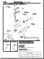
BACKUP
--- Service Manual
LASER
TALON
1991
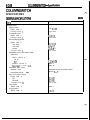
GROUP/SECTION
INDEX
Electrical .....................................
NOOAA-5
El
Fusible Liqk and Fuse Location .............
Inspection Terminal Location.. ................
Grounding Location ..............................
Diode Location ....................................
Junction Block .......................... . ......... .
Volume-Z
Electrical
Centralized Junction .............................
Inspection of Harness Connector ............
+ ‘.
FOREWORD
Troubleshooting ...................................
This Service Manual has been prepared with the
latest service information available at the time of
publication. It is subdivided into various group
categories and each section contains diagnosis,
disassembly, repair, and installation procedures
along with complete specifications and tightening
references. Use of this manual will aid in properly
performing any servicing necessary to maintain or
restore the high levels of performance and reliability
designed into these outstanding vehicles.
Configuration Diagrams .........................
Circuit Diagrams ..................................
”
Engine Electrical ...................... r.‘..........
Chassis Electrical ..................................
This BACKUP DSM manual IS to be used ONLY as a BACKUP. Please DO NOT REDISTRIBUTE
WHOLE SECTIONS. This BACKUP was sold to you under the fact that you do indeed OWN
a GENUINE DSM MANUAL. It CANNOT BE considered a REPLACEMENT (Unless your original
manual was lost or destroyed.)
Please See README.N or README.HTML for additional information
Thank you. G~mm~emymanual@hotma~l.com
-
Chrysler Corporation reserves the right to make changes in design or to
make additions to or improvements in its products without imposing
any obligations upon itself to install them on its products previously
manufactured.
0 1990 Mitsubishi Motors Corporation
Printed in U.S.A.
NOTE: For Engine, Chassis & Body,
refer to Volume-l
“Engine, Chassis & Body”.
m
8-2
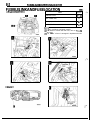
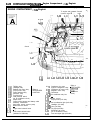
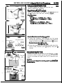
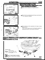
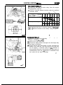
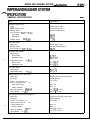
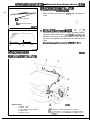
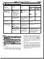
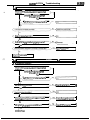
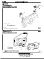
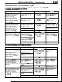
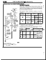
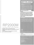
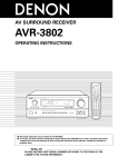
FUSIBLE LINK AND FUSE LOCATION
FUSIBLE LINK AND FUSE LOCATION
< Engine compartment >
Name
1
P
P:
Symbol
Dedicated fuses
0”; D
Main fusible links
A
Multi-purpose fuse block
E
Sub fusible links
. a--r
C
NVIE
: Air conditioner equipped models.
(1)
(2) For details of fusible link and fuse, refer to P.8-8, 9
and 10.
(3) The “Name” column is arranged in alphabetical order.
l
< Interior >
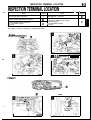
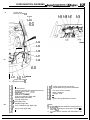
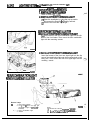
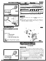
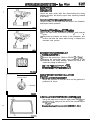
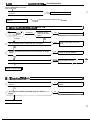
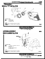
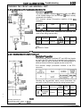
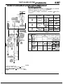
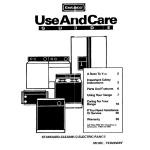
INSPECTION TERMINAL LOCATION
INSPECTION TERMINAL LOCATION
:’
1
.A-
Name
Symbol
Fuel pump check connector
A
Ignition timing adjustment connector
B
Oxygen sensor check connector
c2.OL DOHC Engine>
D
Name
Self-diagnosis connector.
E
Terminal for detecting the engine
revolution speed
<2.OL DOHC Engine>
C
NOTE
The “Name” column is arranged in alphabetical order.
< Engine compartment >
< 2.OL DOHC Engine >
for detecting the
engine revolution speed
3
I
< Interior >
\
16A0662
Symbol
8-4
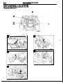
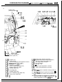
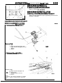
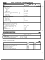
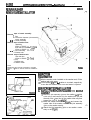
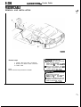
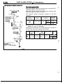
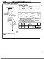
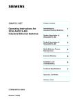
GROUNDING LOCATION
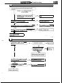
GROUNDING LOCATION
c Engine compartment >
GROUNDING LOCATION
< Interior-Front section >
/
10A0786
< Interior-Rear section and luggage compartment >
‘-.
NOTE
(1) *I: Vehicles with automatic seat belt
(2) **: Vehicles with ABS
&;$’
8-6
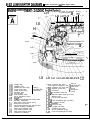
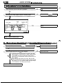
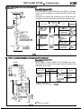
GROUNDING LOCATION/DIODE LOCATION
crossmember. front
IV\
/
18AO752,
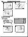
DIODE LOCATION
< Interior-Front section >
Name
Symbol
Diode (for ABS circuit)
D
Diode (for door ajar-warning circuit)
C
Diode (for pop-up circuit)
A
Diode (for theft-alarm circuit)
B
NOTE
The “Name” column is arranged in alphabetical order.
DIODE LOCATION
< Interior-Rear section >
8-7
8-8
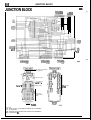
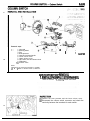
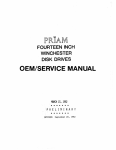
JUNCTION BLOCK
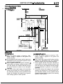
JUNCTION BLOCK
NOBBCJ (C-511
K IC-52)
G C-531
H GW
To engine compartment
wiring-harness
No connection
To instrument
oanel wiring
harness Theft-alam 7
horn relay
-Heater relay
Fuse block
(multi-purpose
fuses)
1610805
Remarks
(1) Same alphabets
in the diagram indicate the counterparts
of connectors.
(2) Terminals of the harness side connector are indicated in
parentheses ( 1.
To body wiring
iarness
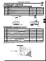
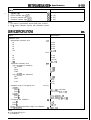
CENTRALIZED JUNCTION
CENTRALIZED JUNCTION
N08BB-
MAIN FUSIBLE LINK (direct connection to battery’s positive 0 terminal)
No.
Circuit
Housing color
Rated capacity @I
1
MPI circuit
Blue
20
2
Radiator fan motor circuit
Pink
30
3
Ignition switch circuit
Pink
30
4
ABS circuit
Yellow
60
<Vehicles without ABS>
-
<Vehicles with ABS>
SUB FUSIBLE LINK (relay box inside engine compartment)
Circuit
Housing color
1
Alternator circuit, sub fusible link 0, 0, @, 0, @
Black, Blue *
2
Defogger circuit
3
No.
--
Rated capacity (A)
80, 100”
Green
40
Automatic seatbelt circuit, dedicated fuse @ circuit
Pink
30
4
Pop-up circuit, Alternator circuit
Pink
30
5
Power window circuit
Pink
30
6
Multi- 6 urpose fuse 0, @, 0, @I, 0, @, 0, @, dedicated
fuse 4 circuit
Green
40
7
Headlight circuit, dedicated fuse 0, 0, @,circuit
Green
40
NOTE
* : <Vehicles for Canada>
Sub fusible links -
lOA
(
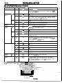
CENTRALIZED JUNCTION
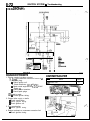
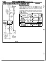
MULTI-PURPOSE FUSE (inside junction block)
Power supply circuit
Battery
Ignition
switch
IGs
ACC
Battery
Ignition
switch
IGs
ACC
No.
Rated capacity (A)
Load circuit
1
10
Automatic seatbelt control unit, key reminder switch, passing
control relay, seatbelt warning buzzer, taillight relay, theftalarm starter relay
2
-
-
3
10
Air conditioner control unit, air conditioner switch, defogger
timer, heater relay, power window relay, transistor relay*,
daytime running light relay 2*, ABS relay
4
10
Radio
5
15
Cigarette lighter, remote controlled mirror
6
15
Door lock relay, door lock control unit
7
IO
4-speed automatic transaxle control unit, auto-cruise control
unit <A/T>, combination meter
8
-
-
9
15
Intermittent wiper relay, wiper motor, washer motor
10
IO
Headlight relay, horn, theft-alarm control unit, daytime
running light relay 1
l
IGI
Battery
Ignition
switch
Battery
IGI
11
10
Auto-cruise control unit, auto-cruise control actuator
automatic seatbelt control unit, combination meter, theftalarm control unit, seatbelt timer*
12
10
Turn-signal and hazard flasher unit
13
-
-
14
10
Theft-alarm horn relay
15
-
-
16
30
Blower motor
17
15
Stop light
18
10
Back-up light <M/T>, dome light relay
19
10
4-speed automatic transaxle control unit, dome light,
door-ajar warning light, foot light, ignition key illumination
light, luggage compartment light, MPI control unit, radio,
security light, ABS relay
. .---
NWlt
x
: <Vehicles for Canada >
I
Multi-purpose
fuses
16A0805
8-1-I
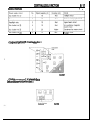
CENTRALIZED JUNCTION
,’
DEDICATED FUSE
Sub fusible link @
15
6
Blue
Foglight circuit
<Engine compartment R.H. side relay box>
16A0897
<Engine compartment L.H. side relay box
(air conditioner equipped models) >
Dedicaied fuse
16AOBSS
>
I
8-12
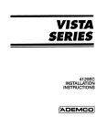
CENTRALIZED JUNCTION
CENTRALIZED RELAY
Engine
compartment
R.H. side
relay box
Name
Classification
Name
Classification
Engine
compartment
L.H. side
relay box
A-01X
Taillight relay
A-02X
Headlight relay
A-03X
Radiator fan motor relay
A-04X
Pop-up motor relay
A-05X
Power window relay
A-06X
Alternator relay
A-07X
Foglight relay
Interior
relay box
A-l 7X
Condenser fan motor highlow changeover relay
A-l 8X
Condenser fan motor relay
A-l 9X
Magnetic clutch relay
c-34x
Door lock relay
c-35x
Starter relay <M/T>
TJh$;larm starter relay
C-36X
Defogger timer
c-37x
Seatbelt timer*
C-38X
Daytime running light relay 1’
c-39x
Daytime running light relay 2’
NOTE
*: <Vehicles for Canada>
<Engine compartment R.H. side relay box>
<Engine compartment L.H. side relay box
(air conditioner equipped models) >
< Interior relay box >
c-34x
16A0897
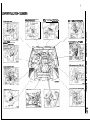
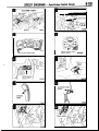
INSPECTION OF HARNESS CONNECTOR
8-13
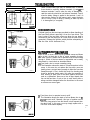
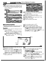
INSPECTION OF HARNESS
CONNECTOR
CONTlNUlTY AND VOLTAGE TEST FOR CONNECTOR
Following procedures shall be followed for testing conti&ty and
voltage at connector in order to prevent improper contact and
deterioration of waterproof in connector.
CONVENTlONAL (NON-WATERPROOF) CONN&TOR
Check shall be done by inserting a probing needle from harness
side.
WATER PROOF CONNECTOR
Caution
Do not insert probing needle from harness side as it will deterlorates waterproof and cause for rusting. To Inspect. the
energized circuit, use the ECI checker.
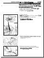
flCK FOR IMPROPER ENGAGEMENT OF TERMIWhen terminal stopper of connector is out of order, engagement
of male and female terminals becomes improper even when connector itself is engaged perfectly and terminal sometimes slips out
to rear side of connector. Ascertain, therefore, that each terminal
does not come off connector by pulling each harness wire.
ENGAGING AND DISENGAGING OF CONNECTOR
TERMINAL
Connector which gives loose engagement shall be rectified by
removing female terminal from connector housing and raise its
lance to establish securer engagement. Removal of “cpnnector
housing and raise its lance to establish securer engagement. Re
moval of connector terminal used for ECI and ELC 4 AIT control
circuit shall be done in the following manner.
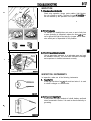
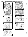
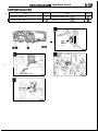
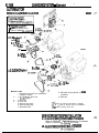
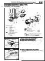
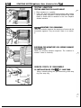
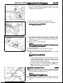
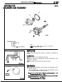
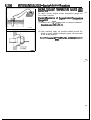
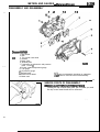
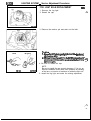
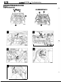
COMPUTER CONNECTOR
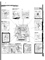
(1) Insert screwdriver Il.4 mm (.06 in.) width] as shown in the
figure, disengage front holder and remove it.
8-14
INSPECTION OF HARNESS CONNECTOR
(2) Insert harness of terminal to be rectified deep into connector
from harness side and hold it there.
(3) Insert tip of screwdriver [1.4 mm (06 in.) width] into connector
in a manner as shown in the figure, raise housing lance slightly
with it and pull out harness.
Housing lance
Caution
Tool No. 753787-l supplied by AMP can be used instead of
screwdriver.
16R1321
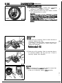
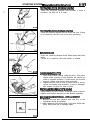
(4) Insert needle through a hole provided on terminal and raise
contact point of male terminal.
Needle
16R1322
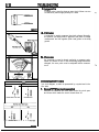
ROUND WATERPROOF CONNECTOR
(1) Remove waterproof cap by using a screwdriver.
(2) Insert tip of screwdriver [1.4 mm (.06 in.) or 2.0 mm (.08 in.)
width] into connector in a manner as shown in the figure, raise
housing lance slightly with it and pull out harness.
I
Housing lance
16R1323
(3) Insert screwdriver through a hole provided on terminal and
raise contact point of male terminal.
24
INSPECTION OF HARNESS CONNECTOR
8-15
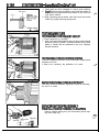
RECTANGULAR WATERPROOF CONNECTOR
(1) Disengage front holder by using a screwdriver and remove it.
(2) Insert tip of screwdriver (“0.8 mm (03 in.) width] into connector in a manner as shown in the figure, push it lightly to raise
housing lancer and pull out harness.
l lf right size screwdriver is not available, convert a conventional driver to suit the size.
Housing lance
16R132d
(3) Press contact point of male terminal down by holding a screwdriver [ 1.4 mm (06 in.) width] in a manner as shown in the
figure.
16R1329
INJECTOR CONNECTOR
(1) Remove waterproof cap.
16R1328
(2) Insert tip of screwdriver (1.4 mm (.06 in.) width] into connector
in a manner as shown in the figure, press in terminal lance and
pull out harness.
(3) Press contact point of male terminal down by holding a screwdriver [1.4 mm (.06 in.) width] in a manner as shown in the
figure.
Caution
Correct lancer to be in proper condition before terminal is
inserted into connector.
Termlnai lance
16Rl330
\
-
8-16
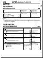
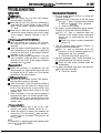
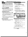
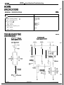
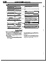
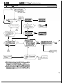
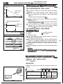
TROUBLESHOOTING
TROUBLESHOOTING
The most important point in troubleshooting is to determine “Probable Causes”. Once the probable causel’&
determined, parts to be checked can be limited to those associated with such probable causes. Therefore, Uhnecessary checks can be eliminated. The determination of the probable causes must be based on ‘B th$oqgn! ,b
.- I ,
supported by facts and must not be based on intuition only.
i. 1 ,._“‘I. ,,
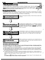
TROUBLESHOOTING STEPS
If an attempt is made to solve a problem without going through correct steps for troubleshooting, the problem
symptoms could become more complicated, resulting in failure to determine the causes correctly and making
incorrect repairs. The four steps below should be followed in troubleshooting.
1
Observe the symptom carefully. Check if there are also other
problems.
Observation of Problem Symptoms
I
2 Determination of Probable Causes
0
3
Checking of Parts Associated with
Probable Causes and Determination
of Faulty Parts
I
4 Repair and Confirmation
In determining the probable causes, it is necessary to check the
wiring diagram to understand the circuit as a system. Knowledge
of switches, relays and other parts is necessaty for accurate determination. The causes of similar problems in the past must be
taken into account.
Troubleshooting is carried out by making step by step checks until
the true cause is found. Always go through the procedures considering what check is to be made where for the best results.
After the problems are corrected, be sure to check that the system operates correctly. Also check that new problems have not
been caused by the repair.
INFORMATION FOR DIAGNOSIS
This manual contains the cable diagrams as well as the individual circuit drawings, operational explanations,
and troubleshooting hints for each component required to facilitate the task of troubleshooting. The
information is compiled in the following manner:
(1) Cable diagrams show the connector positions, etc., on the actual vehicle as well as the harness path.
(2) Circuit drawings show the configuration of the circuit with all switches in their normal positions.
(3) Operational explanations include circuit drawings of voltage flow when the switch is operated and how
the component operates in reaction.
(4) Troubleshooting hints include numerous examples of problems which might occur, traced backward in a
common-sense manner to the origin of the trouble. Problems whose origins may not be found in this
manner are pursued through the various system circuits.
NOTE
Components of ECI, ETACS. ECS, etc. with ECU do not include 3 and 4 above. For this information, refer
to a manual which includes details of these components.
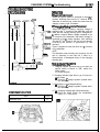
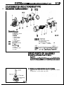
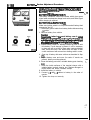
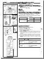
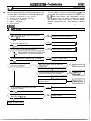
INSPECTION
1. Visual and aural checks
Check relay operation, blower motor rotation, light illumination, etc. visually or aurally. The flow of current is’invisible but
can be checked by the operation of the parts. ’
I.
2. Slmple checks
For example, if a headlight does not come on and a faulty fuse
or poor grounding is suspected, replace the fuse with.a new
one or ground the light to the body by a jumper wire to determine which part is responsible for the problem.
3. Checking with instruments
Use an appropriate instrument in an adequate range and read
the indication correctly. You must have sufficient knowledge
and experience to handle instruments correctly.
Changeover knob
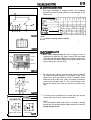
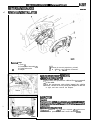
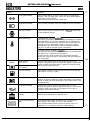
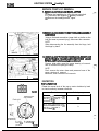
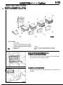
INSPECTION INSTRUMENTS
In inspection, make use of the following instruments.
1. Test lights
A test light consists of a 12V bulb and lead wires. It is used
to check voltages or shortcircuits.
16BO225
2. Self-power test light
A self-power test light consists of a bulb, battery and lead
wires connected in series. It is used to check continuity or
grounding.
-.
L
16D0226
8-18
TROUBLESHOOTING
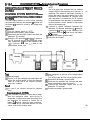
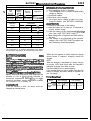
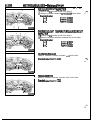
3. Jumper wire
A jumper wire is used to close an open circuit. Never use one
to connect a power supply directly to a load.
16BO227
4. Voltmeter
A voltmeter is used to measure the circuit voltage. Normally,
the positive (red lead) probe is applied to the point of voltage
measurement and the negative (black lead) probe to the body
ground.
Ground T
5. Ohmmeder
An ohmmeter is used to check continuity or measure resistance of a switch or coil. If the measuring range has been
changed, the zero point must be adjusted before measurement.
Normal
open (NO) type
OFF
ON
’ ill& -//j
Current does not flow
1)
Current flows
C u
Current
r r flows
e n t d o e s n;;I;Is
CHECKING SWITCHES
In a circuit diagram, a switch is represented by a symbol and in the
idle state.
1. Normal open or normal close switch
Switches are classified into those which make the circuit open
and those which make the circuit closed when off.
849
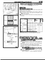
TROUBLESHOOTING
2. SWITCH CONNECTION
This figure illustrates a complex switch. The continuity
between terminals at each position is as indicated in the
,.
table below.
-.- -‘-J-stage
16A0253
Cover
Coil
Spring
Iron
core
Iron
piece .
I’ - ‘L
NOTE
o---O denotes continuity between terminals.
CHECKING RELAYS
1. When current flows through the coil of a relay, its core is
magnetized to attract the iron piece, closing (ON) the contact
at the tip of the iron piece. When the coil current is turned off,
the iron piece is made to return to its original position by a
spring, opening the contact (OFF).
,.
Contact
1600231
2. By using a relay, a heavy current can be turned on and off
by a switch of small capacity. For example, in the circuit
shown here, when the switch is turned on (closed), current
flows to the coil of the relay. Then, its contact is turned on
(closed) and the light comes on. The current flowing at this
time to the switch is the relay coil current only and is very
small.
Power supply
I
I
10AO254
I
Normal open (NO) type
Energized state
a
nml
Current does not flow
I
Current flows
16AO250
3. The relays may be classified into the normal open type and the
normal close type by their contact construction.
NOTE
The deenergized state means that no current is flowing
through the coil and the energized state means that current is
flowing through the coil.
8-20
TROUBLESHOOTING
Normal close (NC) type
i
Deenergized state
Current flows
I
Energized state
When a normal close type relay as illustrated here is checked,
there should be continuity between terminals (1) and (2) and
between terminals 3 and 4 when the relay is deenergized,
and the continuity should be lost between terminals 3 and 4
when the battery voltage is applied to the terminals 1 and 2. A
relay can be checked in this manner and it cannot be determine if a relay is okay or faulty by checking its state only when
it is deenergized (or energized).
Current does not flow
MAO257
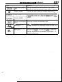
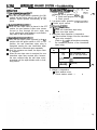
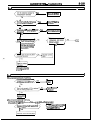
CHECKING FUSES
A blade type fuse has test taps provided to allow checking of
the fuse itself without removing it from the fuse block. The
fuse is okay if the test light comes on when its one lead is
connected to the test taps (one at a time) and the other lead is
grounded. (Change the ignition switch position adequately so
that the fuse circuit becomes live.)
1680235
State of fuse blown due to overcurrent
1680237
CAUTlONS IN EVENT OF BLOWN FUSE
When a fuse is blown, there are two probable causes as follows
: One is that it is blown due to flow of current exceeding its rating.
The other is that it is blown due to repeated on/off current flowing
through it. Which of the two causes is responsible can be easily
determined by visual check as described below.
(1) Fuse blown due to current exceeding rating
The illustration shows the state of a fuse blown due to this
cause. In this case, do not replace the fuse with a new one
hastily since a current heavy enough to blow the fuse has
flowed through it. First, check the circuit for shorting and
check for abnormal electric parts. Only after the correction of
such shorting or parts, fuse of the same capacity should be
used as a replacement. Never use a fuse of lager capacity than
the one that has blown. If such a fuse is used, electric parts or
wirings could be damaged before the fuse blows in the event
an overcurrent occurs again.
State of fuse blown due to thermal fatigue
(2) Fuse blown due to repeated current on/off
The illustration shows the state of a fuse blown due to re
peated current on/off. Normally, this type of problem occurs
after fairly long period of use and hence is less frequent than
the above type. In this case, you may simply replace with a
new fuse of the same capacity.
TROUBLESHOOTING
8-21
CHECKING CABLES AND WlRES
1. Check connections for looseness, rust and stains.
2. Check terminals and wires for corrosion by battery electrolyte,
etc.
3. Check terminals and wires for open circuit or impending open
circuit.
4. Check wire insulation and coating for damage, cracks and de
grading.
5. Check conductive parts of terminals for contact with other
metallic parts (vehicle body and other parts).
6. Check grounding parts to verify that there is complete continuity between attaching bolt(s) and vehicle body.
7. Check for incorrect wiring.
8. Check that wirings are so clamped as to prevent contact with
sharp corners of the vehicle body, etc. or hot parts (exhaust
manifold, pipe, etc.).
9. Check that wirings are clamped firmly to secure enough clearance from the fan pulley, fan belt and other rotating or moving
.
parts.
10. Check that the wirings between the fixed parts such as the
vehicle body and the vibrating parts such as the engine are
made with adequate allowance for vibrations.
HANDLING ON-VEHICLE BATTERY
When checking or servicing does not require power from the onvehicle battery, be sure to disconnect the cable from the battery
(-) terminal. This is to prevent problems that could be caused by
shorting of the circuit. Disconnect the (-) terminal first and reconnect it last.
Caution
1. Before connecting or disconnecting the negative cable, be
sure to turn off the ignition switch and the lighting switch.
(If this is not done, there is the possibility of
semiconductor parts being damaged.)
2. For MPI-equipped models, after completion of the work
steps [when the battery’s negative f-1 terminal is
connected], warm up the engine and allow it to idle for
approximately five minutes under the conditions
described below, in order to stabilize engine control
conditions, and then check to be sure that the idling is
satisfactory.
Engine coolant temperature: B5-95% (185-203OF)
Lights, electric fans, accessories: OFF
Transaxle: neutral position
(A/T models: “N” or “P”)
Steering wheel: neutral (center) position
8-22
TROUBLESHOOTING
TROUBLESHOOTING
Power supply
10A0200
Power supply
(Remove the fuse
lllumlnation
light
iii
T
16A0502
A circuit consists of the power supply, switch, relay, load, ground,
etc. There are various methods to check a circuit including an
overall check, voltage check, shortcircuit check and continuity
check. Each of these methods is briefly described in the following.
1. VOLTAGE CHECK
(1) Ground one lead wire of the test light. If a voltmeter is
used instead of the test light, ground the grounding side
lead wire.
(2) Connect the other lead wire of the test light to the
power side terminal of the switch connector. The test
light should come on or the voltmeter should indicate a
voltage.
(3) Then, connect the test light or voltmeter to the motor
connector. The test light should not come on, or the
voltmeter should.indicate no voltage. When the switch
is turned on in this state, the test light should come on,
or the voltmeter should indicate a voltage, with motor
starting to run.
(4) The circuit illustrated here is normal but if there is any
problem such as the motor failing to run, check voltages
beginning at the connector nearest to the motor until
the faulty part is identified.
2. CHECKING FOR A SHORT-CIRCUIT
Because the fuse has blown, it is probable that there is a
short-circuited circuit. Follow the procedures below to
narrow down the short-circuit location.
8-28
TROUBLESHOOTING
Continued from
previous page
Power supply
l‘est
ght-
w
Switch ON the switch.
(The test light illumi-
Fuse block
(Remove the fuse
nates but the illumination light does not.)
Switch
Short-clrcutt
Disconnect the load
l
llluminatlon
light
I
16A0503
YES +B
The test light re-
mains illuminated.
NO
I
switch and the
illumination
light. @I
Power supply
-est
lght
Fuse block
(Remove the fuse.)
Switch
Disconnect the load
Short-circuit
Illumination
light
16A0504
3. CHECKING CONTINUITY
(1) When the switch is in the OFF position, the self power
test light should come on or the ohmmeter should read
0 ohm only when the terminals 1 and 2 are interconnected.
(2) When the switch is the ON position, the self power test
light should come on or the ohmmeter should read 0
ohm only when the terminals 3 and 4 are interconnected.
Self power test light
(or ohmmeter)
16A0259
-
8-24
NOTES
CONFIGURATION
DIAGRAMS
CONTENTS
Dash Panel ......................................................
36
NOWA -.
Engine Compartment
<2.OL DOHC Engine (Turbo)> ..................... 32
Engine and Transaxle <1.8L Engine> ........ 34
How to Read Configuration Diagrams.. ...... 27
Engine and Transaxle
<2.OL DOHC Engine> ....................................
35
Instrument Panel and Floor Console .......... 39
40
Engine Compartment <1.8L Engine> ......... 28
Interior .............................................................
Engine Compartment
<2.OL DOHC Engine (Non-Turbo)> ............. 30
Overall Configuration Diagram ..................... 26
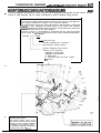
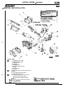
CONFIGURATION DIAGRAMS - Overall Configuration Diagram
OVERALL CONFIGURATION DIAGRAM
NOIVB-
License plate light
wiring harness
ABS wiring harness**
/
/
Instrument panel wiring harness
harness
harness <FWD >
Body wiring harness
Battery cable assembly
\
Engine room wiring harness
NOTE
(I) This illustration shows only the major wiring harness.
(2) *l Indicates also equipped at the right side.
(3) *2 indicates vehicles with ABS.
16A1226
CONFIGURATION DIAGRAMS - How to Read Configuration Diagrams 8-27
HOW TO READ CONFIGURATION DIAGRAMS
I.
NosvcAH
The wiring diagrams are prepared in such a way that the arrangement of connectors for each vehicle, and the
routing of each harness, can be easily understood for each individual wiring section.
Indicates the connector number.
The connector number used is the same number as that used for circuit diagrams;
these numbers facilitate the location of the connector positions.
The alphabet letter used as the prefix represents the wiring section in which that
sonnector is used; subsequent numerals make up the number that indicates
oarticular characteristics of that individual connector. As a general rule, numbers are
assigned clockwise around the wiring diagram.
Vote that, if there is a concentration of connectors with the same form (same
lumber of pins), the connnectors’ colors are noted in order to facilitate identification,
Example: A-l 2 (Black)
Connector color
Number indicating the connector’s
characteristics (series number)
Symbol indicating wiring section
location of the connector
A : Engine compartment
B: Engine and transaxle
C: Dash panel
D: Instrument panel and floor console
E : Interior
I
E-05 E-06 E-07 E-08 E-09 E-10 E-11 E-12 E-13
1)
\\\~\~'14‘;:"
-\\I
II
I
/
/
E-17
E-22
E-23
Indicates ground point.
The ground number used is the
same number as that used for circuit
diagrams; these numbers facilitate
the location of the ground points,
For detailed information concerning
ground points, refer to P.B-4.
8-28
CONFIGURATION DIAGRAMS - Engine Compartment <1.8L Engine>
ENGINE COMPARTMENT 4.8L Engine>
To engine and transaxle ‘Ground
(connector symbol q )
cable
A
3
A-10\
A-09
Connector
symbol
A-11
/ A-12
A-01X
A-d7X
-
Ground
ne and transaxle
A-47
A-46 ’
iiz
A-43
A-42
A-41
A-40
A-39
A-38
A-37
A-36
A-45
A-01X
A-02X
A-03X
A-04X
A-05X
A-06X
A-07X
A-08
A-09
A-10
A-l 1
A-12
A-13
A-14
A-15
A-16
Taillight relay
Headlight relay
Radiator fan motor relay
Refer to
Pop-up motor relay
CENTRALIZED
Power window relay
JUNCTION
Alternator relay
Fog light relay
Dual pressure switch
(for air conditioner circuit)
Wiper motor
Control wiring harness and battery cable
assembly combination
Auto-cruise control vacuum pump
Brake fluid level sensor
Purge control solenoid valve
EGR control solenoid valve
(Vehicles for California)
Refer to
Condenser fan motor
CENTRALIZED
high-low changeover relay
A-l 8X Condenser fan motor relay
?firNaYrTloN
A-l 9X Magnetic clutch relay
conditioner
A-20X Condenser
circuit)
A-2 1
A-22 t Air conditioner relay box
A-23
A-24 Washer motor
A-25
Pop-up motor (Left side)
A?C 1
i$y 1 Front combination light (Left side)
A-28
Headlight (Left side)
A-29
A-30 t Horn (Left side)
A-3 1
Fog light (Left side)
A-32
Condenser fan motor
(for air conditioner circuit)
A-33
Front turn-signal light (Left side)
A-l 7X
CONFIGURATION DIAGRAMS - Engine Compartment <I& Engine>
8:gg
To dash panel
(connector symbol El)
A-55
A-l 7X
A-56
A-57
A-14
A-:0X
_ A-21
1 A-22
A-24
A-25
A-26
yA-27
- - - - - - - A-28
A-29
1 A-30
I
A-33
\
A-32
\
A-31
36A0168
ITo engine and transaxle
(connector symbol a)
>.A
A-34
A-35
A-36
Air flow sensor
A-37
Automatic transaxle fluid temperature sensor
A-38
Kickdown servo switch <A/T>
A-39
Pulse generator <AA>
A-40
Radiator fan assembly
A-4 1
Front turn-signal light (Right side)
A-42
Radiator water level switch
A-43
Fog light (Right side)
A-44
A-45 t Horn (Right side)
A-46
Headlight (Right side)
A-47
A-48 I Front combination light (Right side)
A-49
Pop-up motor (Right side)
A-50
A-51
Control wiring harness and engine
A-52
A-53 t compartment wiring harness combination
A-54
Fuel pump check connector
A-55
A-56
Noise condenser
A-57
Defogger relay
A-58
A-59
A-60
Ignition timing adjustment connector
Remarks
(I) The mark * shows the standard mounting position of
wiring harness.
(2) For details concerning the ground point ‘(example: a).
refer to P.8-4.
(3) 1(-11 means that the connector with code-number is not
used.
8-30 CONFIGURATION DIAGRAMS -
Engine Compartment <Z.OL DOHC Engine (Non-Turbo)>
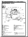
ENGINE COMPARTMENT <2.OL DOHC Engine (Non-Turbo)>
To engine and transaxle
(connector sympol q )
A-01X
Connector
symbol
A-&X A-gBx2 A-09 A-08”’ - A-IO\
I
Ground
A-11 cab!e
A-12
A
Ground cable
(connector symbol q )
IL-
A-47
A-44
A-45
A-01X Taillight relay
\
A-02X Headlight relay
A-03X Radiator fan motor relay
Refer to
A-04X Pop-up motor relay
CENTRALIZED
A-05X Power window relay
JUNCTION
A-06X Alternator relay
A-07X Fog light relay
A-08
Dual pressure switch
(for air conditioner circuit)
A-09
Wiper motor
A-10
Control wiring harness and battery cable
assembly combination
A-l 1
Auto-cruise control vacuum pump
A-12
Brake fluid level sensor
A-13
A-14
Purge control solenoid valve
A-15
EGR control solenoid valve
A-l 6
(Vehicles for California)
A!43
A-142
A-&
A!40
A!39
d-38
d-37
A-36 AZ
A-35
Refer to
Condenser fan motor
CENTRALIZED
high-low changeover relay
JUNCTION
A-l 8X Condenser fan motor relay
(for air
A-l 9X Magnetic clutch relay
conditioner
A-20X Condenser
circuit)
A-2 1
Air
conditioner
relay
box
A-22 I
ABS front speed sensor (Left side)
A-23
A-24 Washer motor
A-25
Pop-up motor (Left side)
A-26
A-27 I Front combination light (Left side)
A-28
Headlight (Left side)
A-29
Horn
(Left side)
A-30 I
A-3 1
Fog light (Left side)
Condenser fan motor
A-32
(for air cond,itioner circuit)
A-33
Front turn-signal lrght (Left side)
A-l 7X
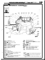
CONFIGURATION DIAGRAMS - E ngine
dash panel
(connector symbol fl)
8131
Compartment <2.OL DOHC Engine (Non-Turbo)>
To
I ,
A-55
A-56
A-57
A-14
A-59
I A-l 7X
A-21
- A-22
I
,
:\
A-23
A-60
A-116
36AO172
I A-29
A-30
A-33
\
A-32
\
WA0172
A-31
1T o e n g i n e a n d t r a n s a x l e
(connector symbol q )
A-34
A-35
A-36
A-37
A-38
A-39
A-40
A-4 1
A-42
A-43
A-44
A-45
A-46
A-47
A-48
A-49
A-50
A-51
t
Hydraulic unit
Air flow sensor
Automatic transaxle fluid temperature sensor
Kickdown servo switch <A/T>
Pulse generator <A/T>
Radiator fan assembly
Front turn-signal light (Right side)
Radiator water level switch
Fog light (Right side)
Horn (Right side)
Headlight (Right side)
Front combination light (Right side)
Pop-up motor (Right side)
-
Control wiring harness and engine
A-52
A-53 t compartment wiring harness combination
A-54
ABS front speed sensor (Right side)
A-55
Fuel pump check connector
A-56 Noise condenser
A-57
Defogger relay
A-58
A-59
Engine speed adjustment connector
A-60
Ignition timing adjustment connector
Remarks
(1) The mark * shows the standard mounting position of
wiring harness.
(2) For details concerning the ground point (example: m,
refer to P.84.
( 3 ) ‘I-” means that the connector with code-number is not
used.
(4) The wiring indicated by the *I symbol is applicable to
vehicles with ABS and the wiring indicated by the +2
symbol is applicable to vehicles Gthout ABS.
J
8-32
CONFIGURATION
ENGINE
DIAGRAMS
-
Engine Compartment <2.OL DOHC Engine (Turbo)>
TMENT <2.OL DOHC Engine (Turbo)>
To engine and transaxle
(connector symbol ail)
A-01X
I
A-09
Connector
symbol
A-O8*3
Ground
cabje
A-IO
A-53
A-52
A-5 1
\
Ground
To ‘engine and transaxle
(connector symbol n
-A-44
A-45
Taillight relay
Headlight relay
Refer to
Radiator fan motor relay
CENTRALIZED
Pop-up motor relay
Power window relay
JUNCTION
$0”;:: Alternator relay
A-07X Fog light relay
A-08
Dual pressure switch
.(for air conditioner circuit)
H-UY
Wiper motor
A-IO
Control wiring harness and battery cable
assembly combination
A-l 1
Auto-cruise control vacuum pump
A-12
Brake fluid level sensor
A-13
Control wiring harness and solenoid valve
harness assembly combination
A-14
Purge control solenoid valve
A-15
Fuel pressure solenoid valve
A-16
EGR control solenoid valve
(Vehicles for California)
A-01X
A-02X
A-03X
A-04X
A-43
A!42
A-l 7X
A-l 8X
A-l 9X
A-20X
A-21
A-22
A-23
A-24
A-25
A-26
A-27 I
A-28
A-29
A-30 I
A-3 1
A-32
I
A-33
A140 d-39 A-38 d-37 A-36
g
Refer to
Condenser fan motor
CENTRALIZED
high-low changeover relay
JUNCTION
Condenser fan motor relay
(for air
Magnetic clutch relay
conditioner
I
Condenser
circuit)
Air conditioner relay box
ABS front speed sensor (Left side)
Washer motor
Pop-up motor (Left side)
Front combination light (Left side)
Headlioht (Left side)
Horn (Left side)
Fog light (Left side)
Condenser fan motor
(for air conditioner circuit)
Front turn-signal light (Left side)
I *A
CONFIGURATION DIAGRAMS
- Engine Compartment <2.OL D&lC Engine (Turbo)>
&i33
To dash panel
(connector symbol q )
t
A-;3
A-14
1
A-55
\
A-56
\
A-57
I
A-58
I
A-59
I.
I A-2A-221
,
A-23
A-60
3SA0171
A-27
\ A-29
’ A-30
A-33
A-32
A-31
To engine and transaxle
- (connector symbol @I)
c
A-34
A-35
A-36
A-37
A-38
A-39
A-40
A-41
A-42
A-43
A-44
A-45
A-46
A-47
A-48
A-49
A-50
A-51
A-52
A-53
t
Hydraulic unit
Air flow sensor
Automatic transaxle fluid temperature sensor
Kickdown servo switch <A/l>
Pulse generator <AIT>
Radiator fan assembly
Front turn-signal light (Right side)
Radiator water level switch
Fog light (Right side)
~.
t Horn (Right side)
Headlight (Right side)
I Front combination light (Right side)
Pop-up motor (Right side)
Hood switch
Waste gate solenoid valve
Control wiring harness and engine
t compartment wiring harness combination
A-54
ABS front speed sensor (Right. side)
A-55
Fuel pump check connector
A-56 Noise condenser
Defogger relay
A-57
A-58 R e s i s t o r
A-59
Engine speed adjustment connector
A-60
Ignition timing adjustment connector
$m??mark Ir shows the standard mounting position of
wiring harness.
(2) For details concerning the ground point (example: ai,
refer to P.8-4.
(3) The wiring indicated by the *t symbol is applicable to
vehicles with the theft-alarm system and the wiring
indicated by the +2 symbol is applicable to vehicles
without the theft-alarm system.
(4) The wiring indicated by the *3 symbol is applicable to
vehicles with ABS and the wiring indicated by the *4
symbol is applicable to vehicles without ABS.
8-34
CONFIGURATION DIAGRAMS - Engine and Transaxle <1.8L Engine>
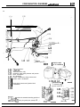
ENGINE AND TRANSAXLE <1.8L Engine>
B-o2
Bmoz\B-O\
B-r
B-r
To engine compartment
I
( c o n n e c t o r s y m b o l i&l) L\ b&
\\
f&z-l
B-26 \ v
Bi”
I
I
I
~-‘,
7””
I
I
I
1
II
-m
To engine compartment
-------BY%
/j
(connector symbol @I) y-
B-l 6
- B-21
----
/
\
B-22
/
B-23
36A0170
B-01
B-02
B-03
B-04
B-05
B-06
B-07
B-08
B-og
Injector No. 4
B-22
Throttle position sensor
Motor position sensor
Idle speed control actuator
Injector No. 3
EGR temperature sensor
(Vehicles for California)
Injector No. 2
Injector No. 1
CRC filter
B-23
B-24
B-l 0
B-l 1
B-l 2
B-l 3 I Distributor assembly
B-14
B-15
B-16
Magnetic clutch (for air conditioner circuit)
B-l 7
B-l 8
Power steering oil pressure switch
B-l 9 I Alternator
B-20
B-21
oil pressure switch
B-25
B-26
B-27
B-28
B-29
EIUy
B-32
Oil pressure gauge unit
Back-up light switch <M/T>
4-speed automatic transaxle control solenoid
valve
Inhibitor switch
Oxvaen s e n s o r
‘Starter motor
I
Engine coolant temperature gauge unit
Engine coolant temperature sensor
1
Remarks
(1) The mark + shows the standard mounting position of
wiring harness.
(2) For details concerning the ground point (example: q ),
refer to P.8-4.
(3) “-‘I means that the connector with code-number is not
used.
CONFIGURATION DIAGRAMS -
w35
E ngine and Transaxle <2.OL DOHC Engine>
ENGINE AND TRANSAXLE <2.OL DOHC Engine>
n
Connector
symbol
B
To engine compartment
(connector symbol q )
B-l 5
B-l 6
B-l 7
B-28
B-27
B-26 -
B-l 8
B-l 9
To engine compartment
(connector symbol q )
B-25,
compartment
symbol f&f)
\
B-20
/
B-24 ’
71 -J--
B-21
\
,22
/
36AOlS9
B-23
B-01
B-02
B-03
B-04
B-05
B-06
B-07
B-08
B-0g
B-l 0
Injector No. 4
Throttle position sensor
Idle speed control actuator
Idle switch
Injector No. 3
Detonation sensor <2.OL DOHC turbo>
EGR temperature sensor
(Vehicles for Californra)
Injector No. 2
Injector No. 1
B-l 4
Ignition coil
B-15
Power transistor
B-l 6
Magnetic clutch (for air conditioner circuit)
B-l 7
Power steering- oil pressure switch
B-18
Alternator
B-l 9 I
B-20
Engine compartment wiring harness and
engine wiring harness combination
Oil pressure switch
B-21
Oil pressure gauge unit
Back-up light switch tMiT>
4-speed automatic transaxle control solenoid
valve
Inhibitor switch
B-25
B-26 Oxygen s e n s o r
B-27
- motor
Starter
B-28 I
B-29
Engine coolant temperature gauge unit
B-30
Engine coolant temperature sensor
B-31
Engine coolant temperature switch
B-32
(for air conditioner circuit)
Crank angle and top dead center sensor
B-22
B-23
B-24
Remarks
(1) The mark + shows the standard mounting position of
wiring harness.
(2) For details concerning the ground point (example: q ),
refer to P.8-4.
( 3 ) “_” means that the connector with code-number is not
used.
8-36
CONFIGURATION DIAGRAMS - Dash Panel
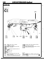
DASH PANEL
h
Connector
symbol
-01
I
C
c-03
C-04
C-05
C-06
C-07
229 228
C-27
C-98
c-09
c-,I 0
-E
I
g;::
c-37x
C-36X
c-35x
c-34x
To interior
(connector symbol
C
/
\
c-30
To interior
(connector symbol 0)
\
To inkrument panel
and floor console
(connector symbol
Auto-cruise control unit or jumper connector
c-02
c-03 I Stop light switch
c-01
c-04
Ez
C-24
To instriment panel
I)
and floor console
(connector symbol lI%
C-23
C-24 I Radio
:I;;
Theft-alarm starter relay <M/T>
Floor console wlrmg harness and body wiring
Ignition switch
c-05
Kev reminder switch
C-06
’
Column
switch
c-07 I
C-08
Accelerator pedal switch <A/T>
C-09 Blower switch
EI; y
Air conditioner switch
Blower resrstor
C-l 2
Air conditioner wiring harness and bodywiring
harness combination
C-l 3
Diode (for pop-up circuit)
C-14
Transistor relay (for daytime running light
circuit)
c-15
Foot light (Right side)
C-l 6
Body wiring harness and ABS wiring harness
C-l 7t combination
C-18
Door lock control unit
c-19
c-20 t Theft-alarm control unit
c-21
Blower motor high relay (vehicles with an air
conditioner) or jumper connector
c-22
Blower motor
q
/
c-25
C-27
C-28
C-29
harness combination
Buzzer
Clutch medal switch (for starter circuit) <M/T>
$!~~~edal switch (for auto-cruise circuit)
E113y Self-d,iagnosis c o n n e c t o r
Foot light (Left srde)
C-32
Turn-signal and hazard flasher unit
C-33
Diode (for theft-alarm system or daytime
running light circuit)
c-34x Door lock relay
c-35x Starter relay <M/T> or
theft-alarm starter
relay <A/T>
Refer to
C-36X Defogger timer
CENTRALIZED
c-37x Seatbelt timer
IUNCTION
(without automatic seatbelt)
C-38X Daytime running light relay 1
Daytime running light relay 2
::;;x Air conditioner control unit
c-41
Air inlet sensor
L
8137
CONFIGURATION DIAGRAMS - Dash Panel
symbol
^ a-
q
)
C-16
z-22
c-21
To i\nterior
(connector symbol
q
)
Vehicles with
[ an air conditioner
36AO137
Air therm0 sensor
Heater relay
Theft-alarm horn relay
Instrument panel wiring harness and junction
block combination
No connection
Engine compartment wiring harness and
junction block combination
C-42
c-43
c-44
c-45
C-46
c-47
C-48
c-49
c-50
c-51
C-52
c-53
c-54
c-55
1
c-12
Body wiring harness and junction block
combination
I
~;?mTa~keSmark * shows the standard mounting position of
wiring harness.
(2) For details concerning the ground point (example: q ),
refer to P.8-4.
c-42 6-41
[Junction block I
-
, To instrument panel
(connector symbol q )
C-48
c-47
C-46
c-451
c-44
c-55
c-54
c-53
c-43
Front side)
16A0903
(Rear side)
36AOOJl
8-38
CONFIGURATION DIAGRAMS - Dash Panel
DASH PANEL
C
Ll
Connector
symbol
-56
-:“3
c-7 1
C-72
c-73
C-56
C-56
EG
c\-68
c-67
c-70
C83
GE
C-61
C-62
EG
C-58
c-59
Oxygen sensor check connector
<2.OL DOHC engine >
Control wiring harness and body wiring
harness combination
Instrument panel wiring harness and body
C-69
C-70 I wiring harness combination
c-7 1
Engine compartment wiring harness and body
C-72
wiring harness combination
c-73
harness combination
Instrument panel wiring harness and engine
Remarks
(1) The mark + shows the standard mounting position of
wiring harness.
(2) For details concerning the ground point (example: a),
refer to P.84.
c-57
C-58
c-59
C-60
C-61 1 4-speed automatic transaxle control unit
C-62
J
C-63
MPI control relav
C-64 I
C-65
MPI control unit
C-66
C-67
Control wiring harness and body wiring
C-68
G-4
C-65
C-66
compartment wiring harness combination
CONFIGURATION DIAGRAMS - Instrument Panel and Floor Console
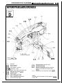
8-m
INSTRUMENT PANEL AND FLOOR CONSOLE
D-l 1
D-09
D-08
D-O<
D-01
.
\xx
I
Refer to d&h panel
(connector symbol m)
D-O 1
Rheostat
D-02
Fog light switch
D-03
Pop-up switch
D-04
Front speaker (Left side)
D-05
D-06 1 Combination meter
E:Nz
Heater control panel illumination light
Rear wiper and washer switch
D-09
Defogger switch
D-IO
Hazard switch
D-l 1
Front speaker (Right side)
D-l 2
Glove compartment light
D-l 3
Glove compartment light switch
D-l 4
Ashtray illumination light
D-18
D-l 5
:I~?
D-l 8
D-l 9
I
D-l 7
\
D-l 6
36A0166
Cigarette lighter illumination light
Cigarette lighter (+)
Cigarette lighter (-1
Overdrive switch and automatic transaxle
selector lever position illumination light
4J-b
Power/Economy changeover switch <A/T>
Remark
The mark * shows the standard mounting position of
harness.
Wiring
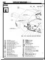
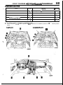
CONFIGURATION DIAGRAMS - Interior
8-40
NTERIOR
E-01
E-03
E-02
E-04
Connector
symbol
E
To dash panel
(connector symbol
q
)
E-55
E-56
E-01
gg
E-04
E-05
E-06
E-07
E-08
E-09
E-l 0
E-l 1
E-l 2
E-l 3
E-14
E-l 5
E-l 6
E-l 7
E-l 8
E-l 9
E-20
E-2 1
Dome light
Door speaker (Right side)
Door mirror (Right side)
Power window motor (Right side)
Power window sub-switch
Outer switch (for automatic seat belt)
Door latch switch (Right side)
(for automatic seat belt)
Door key cylinder unlock switch (Right side)
(for theft-alarm system)
Door lock actuator (Right side)
Door switch (Right side)
ABS power relay
ABS control unit
Diode (for ABS circuit)
Resistor (for ABS circuit)
Rear speaker (Right side)
Defogger (-)
Rear wiper motor
High-mounted stop light
Rear combination light (Right side)
Rear side marker light (Right side)
Rear combination light (Right side)
E-22
E-54
E-53
,E-52
E-51
E-50
Liftgate unlock switch
(for theft-alarm system)
E-23
Liftgate latch switch
E-24
Liftgate switch
(for theft-alarm system)
E-25
Back-up light (Right side)
E-26
E-27 1 License plate lights
E-28
Back-up light (Left side)
E-29
License plate light wiring harness and body
wiring harness combination
E-30
Rear combination light (Left side)
E-31
Rear washer motor
E-32
Rear combination light (Left side)
E-33
Fuel pump and gauge assembly <AWD>
E-34
Rear side marker light (Left side)
E-35
E-36
5 sensor (for ABS circuit)
E-37
ABS rear speed sensor (Right side)
E-38
Luggage compartment light
E-39
ABS rear speed sensor (Left side)
E-40
Rear speaker (Left side)
E-41
Automatic seat belt control unit
E-49
849
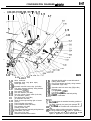
CONFIGURATION DIAGRAMS - Interior
E;05 E-r)6 E-y7 E-y8 E-09 E-10 E-1 1 E-,l2 E-13
\
E-14
E-15
\\\I I l-i- I
E-y 6
\ K\I
//
E-19
*E-20
\ //E-21
I
E-47
36AO165
E-48
E-43 g42 E-\41 E-40
E-42
Noise condenser
E-43
Intermittent wiper relay (Rear wiper)
E-44
E-45
E-46
E-47
Dome light relay
Automatic seat belt motor relay (Left side)
Fuel wiring harness and body wiring harness
combination <FWD>
Door switch (Left side)
E-48
Door lock actuator (Left side)
E-49
Door key cylinder unlock switch (Left side)
E-50
(for theft-alarm system)
Door latch switch (Left side)
E-51
(for automatic seat belt)
Diode (for door-ajar warning light or buzzer
E-52
circuit*)
Power window main switch
E-53
Power window motor (Left side)
E-54
Door speaker (Left side)
E-55
Passing control relay
E-56
Door wiring harness and body wiring harness
E-57
E-58 I combination (Left side)
E-59
Door mirror (Left side)
Remote controlled mirror switch
E-60
E-61
E-62
E-63
E-64
E-65
E-66
E-67
E-68
E-69
E-70
E-71
Seat belt buckle switch or seat belt switch*
Parking brake switch
Door wiring harness and body wiring harness
combination (Right side)
Automatic seat belt motor relay (Right side)
Defogger (+I
Fuel gauge unit <FWD>
Fuel pump <FWD>
Liftgate wiring harness and body wiring
harness combination
~~m%~mark * shows the standard mounting position of
wiring harness.
(2) For details concerning the ground point (example: q 3,,
refer to P.8-4.
(3) fl-” means that the connector with code-number is not
used.
(4) * indicates vehicles without automatic seat belt.
(5) The wiring indicated by the *l symbol is applicable to
vehicles with ABS and the wiring indicated by the *2
symbol is applicable to vehicles without ABS.
8-42
NOTES
CIRCUIT DIAGRAMS
CONTENTS
Air Conditioner Circuit ................................
99
44
Anti-Lock Braking System Circuit .............. 111
Ignition Circuit ..............................................
171
Audio Circuit .................................................
270
Indicator Light Circuit ..................................
200
Auto-Cruise Control Circuit .........................
121
Meter and Gauges Circuit ..........................
196
Automatic Seat Belt Circuit .......................
105
MPI Circuit . . . . . . . . . . . . . . . . . . . . . . . . . . . . . . . . . . . . . . . . . . . . . . . . . . ~
Back-Up Light Circuit ..................................
230
Pop-Up Mechanism Circuit . . . . . . . . . . . . . . . . . . . . . . . . .
225
Buzzer Circuit ................................................
109
Power Distribution Circuit ,,.~,..........~.......,..
49
Central Door Locking Circuit ......................
95
Power Window Circuit . . . . . . . . . . . . . . . . . ..a............
86
Charging Circuit ............................................
143
Rear Wiper and Washer Circuit ................. 255
Cigarette Lighter Circuit ..............................
267
Remote Controlled Mirror Circuit ..............
104
Cooling Circuit ..............................................
84
Starting Circuit .............................................
154
Defogger Circuit ...........................................
297
Stop Light Circuit ........................................
234
Dome Light, Ignition Key Illumination Light,
Foot Light, Glove Compartment Light and
Luggage Compartment Light Circuit ......... 228
ELC 4-Speed Automatic Transaxle
Circuit .............................................................
Y
How to Read Circuit Diagrams ..................
NOWE-
89
Fog Light Circuit ..........................................
222
Headlight Circuit ...........................................
213
Heater Circuit ................................................
98
Horn Circuit ...................................................
264
52
Taillight, Position Light, Side Marker Light
and License Plate Light Circuit . . . . . . . . . . . . . . . . . . 227
Theft-alarm Circuit . . . . . . . . . . . . . . . . . . . . . . . . . . . . . . . . . . . . . . .
130
Turn Signal Light and Hazard Light
Circuit . . . . . . . . . . . . . . . . ..*.*........................................
231
Warning Light Circuit .,............................#...
198
Windshield Wiper and Washer Circuit ,.-, 253
8-44
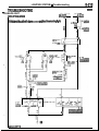
CIRCUIT DIAGRAMS - How to Read Circuit Diagrams
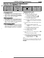
HOW TO READ CIRCUIT DIAGRAMS
NOSVFAG
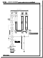
The circuit of each system from the fuse (or fusible link) to ground is shown. The power supply is shown at
the top and the ground at the bottom to facilitate understanding of how the current flows.
Indicates connector No.
The same No. as in the
wiring harness diagram is
used.
Indicates power takeout.
\
ly
SUB F IBLE
LINK e
5
i?l
c;
1.25BR
I
I
If the same connector is
shown
-..-.-. at two or more
locatrons, the connector
is indicated by 25 with
connector symbol shown
I
I
An “X” at the end of a
connector No. indicates
that the connector is connected to a centralized
junction that is shown in
the section “Centralized
Junction”.
\
BENBOR
c-10
Indicates the operating,
conditions of the engine
coolant switch, etc.
@
Indicates that the diagram
is continued at 7 on the
next page.
I
-
-
I
x
CIRCUIT DIAGRAMS - How to
Read
Circuit Diagrams
8-45
Indicates that the diaram is continued from
b on the previous
page.
I
-1
‘23
d
mm--) ---_______----__------ - - - - - - %52
..d
Y
Indicates input/output to/from
I
-
--
\
Indicates J/B (Junction Block).
y-g$s&]
Indicates vehicle body ground
Indicates that the terminal is a
CIRCUIT DIAGRAMS - How to Read Circuit Diagrams
CONNECTOR/GROUND INDICATIONS
REE ITOR
7
$UOIpO
A-12
I
I
G!l
CIRCUIT DIAGRAMS -
HOW
to Read Circuit Diagrams
the equipment is shown; for intermediate
connectors, the symbol for the connector at the
male side is shown.
‘I
CIRCUIT DIAGRAMS - How to Read Circuit Diagrams
8-48
SYMBOLS
Devices appearing in circuit diagrams are indicated by the following symbols.
Battery
Body ground
Single bulb
Resistor
Diode
Capacitor
Fusible link
ECU interior
ground
Speaker
~
j
Coil
Transistor
with
Crossing of wires
cortron
Connector
Motor
Horn
Pulse generator
Buzzer
Chime
Thyristor
Piezoelectric
device
Thermistor
Light emitting
Photo diode
Photo transistor
j+
-loI16AO252
WIRE COLOR CODES
Wire colors are identified by the following color codes.
Examole:
1.25F-GB
LG: Basic color
B: Marking color
1600244
1.25:Wire size (mm*)
F: Flexible wire
T:Twisted wire
(1) No code indicates 0.5 mm2 LOO08 in.‘).
(2) Cable color code in parentheses indicates
0 . 3 mm* (.0005 in.*).
NOTE
If a cable has two colors, the first of the two color code characters
indicates the basic color (color of the cable coating) and the second
indicates the marking color.
8-49
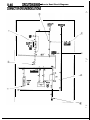
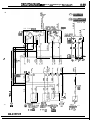
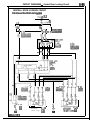
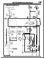
CIRCUIT DIAGRAMS - Power Distribution Circuit
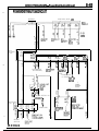
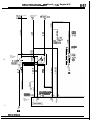
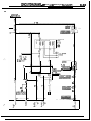
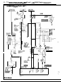
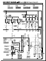
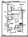
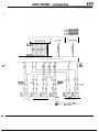
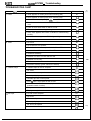
POWER DISTRIBUTION CIRCUIT
VEHICLES WITH ABS
BATTERY
SUB
FUSIBLE
LINK
Q
1,
0
SOA
lOOAX'
:‘:
m
il
ik
v*
ALTERNATOR
(B-TERMINAL)
*
i3EEKGER
EE:
CL
@
0
0.3
30A
30A
40A
5
cl
5.i
L:
7 ?
Y
cu %I
Ku
V
AUTOMATIC
SEATBELT
MOTOR
RELAY
V
ALTERNATOR
(S-TERMINAL)
REP
RELAY
DEDICATED
FUSE
0
10A
c
HAZARD
SWITCH
K35-AC-U0104-NC
62
idI zc3
ki COLUMN SWITCH OR
,GROUND*'
62
+
CL
ki
A-22
lea
466
Ii3
V
HEADLIGHT
I
POWER
WINDOW
RELAY
CONDENSOR
;;rJAyOTOR
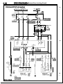
CIRCUIT DIAGRAMS - Power Distribution Circuit
8-50
,,,&USIBLE
fXJ;k--;UISE
UNIT(A/T)
*INHIBITOR
SWITCH(A/T)
'STARTER
RELAY(M/T
%X~EfiLA b M
RELAY(A/T)
1
I
c-i
*RADIATOR
FAN MOTOR
.!%&NSER FAN
MOTOR RELAY
.IGNITION COIL
.MPI CONTROL
.pAf~~~OR
WWA$ONTROL
*POWER
TRANSISTORI'
J/B
IULTI-PURPOSE FUSE
;;Ml;NATION
m
125.4
ss-fa
I c-54
7
,. ----------___------------~~~~~
/\
V
.DOME LIGHT
.iM&M4+i~~
.~~';'~~ITOR SWITCH
;;EfiQJig;U16E
WITCH
f UTOMATIC
SEATBELT CONTROL
UNIT
THEFT-ALARM
CONTROL UNIT
I
HAZAD
mxW%'
BWITCH
*DEFOGGER TIMER
.DEFOGGER EWITCH
.POWER WINDOW
.&& GWITCH
.HEATER RELAY
.;$fJf3;~'0"
*DAYTIME RUNNING
LIGHT RELAYPXl
.fi;.4A;OWER
E
TE
.OVER DRIVE GWITCH
'EE
*AUTO-CRUIEE
.REMOTE
CONTROL
CONTROL UNIT
MIRROR BWI TCH
*INHIBITOR BWITCH
.POWER/ECONOMY
CHANGE OVER
4
I
*!f$%fi~T
*INTERMITTENT
RADIO
WIPER
RELAY
!s ARNING)
.WIPER AND
.l"Sf~~~R&p
REMARKS
(3) THE ABOVE CIRCUIT DIAGRAM SHOWS THE CURRENT FLOW AT THE IGNITION KEY
POSITIONS "ACC", "ON" AND "ST" COMBINED.
(2) ~~s~ESP;NTRACE THE APPROPRIATE CIRCUIT DEPENDING ON THE IGNITION KEY
(3) %l:VEHICiES FOR CANADA.
(4) :P:VEHICLES WITH THEFT-ALARM SYSTEM.
*THEFTk!k!~;;
f?'i'tffjNG
RELAY181
'HORN
e
--
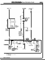
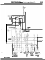
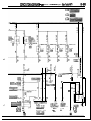
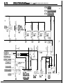
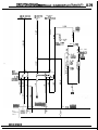
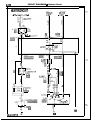
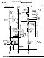
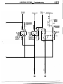
CIRCUIT DIAGRAMS - Power Distribution Circuit
SUB FUSIBLE
LINKQ
:DICA1I'ED
JSEO
Q
C
&
r
1
z?L+'GHT
A-01X
34
El
FRONT
COMBINATION
LIGHT
1
5.-------------------------------.
J
a3 r0 -63
i! PA _-_Y-...,
T
-48
_-_
.RE R
COII BINATION
LIGHT
DOOR LOCK RELAY
Q?;I?E);;AT
1
BWITCil
.COLUMN SWITCH
(LIGHTING BWITCH)
Hsw%
THEFT-ALARM
'~;~T~~MINDER
HORN RELAY
.THEFT- LARM
GTARTE it! RELAY
REMARK
.%l:VEHICLES FOR CANADA.
KX35-AC-U0104A-NC
q
,,l c-47 B
1
J/B
-" MULTI-PURPOSE FUSE
CONTROL UNIT*IGNlTION KEY
ILLUMINATION
.k8iTLOCK
CONTROL UNIT
8-52
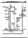
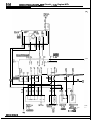
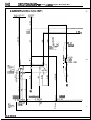
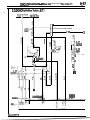
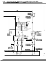
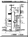
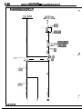
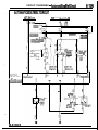
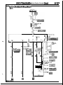
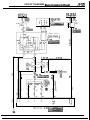
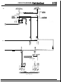
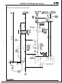
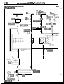
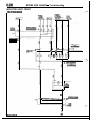
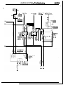
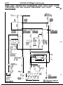
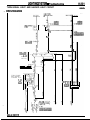
CIRCUIT DIAGRAMS - MPI Circuit <1.8L Engine-M/T>
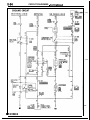
MPI CIRCUIT
1.8L Engine <M/T>
MAIN USIBLE
i%f
LINK 1-v
c-59
123
456
m
IGNITION
SWITCH(IG1)
?
cl:
2
r:
-----~ --______________________________^___
z
Fs
(:
pisg
A
E-47
FUEL
PUMP
E-69
?J;bKPUMP
:ONNEGTOR
MPI
CONTROL
RELAY
J-
2
1 C-63
cl
7
\,\L
DISTRIBUTOR 5
ASSEMBLY
m
Al
IFF ‘TON
r
d
h
0
c!
C-64 107 56 C-65
I
,X35-AC-U0514-NC
1 POWER GOURCE
108 C-64
-i
---2
1
m
I
>
&
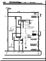
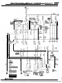
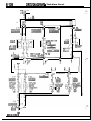
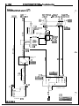
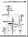
8-53
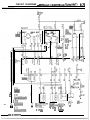
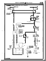
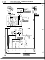
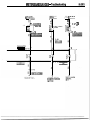
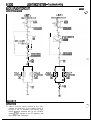
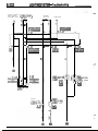
CIRCUIT DIAGRAMS - MPI Circuit <1.8L Engine-M/T>
SUB FUS IBLE
LINK
AIR CONDITIONER
CONTROL UNIT
3-BW
A-22
3C-12 lefel
i46i
COMBINATION
8%~:z~33PS
i3OPS 1)1)
N 8~~i
I1
ON+OFF:-
..2700 PB (384~8 I)
!I
N k!“;k% (2QQps I )
C-69
m
c
C-6;
MAGNETIC
CRLE i! EH
A-19X
-
C-65 64
C-64
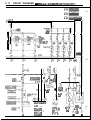
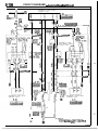
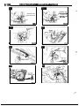
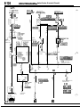
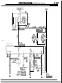
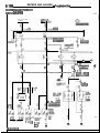
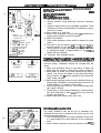
CIRCUIT DIAGRAMS - MPI Circuit 4.8L Engine-M/T>
8-54
r
102 C-64
py?jdJq
- - - - - - - - iv@ 1 f
17
r
F
3
--- ------- --- ___ _-----_-_---- -_----- __---------23 6
14 24 20
19
15
c+ %
3 3 ?
5
B
@
13
t
(VEHICLES FOR
CALIFORNIA)
B-08 m
KXa5-AC-UO514A-NC
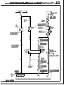
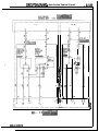
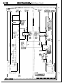
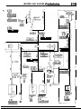
CIRCUIT DIAGRAMS - MPI Circuit 4.8L Engine-M/T>
,845
MPI
CONTROL
RELAY
7
-6
ial
INJECTOR
B-10
Iii@
c
1
-elm r
I
I
2
C-65
--------_$
MO:
.---- _--------------------
5
--____-__--_---------
r 18
---
T1
I
.---1
[ DR:
----.
58
12
-6
R:
3
12
2 A-47
3I-:
5
5
I
1
Y I
;
--I
L-LB-26
12
63
CONNECTOR
r
M
0
IDLE SPEED
CONTROL
ACTUATOR
CIRCUIT DIAGRAMS - MPI Circuit <1.8L Engine-A/T>
1.8L Engine <A/T>
IGNI’
SWITI
ION
I (ST)
3-BW
C-54
0
1OA
C
c-45
is
123
466
m
r
c-59
5
2
c:
J POWER
,TRANSISTOR
CRANK ANGLE
AND TOP DEAD
CENTER SENSOR
2 c-59
123
436
EB
--i
s
zi
Al
I
- -> - T
i13
m
f.G
Ii
-Z
]
:X35-AC-U0515-NC
d.4
C-64
I!i4
)
I
9
I
IGNITION
COIL
----_-.
I,21
s
14
1
I
I
I
II
I
C-69
10
cl
a
C-67
5
CIRCUIT DIAGRAMS - MPI Circuit <1.8L Engine-A/T>
JSIBLE
INHIBITOR
SWITCH
IGNITION
SWITCHtIGl)
:kKPUMP
1NNECTOR
r
7
MPI
CONTROL
RELAY
C-63 b
------------I
T
6
3
zI
::
-
3
/)FFon--5
%
s
cx
cu
c:
LX
.Y
C-64, 107
MPI
CONTROL
UNIT
n
0
UR35-AC-U0515A-NC
6 C-65
CIRCUIT DIAGRAMS - MPI Circuit <1.8L Engine-A/T>
8-58
SUB I
LINK
IBLE
AIR CONDITIONER
CONTROL UNIT
J/I
1
2
c-12 m
2422
@C
#&CATED
1OA
c
c
/
I)
ONiOFF :
210kPa~30Dsl)
!iw!h33,,
ON+OFF :
2700kPa (384~sl)
8%%% (2QQPS I )
7 C-67
!zI
it2
d
g4
,. C-58
G
'3 C-72
s
$:5 A-21 I e
3466
lEhfa
>
G
1
4-SPEED
AUTOMATIC
TRANSAXLE
biC.I$RDL
CIRCUIT DIAGRAMS - MPI Circuit ~1.8L Engine-A/T>
A-36
102 C-64
POWER
MOTOR
g;WtlT,iON
...
KX35-AC-U0515B-NC
Ii
B-03
lpqfQ@~
IDLE
SWITCH
GOURCE
I
I
THROTTLE
;;i;;EAF;fiiANT $E&&;ON
SENSOR
B-02
B-30
~~~
1
IBI
EGR
;;;;;;ATURE
(VEHICLES FOR
CALIFORNIA)
B-08 @@
CIRCUIT DIAGRAMS - MPI Circuit <1.8L Enaine-A/T>
8-60
7
g
6
I
1
PURGE
CONTROL
SOLENOID
VALVE
INJECTOR 1 INJECTOR 1 INJECT0
B-10
B-06
IEa
lm
I
2
C-65 31
52
-----_----- ------__--
5v
4
-23
I
IC
-
a
b
--1
3
C-67
16
---
v
-- --
59-l
8
3
1m
I
B-26
1e
CB
\/
J/B
I
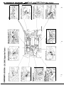
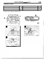
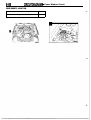
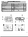
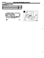
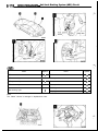
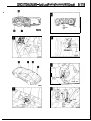
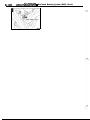
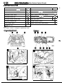
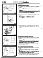
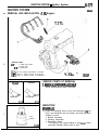
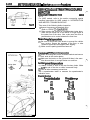
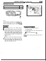
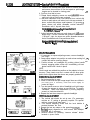
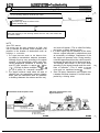
EOMPONENTS LOCATION < 1.8L ENGINE>
lanition timing adiustment
Ah-flow sensor
I_ntake tir, temperature sensor
terminal
EGR control solenoid. valve [Calif. only1
Purge
..
control .-. solenoid valve I --
1% . servo, IrIle posmon switC”, lvw3
--^
Crankshaft fa’gle sensor, -TDC sansor
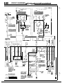
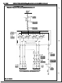
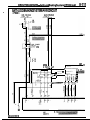
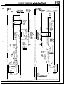
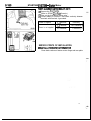
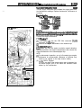
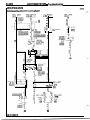
CIRCUIT DIAGRAMS - MPI
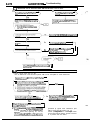
circuit ~2.0~ DOHC Engine (Non-Turbo)-M/T>
2.OL DOHC Engine (Non-Turbo) <M/T>
.---------_--------
2-BW a
2 E-47
pig
;b[bKPUMP
CONNECTOR
0
I
10
I
I
I
I
.-ON
4
B
i
ii
C-64 .07
3
iR
!C
t35-AC-lJ0515-NC
I
I
I
I
I
I
I
I
I
I
I
C-65156
E------------
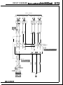
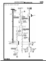
CIRCUIT DIAGRAMS
- MPI Circuit <2.OL DOHC Engine (Non-Turbo)-MIT>
a-63
IGNI [TI ?N
SW17TCH (IGl)
3-BW
7
J/B
1
!Ll
6
)1
NG NE SPEED
iCONNECTOR
DJE STMENT
14
r
c-05
"
rla~a~4~6lsl7la
lel
~0l11~1~15/14l16l15l1
~#hTOR '
B-15
3
C-6E 10
L -,L
I
3
3
r5
4
4,
7,
c
0
EC-67 13
c!0
+
COMBINATION
METERtTACHO)
El
-10- - - - - - - - - - - ,109
i
54
-------
d
34
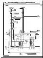
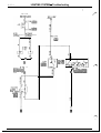
8-64
CIRCUIT DIAGRAMS
- MPI Circuit <2.OL DOHC Engine (Non-Turbo)-M/T>
_
Ix
1.25-R
4?
AIR FLOW SENSOR
I
INTIIS AIR AIR
TEYPERATURE
FLOW
BENBOR BENBOR
A-36
B-04
5
r
-6
Fsl
*
C-64 104 106 101 15
CK
I
m
I
93
Ki
%
ms
s
q3
cu
::
A EGR TEMPERATURE ENGINE
THROTTLE
= SENSOR
COOLANT
POSITION
FOR
;E;E;EATURE SENSOR
a (VEHICLES
CALIFORNIA)
B-02
rpJ&$l
B-30 i
Lid
KX35-AC-U0516A-NC
SWITCH
c
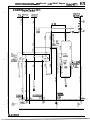
CIRCUIT DIAGRAMS - MPI
Circuit ~2.0~ DOHC Engine (Non-TurbobMfT>
II
II
II’
I
____--------------.- 4 l-6-J
2&
44
5
I
uo
SONNIES 1 or4
r
5
P
c-45 10mm4
pR?zEaq
I
c-54 5
J/B
12a4
5878 T
cu
m
F
-
B-26
REVERSE SIDE
-
8-66
CIRCUIT DIAGRAMS -
MPI Circuit <2,OL DOHC Engine (Non-Turbo)-M/T>
SUB FUSI
P
-i
U
,
‘5 C-72
A-19X
.,l
,\
,,5 A-21
2
1
3455
Ilfsf31
G"
,4l
94
IFI
ENGINE
~@#TuRE
2 B-31@
hlblYia~'C
4 C-67
7 C-66
C-6,
MPI
EFRoL
KXS-AC-U0516B-NC
Y
I
1
CIRCUIT DIAGRAMS - MPI circuit
&‘Ii”;t,,
~2.0~ DOHC Engine (Non-TurW-~>
2.OL DOHC Engine (Non-Turbo) <A/T>
TION
CH(ST)
IGN
SW1
PBLE -
F
--________________________ _____________
6
1~~
o
a
9
i?l
CL
4 E-47
fgal
C
E$IJbKPUMP
CONNECTOR
MPI
CONTROL
RELAY
C-63
2-BW
F
2 E-69
M
FUEL PUMP
1
INHIBITOR % B-25
SWITCH g
Al
0
G
"4
10
,\
F
_" 2
41
cu
=
ON
6
i
El
m
AJ
I
i
EL--------C3Li
MPI
CONTROL
UNIT
tX35-AC-U0517-NC
j6
104
C-64
__--__--__---~~---~~~~~
CIRCUIT DIAGRAMS - MPI
circuit ~2.0~
DOHC
Engine (Non-TurboIA/T>
3-BW
c-45
3
0
C
ADJUSTMENT
CONNECTOR
.O
:7
2
3
c!zP
3
lx
a-
3
r
1
m
t
COMBINATION
METERtTACHO:
C-67
i
c
II!
0
09
54
C-65 ;4
,------_ 55
-----_------------------------------%
CIRCUIT DIAGRAMS
- MPI Circuit <2.OL DOHC Engine (Non-Turbo)-A/l>
Y
2
AIR FLOW 6ENSOR
INTAKK
A-36
tic
-1
AIR
B-04
I 7
3
3
-6
al
al
i7
---
.C
iF
GND
GNI I
V
V
L
---
---_-
106 ~lolt%------------k@~20
1J
I
I
3
‘1
3
.--_
-- 58
E
----- ---rig
717
E
nI
k:
T- ;
1
‘=
h
6
KX35-AC-U0617A-NC
EGR TEMPERATURE g;gt;;iT
THROTTLE
;B;gfjEATURE @j&ON
B-02
B-08 @J
{m
.*OFF
7
IDLE
SWITCH
B-05
q
POWER
STEERING OIL
;['qB#RE
B-17b
>
8-70
CIRCUIT DIAGRAMS
- MPI Circuit <2.OL DOHC Engine (Non-Turbo)-A/T>
EGR
9
CONTROL
GOLENOID
h
VALVE
W;;ICLES
s
CALIFORNIA)
CONNECTION
m
a
GELFDIAGNOSIS
CHECK CONNECTOR
c-30
FRONT SIDE
piIzf#q
REVERSE SIDE
p!Ei&q
!
IGNITION OXYGEN
SENSOR
TIMING
ADJUSTMENT CHECK
CONNECTOR CONNECTOR
C-56
A-60
d
iz4
m
6
L-e9
OXYGEN
SENSOR
B-26
1 2
34
a3
E
4
CIRCUIT DIAGRAMS
1
SUB FUSII &J! LINK @
i
)
,C
:
1
8-73
- MPI Circuit <2.OL DOHC Engine (Non-Turbo)-A/T>
5CL
1
AIR
CONDITIONER
$&ROL
c-40
5
2
Y
S468
lEEa
!2 6
c
1-12
tz3
1-58
2
m
El,
1 c-47 .\l
x-
c-50 "2
G
1
E!s
C-67
XbFO&%“”
TRANSAXLE
CONTROL UNIT
\I
----_-------
-----------I
?4
I
KX35-AC-UOSl?d-MC
C-6L
8-72
CIRCUIT DIAGRAMS - MPI Circuit <2.OL DOHC Engine (Non-Turbo)>
CIRCUIT DIAGRAMS - MPI Circuit <2.OL DOHC Engine (Turbo)-M/T>
81;73
2.OL DOHC Engine (Turbo) <M/T>
MAIl
LIN:
IGNITIO:
ZWITCHt 1)
:
cl
{SIBLE
2-BW
8
c!
_________--_--_--_--------- -------3
2 5
i
P-RW
FUEL PUMF
AND GAUGE
AfSiiBLY
d0
Z-64
--
C-E
108
_-______________--_--------.
..
X3&AC-UOSlB-NC
8-74
CIRCUIT DIAGRAMS - MPI Circuit <2&L DOHC Engine (Turbo)-M/T>
3-BW
0
l3m c-54
r0
lQ84
6671
1 IOA
7
1
J/B
C% 3
IGNITION
COIL
B-14
z
12
3
E!l
TO SPARK
PLUG
14
RwE
ADJUSTMENT
CONNECTOR
7
2
I
z
z=
1
COMBINATION
METERtTACHO)
__--------------------
>
I
cP
9
C-67
=
54
C-65
_________-_--_-------~~-~~.
------- 55
109
%
ad-Q
‘O lo C/GigTpq
t
E2
i3 9
-c
CIRCUIT DIAGRAMS - MPI Circuit <2.OL DOHC Engine (Turbo)-M/T;
8-75
MPI
mBoL
CRANK ANGLE
AND TOP DEAD
CENTER SENSOR
A-36
m
1
2
s
cl
IA-32
I
1 A-51
0
>
-6
0
105
A
V
A
V
V
cl 3
LLcx>1
r
;
-67
cl
.-
h
0
KX35-AC-UOSlSA-NC
fXXS$fiMPERATURE
(VEHICLES FOR
CALIFORNIA)
B-08 @$J
it3
- - - I59
--
ENGINE
~~k%&iTURE
B-30 I
l!d
THROTTLE
;;~~&~oN
B-02
~~~
4
8-76
CIRCUIT DIAGRAMS - MPI Circuit <2.OL DOHC Engine (Turbo)-M/T>
nl. 25,-R
I
I
I
I
I
I
I
I
I
I
I
I
I
I
I
I
I
I
I
I
1
----- ------.g
- - - - - - - - - - 5 - - - - - - - - - - . ---I$
4
I
18
2
12
E
-
3
C-67
1. II
l ”,“j,
12
sk
12
El
IGNITION
TIMING
ADJUSTMENT
CONNECTOR >
I
A-60
$JQ
cz
4 %@!
.# CHECK
1
SELFDIAGNOSIS
CHECK CONNECTOR
c-30
FRONT SIDE
pi%iRTq
REVERSE SIDE
fiEFLiE]
CONNECTOR
C-56
;
El3
RING
K
SL, A”.‘
B-17 D
DETONATION
!f$#/
c?crr.znn
CXXKJ”K
-mI
I
Fl-3E
B-07
II&
CIRCUIT DIAGRAMS - MPI Circuit <2.OL DOHC Engine (Turbo)-M/T>
r
SUB FUSIE 3LE I LINK 6)
UNIT
--lc-40
‘FI
!?I
@’r 1
lOA’
1
2
\,
2’3
3
\I
c-5, S”1 2
5,2
piliJq
7r
J/B
@
iOA
I
0
A-OS
@P
“3
F
1
1
A-19X. j---
IC
OF;
t
r
KX35-AC-UO5i88-NC
C-64
03
i !z
1Y
65 C-65
ENGINE
F!%J~~~TATuRE
I SWITCH
8-77
8 - 7 8 CIRCUIT DIAGRAMS - MPI Circuit <2.OL DOHC Engine (Turbo)-A/T>
ZOL DOHC Engine (Turbo) <A/T>
IGNITION
SWITCHtST)
SUB FUSIBLE
LINK @
3-BW
J/B
c-59
5
r
WiEN
KEY IS
REMOVED
c!J
B-14
WITH
;fLHKZh
\
TO SPARK
PLUG
--
A-59 1
IBA
I - -
EsWE
ADJUSTMENT
CONNECTOR
.\6
/\
,,l
..8
/\
/\
==I-4
I
L
7
7
W
I
104
- - - - -C-64
------------
INHIhTOR
SW ITCH
B-25
2
Al
MPI
CONTROL
UNIT
K35-AC-UOSIQ-NC
ICOMBINATION
METER
(TACHO)
3
3
10
.--
2
3
m
I
% 1
4
IZ
54
- - - - - - 55 C-65
CIRCUIT DIAGRAMS - MPI Circuit <2.OL DOHC Engine (Turbo)-A/?>
<SIBLE
IGN
SWI'
8-79
ION
! (IGIl
c!
4
0
v..mKPUMP
CONNECTOR
, FWDI AAWD
-.
FUEL PUMP
AND GAUGE
ASSEMBILY
E-33
pzTiq
MPI
COVTROL
RELAY
C-63
.-------- k---
El
56
MPI
CONTROL
UNIT
KX35-AC-U051QA-NC
1 08 C-64
8-80
DIAGRAMS - MPI Circuit <2.0L DOHC Engine (Turbo):A/T>
CMXJIT
SUB FUS
51
3 LINK @
L
1
AIR
@@#ONER
UNIT
c-40
g
•a
B
J/B
1
c-l4i
DUAL
~~~I?~JRE
r
N-OFF:
8 10kPaEtODsl)
OFF-ON:
235kPa K%~DB I)
!#fll~~3.34PS I)
210OkPa (2ooDS I)
=4 C-58
Gt
y5 C-72
.4
ELC 4-SPEED
AUTOMATIC
TRANSAXLE
CONTROL UNIT
1 ENGINE
COOLANT
TEMPERATURE
inI SWITCH
Is
C-67+
9
--------------.
-t
C-65
C-64
03
A65 C-65
CIRCUIT DIAGRAMS - MPI Circuit <2.OL DOHC Engine (Turbo)-A/T>
849
MPI
CONTROL
RELAY
A-36
IPI
iKTRoL
_--__--
14
1.*
O FF
=
&TEMPERATURE
(VEHICLES FOR
CALIFORNIA)
KX35-AC-U051QEbNC
ENGINE
THROTTLE
COOLANT
;#lWBATURE &f&;~oN
B-30 m B-02
IDLE,
SWITCH
B-05
q,
--em------
11
ii2
, I.AWD,'
FWD
8-82
CIRCUIT DIAGRAMS - MPI Circuit <2.OL DOHC Engine (Turbo)-A/T>
C-6
lE3
RESISTOR I
r--J,?
0
A-58
2 A-13
I
,\ 1
2
/\
PURGE
CONTROL
SOLENOID
VALVE
FE8
\/
\I
_
1
I
A-14
”
-FUEL
PREWURE
vXlLf$OID
I88
A-15
1
IQI
2
\
-EGR
CONTROL
f’@O’D
'4
?
2
u WEWCLEG FOR
CALIFORNIA)
*/
\t
-
3'
+1
,l
\I
"5
?
z
?
zl
\I
6
%
7
4
ll
I3
c
lx I
t\ I
.
k
& B-106 B-096 B-066 B-Olm
m
.il
d\l
INJECTORYCT
I-_';;
Al
Al
.-.-----
E
1 02 C-61
-
- -----
-r
5
6-7
C-60
IGNITION
TIMING
ADJUSTMENT
CONNECTOR >
A-60
'
g
\/
D-05 2"
;;yh#NATION
ml2
SELFDIAGNOSIS
CHECK CONNECTOR
c-30
FRONT SIDE
fili%aq
REVERSE SIDE
pRi$q
POWER
STEERING
OIL
Hif#$RE
B-17 D
I
COMPONENTS LOCATION < 2.OL DOHC Engine (Turbo)>
Throttle position sensor
Ignition timing adjustment terminal
Fuel pump check terminal
EGR control solenoid valve [Calif. only]
Purge control solenoid valve
Fuel pressure control valve [Turbo only1
Injector
Ignition coil, Power transistor
ISC servo (stepper motor)
\LU
J/
Vaste gate control valve [Turbo only1
Plower steering fluid pressure switch
CIRCUIT DIAGRAMS - Cooling Circuit
35-AC-U0602-NC
CIRCUIT DIAGRAMS - Coolina Circuit
COMPONENTS LOCATION
N
a
m
Symbol
e
Name
Symbol
Air conditioner control unit
C
Condenser fan motor relay
B
Condenser fan motor High-Low select relay
B
Radiator fan motor relay
A
NOTE
The “Name” column is arranged in alphabetical order.
WA0734
Air condjtioner unit
MAO735
8-86
CIRCUIT DIAGRAMS - Power Window Circuit
POWER WINDOW CIRCUIT
SIBLE
3
IGNITION
SWITCH(IG2)
J/B
0
10A
5
15(A/T) C-67
'"lO(M/T) C-67
5
/t
3
POWER WINDOW
RELAY
X35-AC-U1107-NC
5
-,,4
/\ 1 A-05X
,
0-l
-
CIRCUIT DIAGRAMS - Power Window Circuit
POWER
WINDOW
RELAY
v
POWER
WINDOW
RELAY
Y
MAIN SWITCH
KYI
E-53 p&q
s*\5
(DRIVER'B RIDE)
I
ONE-TOUCH
DOWN
CIRCUIT
b
F
I
I
DOWN
:
-r-
!!ia%H
3
q OFF
4
i
@
--i-r-
\/
“1
+
ZJ
r(
,,
rl
I
+
3
)
I
I
I
11
7
3
.------
_------_--
I
1
I
J iAld
CL
I I I
E-64
c
C
6UB
SWITCH
(PASSENGER'S
SIDE)
E-05
2
1
3462
m
POWER WINDOW
MOTOR
E-54
POWER WINDOW
MOTOR
E-04
(PASSENGER'S SIDE)
CIRCUIT DIAGRAMS - Power Window Circuit
8-88
COMPONENTS LOCATION
Name
Power window relay
Symbol
A
CIRCUIT DIAGRAMS - ELC-4-Speed Automatic Transaxle Circuit
ELC-4-SPEED AUTOMATIC TRANSAXLE CIRCUIT
fy&F&SIBLE
IGNI ION
SWIl H(ST)
IGNI
SW11
2
cl
J/B
r
!ON
I (IGl)
7---_-~---_---- -__---____--____--__---------------@
IOA
-
.3
- - - l
- AWD
t
1
cl
i
Q
13 C-67
14 C-58
!3
i
e3
THEFT-ALARM
CONTROL UNIT
I
TERMINAL
I (LALTERNATOF
Q
,>
INHIBITOR
SWITCH
B-25
!
I
‘a
!
04 -1;
;-z!l I
!
!
3
4-SPEED
AUTOMATIt
;I??fpgL'
UNIT
STARTER MOTOR
:X35-AC-U0705-NC
03 I
4
L--
a
CIRCUIT DIAGRAMS - ELC-4-Speed Automatic Transaxle Circuit
8-90
[GHT
IGNITION
SWITCH(IG2)
m
+.I
1234
5278
_-------------$2 c-54 (EBEI/
P
o (LB)
2
\,
?I
,3
OVER
DRIVE
SWITCH
D-18
a. --.
0: N
\I
"4
F
\J
"5
3
POWER/
ECONOMY
"sHwT"H" OVER 'OKD-19
Ea
3458 1 2
3
?L-
I\
F
E
z
3
A/T SELECTOR
LEVER POSITION
ILLUMINATION
LIGHT
1
I
,I-
I
h
c-70
p@qGG%q
(1:
62
2
J,,609,!,g7g,,63
/\
/\
II
s
%
,,2
/\
m
94
" RHEOSTAT
3
1 6 C-45
J/B
r-L
-
Remark
,XMark i n d i c a t e s t h e optional wiring
;;;n7;s f o r auto-cruise c o n t r o l
.
CIRCUIT DIAGRAMS - ELC-dSpeed Automatic Transaxle Circuit
AIR CONDITIONER
CONTROL UNIT
IGNITION
COIL
R
51
-?- STOR
ONiOFF:
210RPe(30~sl)
OFFiON:
ONiOFF:
2700kPaC384Psl)
OFF+ON:
2100kPa(299PSl)
&
\1. 8L
/
ENGINE
6
4-SPEED
AUTOMATIC
;;FZK;;LE
UNIT
C-60
Y
Y
iJ
----.
06
SELF
-DIAGNOSIS
9 GNoD GNd) GsjD “tD
--a1
4
ml
CONNECTOR
c-30
FRONT SIDE
62
l-6
-01
0
- 19
AUTOCRUISE
CONTROL
UNIT
-6
0
\
v
/
B-24 4-SPEED AUTOMATIC
TRANSAXLE SOLENOID VALVE
KX35-AC-U0705A-NC
Remark
.XMark i n d i c a t e s t h e oPtlondl wirlnP
h a r n e s s f o r a u t o - c r u i s e c o n t r o l system.
8-92
CIRCUIT DIAGRAMS - ELC-6Speed Automatic Transaxle Circuit
r
1.8L ENGINE
2. OL DOHC ENGINE
: C-66
SUB FUSIBLE
LINK I 0
ts
Ill
lb1 1 c-47 B
l
5V
L-
n-3
Y 14
>
,C
19 fl3 f24
5
,
5
ON SFF
-Y
-_ _ - - - - - - - - p- - - d f
i--b---- 1 i_-_---
:ggg
ri
!
-4-@
-- -I
---1------
1
IDLE
SWITCH
B-05
q ’
-N+k
5-V
14
2
a
;
-I
1’ -,
’I
.--
gBg;;OWN
SWITCH
, A-38
.-
3
0c
L
Il-----ll
FRONT SIDE
CL
1.-- 3Y-- 4_-1
TURBO
1asaBoI
I-----I
I@
AUTOMATIC
;E#iAXLE
;Ei;;EATURE
;I
- - .-v. .
GENERATOR
11
6
SIDE
8-93
CIRCUIT DIAGRAMS - ELC-4-Speed Automatic Transaxle Circuit
:,.
COMPONENTS LOCATION
Name
1 Symbol 1
Symbol
Diagnosis connector
F
Pulse generator B
A
Engine control unit
I
Solenoid valves
C
Oil temperature sensor
D
Throttle position sensor
B
Power (PWR)/Economy (ECO) select switch
G
Transaxle control unit
H
Vehicle-speed sensor
E
Pulse generator A
NOTE
1. The “Name” column is arranged in alphabetical order.
2. Refer to GROUP 14-On vehicle inspection of MPI components for installation position of
sensor.
1.8L
Engine
2.OL DOHC
Engine
D
q
throttle position
8-94
CIRCUIT DIAGRAMS - ELC-4-Speed Automatic Transaxle Circuit
c, D i a g n o s i s \\
CIRCUIT DIAGRAMS - Central Door Locking Circuit
CENTRAL DOOR LOCKING CIRCUIT
Vehicles without theft-alarm system
SUB FU IBLE
LINK d
8
F.
I
I
15A
IOA
\I
1L
\/
I
\/
2,
I-F 10 c-51
1 c-50
.,2
\ ,,7
I\
UNLOCK
m
4 I
5
!3
I
I
E-63J.7
- 4 c-49
-t+
Y
12
cu
34
m
Al
DOOR LOCK
ACTUATOR
(LEFT SIDE)
E-49
1
0
KX35-AC-UllOB-NC
-E-09
DOOR LOCK
?8~8~~0~~DE, m
E-64
CIRCUIT DIAGRAMS - Central Door Locking Circuit
Vehicles with theft-alarm system
SUB FU IBLE
LINK 8
6
IGNITION
IGNITION
SWITCH(ACC) SWITCH(IG1)
!z
l.h 1 c-47 II!3
'
/\
8
15A
C-52
\/
------_
\/
1
o-\I
\/
\L
A,
\/
\I
1-F 10 c-53
1 c-50
,2 ,7
I\ ,\
m
5
!?I
EG-
CONTROL
z
IUNIT -____-%-----A=
I
;I-
iil;il.l:* “ffff
I-------- -______ V-Y
c-20
57 58
62 FiE!E9
- -----------------J
7 ll C-19
":
=J
mm
E-64
p7iE%Fq
H35-AC-UYlOg-NC
CIRCUIT DIAGRAMS - Central Door Locking Circuit
COMPONENTS LOCATIONS
-.
Symbol
Name
S
Door lock control unit
I Door lock relay
Theft-alarm control unit
I
A
I
B
Theft-alarm
control unit
8-97
CIRCUIT DIAGRAMS - Heater Circuit
8-98
HEATER CIRCUIT
SUB
LINK0
-_- FUSIBLE
~~~
-
“3
‘9
LW
IGNITION
SUB
EYWRl
LIGHTING
) SWITCH
%;FH
/\
J/B
0
z
,,l
/\
z
ch )
HEATER
CONTROL
\\L&h$lNATION
\I
',2
3-BW
_
!l
%
hi3
D-07
@zJ
1
2
I I 1; I I D-01
Illl.lnlall
c11
BLOWER
SWITCH
I
u(
I
m 4 c-49 ,2
34
El
CL
1
:X36-AC-U1207-NC
q
3627
/\ /\ I\ /\
L0.M
c -kJ”,” “,
I
w
0
/\
81199
CIRCUIT DIAGRAMS - Air Conditioner Circuit
AIR CONDITIONER CIRCUIT
SUB FUSIBLE LINKa
6UB
MK$jE
GNITION
)'.#H
-
s
l&l
SC
I 5dJ
%I7
7
In
In
5
' c-47/,3
,\
C
I!254
5878
m
c-54
--_----
J/B
BLOWER
RESISTOR
c-11
RHEOSTAT
D-01
J/B
X35-AC-Ul205-NC
El
kg
;I
d3 6 2 '7
" " " "
E
-77
CIRCUIT DIAGRAMS - Air Conditioner Circuit
8-100
SUB FUSIBLE LINK @
IGNITION
WH
MAIN FUSIBLE LINK@
9
3 A-52
.4
CONDENSER FAN
MOTOR RELAY
A-03X
___________---_-----_I
J
OFF- ON
12
3
A
54
El
5’”
&I..
1
5
A-22
_---_ _____ ------ ---- -
cl
s2
CONDENSER
0
RESISTOR
CONDENSER
( FAN MOTOR>
.A-32
i
0
GB
T-----l
@IATOR
ASSEMBLY
A-40
THERM0
SENSOR
ON-DOFF
: 78’ C (172’ F)
\,
$94
KX35-AC-Ul208A-NC
A-21
2
1
3452 [I
ll3a c
\'
OFF--ON
: 85’ C (185’ F)
5
-+
cu
-?
cu
_---
4
lA-22
.-I
5
CL t
CLtt
CONDENSER
FAN MOTOR
A-32
! A-21
1' e
1418
m
&TO1
CIRCUIT DIAGRAMS - Air Conditioner Circuit
i’s:
CONDENSER
SUB FUS BLE LINK 8
E#d8EoR
BLOWER SWITCH
0
7
P
aGW
II
c)
c-1of&gqq
6A-22
~!&DITIoNER
1 SWITCH
:
c
C
at
IPF
EC
--.
/C
0
EC
L
A/C
IND
I
e
i
P
CONTROL UNIT
2.OL DOHC
1. BL
ENGINE ENGINE
\
t
t2
34
ED
1
Q
3466
iafa
c-12
,
.--
Y
\
"2
7
2
El4
d ___-_---------~
,
zI
E
d
Ii
a
k
: 115' C (239' F)
t
OFF--ON
:
108’ C (226’ F)
I
-
:C-67
L
MPI CONTROL UNI'I
C-42a
8402
CIRCUIT DIAGRAMS - Air Conditioner Circuit
COMPONENTS LOCATION
Name
Name
Symbol
Symbol
Air conditioner control unit
D
Condenser fan motor relay
C
Air conditioner switch
G
Dual pressure switch
B
Air inlet sensor
F
Engine coolant temperature switch
<2.OL DOHC Engine>
A
Air therm0 sensor
F
Heater relay
H
Blower motor High relay
E
Magnet clutch relay
C
z;:enser fan motor High-Low selecting
C
NOTE
The “Name” column is arranged in alphabetical order.
-
-
CIRCUIT DIAGRAMS - Air Conditioner Circuit
16A0712
1
Heater relay -,i
84 03
8-104
CIRCUIT DIAGRAMS - Remote Controlled Mirror Circuit
~REMOTE CONTROLLED MIRROR CIRCUIT
IGNITION
WH
J/B
REMOTE
;;;;;;L'
SWITCH
I
I
(LEFT BIDE)
c
I
I
”
(RIGHT SIDE) I
REMOTE CONTROL MIRROR
tG
1
z
X35-AC-U1309-NC
CIRCUIT DIAGRAMS - Automatic Seat Belt Circuit
AUTOMATIC SEAT BELT CIRCUIT
IGN
SW1
ION
H (IGl)
EXJB FUSIBLE LINK a
3-BW
h
C-69
+%-,
i
COMBINATION
METER
;JC-27
13
J.12
AUTOMATIC
SEAT BELT
CONTROL UNIT
E-41
7
0
ji7EBiq
E-06 l--OUTER
SWITCH
OFF * ON
---.
2
(%ki
1
K35-AC-UlSlP-NC
'
8406
CIRCUIT DIAGRAMS - Automatic Seat Belt Circuit
AUTOMATIC SEAT BELT
CONTROL UNIT
SUB FUSIBLE LINK Q
I
E-41
5
lEEBl
a50
123 c-7P 'I 4
7
cu
j
I
If3 2
c- 16
5 "16
E
-,,S-__--__-____--------C-17*
------ -----1
IT7
5
L
E
CL
I*2 E-65
i2-_---------- ----- _-e--_--e----,.
2
E-46
____------.
5
1
FE%
(LEFT
SIDE) c
OF?
AUTOMATIC SEAT
BELT MOTOR RELAY
(RIGHT SIDE)
3
E
\/ \/
I
;’ ;‘m[
55 !z
---- 3- _-------- -5
5
1
s
E-57
3
c- 3,c
-.-
ii
------ I
I
I
.-v-w--
AUTOMATIC SEAT BELT
CONTROL UNIT
E-41
SIDE) AUTOMATIC SEAT BELT
CONTROL UNIT
m
7
c-51
J/B
C-54 5
43
@.I
===t
,234
c
C
667E
m
q
II
I I
1
11213
41612
7~11~~~10~11~1~1~1
II
g- R e m a r k
-The gonnectqr.indicated,bY
t n e x sYmt3oL Is appllcaole To
v e h i c l e s w i t h ABS.
J
CIRCUIT DIAGRAMS - Automatic Seat Belt Circuit
COMPONENTS LOCATION
Name
I
c
Name
Symbol
1 Symbol
Automatic seat belt control unit
C
Fasten switch
A
Automatic seat belt motor
E
Key reminder switch
I
Automatic seat belt motor relay
D
Outer switch
F
Buckle siitch
G
Seat belt warning light
J
Buzzer
K
Release switch
H
Door latch switch
B
-
-
8-108
CIRCUIT DIAGRAMS - Automatic Seat Belt Circuit
Automatic seat
Automatic seat
belt control unit
Automatic seat
16A0745
Oyer switch
I
19A0340
Kev reminder switch
CIRCUIT DIAGRAMS - Buzzer Circuit
w---ZZER CIRCUIT
- -- (VEHICLES FOR CANADA)
IGNITION SWITCHtIGl)
z
j234
5875 C-54 L-h7
m
,\
SUB FUSIBLE LINK @
s
"J c-47 I!3
'
/\
22
3
I /k
0
/
WHEN KEY
IS REMOVED
g
,\1\ c-05
,I
KEY .'
c!J
WHEN KEY
IS INSTALLED
1 r----+14 C-69
SEAT BELT
%MG
COMBINAl
METER
I
WITH
EKaSTEM
DIODE
E-52
F
c-37x
34
l33l
B
BfiaRBELT
J/B
,.
ATl
5 c-54
1234
58711
m
lEEa
-AC-U1519-NC
1
2 E-48
FRONT DiOR SWITCH
(LEFT BIDE)
8-110
CIRCUIT DIAGRAMS - Buzzer Circuit
COMPONENTS LOCATION
Name
Seat belt timer
Symbol
A
CIRCUIT DIAGRAMS - Anti-Lock Braking System (ABS) Circuit
ANTI-LOCK BRAKING SYSTEM (ABS) CIRCUIT
..
<FWD>
;USIBLE
4
1
1
DIODE
E-13
GR @
@EJ
A-34 jl_-
-
r
HYDRAULIC
52
0 UNIT
,L-------------l
1; A-35
I
- VALVE IL SOLENOID
VALVE
RELAY
I
\\
,,
I
I
XarrM I
, .I 4' I
____---------3
-T-3--5- %-->
E-12
(X35-AC-U1513-NC
8-112
CIRCUIT DIAGRAMS - Anti-Lock Braking System (ABS) Cihit
STOP
LIGHT
SWITCH
c-02
d
i
STOP LIGHT
c
c-17 11
-1
c
25
CIRCUIT DIAGRAMS - Anti-Lock Braking Svstem (ABS) Circuit
SPEED SENSOR
A
r
FRONT
(LEFT SIDE) (RIGHT SIDE)
A-23
A-54
@
@j
\
REAR
(LEFT SIDE) (RIGHT SIDE)
A-39
A-37
Ltfa
ml
u7J-L
T
I
1
1
2
3456
m
c-73
7J-LJ-L
1
2
2
r.9
A
3
3.I
5
TIT
?
F
10 11 A28
-
J.
II
J.
GND
V
G'Nl D
V
GND
V
24
.:
1,
18 C-17,
10
1
;~i&DIAGNOSIS
CONNECTOR
C-30 FRONT SIDE
p!&dzFq
REVERSE SIDE
pTq%$q
KX35-AC-UlSWA-NC
ABS
CONTROL
UNIT
P
U
I
8413
8-114
CIRCUIT DIAGRAMS - Anti-Lock Braking System (ABS) Cilicuit
<AWD>
MAIN &hSIBLE
LINK FI-
EY’KFUS I BLE
@
I
!z
Lk
J/B
c-47 I!3
y
@
&
A
10A
-
E
L_I
(LR) o
(LR)
2 c-17
M
E
I
-.
IN
i
I
1
DIODE
E- 13
@%J
52
A-34 51
--I
I
G SENSOR
E-36
3.-------------,
UNIT
------j 1 A-35
SOLENOID
VALVE
xlx$
1G
--
\
e
ck
-
18
,2
-A?2 fi35
/,5 ,,26 ,,27
y
cu
,17
I?+
-II
ii
ABS
$#X);ROL
I(:X35-AC-U1514-NC
E-12
[
II
iI
I
I
I
I
I
------I
7 -x--5
al&I al
GR @
HYDRAULIC
CIRCUIT DIAGRAMS - Anti-Lock Braking System (ABS) Circuit
8315
gJg c-o3 7$35
1
1
\
“14 c-17
1
0.05-G
11
STOP LIGHT
c
c
29
1
m
..
“p
N
i
ii
I
RESISTOR
E-14
8416
CIRCUIT DIAGRAMS - Anti-Lock Braking System (ABS) Circuit
SPEED SENSOR
FRONT
(LEFT SIDE) (RIGHT SIDE)
A-23
A-54
ULJ-L -LrLrL
1
i
R
REAR
*
(LEFT SIDE) (RIGHT SIDE)
E-39
E-37
I$&
m
5--
2
‘r
?
rT
A
A
r
33
-
10
-
28 30
-
iG
-
GG
-
zi
-
GND
V
I
I
I
I
I
L.
;;WiDIAGNOSIS
CONNECTOR
C-30 FRONT SIDE
-1
REVERSE SIDE
piT%$q
KX35-AC-U1514A-NC
0
c
3
2
?-I
GND
V
ABS
CONTROL
UNIT
E-12
CIRCUIT DIAGRAMS - Anti-Lock Braking System (ABS) Circuit
847
COMPONENTS LOCATION
<FWD>
Name
Name
Symbol
Symbol
F
ABS control unit
F
Diode
ABS motor relay
A
Front speed sensor
ABS power relay
F
Rear speed sensor
G
ABS valve relay
A
Self-diagnosis connector
D
ABS warning light
B
Stop light switch
C
E
NOTE
The “Name” column is arranged in alphabetical order.
warning
light
8-118
CIRCUIT DIAGRAMS - Anti-Lock Braking System (ABS) Circuit
<AWD>
Symbol
Name
Symbol
Name
G
G
Diode
A
Front speed sensor
ABS power relay
G
G-sensor
F
ABS valve relay
A
Rear speed sensor
H
Self-diagnosis connector
D
Stop light switch
C
ABS control unit
ABS motor relay
ABS
warning light
I
I
E
B
NOTE
The “Name” column is arranged in alphabetical order.
CIRCUIT DIAGRAMS - Anti-Lock Braking System (ABS) Circuit
-
light
16AO734
connector
8-713
8-120
CIRCUIT DIAGRAMS - Anti-Lock Braking System (ABS) Circuit
8421
CIRCUIT DIAGRAMS - Auto-Cruise Control Cikuit
AUTO-CRUISE CONTROL CIRCUIT
<M/T>
IGNITION
SWITCHtlGl)
I
J/B
-.
i--i”-I
9.
GND
V
”
V
14
m
m
\: 7 C-67
[j-j
22
P+
5v
?
GND
24
63
5.5
x
$-+ /
3
SELF-DIAGNOSIS
CONNECTOR
C-BOFRONT SIDE
wi!Fq
REVERSE SIDI
pig&q
m
a:
m
GND
m
m
0
c-55
J/B r
m
A
,
n
Ii
X35-AC-Ul515-NC
I In c-m
5 c-54
2-B'?
AUTO-CRUISE
CONTROL UNIT
c-01
CIRCUIT DIAGRAMS - Auto-Cruise Control Circuit
8-122
IGNIT 3N
SWITC (1Gl)
1234
667.3
IEEl
AUTO-CRUISE
"Co;TROL UNIT
7 c-54
SUB
LINI(
!
I
J/B
SIBLE
Eli
1 c-47
q
1
1
I
'3 C-52
6 c-55
20 -
COLUMN SWITCH
AUTO-CRUISE
CONTROL SWITCH>
C-06
.-I
\I
I
0.85-GW1
0. a5-GW
y4
STOP
L I G H T '------0
SW1TCH
c-03 OFFl%
a$1
?"3
O
2
OPEN
CONNECTOR
0
.-I
0
I
I
I
I
I
I
I
I
I
I
I
I
I
I
I
J/B
c-02
3
c
AUTOCRUISE
CONTROL
VACUUM
PUMP
A-11
I
C
I c
;)
-
6
E-
AUTO-CRUISE c-01
CONTROL UNIT
,
CIRCUIT DIAGRAMS - Auto-Cruise Control Circuit
3:12&
dl
1
lx+- ON
-
-.
I
I
I
I
I
I
I
I
I8
‘I !E
!
-L
I
Di
cl
.9
4
23
8
- __p_p---
MPI
C-66
CONTROL
UNIT
KX35-AC-Ul515A-NC
1I I
L
I
CIRCUIT DIAGRAMS - Auto-Cruise Control Circuit
8-124
<A/T>
SUE
LIR 2f!E
:
I:
IGNIl
SWIT[
a
1
El
IN
IGNITION
SWITCH(IG2)
ST)
-7
IGNITION
SWITCHtIGl)
?I m
4
25
1234
@J 2-----______----~-----~
C-54 loT1
h7
1 c-47
J/B
--I
03 1 J/B
log
10A I,
\I
4 C-52
c!3
~=TiqFmq
'13 c-50
"6
C-45
fii!asq
c
3
z
OVER
DRIVE
SWITCH
WHEN
KEY IS
REMOVED
c!z
&I
%
-c-J
/I3
FF
D- 18
ON---'
1
2
3466
m
3
I
* \I
+'4 "5
OD OFF
INDICATOR
LIGHT
3
23
GND
3
AUTO-CRUISE
CONTROL UNIT
v
!2
SELF-DIAGNOSIS
CONNECTOR
c-30
FRONT SIDE
pi!i&mq
REVERSE SIDE
p-!RGq
C-67
THEFT-ALARM
CONTROL UNIT
(36-AC-UlS¶B-NC
STARTER
MOTOR
m
cl
1
-
ta
EEl
CIRCUIT DIAGRAMS - Auto-Cruise Control Circuit
.
IGNITION
SWITCHtlGl)
I
SIBLE
6 C-55
COLUMN SWITCH
CONTROL SWITCH>
C-06
.-I
I,
9
0.65-GW-
0.85-GW
0.85-G
r-~-----------d *6 c-58
II
II
2
I
11
P
?
z
STOP
LIGHT
16
AUTO-CRUISE c-01
CONTROL UNIT
8-126
~
CIRCUIT DIAGRAMS - Auto-Cruise Control Circuit
4-SPEED
l$Tpml~~
CONTROL
UNIT
5V
9
4
I
19
n
q
c-55
J/B
a
c:
n
KXJ5-AC-Ul516A-NC
10
1
m
6.
c-45
i C-54
CIRCUIT DIAGRAMS - Auto-Cruise Control Circuit
AUTO-CRUISE
CONTROL-UNIT
Y5
c-01
I
5
$It
16 C-67
-------
t
3-02
zfz-fzg
2
4
r----l-
VL
J
3
1
r
IDLE
1 SWITCH
B-05
El
c
MPI
C-66
CONTROL
UNIT
II
CIRCUIT DIAGRAMS - Auto-Cruise Control Circuit
COMPONENTS LOCATION
Name
Name
Symbol
1 Symbol 1
Accelerator pedal switch <AIT>
K
Idle switch
Auto-cruise control actuator
C
Inhibitor switch <A/T>
I
A
I
Auto-cruise control switch
H
Motor position sensor (Idle switch)
I
D
I
Auto-cruise control unit
E
Overdrive switch <A/T>
1
J
1
Auto-cruise control vacuum pump
B
Stop light switch
I
L
I
Auto-cruise indicator light
F
Throttle position sensor
I
D
I
Clutch switch <M/T>
M
Vehicle speed sensor (Reed switch)
I
G
I
4 A/T control unit
I
NOTE
The “Name” column is arranged in alphabetical order.
<Engine compartment>
<Interior>
v
77
<1.8L engine>
osition sensor
Auto-cruise control
Auto-cruise indicator light
I
Vehicle speed sensor
(Reed switch)
1eAo728
CIRCUIT DIAGRAMS - Theft-Alarm Circuit
THEFT-ALARM CIRCUIT
Vehicles without daytime running light
lx
;;l;;IGHT
,,3
",,4
I\
-------------
A-02X
lxt
9 C-72
52 C-20
HEAIlbkFQT
SIDE)
A-28
Q@./
! E-48
J/B
c-54 “
:35-AC-U1517-NC
5
VEI?
3E)
(PA!y;;iR
,
DOOR SWITCH
CIRCUIT DIAGRAMS - Theft-Alarm Circuit
SUB FUSIBLE
LINK a
I\l
69
J/B
0
10A
10A
\L
C-51
i-2
\I
\,
30
2 7
+ ‘p
DOOR
LOCK
RELAY
c-34x
p&q
\,
\I
c-45 m 11
c-50 a ]
!2
\I
l
g4
g 61
- -_
V
V
I
I
I
V
t
4-s
E-50
i-i&l
m
i
I
r-L 7-J
c-51
m
t7
i
Irn ,,
Ire
7
L-+2
m
I
8-132
CIRCUIT DIAGRAMS - Theft-Alarm Circuit
J/B
12
24
I Ei
c-49
c
,8
1.25-G
C-72
•J
ii
:
f%F
CONN
C-
KX35-AC-UlSl?A-NC
iGNOS I S
'OR
P
%
;I
Y
E
A-30 s 1
A-45 .i
A-29
c
A-44 7
cp“1
q :
ri
c-19
1.25-G
k&B
SWITCH
HOOD
SWITCH
A-50
ml
IgK
CIRCUIT DIAGRAMS - Theft-Alarm Circuit
r
.c
(M/T)
I
:RY
IGNI-I 3N
SWITC
(ST)
#;I lDER
SWIi jH
(A/T) KE
RE I ER
SW\ JR
IGNITION
SWITCH(ST) 1
G
ch
---r
lEBl
1 2
24
B-27
P
---
q
B-2'
1
=
=
STARTER MOTER
ZZ
=
STARTER MOTER
CIRCUIT DIAGRAMS - Theft-Alarm Circuit
Vehicles with daytime running light
SUB F SIBLE
LINK &
-T-
,
%
C-72
a
::12
%
,,3 ,p
I\ /\
C-20
r56____-_-----__---_--C-46
COLUMN
SWITCH
c-07
r
I
I
I
I
L
JIMMER
----Ev
Kl
A
(35-AC-U1518-NC
PASSING
--_-__
“6
m
C-L
CIRCUIT DIAGRAMS - Theft-Alarm Circuit
IGNI'I
IGNITION
J,T- --__ - _____________ Ti
‘-
w
0
5
DIODE x 1~
a c-33
%
c!J l
k
5L-- ----_
-.
r
1
---------------------------,
111
I
Ii
i
--------------- -------
i5
I
I
--__-----___----__--------1
i
E 66
%I
@J
E-48
f
OFF'
(DRIVER 8IDE)
(PASSENGER SIDE)J
L
7
DOOR SWITCH
CIRCUIT DIAGRAMS - Theft-Alarm Circuit
8-136
6UB FUSIBLE
LINKa
J/B
@
@
15A
-1
\I
\I
\I
10A
-I
\/
I
iRELAY
.%oc~
4 C-52
c-50,
P
g;X);flNATION
D-06
c-34x
m]
mi
1
cwlgm~q-;~5__--__________-____
%iI%t"B"N?T $
w/
n
5v
n
,' '-"
T ---------.--.-------
F
12
V
V
P+
u0
P
v____---v----------------------c
E-58
DOOR LOCK
fXXU$$~R
SIDE)
E-49
C-54 cd'5
KXIS-AC-UlSlBA-NC
CL
CIRCUIT DIAGRAMS - Theft-Alarm Circuit
1
EG-
J/B
HORN
RELAY
C-36
1
c-49
1.25-G
,,8 1.25-G
,I
cI
c-72
::
c
A-30 .i 1
li!F&
SIDE)
A-29
la
c-19
THEFT-ALARM
CONTROL UNIT ----. IO m]
'I--------------
F
$1
k
s
A-45 c
A-44 c
l!a :!
c
CIRCUIT DIAGRAMS - Theft-Alarm Circuit
8-138
r,
_-_------ -_- ---- -------------I
(M/T)
NDER
'CH
IGNI'I
SWIT(
a
I
SWITCHGTIFJ rERYI
IGNITION
2&I
.rOFF
IN
3
I
LwTER
c-35x
1 e
34
EBI
0
I
I
I
I
I
I
I
I
zl I
CL
i 1m
El
I ri.!l.0i
AUTOCRUISE
t/(l;ROL
3
1
IN
OFF:
‘I
INHIBITOR
SWITCH
%I B-25
z
CL ,
mlzi
I
$
A-10 6.Q - - - CU,,~
ii
Al
I
STARTER MOTER
L_p_-_-_..-.--_-_-_
KX35-AC-U1518B-NC
ii
C-L
0
STARTER MOTER
_---_---_-_~ I
CIRCUIT DIAGRAMS - Theft-Alarm Circuit
8439
COMPONENTS LOCATION
-.
Name
Symbol
Theft-alarm control unit
I Theft-alarm
horn relay
I
Name
A
Theft-alarm starter relay <A/T>
D
Theft-alarm starter relay <M/l>
control
unit
16AO734
Symbol
C
I
B
I
8444
..
:
I
I
ENGINE
ELECTRICAL
CONTENTS
\
CHARGING SYSTEM ....................................
Alternator ....................................................
Service Adjustment Procedures .................
Charging System Inspection ..................
Specifications ..............................................
General Specifications ............................
Service Specifications .............................
Torque Specifications .............................
Troubleshooting ...........................................
IGNITION SYSTEM .......................................
Distributor ...................................................
Ignition System ...........................................
Service Adjustment Procedures .................
Ignition Timing Adjustment
For 1.8L Engine ......................................
Ignition Timing Adjustment
For 2.OL DOHC Engine ..........................
142
148
144
144
142
142
142
142
143
169
183
177
173
173
174
Spark Plug Cable Test ............................
Spark Plug Test ......................................
Specifications ..............................................
General Specifications ............................
Service Specifications .............................
Torque Specifications .............................
Troubleshooting ...........................................
STARTING SYSTEM .....................................
Starter Motor ..............................................
Specifications ..............................................
General .Specifications ............................
Service Specifications .............................
Torque Specifications .............................
Troubleshooting ...........................................
NOMA-
175
?76
169
169
170
170
171
153
157
153 :m
153.
153
154
154
CHARGING SYSTEM - Specifications
CHARGING SYSTEM
SPECIFICATIONS
GENERAL SPECIFICATIONS
NOBEB-
Specifications
Items
Alternator
Type
VIA
Rated output
<U.S.A. - M/T - Non-Turbo>
<U.S.A. - AA, U.S.A. - Turbo, CANADA - 1.8L Engine,
CANADA - 2.OL Engine - M/T - Non-Turbo>
<CANADA - 2.OL Engine - A/T, CANADA - 2.OL
Engine-Turbo>
Voltage regulator
Alternative current type with voltage regulator
1 Z/65
12175
12190
Electronic built-in type
SERVICE SPECIFICATIONS
Specifications
Items
Alternator
Standard value
Regulated voltage V
14.2-15.4 at -2OOC
1 3 . 9 - 1 4 . 9 a t 20°C
1 3 . 4 - 1 4 . 6 a t 60°C
13.1-14.5 a t 80°C
22.7 l.894)
3-5
Slip ring O.D.
mm (in.)
Rotor coil resistance
Q
Limit
Output current A
Slip ring O.D.
mm (in.)
65 A
75 A
90 A
Min.
Min.
Min.
22.1
(-4OF)
(68OF)
(14OOF)
(176°F)
45.5
52.5
63
l.870)
TORQUE SPECIFICATIONS
Items
Nm
ftlbs.
Lock bolt
Alternator brace mounting bolt
Adjust bolt
Alternator pivot nut
Water pump pulley bolt
Alternator wiring harness connector mounting nut
12-15
15-22
8-12
20-25
8-10
4-6
9-11
II-16
6-9
15-18
6-7
3-4
CHARGING SYSTEM - Troubleshooting
TROUBLESHOOTING
- H A L
CIRCUIT DIAGRAM
IGNITION
%TF
I
VEHICLES
FOR
U. 8. A.
-,
t
&
COMBINATION
OPERATION
When engine is stopped
When the ignition switch is switched to the “CN”
position, electricity flows from the “L” terminal, of the
alternator to the field coil, and at the same time the
charging warning light illuminates.
When engine is being started/has started”
When the engine is started, charging voltage is
applied to the “L” terminal of the alternator, with the
result that the charging warning light is extinguished.
In addition, because battery voltage is applied to the
“S” terminal of the alternator, this battery voltage is
monitored at the IC voltage regulator, thus switching
ON and OFF the current to the field coil and thereby
controlling the amount of generation by the
alternator.
Power is supplied to each load from the “6” terminal
of the alternator.
NOTE
The alternator relay functions as a back-up for the
flow of electricity to the field coil if there is a
disconnection or damaged wiring of the charging
warning light.
f
L
____ 2 S-l9@iJ
TROUBLESHOOTING HINTS
1. Charging indicator light does not go on when the
ignition switch is turned to “ON”, before the
engine starts.
l Check the bulb
2. Charging indicator light fails to go off once the
engine starts.
0 Check the IC voltage regulator (located within
the alternator).
3. Discharged or overcharged battery.
0 Check the IC voltage regulator (located within
the alternator).
4. The charging warning light illuminates dimly.
0 Check the diode (within the combination
ALTERNATOR
F-r
COMPONENT LOCATION
meter) for a short-circuit.
Name
Alternator relay
El---
Symbol
A
8-144
CHARGING SYSTEM - Service Adjustment Procedures
SERVICE ADJUSTMENT PROCEDURES
CHARGING SYSTEM INSPECTION
NOBEIAO
VOLTAGE DROP TEST OF ALTERNATOR OUTPUT WIRE
This test judges whether or not the wiring (including
the fusible link) between the alternator B terminal and
the battery ( + 1 terminal is sound by the voltage drop
method.
Preparation
(1) Turn the ignition switch to “OFF”.
(2) Disconnect the battery ground cable.
13) Disconnect the alternator output lead from the
alternator “B” terminal.
(4) Connect a DC ammeter (0 to lOOA) in series to
the “B” terminal and the disconnected output
lead. Connect the ( + 1 lead of the ammeter to the
“B” t e r m i n a l a n d t h e (-1 lead to the
disconnected output wire.
Voltmeter
Test
(1) Start the engine.
(2) Turn on or off the headlights and small lights and
adjust the engine speed so that the ammeter
reads 20 A and read off the voltmeter indication
under this condition.
Result
(1) It is okay if the voltmeter indicates the standard
value.
Standard value: 0.2 V max.
(2) If the voltmeter indicates a value that is larger
than the standard value, poor wiring is
suspected, in which case check the wiring from
the alternator “B” terminal to fusible link to
battery ( + 1 terminal. Check for loose connection,
color change due to overheated harness, etc. and
correct them before testing again.
NOTE
Use of a clamp type ammeter that can measure
current without disconnecting the harness’ is
preferred. The reason is that when checking a
vehicle that has a low output current due to poor
connection of the alternator “B” terminal, such
poor connection is corrected as the “B” terminal
is loosened and a test ammeter is connected in
its place and as a result, causes for the trouble
may not be determined.
(5) Connect a digital voltmeter between the
alternator “B” terminal and battery (+ 1 terminal.
Connect the ( + ) lead wire of the voltmeter to the
“B” terminal and the ( - 1 lead wire to the battery
( + 1 terminal.
(6) Connect the battery ground cable.
(7) Leave the hood open.
Ammeter
(3) Upon completion of the test, set the engine speed
at idle.
Turn off the lights and turn off the ignition switch.
(4) Disconnect the battery ground cable.
(5) Disconnect the ammeter and voltmeter that have
been connected for the test purpose.
(6) Connect the alternator output wire to the
alternator “B” terminal.
(7) Connect the battery ground cable.
8445
CHARGING SYSTEM - Service Adjustment Procedures
OUTPUT CURRENT TEST
This test judges whether or not the alternator gives
an output current that is equivalent to the nominal
output.
Preparation
(I 1 Prior to the test, check the following items and
correct as necessary.
(a) Check the battery installed in the vehicle to
ensure that it is in sound state*. The battery
checking method is described in “BATTERY”.
NOTE
“The battery that is used to test the output
current should be one that has been rather
discharged. With a fully charged battery, the
test may not be conducted correctly due to
an insufficient load.
(b) Check tension of the alternator drive belt. The
belt tension check method is described in
“GROUP O-Maintenance Service”.
--A
I
(2) Turn off the ignition switch.
(3) Disconnect the battery ground cable.
(4) Disconnect the alternator output wire from the
alternator “B” terminal.
(5) Connect a DC ammeter (0 to lOOA) in series
between the “B” terminal and the disconnected
output wire. Connect the (+ 1 lead“ of’ the
ammeter to the “B” terminal and connect the
I- 1 lead wire to the disconnected output wire.
NOTE
Tighten each connection by bolt and nut securely
as a heavy current will flow. Do not relay on clips.
(6) Connect a voltmeter (0 to 2OV) between the “B”
terminal and ground. Connect the ( f 1 lead wire
to the alternator “B” terminal and (-1 lead wire
to a sound ground.
(7) Set the engine tachometer and connect the
battery ground cable.
(8) Leave the engine hood open.
80A or IOOA
indf%toi
~
Ignition
switch
Alternator relav
Test
(1) Check to see that the voltmeter reads the same
value as the battery voltage.
If the voltmeter reads OV, an open circuit in the
wire between the alternator “B” terminal and
battery ( - ) terminal, a blown fusible link or poor
grounding is suspected.
(2) Turn on the headlight switch and start the engine.
Voltmeter
Ammeter
16PO482
(3) Set the headlight at high beam and the heater
blower switch at HIGH, quickly increase the
engine speed to 2,500 rpm and read the
maximum output current value indicated by the
ammeter.
NOTE
After the engine start up, the charging current
quickly drops, therefore, above operation must be
done quickly to read maximum current value
correctly.
8-146
CHARGING SYSTEM - Service Adjustment Procedures
Result
(I 1 The ammeter reading must be higher than the
limit value. If it is lower but the alternator output
wire is normal, remove the alternator from the
vehicle and check it.
Limit value:
45.5A min . . . . . . . . . . . . . . . . . . . . . . . . . . . . . . . . . . . 65A
52.5A min . . . . . . . . . . . . . . . . . . ..*.............. 75A
63A min . . . . . . . . . . . . . . . . . . . . . . . . . . . . . . . . . ..a
90A
Caution
(a) The nominal output current value is shown
on the nameplate affixed to the alternator
body.
(b) The output current value changes with the
electrical load and the temperature of the
alternator itself.
Therefore, the nominal output current
may not be obtained if the vehicle electrical load at the time of test is small.
REGULATED VOLTAGE TEST
The purpose of this test is to check that the electronic
voltage regulator controls the voltage correctly.
Preparation
(I) Prior to the test, check the following items and
correct if necessary.
(a) Check the battery installed on the vehicle to
see that it is fully charged. For battery
checking method, see “BATTERY”.
(b) Check the alternator drive belt tension. For
belt tension check, see “GROUP OMaintenance Service”.
(2)
(3)
(4)
(5)
(6)
In such a case, keep the headlights on to
cause discharge of the battery or use lights
of another vehicle as a load to increase the
electrical load. The nominal output current
may not be obtained if the temperature of
the alternator itself or ambient temperature
is too high. In such a case, reduce the
temperature before testing again.
Upon completion of the output current test, lower
the engine speed to the idle speed and turn off
the ignition switch.
Disconnect the battery ground cable.
Remove the test ammeter and voltmeter and the
engine tachometer.
Connect the alternator output wire to the
alternator “B” terminal.
Connect the battery ground cable.
(2) Turn the ignition switch to “OFF”.
(3) Disconnect the battery ground cable.
(4) Connect a digital voltmeter between the “S”
terminal of the alternator and ground. Connect
the ( + 1 lead of the voltmeter to the “S” terminal
of the alternator, inserting from the wire side of
the 2-way connector and connect the ( - ) lead to
sound ground or battery I- 1 terminal.
- Load
Voltmeter
(5) Disconnect the alternator output wire from the
alternator “B” terminal.
(6) Connect a DC ammeter (0 to lOOA) in series
between the “B” terminal and the disconnected
output wire. Connect the (+ 1 lead of the
ammeter to the “B” terminal and connect the
(- 1 lead wire to the disconnected output wire.
(7) Set the engine tachometer and connect the
battery ground cable.
Ammeter
Test
(1) Turn on the ignition switch and check that the
voltmeter indicates the following value.
Voltage: Battery voltage
If it reads OV, there ils an open circuit in the wire
between’ the alternator “S” terminal and the
battery (+I or the fusible link IS blOWn.
(2) Start the engine. Kebp all lights and accessories ‘,Off.
(3) Run the engine at a’ speed of about 2,500 rpm
and read the voltmeter when the alternator output
current drops to 1Ok or less.
8-147
CHARGING SYSTEM - Service Adjustment Procedures
Result
I’) $
(1) If the voltmeter reading agrees with the value listed in’ the
regulating voltage table below, the voltage regulator is
functioning correctly. If the reading is other than the standard
value, the voltage regulator or the alternator is faulti/., ,
Regulating voltage table
Voltage regulator ambient
temperature OC (OFI
Regulating voltage-V
- 2 0 (-4)
20 (68)
60 (140)
80 (176)
14.2-15.4
13.9-14.9
13.4-14.6
13:1'-14.5
(2) Upon completion of the test, set the engine speed at idle and
turn off the ignition switch.
(3) Disconnect the battery ground cable.
(4) Remove the test voltmeter and ammeter and the engine
tachometer.
(5) Connect the alternator output wire to the alternator “B”
terminal.
(6) Connect the battery ground cable.
8-148
CHARGING SYSTEM - Altetbator
ALTERNATOR
REMOVAL AND INSTALLATION
NOSEJAR
.A
11
(Refer to GROUP 23-Loose panel.)
Post-installation Operation
c2.OL DOHC Engine>
0 Installation of Under Cover
(Refer to GROUP 23-Loose panel.1
< 1.8L Engine >
12-15 Nm
9-l 1 ft.lbs. b
1 5 - 2 2 Nm __
11-16 ft.lbs.
16A0814
8-10 Nm
6 - 7 ft.lbs.
A-17 Nm
//
i
< 2.OL DOHC Engine>
15-18 ft.lbs.
Removal steps
l +
l +
l *
18AO822
1. Condenser fan motor (air conditioner
equipped models)
2. Air conditioner drive belt
< 1.8L Engine>
3. Drive belt
4. Drive belt
5. Water pump pulley
6. Water pump pulley
7. Alternator brace
8. Alternator wiring harness connector
connection
9. Alternator
NOTE
(I) Reverse the removal procedures to reinstall.
(2) l + : Refer to “Service Points of Installation”.
(3) + : Power steering drive belt
SERVICE POINTS OF INSTALLATION
4.13. ADJUSTMENT OF DRIVE BELT TENSION
Refer to GROUP 7-Service Adjustment Procedures.
Refer to GROUP 19-Steering Oil Pump.
2. ADJUSTMENT OF DRIVE BELT TENSION
Refer to GROUP 24-Compressor.
‘I
CHARGING SYSTEM - Alternator
DISASSEMBLY AND REASSEMBLY
2. Seal
’
l a 3. Rotor assembly
4.
bearing
5. Rear
Bearing
retainer
l *
6EL0123
8
6. Front bearing
7. Front bracket
8. Stator
9. Terminal
10. Plate
11. Regulator and brush holder
12. Brush
13. Brush spring
14. Slinger
15. Rectifier
16. Rear bracket
NOTE
‘.
(1) Reverse the disassembly procedures. tq reassemble.
(2) +* : Refer to “Service PoinJSof Disassembly”.
(3) l 4 : Refer to “Service f?oints of Reassembly”.
-
SERVICE POINTS OF DISASSEMBLY
SEPARATION OF THE STAT& AND FRONT BRACKET
Insert plain screwdriver between front bracket and stator core
and pry downward.
Caution
Do not insert screwdriver too deep, as there is danger of
damage to stator coil.
I
7EL0008
1. REMOVAL OF ALTERNATOR PULLEY
(1) Clamp the rotor in a vise with soft jaws.,.,
(2) After removing the nut, remove the pulley &id”front
bracket from the rotor.
\
.
1ELlOI
8-150
CHARGING SYSTEM - Alternator
dered
6EL0091
8. REMOVAL OF STATOR
(1) When removing stator, unsolder three stator leads
soldered to main diodes on rectifier.
(2) When removing rectifier from brush holder, unsolder
two soldered points to rectifier.
Caution
When soldering or unsoldering, use care to make sure
that heat of soldering iron is not transmitted to diodes
for a long period. Finish soldering or unsoldwing in as
short a time as possible.
Use care that no undue force is exerted to leads of
diodes.
INSPECTION
ROTOR
(1) Check rotor coil for continuity. Check to ensure that there is
continuity between slip rings.
If resistance is extremely small, it means that there is a
short. If there is no continuity or if there is short circuit,
replace rotor assembly.
Resistance value: 3-5 Q
(2) Check rotor coil for grounding. Check to ensure that there is
no continuity between slip ring and core. If there is
continuity, replace rotor assembly.
6EL116
STATOR
(1 ) Make continuity test on stator coil. Check to ensure that
there is continuity between coil leads.
If there is no continuity, replace stator assembly.
CHARGING SYSTEM - Alternator
(2) Check coil for grounding. Check to ensure that there is no
continuity between coil and core. If there is continuity,
replace stator assembly.
3ELOll
RECTIFIERS
(1) Positive Rectifier Test
Check for continuity between positive rectifier and stator
coil lead connection terminal with a circuit tester. If there is
continuity in both directions, diode is shorted.
Replace rectifier assembly.
(2) Negative Rectifier Test
Check for continuity between negative rectifier and stator
coil lead connection terminal. If there is continuity in both
direction, diode is shorted, and rectifier assembly must be
replaced.
(3) Diode Trio Test
Check three diodes for continuity by connecting a circuit
tester to both ends of each diode. If there is no continuity in
both directions, diode is faulty and heatsink assembly must
be replaced.
BRUSH REPLACEMENT
(1) Replace brush by the following procedures if it has been
worn to limit line.
Limit line
3ELOlt
8-152
CHARGING SYSTEM - Alternator
(2) Unsolder pigtail and remove old brush and spring.
(3) Install brush spring and new brush in brush holder.
(4) insert the brush to where there is a space 2 to 3 mm (.079
to .118 in.) between the limit line and the end of the brush
holder.
(5) Solder pigtail to brush holder as shown in the illustration.
Soldered
SERVICE POINTS OF REASSEMBLY
3. INSTALLATION OF ROTOR ASSEMBLY
Before rotor is attached to rear bracket, insert wire through
small hole made in rear bracket to lift brush. After rotor has
been installed, remove the wire.
7ELOOlf
STARTING
SYSTEM
- Specifications
8453
STARTING SYSTEM
‘1.
.I
SPECIFICATIONS
GENERAL SPECIFICATIONS
r&”
Items
1.8L Engine
2.OL DOHC Engine
Direct drive
0.9112
8
Reduction drive
1.2/12
~..
8
,;
Starter motor
Type
Rated output
No. of pinion teeth
WIN
,.
Noafc-
SERVICE SPECIFICATIONS
Items
Standard value
Starter motor
Direct drive type
Free running characteristics
Terminal voltage V
Current
A
Speed
rpm
mm (in.)
Pinion gap
Commutator runout
mm (in.)
Commutator diameter
mm (in.)
mm (in.)
Undercut depth
Reduction drive type
Free running characteristics
Terminal voltage V
Current
A
Speed
rpm
mm (in.)
Pinion gap
mm (in.)
Commutator runout
Commutator diameter
mm (in.)
Undercut depth
mm (in.)
Limit
Direct drive type
Commutator runout
mm (in.)
Commutator diameter
mm (in.)
Reduction drive type
Commutator runout
mm (in.)
Commutator diameter
mm (in.)
a,
Specifications
11.5
60 or less
6,600 or more
0.5-2.0 (.020-.079)
0.05 (002)
32 (1.26)
0.5 (.020)
11
90 or less
3,000 or more
0.5-2.0 (.020-.079)
0.05 (.002)
29.4 (1.158)
0.5 (.OZO)
0.1 (.004)
31 (1.22)
0.1 i.004)
28.4 (1.118)
‘”
STARTING SYSTEM - Specifications/Troubleshooting
8-154
TORQUE SPECIFICATIONS
NOWD-
5,
Items
Nm
ft.lbs.
Starter motor mounting bolts
Starter wiring harness connector mounting nut
Battery holder mounting bolts
Battery tray mounting bolts
Intake manifold stay mounting bolts
27-34
lo-16
2-3
9-14
18-25
20-25
7-11
1.5-2
6-10
1 3 - 1 8
TROUBLESHOOTING
NOBFHAh
CIRCUIT DIAGRAM
Vehicles without theft-alarm system
<M/l>
SAl
RY
-
IGNI
SW17
RY
SAT -
<A/T>
I
CLUTCH
PEDAL
SWITCH
' C-28
m
E-27
B-2i
El
0
r
r
STARTER MOTER
KX35-AC-UOP04-NC
STARTER MOTER
84 55
STARTING SYSTEM - Troubleshooting
Vehicles with theft-alarm system <M/T>
v
3T)
fYElKF;SIBLE
IGNITION
SW1 TCH(AC
7
cc
F
y c-47 “,,l
B
/.
r-l
J/B @
10A
iITION
ITCH(IG3)
@
10A
\/ ___-------------
‘2 C-52
g
p7j?imql
4
------.
,- OFF
ON
c-35x
EKLCH
SWITCH
C-28
@ill
6
m
3
l-l
0
-
'
c
B-2;
B-2'
I
THEFT-ALARM
CONTROL UNIT
- ON
M
c
w
STARTER MOTER
KX35-AC-UOZOS-NC
8-156
STARTING SYSTEM - Troubleshooting
Vehicles with theft-alarm <A/T>
IGNITIO:
&Y13KF;SIBLE
IGNI ION
SW11 1 (ST)
Isi
c&l
SW1 TCH(,
(ITION
lTCH(IG1)
IC
10A
_~_-_---__~----_
g 4
-
fi;;yJgfUISE
UNIT
C-52
pTi%mq
k? 3 $? 1
WHEN KEY
IS REMOVED ,$ ,$
KEY
E!%BE
1.25-Br
L
T
_------
!
;fEKZ-
STARTER
RELAY
pEBl
I
c-05
y1 c-35x
1 34 2
c-59
I!333 466 1 2 3
INHIBITOR
SWITCH
B-25
r
5
wlrILL--r 5
c-19
j2
:---
123456
7881 111
B-28
-27
Ell
I
c
A
m
STARTER MOTER
13%AC-U0208-NC
=
m
i
Pp
cu
=
11
7
-
THEFT-ALARM
CONTROL UNIT
I
I
STARTING SYSTEM - Troubleshooting/Starter Motor
8-157
OPERATION
l
For models equipped with the M/T, the clutch
pedal switch contact is switched OFF when the
clutch pedal is depressed; when the ignition
switch is then switched to the “ST” position,
electricity flows to the starter relay and the starter
motor, the contact (magnetic switch) of the
starter is switched ON and the starter motor is
activated.
NOTE
If the ignition switch is switched to the “ST”
position without the clutch pedal being
depressed, electricity flows to the starter relay
(coil), the clutch switch (contacts) and to ground,
with the result that the contacts of the starter
relay are switched OFF, and, because the power
to the starter motor is thereby interrupted, the
starter motor is not activated.
l
For models equipped with the A/T, when the
ignition switch is switched to the “ST” position
while the selector lever is at the “P” or “N”
position, the contact (magnetic switch) of the
starter is switched ON and the starter motor is
activated.
TROUBLESHOOTING HINTS
1. The starter motor does not operate at all.
0 Check the starter (coil).
l Check for poor contact at the battery
terminals.
2. The starter motor doesn’t stop.
l Check the starter (magnetic switch).
NOTE
For information concerning the starter relay and
theft-alarm starter relay, refer to P.8-159, 160 and
for the theft-alarm system, refer to P.8-300.
STARTER MOTOR
NOIFJAQ
REMOVAL AND INSTAUATlON
2-3 Nm
1.5-2 ft.lbs.
9-14 Nm
&I0 Ybs-
16AO645
Removal steps
1. Battery and battery sheet
2. Battery tray
3. Connection on the transaxle side of the
speedometer cable
4. Intake manifold stay < 1.8L Engine>
5. Starter wiring harness connector
connection
I)* 6. Starter motor
NOTE
Reverse the removal procedures to reinstall.
8-158
STARTING SYSTEM - Starter Motor
INSPECTION
PINION GAP ADJUSTMENT
(1) Disconnect field coil wire from M-terminal of magnetic
switch.
(2) Connect a 12V battery between S-terminal and M-terminal.
(3) Set switch to “ON”, and pinion will move out.
Caution
This test must be performed quickly (in less than 10
seconds) to prevent coil from burning.
Field coil wire
7EL003;
(4) Check pinion to stopper clearance (pinion gap) with a feeler
gauge.
Pinion gap: 0.5-2.0 mm (.020-.079 in.)
6EL003
(5) If pinion gap is out of specification, adjust by adding or
removing gaskets between magnetic switch and front
bracket.
1ELll:
PULL-IN TEST OF MAGNETIC SWITCH
(1) Disconnect field coil wire from M-terminal of magnetic
switch.
(2) Connect a 12V battery between S-terminal and M-terminal.
Caution
This test must be performed quickly (in less than 10
seconds) to prevent coil from burning.
(3) If pinion moves out, then pull-in coil is good. If it doesn’t,
replace magnetic switch.
7ELOOlZ
HOLD-IN TEST OF MAGNETIC SWITCH
(1) Disconnect field coil wire from M-terminal of magnetic
switch.
(2) Connect a 12V battery between S-terminal and body.
Caution
This test must be performed quickly (in less than lb
seconds) to prevent coil from burning.
(3) If pinion remains out, everything is in order. If pinion moves
in, hold-in circuit is open. Replace magnetic switch.
7EL002C
STARTING SYSTEM - Starter Motor
I
7EL0022
FREE RUNNING TEST
(1) Place starter motor in a vise equipped with soft jaws and
connect a fully-charged 12-volt battery to starter motor as
follows:
(2) Connect a test ammeter (loo-ampere scale) and carbon
pile rheostat in series with batten/ positive post and starter
motor terminal.
(3) Connect a voltmeter (15-volt scale) across starter motor.
(4) Rotate carbon pile to full-resistance position.
(5) Connect battery cable from battery negative post to starter
motor body.
(6) Adjust the rheostat until the battery voltage shown by the
voltmeter is 11.5V (for the directdrive type) or 1 IV (for the
reduction-drive type).
(7) Confirm that the maximum amperage is within the specifications and that the starter motor turns smoothly and
freely.
Current: Max. 60 Amps (Direct drive type)
Max. 90 Amps (Reduction drive type)
RETURN TEST OF MAGNETIC SWITCH
(1) Disconnect field coil wire from M-terminal of magnetic
switch.
(2) Connect a 12V battery between M-terminal and body.
Caution
This test must be performed quickly (in less than 10
seconds) to prevent coil from burning.
(3) Pull pinion out and release. If pinion quickly returns to its
original position, everything is in order. If it doesn’t, replace
magnetic switch.
STARTER RELAY <M/T>
THEFT-ALARM STARTER RELAY <A/T>
(1) Remove the knee protector.
(Refer to GROUP 23-Instrument Panel.)
(2) Remove the relay from the underside of the relay box.
(3) Connect battery to terminal 2 and check continuity b e tween terminals with terminal 4 grounded.
1 Power is supplied
Power is not
supplied
1
1-3 terminals
I
No continuity 1
1-3 terminals
Continuity
2-4 terminals
Continuity
STARTING SYSTEM - Starter Motor
THEFT-ALARM STARTER- RELAY <M/T>
(I 1 Remove the floor console.
(Refer to GROUP 23-Floor Console.)
(2) Take out the theft-alarm starter relay.
(3) Connect battery to terminal 2 and check continuity between
terminals with terminal 4 grounded.
Power is supplied
Power is not supplied
Continuity
l-3- terminals
1
l-3 terminals
No continuity j
2-4 terminals
Continuity ’
SERVICE POINTS OF INSTALLATION
6. INSTALLATION OF STARTER MOTOR
Clean both surfaces of starter motor flange and rear plate.
STARTING SYSTEM - Starter Motor (Direct Drive Type1
f#qeq
STARTER MOTOR (DIRECT DRIVE TYPE)
-‘.
DISASSEMBLY AND REASSEMBLY
Disassembly steps
1. Screw
*
2. Magnetic switch
3. Packing
4. Plate
5. Screw
6. Through bolt
7. Rear bracket
8. Rear bearing
a*
9. Brush holder assembly
10. Yoke assembly
11. Armature
12. Lever
13. Washer
* I)+ 14. Snap ring
* l * 15. Stop ring
16. Overrunning clutch
17. Front bracket
lELO98
!yEeverse the disassembly procedures to reassemble.
(2) W: Refer to “Service Points of Disasseri7bly”.
(3) l O: Refer to “Service Points of Reassembly”.
SERVICE POINTS OF DISASSEMBLY
“F” terminal
Maonetic switch’
“p” terminal
2. REMOVAL OF MAGNETIC SWITCH
Disconnect field coil wire from “M” terminal of magnetic
switch.
\“M” terminal
. Field coil
Re!aining
6rus.h spr’ng\
Brush holder
r-l
/
9. REMOVAL OF BRUSH HOLDER ASSEMBLY
Slide the two brushes from brush holder by prying retaining
springs back.
/
6EL07
8-162
STARTING SYSTEM - Starter Motor (Direct Drive Type)
14. REMOVAL OF SNAP RING/ 15. STOP RING
(1) Press stop ring off snap ring with a suitable socket.
(2) Remove snap ring with snap ring pliers and then
remove stop ring and overrunning clutch.
CLEANING STARTER MOTOR PARTS
-Armature
1. Do not immerse parts in cleaning solvent. Immersing the
yoke and field coil assembly and/or armature’will damage
insulation. Wipe these parts with a cloth only.
2. Do not immerse drive unit in cleaning solvent. Overrunning
clutch is pre-lubricated at the factory and solvent will wash
lubrication from clutch.
3. The drive unit may be cleaned with a brush moistened with
cleaning solvent and wiped dry with a cloth.
INSPECTION
INSPECTION OF COMMUTATOR
(1) Place the armature in a pair of “V” blocks and check the
runout with a dial indicator.
Standard value: 0.05 mm (.002 in.)
Limit: 0.1 mm (.004 in.)
lELl0;
(2) Measure the commutator outer diameter.
Standard value: 32 mm (1.26 in.)
Limit: 31 mm (1.22 in.)
lEL115
(3) Check the undercut depth between segments.
Standard value: 0.5 mm (.020 in.)
Undercut
ica
STARTING SYSTEM - Starter Motor (Direct Drive Type)
8463I,
TESTING FIELD COILS FOR GROUNDING
Check the continuity between field brushes. If there is
continuity, the field coil is in order.
6EL209
TESTING FIELD COIL FOR GROUNDING
Check the continuity between field coil brush and yoke. If there
is no continuity, the field coil is free from grounding.
/
BRUSH HOLDER
Check the continuity between brush holder plate and brush
holder.
‘,
If there is no continuity, the brush holder is in order.
6EL08f
OVERRUNNING CLUTCH
1. While holding clutch housing, rotate the pinion. Drive pinion
should rotate smoothly in one direction, but should not
rotate in opposite direction. If clutch does, not function
properly, replace overrunning clutch assembly.
2. Inspect pinion for wear or burrs. If pinion is worn or burred,
replace overrunning clutch assembly. If pinion is damaged,
also inspect ring gear for wear or burrs.
FRONT AND REAR BRACKET BUSHING
Inspect bushing for wear or burrs. If bushing is worn or burred,
replace front bracket assembly or rear bracket assembly.
BRUSHES AND SPRINGS-REPLACEMENT
1. Brushes that are worn beyond wear limit line, or are
oil-soaked, should be replaced.
2. When replacing field coil brushed, crush worn brush with
pliers, taking care not to damage pigtail.
1ELOlt
8464
STARTING SYSTEM - Starter Motor (Direct Drive Type1
New brush
(Make sure that
there is no excess
solder on brush
3. Sand pigtail end with sandpaper to ensure good soldering.
4. Insert pigtail into hole provided in new brush and solder it.
Make sure that pigtail and excess solder do not come out
onto brush surface.
5. When replacing ground brush, slide the brush from brush
holder by prying retaining spring back.
,s
TESTING ARMATURE
TESTING ARMATURE FOR SHORT-CIRCUIT
1. Place armature in a growler.
2. Hold a thin steel blade parallel and just above while rotating
armature slowly in growler. A shorted armature will cause
blade to vibrate and be attracted to the core. Replace
shorted armature.
TESTING ARMATURE COIL FOR GROUNDING
Check the insulation between each commutator segment and
armature coil core.
If there is no continuity, the insulation is in order.
083
INSPECTION OF ARMATURE COIL CONTINUITY
Check the continuity between segments. If there is continuity,
the coil is in order.
SERVICE POINTS OF REASSEMBLY
15. INSTALLATION OF STOP RING/ 14. SNAP RING
Using a suitable pulling tool, pull overrunning clutch stop
ring over snap ring.
F=
LO13
-
STARTING SYSTEM - Starter Motor (Reduction Drive Type)
ilr
8-4 65
STARTER MOTOR (REDUCTION DRIVE TYPE)
DISASSEMBLY AND REASSEMBLY
2
11 12
.
3
Disassembly steps
1. Screw
$: Mggp$ic switch
4*
6EL199
10
4. Screw
5. Rear bracket
6. Brush holder
7. Brush
8. Rear bearing
9. Armature
;y. ;‘p assembly
+* *a 17. Snap ring
4* w 18. Stop ring
19. Overrunning clutch
20. Internal gear
21. Planetary gear holder
22.
Front
bracket
’
,j :_
,; ,r._’ ”(01
NOTE
(I 1 Reverse the disassembly rocedures t;b reassemble.
(2) ce : Refer to “Service Boitps of -Disassem’bly”.
(3) l + : Refer to~“Service Poiiits of ReassemblV”..
4,
12: Packing A
13. Packing B
14. Plate
15. Planetary gear
16. Lever
SERVICE
POINTS
OF
DISASSEMBLY
9. REMOVAL OF ARMATURE/ 11. BALL
Caution
When removing the armature, take&are hot to I’os,& the
ball (which is used as a bearing) in the armbture end.
17. REMOVAL OF SNAP RING / 18. STOP- RING
(1) Press the stop ring, by using an appropriate socket
wrench, to the snap ring side.
6EL009;
!I
STARTING SYSTEM - Starter Motor (Reduction Drive Type)
(2) After removing the snap ring (by using snap-ring pliers),
remove the stop ring and the overrunning clutch.
6EL009l
CLEANING STARTER MOTOR PARTS
1. Do not immerse parts in cleaning solvent. Immersing the
yoke and field coil assembly and/or armature will damage
insulation. Wipe these parts with a cloth only.
2. Do not immerse drive unit in cleaning solvent. Overrunning
clutch is pre-lubricated at the factory and solvent will wash
lubrication from clutch.
3. The drive unit may be cleaned with a brush moistened with
cleaning solvent and wiped dry with a cloth.
INSPECTION
CHECKING THE COMMUTATOR
(1) Place the armature on a pair of V-blocks, and check the
deflection by using a dial gauge.
Standard value: 0.05 mm (.002 in.)
Limit: 0.1 mm (.004 in.)
1 EL107
(2) Check the outer diameter of the commutator
Standard value: 29.4 mm (1.158 in.)
t.imit: 28.4 mm (1.118 in.)
1ELllt 5
Undercut
I
(3) Check the depth of the undercut between segments.
Standard value: 0.5 mm (.020 in.)
1 EL099
STARTING SYSTEM - Starter Motor (Reduction Drive Type)
BRUSH HOLDER
Check for continuity between the brush holder plate and the
brush holder.
The normal condition is non-continuity.
Bn
OVERRUNNING CLUTCH
1. While holding clutch housing, rotate the pinion. Drive pinion
should rotate smoothly in one direction, but should not
rotate in opposite direction. If clutch does not function
properly, replace overrunning clutch assembly.
2. .Inspect pinion for wear or burrs. If pinion is worn or burred,
replace overrunning clutch assembly. If pinion is damaged,
also inspect ring gear for wear or burrs.
FRONT AND REAR BRACKET BUSHING
Inspect bushing for wear or burrs. If bushing is worn or burred,
replace front bracket assembly or rear bracket :assembly.
REPLACEMENT OF BRUSHES AND SPRINGS
1. Brushes that are worn beyond wear limit line, or oil-soaked,
should be replaced.
2. When replacing field coil brushes, crush worn brush with
pliers, taking care not to damage pigtail.
Wear limit line
1ELOlC
New brush
Soldered
(Make sure that
there is no
excess solder on
brush surface)
LL
Surface marked
A
1 EL04C
3. Sand pigtail end with sandpaper to ensure good soldering.
4. Insert pigtail into hole provided in new brush and solder it.
Make sure that pigtail and excess solder do no come out
onto brush surface.
5. When replacing ground brush, slide the brush from brush
holder by prying retaining spring back.
8-168
STARTING SYSTEM - Starter Motor (Reduction Drive Type)
TESTING ARMATURE
Growler
TESTING ARMATURE FOR SHORT-CIRCUIT
1. Place armature in a growler.
2. Hold a thin steel blade parallel and just above while rotating
armature slowly in growler. A shorted armature will cause
blade to vibrate and be attracted to the core. Replace
shorted armature.
TESTlNG ARMATURE FOR GROUNDING
Check the insulation between the armature coil cores and the
commutator segments. They are normal if there is no continuity.
83
CHECKING FOR ARMATURE COIL WIRING DAMAGE/
DISCONNECTION
Check for continuity between segments. The condition is
normal if there is continuity.
SERVICE POINTS OF REASSEMBLY
18. INSTALLATION OF STOP RING/ 17. SNAP RING
Using a suitable pulling tool, pull overrunning clutch stop
ring over snap ring,
8469
IGNITION SYSTEM - Specifications
IGNITION SYSTEM
- SPECIFICATIONS
GENERAL SPECIFICATIONS
NOOGB-
DISTRIBUTOR
Items
1.8L Engine
Type
Identification No.
Part No.
Advance mechanism
Firing order
Contact pointless type
T6T5737 1
MD1 55852
Controlled by engine control unit
l-3-4-2
CRANK ANGLE SENSOR
Items
2.OL DOHC Engine
Type
Identification No.
Part No.
Advance mechanism
Firing order
Contact pointless type
Tl T49571
MD1 48855
Controlled by engine control unit
l-3-4-2
IGNITION COIL
I I terns
1 Specifications
Type
Mold dual-coil
F-089
MD1 58956
Identification No.
Part No.
SPARK PLUG
Manufacturer
1.8L Engine, 2.OL DOHC
Engine (Non-Turbo)
NGK
NIPPON DENS0
CHAMPION
BPRGES-1 1
W20EPRll
RN9YC4
BPRGES
W20EPR
RNSYC
8470
IGNITION SYSTEM - Specifications
SERVICE SPECIFICATIONS
Items
Standard value
Basic ignition timing at curb idle speed
Actual ignition timing at curb idle speed
1.8L Engine
2.OL DOHC Engine
Ignition coil
Q
Primary coil resistance at 20°C (68°F)
1.8L Engine
2.OL DOHC Engine
kc2
Secondary coil resistance at 20°C (68°F)
1.8L Engine
2.OL DOHC Engine
mm (in.)
Spark plug gap
1.8L Engine, 2.OL DOHC Engine (Non-Turbo)
2.OL DOHC Engine (Turbo)
YoSaC-
Specifications
‘,
5”BTDC
1O”BTDC
B”BTDC
0.9-I .2
0.77-0.95
19-27
10.3-13.9
1.0-l .l (.039-.043)
0.7-0.8 (.028-.031)
TORQUE SPECIFICATIONS
Items
Nm
ftlbs.
Spark plug
Distributor mounting nut
Crank angle sensor mounting nut
Nut tightened together with throttle body stay
Ignition coil mounting bolt
20-30
IO-13
IO-13
15-22
14-22
7-9
7-9
11-16
2.OL DOHC Engine
Center cover installation bolt
Power transister mounting bolt
Steering wheel installation nut
20-27
2.5-3.5
10-12
35-45
14-20
1.8-2.5
7-9
25-33
8-17’1
IGNITION SYSTEM - Troubleshooting
TROUBLESHOOTING
CIRCUIT DIAGRAM
< 1.8L Engine>
N000HAI
IGNITION SWITCHtIGl)
DISTRIBUTOR
ASSEMLILY
Es3
IGNITION
COIL
I
UISTRIBUTO
:
OPERATION
< 1.8L Engine >
0 When the ignition switch is turned to “ON”,
battery voltage is applied to the ignition coil
primary winding.
0 As the distributor shaft rotates, ignition signals are
transmitted from the multi-point injection control
unit to the power transistor.
0 These signals activate the power transistor to
cause ignition coil primary winding current to flow
from the ignition coil negative terminal through
the power transistor to ground or be interrupted,
repeatedly.
0 This action induces high voltage in the secondary
winding of the ignition coil. From the ignition coil,
the secondary winding current produced flows
through the distributor and spark plug to ground,
thus causing ignition in each cylinder.
COMBINATION
METER (TACHO)
< 2.OL DOHC Engine >
l When the ignition switch is turned to “ON”,
battery voltage is applied to the ignition coil
primary winding.
0 As the crank angle sensor shaft rotates, ignition
signals are transmitted from the multi-point
injection control unit to the power transistor.
l These signals activate the power transistor to
cause ignition coil primary winding current to flow
from the ignition coil negative terminal through
the power transistor to ground or be interrupted,
repeatedly.
l This action induces high voltage in the secondary
winding of the ignition coil. From the ignition coil,
the secondary winding current produced flows
through the spark plug to ground, thus causing
ignition in each cylinder.
IGNITION SYSTEM - Troubleshooting
8-I 72
< 2.OL DOHC Engine >
WI
CONTROL UNIT
Spark
1IROUBLESHOOTING HINTS
1. Engine cranks, but does not start.
(1)
is insufficient or does not occur at aI
(on spark plug).
0 Check ignition coil.
l Check distributor. < 1.8L Engine>
0 Check crank angle sensor. <2.OL DOHC
Engine >
0 Check power transistor.
0 Check spark plugs.
(2) Spark is good.
0 Check ignition timing.
2. Engine idles roughly or stalls
0 Check spark plugs.
COMPONENTS LOCATION
Name
MPI control unit
0 Check ignition timing.
0 Check ignition coil.
3. Poor acceleration
0 Check ignition timing.
4. Engine overheats or consumes excessive fuel
0 Check ignition timing.
------ unit
MYnY
Symbol
A
IGNITION SYSTEM - Service Adjusttbt Procedures
$ERVlCE ADJUSTMENT PR.QCEbURES
IGNITION TIMING ADJUSTMENT c 1.8L Engin&&
PRE-CONDITIONS FOR INSPECTIoN
l Engine coolant temperature: 85-95°C (185-205°F)
l Lights, electric cooling fan and accessories: <OFF
l Steering wheel: neutral position
l Transaxle: neutral (N or P for M)
ilter
1. Connect timing light.
2. Insert paper clip into the CRC filter connector (3-pole
connector, 0.5-W cable).
3. Connect the tachometer to the inserted clip.
4. Check curb idle speed.
Curb idle speed: 7002 100 rpm
16A0898
5. With the engine stopped, connect a jumper wire to the’
terminal for ignition-timing adjustment (located in the engine
compartment), and ground it.
6. Start and run the engine at curb idle speed.
7. Check basic ignition timing and adjust if necessary.
Basic ignition timing: 5”BTDC
8-174
IGNITION SYSTEM - Service Adjustment Procedures
8. If not within the standard value range, loosen the distributor
mounting nut and adjust by turning the distributor. Turning
it to the right retards timing, and to the left advances it.
9. Tighten the nut after adjustment.
Caution
Be careful, when tightening the nut, that the distributor does not move.
10. Stop the engine.
11. Disconnect the lead wire connected at step 4.
12. Start and run the engine at curb idle speed.
13. Check to be sure that the idling ignition timing is the correct
timing.
Actual ignition timing: 1 OOBTDC
NOTE
1. Actual ignition timing may vary, depending on the control
mode of the engine control unit. In such a case, recheck
the basic ignition timing. If there is no deviation, the
ignition timing is functioning normally.
2. At high altitudes more than approximately 700 m (2,300
ft.) above sea level, the actual ignition timing is further
advanced to ensure good combustion.
IGNITION TIMING ADJUSTMENT c2.OL DOHC
No80110
Engine >
PRE-CONDITIONS FOR INSPECTION
l
l
l
l
Engine coolant temperature: 85-95°C (185-205°F)
Lights, electric cooling fan and accessories: OFF
Steering wheel: neutral position
Transaxle: neutral
1. Connect timing light.
2. Insert paper clip into the engine revolution speed detection
terminal provided in the engine compartment, and connect
the tachometer to the inserted paper clip.
3. Check curb idle speed.
Curb idle speed: 750f 100 rpm
,?i+@+u.
IGNITION SYSTEM - Service Adjustment Procedures
,_. 8-175
, ._I
4. With the engine stopped, connect a jumper wire to the
terminal for ignition-timing adjustment (located in the engine
compartment), and ground it.
5. Start and run the engine at curb idle speed.
6. Check basic ignition timing and adjust if necessary.
Basic ignition timing: 5”BTDC
I
7. If not within the standard value range, loosen the crank
angle sensor mounting nut and adjust by turning the crank
angle sensor. Turning it to the right advances timing, and to
the left retards it.
8. Tighten the nut after adjustment.
Caution
Be careful, when tightening the nut, that the crank
angle sensor does not move.
9. Stop the engine.
10. Disconnect the lead wire connected at step 4.
11. Start and run the engine at curb idle speed.
12. Check to be sure that the idling ignition timing is the correct
timing.
Basic ignition timing: 8OBTDC
NOTE
1. Actual ignition timing may vary, depending on the control
mode of the engine control unit. In such a case, re-check
the basic ignition timing. If there is no deviation, the
ignition timing is functioning normally.
2. At high altitudes more than approximately 700 m (2,300
ft.) above sea level, the actual ignition timing is further
advanced to ensure good combustion.
SPARK PLUG CABLE TEST
NO80100
(I 1 Disconnect, one at a time, each of the spark plug cables
while the engine is idling to check whether the engine’s
running performance changes or not.
Caution
Wear rubber gloves while doing so.
(2) If the engine performance does not change, check the
resistance of the spark plug cable, and check the spark plug
itself.
IGNITION SYSTEM - Service Adjustment Procedures
8-176
_
SPARK PLUG TEST
(1) Remove the spark plug and connect to the spark plug cable.
(2) Ground the spark plug outer electrode (body), and ciank the
engine.
Check to be sure that there is an electrical discharge
between the electrodes at this time.
Spaik plug
Defective insulation
Defective insulation
‘8.777
IGNITION SYSTEM - Ignition, System
IGNITION SYSTEM
T
NlWGJAi
REMOVAL AND INSTALLATION < 1.8L Engine>
Removal steps
4~ l *
1. Spark plug cable
2. Spark plug
I)+ 3. Distributor
NOTE
(I) Reverse the removal procedures to reinstall.
(2) W : Refer to “Service Points of Removal”.
(3) I)* : Refer to “Service Points of Installation”.
w IO-!2 N
7-9 ft.ib8.
m
3EL0059
SERVICE POINTS OF REMOVAL
Incorrect
1. REMOVAL OF SPARK PLUG CABLE
When disconnecting cable, hold cap.
lEL16C
lEL161
INSPECTION
Plug
cleaner
OlUOOE!
SPARK PLUG
(1) Check the following items to see that electrodes ,are not
burnt, and insulators are not broken, and how porcelain
insulator is burnt.
l Broken insulators
l Wearing electrodes
l Deposited carbon
For cleaning, use a plug cleaner or wire tirush. Clean
porcelain insulator above shell as well.
8-178
IGNITION SYSTEM - Ignition System
Damaged or broken gasket.
Burnt condition of porcelain insulator at spark gap.
Dark deposit of carbon indicates too rich a fuel mixture
or extremely low air intake. Also, misfiring due to
excessive spark gap is suspected.
White burn indicates too lean a fuel mixture or
excessively advanced ignition timing. Also insufficient
plug tightening is suspected.
(2) Clean with a plug cleaner.
Use an air gun to remove dust deposited on plug threads.
(3) Check plug gap using a plug gap gauge and adjust if it is not
as specified.
Standard value:
<1.8L Engine, 2.OL DOHC Engine (Non-Turbo)>
1.0-1.1 mm (.039-.043 in.)
<2.OL DOHC Engine (Turbo)>
0.7-0.8 mm (.028-.031 in.)
l
l
6EL0102
SPARK PLUG CABLE
(1) Check cap and coating for cracks.
(2) Measure resistance.
Unit: kS2
Spark plug cable
No. 1
No. 2
No. 3
No. 4
10.1
11.5
12.0
13.0
1ELlOE
SERVICE POINTS OF INSTALLATION
3. INSTALLATION OF DISTRIBUTOR
(1) Turn the crankshaft so that the No. 1 cylinder is at top
dead center.
(2) Align the distributor housing and gear mating marks.
iLO5f
-
(3) Install the distributor to the engine while aligning the
fine cut (groove or projection) of the distributor’s
installation flange with the center of the distributor
installation stud.
--mating mark
IGNITION SYSTEM - Ignition System
8-179
1. INSTALLATION OF SPARK PLUG CABLE
Improper arrangement of spark plug cables will induce
voltage between the cables, causing miss firing and
developing a surge at acceleration in high-speed operation.
Therefore, be careful to arrange the spark plug cables
properly by the following procedure.
1. Install the spark plug cable clamps as shown in the
illustration.
2. The numerals on the support and clamp indicate the
spark plug cable No.
3. Pay attention to the following items when the spark plug
cables are installed.
(1) Install the cables securely to avoid possible contact
with metal parts.
(2) Install the cables neatly, ensuring they are not too
tight, loose, twisted or kinked.
4
3E 10050
IGNITION SYSTEM - Ignition System
8-180
REMOVAL AND INSTALLATION c2.OL DOHC Engine>
2.5-3.5 Nm
1.8-2.5 ft.lbs. \
1
.,’
3
/
20-30 Nm
14-22 ft.lbs.
15-22
11-16
lo-13 Nm
11-16 ft.lbs.
20-27 Nm
Removal steps
\
1. Center cover
l * l + 2. Spark plug cable
3. Spark plug
4. Ignition coil
5. Power transistor
6. Throttle bodv stav
** 7. Crank angle se&r
Correct
5
\
lo-12 Nm
7-9 ft.lbs.
NOTE
(1) Reverse the removal procedures to reinstall.
(2) l * : Refer to “Service Points of Removal”.
(3) l + : Refer to “Service Points of Installation”.
6E LO157
SERVICE POINTS OF REMOVAL
Incorrect
2. REMOVAL OF SPARK PLUG CABLE
When disconnecting cable, hold cap.
INSPECTION
SPARK PLUG
Refer to P.8-177 for inspection procedures.
6EL0021
SPARK PLUG CABLE
(1) Check cap and coating for cracks.
(2) Measure resistance.
‘F
IGNITION SYSTEM - Ignition System
8918.1
IGNITION COIL
(1) Measurement of the primary coil resistance.
(2) Measure the resistance between connector terminals 3
and 2 (the coils at the No. 1 and No.4 cylinder sides) of the
ignition coil, and between terminals 3 and 1 (the coils at the
No.2 and No.3 cylinder sides).
Standard value: 0.77-0.95 52
6EL0138
For No. 1 and No. 4
(3) Measurement of secondary coil resistance.
(4) Measure the resistance between the high-voltage terminals for the No. 1 and No. 4 cylinders, and between the
high-voltage terminals for the No. 2 and No. 3 cylinders.
Standard value: 10.3-13.9 kQ
Caution
Be sure, when measuring the resistance of the secondary coil, to disconnect the connector of the ignition
coil.
POWER TRANSISTOR
NOTE
An analog-type circuit tester should be used.
Power transistor for coil for No. 1 and No. 4 cylinders
(1) Connect the negative (-) terminal of the 1.5V power supply
to terminal @ of the power transistor; then check whether
there is continuity between terminal @ and terminal @
when terminal @ and the positive (+) terminal are
connected and disconnected.
NOTE
Connect the negative (-) probe of the tester to terminal @
of the power transistor.
cylinders
Power transistor for coil for No. 2 and No. 4 cylinders
(1) Connect the negative (-) terminal of the 1.5V power supply
to terminal @ of the power transistor; then check whether
there is continuity between terminal @ and terminal @I
when terminal @ and the positive (+) terminal are
connected and disconnected.
NOTE
Connect the negative (-) probe of the tester to terminal @
of the power transistor.
--
/
,
6E LO140
-
If the results of the tests are not as shown above, replace
the power transistor(s).
8-182
IGNITION SYSTEM - Ignition System
SERVICE POINTS OF INSTALLATION
7. INSTALLATION OF CRANK ANGLE SENSOR
(1) Turn the crankshaft so that the No. 1 cylinder is at top
dead center.
(2) Align the punch mark on the crank angle sensor housing
with the notch in plate.
(3) Install the crank angle sensor on the cylinder head.
2. INSTALLATION OF SPARK PLUG CABLE
Improper arrangement of spark plug cables will
induce voltage between the cables, causing miss
firing and developing a surge at acceleration in
high-speed operation. Therefore, be careful to
arrange the spark plug cables properly by the
following procedure.
1. Install the spark plug cable clamps as shown
in the illustration.
2. The numerals on the support and clamp,
indicate the spark plug cable No.
3. Pay attention to the following items when the
spark plug cables are installed.
(I 1 Install the cables securely to avoid
possible contact with metal parts.
(2) Install the cables neatly, ensuring they are
not too tight, loose, twisted or kinked.
“The spark plug cables should each be routed in the directions
indicated by the arrows on the rocker cover.
The cables should be at the same
height as the bolt heads.
,
a./
6EL0108
84'83
IGNITION SYSTEM - Distributor
DISTRIBUTOR
Nfj8GKCC:
.x DISASSEMBLY AND REASSEMBLY
3EL0055
5
Disassembly steps
1. Distributor cap
2. Packing
3. Rotor
4. O-ring
5. Housing & shaft assembly
NOTE
(1) Reverse the disassembly procedures to reassemble.
(2) S : Non-reusable parts
INSPECTION
Check the following points; repair or replace if a problem is
found.
CAP ROTOR
(1) There must be no cracking in the cap.
(2) There must be no damage to the cap’s electrode or the
rotor’s electrode.
(3) Clean away any dirt from the cap and rotor.
IiLl
3EL0034
Secondary
terminal
\
3EL0056
IGNITION COIL
(I 1 Measure the resistances of the primary and secondary coils
with the tester.
If the measurement is within the standard allowance, there
are no broken wires or short-circuits.
Resistance of primary coil (Between terminals 0-Q)
Standard value: 0.9-I .2 Q
Resistance of secondary coil (Between secondary terminal and terminal @ or 0)
Standard value: 19-27 kQ
IGNITION SYSTEM - Distributor
POWER TRANSISTOR
3EL0058
;;,+zy
NOTE
Use an analog type circuit tester.
(1) Connect the negative (-) terminal of the 1.5V power supply
to terminal @ of the power transistor; then check whether
there is continuity between terminal @I and terminal @I
when terminal @ and the positive (+) terminal are
connected and disconnected.
NOTE
Connect the negative (-) probe of the tester to terminal @I
of the power transistor.
Terminal @ and (+) terminal
Terminal @ and terminal @I
Connected
Unconnected
Continuity
I
No continuity
I
CHASSIS
ELECTRICAL
CONTENTS
.-.
_.
AUDIO SYSTEM ....................................................
ANTENNA ASSEMBLY .....................................
FEEDER CABLE .................................................
RADIO AND TAPE PLAYER .............................
SPEAKER ............................................................
SPECIFICATIONS ...............................................
Torque Specifications .....................................
TROUBLESHOOTING ........................................
269
295
296
293
SPECIFICATIONS ...............................................
General Specifications ....................................
Service Specifications ....................................
Torque Specifications .....................................
TROUBLESHOOTING ........................................
212
212
212
212
213
z3
269
270
BATTERY ................................................................
SERVICE ADJUSTMENT PROCEDURES ........
SPECIFICATIONS ...............................................
General Specifications ....................................
TROUBLESHOOTING ........................................
186
188
186
186
186
CIGARETTE LIGHTER ............................................
CIGARETTE LIGHTER .......................................
SPECIFICATIONS ...............................................
General Specifications ....................................
TROUBLESHOOTING ........................................
COLUMN SWITCH ................................................
COLUMN SWITCH ............................................
SPECIFICATIONS ...............................................
General Specifications ....................................
267
268
267
267
267
METERS AND GAUGES .......................................
INDICATORS ......................................................
METERS AND GAUGES ...................................
SERVICE ADJUSTMENT PROCEDURES ........
Inspection .......................................................
SPECIFICATIONS ...............................................
General Specifications ....................................
Sealants and Adhesives .................................
Service Specifications ....................................
Torque Specifications .....................................
TROUBLESHOOTING ........................................
192
210
207
202
202
192
192
194
193
194
195
REAR WINDOW DEFOGGER ................................
DEFOGGER RELAY ...........................................
DEFOGGER TIMER ............................................
REAR WINDOW DEFOGGER SWITCH ...........
SERVICE ADJUSTMENT PROCEDURES ........
TROUBLESHOOTING ........................................
THEFT-ALARM SYSTEM .......................................
TROUBLESHOOTING ........................................
297
299
299
298
298
297
300
300
WIPER AND WASHER SYSTEM .........................
REAR WASHER .................................................
REAR WlPER .....................................................
REAR WIPER AND WASHER SWITCH ...........
SPECIFICATIONS ...............................................
General Specifications ....................................
Service Specifications ....................................
Torque Specifications .....................................
TROUBLESHOOTING ........................................
WINDOW WASHER ..........................................
WINDSHIELD WIPER ........................................
251
262
280
263
251
251
252
252
253
259
257
HORN ......................................................................
HORN ..................................................................
RELAY .................................................................
SPECIFICATIONS ...............................................
General Specifications ....................................
TROUBLESHOOTING ........................................
IGNITION SWITCH ................................................
IGNITION SWITCH ............................................
SPECIFICATIONS ...............................................
Lubricants .......................................................
LIGHTING SYSTEM ...............................................
FRONT TURN SIGNAL LIGHT AND
FRONT COMBINATION LIGHT ........................
HAZARD SWITCH .............................................
HEADLIGHT ........................................................
HIGH MOUNTED STOP LIGHT .......................
POP-UP SWITCH, FOG LIGHT
SWITCH AND RHEOSTAT ...............................
REAR COMBINATION LIGHT ...........................
RELAY .................................................................
SERVICE ADJUSTMENT PROCEDURES ........
SPECIAL TOOL ..................................................
248
249
248
248
264
265
266
264
264
264
190
190
190
190
212
241
247
239
243
246
242
244
235
212
AUTO-CRUISE CONTROL
SYSTEM ...................................
CENTRAL DOOR
LOCKING SYSTEM ..................
ELECTRONIC CONTROL
DOOR MIRROR ........................
POWER WINDOW ...................
RADIATOR FAN MOTOR ..........
REFER TO GROUP 14
REFER TO GROUP 23
REFER TO GROUP 23
REFER TO GROUP 23
REFER TO GROUP 7
8-186
BAlTERY - Specifications/Troubleshooting
BATTERY
\r”,
SPECIFICATIONS
GENERAL SPECIFICATIONS
NOBEB-
Vehicles for U.S.A.
Vehicles for Canada
(1.8L Engine-M/T)
Items
Type
Ampere hours (5HR)
Cranking rating [at -18°C (0”F)l
Reserve capacity
B.C.I. Group size 86
Ah 50
A 430
min. 90
Vehicles for Canada
(1.8L Engine-A/T,
2.OL DOHC Engine)
B.C.I. Group size 86
50
525
90
NOTES
1.
2.
CRANKING RATING is the current a battery can deliver for 30 seconds and maintain a terminal voltage of 7.2 volts or
greater at a specified temperature.
RESERVE CAPACITY RATING is the amount of time a battery can deliver 25A and maintain a minimum terminal
voltage of 10.5 at 27°C (80°F).
TROUBLESHOOTING
BATTERY TESTING PROCEDURE
TEST STEP
A0
NOBEHAR
RESULT
b
ACTION TO TAKE
VISUAL INSPECTION
l
Remove negative cable, then positive cable.
0 Check for dirty or corroded connections.
0
) CLEAN terminals and
clamps. GO to Al.
OK) GO to Al.
Al
LOOSE BATTERY POST
0 Check for loose battery post.
A2
CRACKED BATTERY COVER
0 Remove holddowns and shields.
l
A3
63 ) REPLACE battery.
@
) REPLACE battery.
Check for broken/cracked case or cover.
TEST INDICATOR/OPEN CIRCUIT VOLTAGE TEST
l
l
Turn headlights on for 15 seconds
Turn headlights off for 2 minutes to allow battery
voltage to stabilize.
0 Disconnect cables.
l
Read open circuit voltage.
@j, CHARGE battery at 5
amps then GO to X3.
Green dot invisible and
open circuit voltage under
12.4 volts
BATTERY - Troubleshootinn
ACTION TO TAKE
.
RESULT
TEST STEP
44
8487
LOAD TEST
l
) REPLACE battery.
Connect a load tester to the battery.
Voltage is less than
minimum listed (white
indicator).
0 Load the battery at the recommended discharge rate
(see LOAD TEST RATE CHART) for 15 seconds.
0 I.
0 Read voltage after 15 seconds, then remove load.
OK b’ Battery OK.
Voltage is more than
minimum listed.
LOAD TEST CHART
Minimum
Voltage
9.6
Temperature
t
OF
OC
70 and above
1 21 and above
LOAD TEST RATE CHART
I
I
Load Test
(Amps)
Cranking
Rating 0°F
Reserve
Capacity
Application
206 amps
252 amps
430 amps
525 amps
90 minutes
90 minutes
B.C.I.
Group size 86
’
BAlTERY - Service Adjustment Procedures
8488
SERVICE ADJUSTMENT PROCEDURES
BAlTERY INSPECTION
16A0801
White
Green
Charging
necessary
GO&i
condition
NO8ElBF
BAlTERY VISUAL INSPECTION (1)
The battery contains a visual test indicator which gives green
signal when an adequate charge level exists, and white signal
when charging is required.
BATTERY VISUAL INSPECTION (2)
Make sure ignition switch is in Off position and all battery feed
accessories are Off.
1. Disconnect ground cable from battery before disconnecting
(+) cable.
2. Remove battery from vehicle.
Caution
Care should be taken in tha event battery case is cracked
or leaking to protect hands from tha dctmlyte. A
&table pair of Nbber gloves hot the holJseH type)
shoukl bs worn when removing battery by hand.
3. inspect battery carrier for damage caused by loss of acid
from battery. If acid damage is present, it will be necessary
to clean area with a solution of clean warm water and baking
soda. Scrub area with a stiff bristle brush and wipe off with
a cloth moistened with ammonia or baking soda in water.
4. Clean top of battery with same solutions as described in Step
(3).
5. Inspect battery case and cover for cracks. If cracks are
present, battery must be replaced.
6. Clean the battery post with a suitable battery post cleaning
tool.
7. Clean the inside surfaces of the terminal clamps with a
suitable battery terminal cleaning tool. Replace damaged or
frayed cables and broken terminals clamps.
8. Install the battery in vehicle.
9. Connect (+ 1 and (- 1 cables to battery in the order of
mention.
10. Tighten the clamp nut securely.
-
t -.
./‘u;
BATTERY - Service Adjustment Procedures
LOAD TEST RATE CHART
Load
Test
,-
(Amps)
Cranking
Rating
O’F
Reserve
Capacity
206 amps
430 amps
90 minutes
B.C.1,
252 amps
525 amps
90 minutes
Group Size 86
I
I
I_Note
.
Application
LOAD TEST CHART
Temperature
Minimum
Voltage
OF
OC
9.6
70 and above
21 and above
9.5
60
9.4
I
50
I6
I
10
9.3
40
4
9.1
30
-1
8.9
20
- 7
8.7
10
-12
8.5
0
-18
8489
OPEN CIRCUIT VOLTAGE TEST (3)
1. Turn headlights on for 15 seconds,
2. Turn headlights off for 2 minutes to allow battery i
voltage to stabilize.
3. Disconnect cables.
4. Read open circuit voltage.
5. If the open circuit voltage is under 12.4 volts,
charge the battery. (See BATTERY CHARGING)
LOAD TEST (4)
1. Connect a load tester to the battery.
2. Load the battery at 15 amps for 15 seconds to
remove surface charge.
3. Load the battery at the recommended di&harge
rate. (See LOAD TEST RATE CHART)
4. Read voltage after 15 seconds and then remove
the load.
5. If the voltage is not maintained at the minimum
voltage in the LOAD TEST CHART throughout the
test, the battery should be replaced.
The temperature is an ambient temperature of the battery
that has been exposed to for the preceding few hours.
BATTERY CHARGING
._
NOBEICJ
Caution
When batteries are being charged, an explosive
gas forms beneath the cover of each cell. Do not
smoke near batteries on charge or which have
recently been charged.
Do not break live circuits at the terminals of the
batteries on charge. A spark will occur where the
live circuit is broken.
Keep all open flames away from the battery.
Battery electrolyte temperature may temporarily be
allowed to rise to 55°C (131°F). Increase of
electrolyte temperature above 55°C (131 OF) is
harmful to the battery, causing deformation of battery
cell, decrease in life of battery, etc.
CHARGE RATE
If the test indicator is white, the battery should be
charged as outlined below.
When the dot appears or when maximum charge
shown below is reached, charging should be
stopped.
NOTE
When the charging is performed at 5 amps, charging
is virtually 100% three hours after the indicator’s
indication changes from white to green.
Use fast charging only in an emergency.
If the indicator does not turn to green even after the
battery is charged, the battery should be replaced; do
:a.
not overcharge.
Charge Rate Chart
Battery
Slow Charging
Fast Charging
B.C.I. Group
size 86 (430 5 amps 10 amps 20 amps 30 amps
amps or 525 15 hrs. 7.5 hrs. 3.75 hrs. 2.5 hrs.
amps)
8-190
IGNITION SWITCH - Specifications/Ignition
Switch
IGNITION SWITCH
p?
i
SPECIFICATIONS
LUBRICANTS
I
NOEGF-
Items
Specified lubricant
Key interlock cable
MOPAR Multi-mileage Lubricant
Part No. 2525035 or equivalent
I
IGNITION SWITCH
N&WAX
REMOVAL AND INSTALLATION
115
8
Removal steps
c*
1. Plug
2. Knee protector
3. Hood lock release handle
4. Column cover lower
5. Column cover upper
l + 14. Horn pad
l + 15. Steering wheel
16. Column switch
17. Key reminder switch segment
NOTE
6. Ignition key illumination light
4,
10A0781
7. Steering lock cylinder
8. Lap cooler duct and shower duct
9. Cable band
10. Cover*
I)+ 11. Key interlock cable*
++ 12. Slide lever*
13. Ignition switch segment
* indicates vehicles with AA.
NOTE
(1) Reverse the removal procedures to reinstall.
(2) 4* : Refer to “Service Points of Removal”.
(3) I)* : Refer to “Service Points of Installation”.
SERVICE POINTS OF REMOVAL
7. REMOVAL OF STEERING LOCK CYLINDER
(1) Insert the key in the steering lock cylinder and turn it to
the “ACC” position.
(2) Using a cross-tip ( + ) screwdriver (small) or a similar tool,
push the lock pin of the steering lock cylinder inward and
then pull the steering lock cylinder toward you.
l(lPO193
ikA
-/’
8-191
IGNITION SWITCH - Ignition Switch
14. REMOVAL OF THE HORN PAD/IS. STEERING WHEEL
Refer to GROUP 19-Steering Wheel and Shaft.
INSPECTION
IGNITION SWITCH INSPECTION
(1) Remove the knee protector, the column cover (lower), and
the column cover (upper).
(2) Disconnect the wiring connector from the ignition switch and
key. reminder switch, and connect an ohmmeter to the
switch side connector.
(3) Operate the switch, and check the continuity between the
terminals.
Connector
Ignition switch
Connector
Key
reminder
switch
Ignition
key illumination
light
fl
9 12 10 11
Steering lock
Slide lever
NOTE
O-O indicates that there is continuity between the terminals.
Key i;terlock cable
OBA0125
Apply grease
SERVICE POINTS OF INSTALLATION
12.
0910126
SLIDE
LEVER/
INSTALLATION OF
THE
11. CONNECTION OF THE KEY INTERLOCK CABLE
(STEERING LOCK ASSEMBLY SIDE)
(1) With the ignition key either at the “LOCK” position or
removed, install the slide lever to the steering lock
cylinder.
(2) Connect, as shown in the figure, the key interlock cable
to the slide lever and the steering lock cylinder.
(3) Apply a light coating of multi-purpose grease where
shown in the figure.
Grease: MOPAR Multi-mileage Lubricant Part No.
2525035 or equivalent
(4) Check whether or not the key interlock system is
functioning normally.
(Refer to GROUP 2 1 -Service Adjustment Procedures.)
8-192
METERS AND GAUGES - Specifications
METERS AND GAUGES
SPECIFICATIONS
GENERAL SPECIFICATIONS
METERS AND GAUGES
Specifications
Items
Speedometer
Type
Tachometer
Rotary magnet type
We
Fuel gauge
Pulse type
Type
Fuel gauge unit
Coil type
We
Engine coolant temperature gauge
Variable resistance type
Type
Engine coolant temperature gauge unit
Coil type
Type
Oil pressure gauge
Thermistor type
Type
Oil pressure gauge unit
Bi-metal type
Type
Pressure meter
Bi-metal type
Moving coil type
Type
Indicators and Warning Lights
Specifications
Items
Indicator lights
Turn signal indicator light
High beam indicator light
Charging warning light
Oil pressure warning light
Door ajar warning light
Brake warning light
Low fuel warning light
Seat belt warning light
Cruise control indicator light
Engine coolant level warning light
Check engine warning light
Anti-lock braking system warning light
A/T fluid temperature warning light*
(in dome light)
w
w
w
w
w
w
w
w
w
w
w
w
w
NOTE
1. The values in parentheses denote SAE trade numbers.
2. The * symbol indicates vehicles with A/T <AWD>.
3.4
3.4
1.4
1.4
1.4
1.4
3.4
1.4
1.4
1.4
1.4
1.4
1.4
(158)
(158)
(74)
(74)
(74)
(74)
(158)
(74)
(74)
(74)
(74)
(74)
(74)
METERS AND GAUGES - Specifications
Specifications
Items
-.
Power indicator light <A/T>
Economy indicator light <A/T>
Overdrive indicator light <A/T>
w
w
w
w
1.4
1.4
1.4
1.4
(74)
(74)
(74)
(74)
NOTE
1. The values in parentheses denote SAE trade numbers.
2. The * symbol indicates vehicles with theft-alarm system.
SERVICE SPECIFICATIONS
NOSHC-
Specifications
Items
Standard value
Speedometer indication error
20
40
60
80
100
mph
19-22
38-44
57-66
76-88
94-l 10
Km/h
40
80
120
160
Tachometer indication error
Type 1 (8,000 rpm indication)
700
3,000
5,000
Type 2 (9,000 rpm indication)*
700
3,000
37-44
75-88
113-132
150-176
rpm
5,000
mm (in.)
Operation range of fuel gauge unit
<FWD>
Point F
Point E
<AWD>
Point F
Point E
Fuel gauge unit resistance
s-2
Point F
Point E
Engine coolant temperature gauge unit resistance
s2
[at 70°C (158”F)l
NOTE
*: <2.OL DOHC E n g i n e >
flO0
+150
+ 250
?I00
+ 225
-100
+ 325
-100
43.1-48.1 (1.69-1.89)
175.5-179.5 (6.9-7.06)
21.3-24.3 (.84-.96)
199.2-202.2 (7.84-7.96)
3+2
110+7
104k13.5
METERS AND GAUGES - Specifications
I
Items
Fuel gauge resistance
Between A-B
Between A-C
Between B-C
Engine coolant temperature gauge resistance
Between A-B
Between A-C
Between B-C
Oil pressure gauge resistance value
Pressure meter resistance value*
I Specifications
Approx. 230
Approx. 102
Approx. 102
P
!2
Approx.
Approx.
Approx.
Approx.
Approx.
130
53
162
42
72
NOTE
*: <2.OL DOHC Engine (Turbo)>
TORQUE SPECIFICATIONS
Items
Nm
ftlbs.
Engine coolant temperature gauge unit
10-12
7-8
SEALANTS AND ADHESIVES
Items
Specified sealant and adhesive
Engine coolant temperature gauge unit
MOPAR Part No.4318034 or equivalent
METERS AND GAUGES - Troubleshootina
TROUBLESHOOTING
OPERATION
< Fuel gauge >
0 When the ignition key is at the “ON” position,
the fuel gauge is activated.
0 When there is much fuel, the unit’s resistance is
small and the current flowing in the circuit is
great, so the gauge’s indicator indicates in the
“F” area.
0 When there is little fuel, the unit’s resistance is
high and the current flowing in the circuit is small,
so the gauge’s indicator indicates in the “E”
area.
c Engine coolant temperature gauge >
0 When the ignition key is at the “ON” position,
the engine coolant temperature gauge is
activated.
0 When the engine coolant temperature is high, the
unit’s resistance is low and there is a great flow
of current in the circuit, so the gauge’s indicator
indicates in the “H” area.
0 When the engine coolant temperature is low, the
unit’s resistance is high and there is a small flow
of current in the circuit, so the gauge’s indicator
indicates in the “C” area.
< Reed switch >
0 Pulses are produced in accordance with the
vehicle speed, and vehicle-speed signals are input
to systems (the 4 A/T system, etc.) that regulate
according to the vehicle speed.
<Oil Pressure Gauge>
0 When the ignition switch is at the “ON” position,
the oil pressure gauge is activated.
0 When oil pressure is high, the internal contacts of
the gauge unit are kept closed for a longer period
of time. This causes more current to flow in the
circuit, and the gauge pointer swings to the high
pressure side.
l When oil pressure is low, the internal contacts of
the gauge unit open in a shorter period of time.
Therefore, there is less current flowing in the
circuit and the gauge pointer swings to the low
pressure side.
<Pressure meter>
l When the ignition key is set to the “ON”
position, the gauge indicator will be at "0".
l When the engine is started, the indicator will
move from “0” to the minus (--) side, and then,
as the boost level increases, it will move to the
plus (+) side.
NOTE
For operation of warning light and indicator light,
refer to P.8-210 INDICATORS.
NU3HHAil
TROUBLESHOOTING HINTS
1. The fuel gauge doesn’t function, or shows the
incorrect indication.
(1) Disconnect the connector of the fuel gauge
unit; the “F” side is indicated when terminal
3 (FWD) or 2 (AWD) is then grounded.
l Check the fuel gauge.
2. The engine coolant temperature gauge doesn’t
function, or shows the incorrect indication.
(1) T h e “ H ” side is indicated when the
connector of the engine coolant temperature
gauge unit is disconnected and then
grounded.
0 Check the engine coolant temperature
gauge unit.
3. The oil pressure gauge doesn’t function, or
shows the incorrect indication.
(1) The “H” side is indicated when the
connector of the oil pressure gauge unit is
disconnected and then grounded.
l Check the oil pressure gauge unit.
4. Systems dependent upon control according to
the vehicle speed do not function correctly.
0 Check the reed switch (located within the
speedometer).
5. The meter illumination light does not illuminate.
(I) The tail lights illuminate.
l Check the rheostat.
8-196
METERS AND GAUGES - Troubleshooting
METER AND GAUGES CIRCUIT
CIRCUIT DIAGRAM
TAILLIGHT RELAY
MPI
-CONTROL- JNIT
?5
Cy8[ I kg
Fs OiVER TRd !!&TOR
C-58 5
L
J/B
%hTROL UNIT
3
F
.
ENGINE)
(2.OL DOk
NON-TUii&iiBO
I
3
1
C-69
3
l6 6
lo
%I
12
-----------------II\&i___-------
i9
3
Et:
-
-+-
.2.OL DOHC
TURBO ONLY
4
1 D-05
COMBINATION
METER
0
a
4
2
RHEOSTAT
D-01
ILL
3
m
a:
~
J,B , p”~~-~~~------------- 10 c-45
-1
1
-1
mv
c-4g1.
;XJ5-AC-UlOll-NC
@
8497
METERS AND GAUGES - Troubleshooting
.%
!/
IGNITION SWITCH(IG1)
,\
J/B
\I
“ 6 C-45
Z
-24-------------------------------------------------~
/\
-_---___--~__-------_
D-05
I
I
I
I
I
I
I
I
t
-41
I
I
i
I
I
I
\I
\,
D-06 57
-2.L
r
\I
1
>
~~~~~----------------
\I
10
I ’
-----d
13
2
9
,,15 C-69
h
11215141 _ Islel7lsle
ioh~l~rl~3l~4h6l~el~7h4l~e~
%
;-’
cr.
m
FUEL PUMP
AND GAUGE
ASSEMBLY
E-33
lplq$ij
ENGINE
COOLANT
TEMPERATURE
GAUGE UNIT
El
-
OIL
@;E@RE
UNIT
B-22
IEd
8-198
METERS AND GAUGES - Troubleshooting
WARNING LIGHT CIRCUIT
CIRCUIT DIAGRAM
SUB FUSIBLE
LINK@
IGNIl
6WITt
J/B
10A
rI
\
------------L.:-----~-~~---~~4
I l--A/
l----ZL------------------~~~~~~.
62
c!>
g
3.--------_----___-__-------v
*AB6
CONTROL
UNIT
I C-58
ml
E-46
r-
Bii
ki;;iATE
,
"
SWITCH
E-23a
DOOR SWITCH
;X35-AC-Ul012-NC
E-62
m
A
=
42
\-e
2
F3
t\$3-_----_-----------------
D-06
58
36
j3 c-70
;' 'jTma%q
I AWD -& FWD
I
1 E-47
p?ig
8’1,99
METERS AND GAUGES - Troubleshooting
--.
J/B
-67
ID
J/B
(M/T)
f!lzfEq
01
L
2
(A/T)
J/B
1OA
13
-69
63
J
WITHOUT
AUTOMATIC
SEATBELT
WITH
AUTOMATIC
SEATBELT
14 C-69
E-01
!p7i#gj
17 D-05
52 D-06
C-69
WITH
AUTOMATIC
SEATBELT
OFF - ON
xl
T
15(A/T) r--13 (M/T)
m
i2
I
3
B-21
@I
64
ALTERNATOR ;
(L TERMINAL)
,I
m
MPI
CONTROL
UNIT
C-65
SEATBELT
g!g"
24
lft31
AUTOMATIC
SEATBELT
CONTROL UNIT
E-41
I
03
1
4-SPEED
AUTOMATIC
;F?iB?8lfLE
UNIT
C-62
1
METERS AND GAUGES - Troubleshooting
INDICATOR LIGHT CIRCUIT
:IRClJIT DIAGRAM
TURNSIGNAL
IGHT
COMBINAT ION
METER
r
HAZARD
1,
- - - - - - 6_ i7
_----/\
!iL
E
B
D-05
RHEOSTAT
D-01
pmJq
m
~~-~-~~---_-_~~~-_~----~-6 C-45
-
(35-AC-U1013-NC
METERS AND GAUGES - Troubleshooting
IGHT
IGNI’
GWIT
’ c-54
J/B
10A
123 4
6675
El
1
;
c-45
r(1i
SUB F SIBLE
LINK L
!s
A
63
C
YOA
1
1
Tl
c-47
J/B
c-45
pig$sq
;1
-------1
14
AUTO-CRUISE
CONTROL UNIT
COLUMN SWITCH
(D$&Kf&PASSING
,1
I!3
METERS AND GAUGES - Service Adjustment Procedures
SERVICE ADJUSTMENT PROCEDURES
INSPECTION
NOOHIAW
SPEEDOMETER INSPECTION
NOTE
For AWD models, refer to the section concerning special
handling instructions for AWD models in “INTRODUCTION
AND MASTER TROUBLESHOOTING”.
Chock
16A0776
Take note of the following before inspection:
(1) Assure tire pressure at standard value.
(Refer to GROUP 22-Specifications.)
(2) When placing the vehicle on a speedometer tester drum,
make sure the center line of the vehicle is at right angles to
the center line of the drum. Also, make sure the drum is
positioned so as to center between the front tires.
Rear wheel safety procedures
(1) Be sure to chock both rear wheels to prevent the vehicle
from moving. Secure the stoppers to the floor, or take
measures to prevent the stoppers from slipping.
(2) Make sure the parking brake has been set.
Front wheel sway prevention procedure
(1) Attach anchoring bars on the tie-down brackets and secure
their ends to the anchor plates.
(2) Make sure the tension on the right and left bars is the same.
Also be sure there is enough tension on each bar.
Accident prevention procedures
(1) Attach a chain or wire to the rear tie-down holes. Make
sure the end of the wire or chain is secured firmly.
(2) Take all other necessary precautions.
16A0864
Use a speedometer tester to measure the speedometer’s
indication error.
Standard value
Allowable range
Standard indication
mph
mph
19-22
38-44
it
57-66
76-88
::
94-l 10
100
km/h
km/h
40
37-44
75-88
1”2”0
113-132
160
150-176
-
METERS AND GAUGES - Service Adjustment Procedures
8-203
NOBHIBP
TACHOMETER INSPECTION
Connect engine tachometer and compare the engine tachometer
and tachometer readings. Replace tachometer if difference is
excessive.
Standard value:
Type 1 (8,000 rpm indication)
k 100 rpm
700 rpm
k150 rpm
3,000 rpm
2250 rpm
5,000 rpm
Type 2 (9,000 rpm indication)
+ 100 rpm
700 rpm
2%
rpm
3,000 rpm
?f$ rpm
5,000 rpm
Caution
As the tachometer is negative grounded, do not connect
battery conversely to prevent damaging transistor and diode.
< 1.8L Engine>
c 2.OL DOHC Engine>
Engine tachometer
:Terminal for &e;tina the
.engine revolution spe>d
Connect the engine tachometer.
4.8L Engine >
(1) Insert paper clip into the CRC filter connector (3-pole
connector 0.5 W cable).
(2) Connect the engine tachometer to the inserted clip.
<2.OL DOHC Engine>
Insert paper clip into the engine revolution speed detection
terminal provided in the engine compartment, and connect the
engine tachometer to the inserted paper clip.
NOTE
(1) For tachometer inspection, use of a fluxmeter-type engine
tachometer is recommended. (Because a fluxmeter only
needs to be clipped to the high tension cable.)
(2) <2.OL DOHC Engine>
For rpm, one-half of the actual engine rpm is indicated, so
the actual engine rpm is two times the indicated value
shown by the tachometer.
8-204
METERS AND GAUGES - Service Adjustment Procedures
16AO240
NmHlcl
FUEL GAUGE SIMPLE INSPECTION
(1) Remove connector from fuel gauge unit in fuel tank.
(2) Ground the harness side connector via a test light (lZV3.4W).
(3) Turn ON ignition key.
(4) Assure test light goes on and gauge needle moves.
(5) If test light goes on but gauge needle does not move,
replace fuel gauge.
If test light does not go on (and gauge needle does not
move), check fuse for broken wire, or resistance between
gauge terminals (refer to P.8-208), or break in harness.
Replace or repair defective parts.
ENGINE COOLANT TEMPERATURE GAUGE SIMPLE INNQSHIOK
SPECTION
(1) Remove connector from engine coolant temperature gauge
unit in engine compartment.
(2) Ground harness side connector via test light (12V-3.4W).
(3) Turn ON ignition key.
(4) Check that test light goes on and gauge needle moves.
(5) If test light goes on but the gauge needle does not move,
replace engine coolant temperature gauge.
If test light does not go on (and gauge needle does not
move), check fuse for broken wire, or resistance between
gauge terminals (refer to P.8-208), or break in harness.
Replace or repair defective part.
OIL PRESSURE GAUGE SIMPLE TEST
NOSHIFB
1. Disconnect the wiring connector from the oil pressure gauge
unit inside the engine compartment.
2. Ground the connector at the harness through a test light.
3. Turn the ignition key to the ON position.
4. Check to be sure that the test light flashes or lights steadily
and the oil pressure gauge operates.
5. If both the test light and gauge operate, the circuit to the
gauge unit is normal and the gauge unit itself is faulty.
If the test light flashes or lights steadily but the gauge does
not operate, the gauge is faulty.
If neither the test light nor the gauge operates, the oil
pressure gauge circuit is faulty.
METERS AND GAUGES
:FWD>
MA1048
:AWD>
8-205
FUEL GAUGE UNIT INSPECTION
NWHIIS
To check, remove fuel gauge unit from fuel tank.
(Refer to GROUP 14-Fuel Tank.)
Float Height of Fuel Gauge Unit
Move float and measure the height at point F (highest) and
point E (lowest) with float arm touching stopper..
Standard value:
<FWD>
Point F 43.1-48.1 mm (1.69-1.89 in.1
Point E 175.5-179.5 mm (6.9-7.06 in.1
<AWD>
Point F 21.3-24.3 mm (.84-.96 in.)
Point E 199.2-202.2 mm (7.84-7.96 in.1
<FWD>
<AWD>
Ground terminal
Fuel gauge
I terminal
Fuel gauge terminal
13A0233
I
- Service Adjustment Procedures
I <FWD>
Standard Resistance of Fuel Gauge Unit
(1) Check that resistance value between the fuel gauge
terminal and ground terminal is at standard value when fuel
gauge unit float is at point F (highest) and point E (lowest).
Standard value: Point F 322 IR
Point E 11027 R
(2) Check that resistance value changes smoothly when float
moves slowly between point F (highest) and point E
(lowest).
FUEL SENSOR INSPECTION
Connect fuel gauge unit to battery via test light (12V-3.4W).
Immerse in water. Condition good if light goes off when unit
thermistor is in water and lights when unit is removed from
water.
Caution
After completing this test, wipe the unit dry and install it in
the fuel tank.
16A1198
Test light
3
l(lA0291
8-206
METERS AND GAUGES - Service Adjustment Procedures
ENGINE
COOLANT
INSPECTION
TEMPERATURE
GAUGE
UNIT
NOBHIKV
To check, remove engine coolant temperature gauge unit
from intake manifold.
Standard Resistance of Engine Coolant Temperature
Gauge Unit
(1) Immerse unit in 70°C (158°F) water to measure resistance.
Standard value: 1042 13.5 R
161)0350
(2) After checking, apply the specified sealant around the
thread of engine coolant temperature gauge unit and install
on the intake manifold.
Specified sealant: MOPAR Part No.4318034 or equivalent
METERS AND GAUGES - Meters and Gauges
METERS AND GAUGES
8-201
NOEHJAO
REMOVAL AND INSTALLATION
Removal steps
4,
1. Cover (A)
2. Cluster panel assembly (A)
3. Combination meter
4. Adapter
NOTE
(I 1 Reverse the removal procedures to reinstall.
(2) l * : Refer to”‘Service Points of Removal”
SERVICE POINTS OF REMOVAL
4. REMOVAL OF ADAPTER
(I) Disconnect the speedometer cable at the transaxle end
of the cable.
(2) Pull the speedometer cable slightly toward the vehicle
interior, release the lock by turning the adaptor to the left
or right, and then remove the adapter.
INSPECTION
Caution
For inspection, use a circuit tester which uses a measurement current of 4mA or less (excluding the reed switch
inspection).
REED SWITCH INSPECTION
Use circuit tester to check circuit repeats off/on b e t w e e n
terminals when speedometer shaft turned several times.
8-208
METERS AND GAUGES - Meters and Gauges
/.
‘
7,.
FUEL GAUGE CIRCUIT INSPECTION
(1) Remove the IG terminal screw from area A.
(2) Measure resistance between terininds Li/jth circuit tester.
Standard value:
A-B
A-C
B-C
Approx. 230 Q
Approx. 102 62
Approx. 102 fl
16AO766
ENGINE COOLANT TEMPERATURE GAUGE CIRCUIT
INSPECTION
(I 1 Remove the IG terminal screw from area A.
(21 Measure resistance between terminals with circuit tester.
Standard value:
Approx. 130 62
A-B
Approx. 53 61
A-C
Approx.
162 fl
B-C
16AO766
OIL PRESSURE GAUGE
Measure resistance between terminals with circuit tester.
Standard value: Approx. 42 n
16A0766
PRESSURE METER
Measure resistance between terminals with circuit tester.
Standard value: Approx. 72 fi
16AO766
i
8-209
METERS AND GAUGES - Meters and Gauges
DISASSEMBLY AND REASSEMBLY
1
2
12
13
Disassembly steps
4*
1. Bulb socket
2. Bulb
3. Trip counter reset knob
4. Insulator
5. Meter glass
6. Window plate
7. Tachometer or tachometer and pressure
meter <Turbo >
8. Engine coolant temperature gauge
9. Fuel gauge
10. Oil pressure gauge
11. Speedometer
12. Printed-circuit board
13. Meter case
16Ao616
NOTE
(I) Reverse the disassembly procedures to reassemble.
(2) ~~ : Refer to “Service Points of Disassembly”.
SERVICE POINTS OF DISASSEMBLY
’
3. REMOVAL OF TRIP COUNTER RESET KNOB
Holding the trip counter reset knob, pull it toward you, and
the trip counter reset knob will be removed.
METERS AND GAUGES - Indicators
8-210
NOBHKAW
INDICATORS
Operation
Symbol
Turn signal indicator
This indicator flashes, as do the same side of turn-signal light
flashes. If the turn-signal light is burnt out, the indicator flashes
faster than normal indicator.
This indicator is common with hazard light.
High beam indicator
This indicator illuminates when the headlights are on high beam.
Door-ajar warning
This indicator comes on when the door or liftgate is either open
or not completely closed.
Seat belt warning
<Vehicles with automatic seatbelt >
This warning light warns the driver and front passenger to fasten
their seat belts. If one or more seat belts are not fastened, the
automatic seat belt control unit detects that fact and causes the
warning light to be illuminated or flash. How long the light is
illuminated or how many times it flashes depends on whether
only one, or both of the belts remain unfastened.
6e3
EO
*
4
<Vehicles without automatic seatbelt>
The seat belt warning light will flash for about six seconds when
the ignition key is turned to the ON position.
If at this time the driver’s seat belt is not buckled, the alarm
buzzer will sound four times in synchronism with the flashing of
the warning light.
BRAKE
Brake warning
(for U.S.A.)
!
(01
Brake warning
(for Canada)
This indicator comes on when the ignition key is in “ON”
position, and goes off after the engine has started. This indicator
comes on when the parking brake is applied or brake fluid level
falls less than the specific level.
Low fuel warning
This indicator comes on when the fuel in the fuel tank falls less
than approx. 8 liters (2.1 gals.).
Charging warning
This indicator comes on when the ignition key is in “ON”
position, and goes off after the engine has started. This indicator
comes on when the drive belt breaks or the trouble occurs in the
charging system.
Oil pressure warning
This indicator comes on when the ignition key is in “ON”
position, and goes off after the engine has started. This indicator
comes on when the oil fails or the trouble occurs in the oil
circulating system while driving.
Engine coolant level
warning
This indicator illuminates when the coolant level in the radiator
reservoir tank falls below the specified level.
Check engine warning
light
This light illuminates when the ignition key is turned to the
“ON” position, but should go out in a few seconds.
If the light illuminates while the vehicle is moving, there is a
malfunction of a component related to exhaust gases.
ia
* +
I
lm
CHECK
ENGINE
METERS AND GAUGES - Indicators
Symbol
Operation
CRUISE
8-2 I,9
:.
kIr;se control indicator
The light illuminates when the auto-cruise control switch is
switched ON, and the auto-cruise control system is activated.
Overdrive indicator
The light will light up when the overdrive switch is off. !
,*
I
1
A/T
TEMP
.I
The POWER indicator is lit when the PWR/ECO switch is in
“PWR” position, while the ECONOMY indicator is lit in ‘!ECO”
position.
SECURITY light
(Vehicles with theft-alarm
system)
Illuminates for about 20 seconds when the theft-alarm system
can be set, and then the illumination stops.
A/T fluid temperature
warning light
This A/T fluid temperature warning light comes on when
automatic transmission fluid temperature becomes abnormally high.
Anti-lock braking system
warning light
When the ignition switch is set to the ON position, the light flashes
two times (for FWD) or four times (for AWD) to confirm the
operation of the anti-lock braking system warning light.
This light illuminates when a malfunction is discovered in the
anti-lock braking system.
68vm68
ANTI
LOCK
I
8-212
LIGHTING SYSTEM - Specifications/Special Tool
LIGHTING SYSTEM
PY
SPECIFICATIONS
GENERAL
SPECIFICATIONS
________ -- -_
--_- _-- ------Items
NONIB-
Specifications
Exterior lights
Headlight W
Fog light W
Front turn-signal light
W
Front combination light
Side marker light
CP
Position light CP
Rear side marker light
CP
Rear combination light
Turn-signal light CP
Stop and tail light
CP
Back-up light W
License plate light
CP
High-mounted stop light
W
32 (1156)
3212 (2057)
27
3 (168)
27 or 5”
Interior lights
Front dome light
Dome light W
Spot light W
Foot light W
Glove compartment light
W
Luggage compartment light
W
8
8
3.4
3.4
5
65145
35
2718 (I 157)
3 (168)
3 (168)
3 (168)
NOTE
1. *: Vehicles with rear air spoiler
2. The values in parentheses denote SAE trade numbers.
SERVICE SPECIFICATIONS
Items
1 Specifications
Limit
Headlight intensity
20,000 cd or more
I
TORQUE SPECIFICATIONS
Items
Link assembly lock nut (outside)
Link assembly lock nut (inside)
Nm
5-7
1 3-5
ft.lbs.
4-5
1 2-3
I
LIGHTING SYSTEM - Troubleshooting
TROUBLESHOOTING
NOBIHBN
- HEADLIGHT
CIRCUIT DIAGRAM
IGNIT ION
SUB FUSIBLE
H(ACC)
flWIT;
LINK ?
Vehicles without theft-alarm system and daytime running light
J/B
@
10A
7
m
j-40
3
2’I
HEADL
(LEFT
3 C-72
I
4
a
IKX35-AC-U0317-NC
C-06
8-214
LIGHTING SYSTEM - Troubleshooting
Vehicles with theft-alarm system
SUB FUSIBLE
J234
6878
m
c-54
IGNIT
SWITC
IGNI
?
Q I
------__----_-----~
;
63
1OA 1
10A
g:
c3
C-48 c
1234
5678
2c
liEI
1 J/B
t C-52
pj7Emq
1
DIODE
c-33
P
I C-72
pFiisaq
A-28
0
C-68
EiCONTROL
I” COLUMN
I’
C-06
II
---- -m 7m11
u
X35-AC-U0818-NC
UNIT
bd
LIGHTING SYSTEM - Troubleshooting
.a _
8-215
OPERATION <VEHICLES WITHOUT DAYTIME RUNNING LIGHT>
Conditions for switch-ON of headlight relay
Ignition switch
Lighting switch
Dimmer-passing switch
Headlight relay
“ACC” or “ON”
“HEAD”
-
ON
“ACC” or “ON”
-
“PASS”
ON
<Low-beam operation>
l The headlight relay is switched ON when the
lighting switch is set to the “HEAD” position.
l The low beam of the headlights will illuminate
when, in this condition, the dimmer/passing
switch is set to the “LO” position.
<High-beam operation>
l The headlight relay is switched ON when the
lighting switch is set to the “HEAD” position.
l The high beam of the headlights will illuminate
when, in this condition, the dimmer/passing
switch is set to the “HI” position.
<High-beam indicator light>
l This indicator illuminates during use of the high
beam of the headlights, and when the passing
signal (high beam) is activated, thus indicating
that the headlights’ high beam is illuminated.
TROUBLESHOOTING HINTS
1. Headlights don’t come on.
1) But the tail lights do illuminate.
l Check the headlight relay.
l Check the multi-purpose fuse @.
2) The tail lights also don’t illuminate.
l Check the lighting switch.
2. The low beam at both sides doesn’t illuminate.
l
Check the “LO” contacts of the dimmer
switch.
3. The upper beam at both sides doesn’t illuminate.
1) The passing signal functions OK.
l
Check the “HI” contacts of the dimmer
switch.
2) The passing signal doesn’t function.
l Check the dimmer switch.
4. One headlight doesn’t illuminate.
l Check the bulb.
5. Can’t switch from low to high beam or viceversa.
l Check the dimmer switch
6. The high beam indicator light doesn’t illuminate.
1) The high beam of the headlights is normal.
l Check dedicated fuse No. 0.
l Check the bulb.
NOTE
For information concerning the headlight relay, refer
to P.8-244, and for the theft-alarm system, refer to
P.8-300.
8-216
LIGHTING SYSTEM - Troubleshooting
Vehicles with daytime running light
SUB
JAJI
IGNITION
jIBLE
)
SUB FUSI [BLEiLINKq
10Ab
\I
2' "5 C-48
-3
+w
5
;;@CATED C 6
10
DIODE
c-33
TAIL
LIGH
C-72
COLUMN
SWITCH
_------"'6
2
m
CL
X35-AC-U0819-NC
m
I
4
C-OS
LIGHTING SYSTEM - Troubleshooting
IGHT
IGNITION
SWITCI (IG2)
2
A
l-
tP 12
~ %
t ,3 ,p
/\ ,\
c-30x
1
34
EBI
DAYTIME
fNJ+NG
RELAY1
\I 1,
m '
2
&
w
cu
vi
+
z J
"3
p
/\ IX
TTENslsRELAY
2
RELAY2 ,i
A,
8-218
LIGHTING SYSTEM - Troubleshooting
Vehicles with theft-alarm and daytime running light
IGNITION
SWITCH(ACC]
Y
SUB FUSIBLE LINKQ
10A
F
P)
DEDICATED
FUSE
$\4
03
/\
/\
------------OFF-:,ON
\I
is
tL
HEADLIGHT
(LEFT
SIDE)
A-28
\/
\I
82
1
F!;;CATED
1
B
2
3 C-72
K!(35-AC-U0820-NC
8-219
LIGHTING SYSTEM - Troubleshooting
‘, .
IGNI'
SWIT
2
tJ
i%t5T,LLY IIGHT
HEAD fGHT
J/B @
IGNITION
SWITCI(IG2)
lOA
2
cb
-I-
3 C-52
pzi5izq
C-72
12
s
kc J
f.3 ,p
I\ I\
IN
DAYTIME y
F?$NG 2
RELAY1
2
i-
c
-
7--- 11-------e---J
c-19
L-J
m
m
2
c
--i:
I
t
T8f!Ns’s-
RELAY
c-14
8-220
LIGHTING SYSTEM -. Troubleshooting
OPERATION < VEHICLES WITH DAYTIME RUNNING LIGHT >
Conditions for switch-ON of headlight relay
Ignition switch
Lighting switch
-
“ACC” or “ON”
“ACC”
“HEAD”
or “ON”
< Daytime running light operation >
0 Turning the ignition switch to the ON position
causes the headlight relay, daytime running light
relay (21, and tail light relay to be energized,
which causes the headlights, tail lights, etc. to
come on.
< Low-beam operation >
0 Placing the lighting switch in the HEAD position
causes the headlight relay and daytime running
light relay (1) to be energized.
0 If the dimmer/passing switch is placed in the LO
position at this time, the headlights light up in low
beam.
< High-beam operation >
0 Placing the lighting switch in the HEAD position
causes the headlight relay and daytime running
light relay (1) to be energized.
0 If the dimmer/passing switch is placed in the HI
position at this time, the headlights light up in
high beam.
< High-beam indicator light >
l This indicator illuminates during use of the high
beam of the headlights, and when the passing
signal (high beam) is activated, thus indicating
that the headlights’ high beam is illuminated.
Headlight relay
Dimmer passing switch
)
ON
-
ON
“PASS“
ON
TROUBLESHOOTING HINTS
1. Headlights don’t come on.
(1) But the tail lights do illuminate.
0 Check the headlight relay.
0 Check the multi-purpose fuse @.
(2) The tail lights also don’t illuminate.
0 Check the lighting switch.
2. The low beam at both sides doesn’t illuminate.
0 Check the “LO” contacts of the dimmer
switch.
3. The upper beam at both sides doesn’t illuminate.
(1) The passing signal functions OK.
0 Check the “HI” contacts of the dimmer
switch.
(21 The passing signal doesn’t function.
0 Check the dimmer switch.
0 Check the daytime running light relay (1).
0 Check the transistor relay.
4. One headlight doesn’t illuminate.
0 Check the bulb.
5. Can’t switch from low to high beam or
vice-versa.
0 Check the dimmer switch.
6. With the ignition switch at the “ON” position, the
headlights’ low beam does not illuminate.
0 Check the daytime running light relay (2).
0 Check the transistor relay.
7. The high beam indicator light doesn’t illuminate.
(1) The high beam of the headlights is normal.
0 Check dedicated fuse No. 0.
0 Check the bulb.
LIGHTING SYSTEM - Troubleshooting
8-22.1
COMPONENTS LOCATION
Name
Transistor relay
Symbol
A
NOTE
For information concerning the headlight relay,
daytime running light relay, refer to P.8-244, 246,
and for the theft-alarm system, refer to P.8-300.
FOG LIGHT
x
OPERATION
0 Set the lighting switch to the “HEAD” position.
0 If the fog light switch is set at the “ON” position
when the dimmer switch is at the “low” position,
current flows through the multi-purpose fuse,
lighting switch, diode, fog light switch, fog light
relay, dimmer switch, daytime running light relay
I* and ground, causing the fog light relay
contacts to close.
NOTE
* indicates vehicles with daytime running light.
0 Once the fog light relay contacts have closed,
current flows through the dedicated fuse, fog
light relay (contacts), fog lights, and ground,
causing the fog lights to go on.
TROUBLESHOOTING HINTS
1. The right or left fog lights only go on.
l Check the bulb.
2. Fog lights do not go on when the fog light switch
is set at “ON”.
0 Check the dedicated fuse @.
NOTE
For information concerning the fog light relay, refer to
P.8-244.
8-222
LIGHTING SYSTEM - Troubleshooting
CIRCUIT DIAGRAM
Vehicles without daytime running light
IGHI'
SUB F
LINKl
WKFFIBLE
4?
cc
[Y
r@
ci
J/B
II
_y4 C-52
I
1
lk
L
DIODE
c-13
OFF --DN OFF -$N
;c;
"4
2
RHEOSTAT
D-01
IL
C-45
J/B
:X35-AC-U0822-NC
m16
2-I A-07X
ONJ, OFF]
LIGHTING SYSTEM - Troubleshooting
Vehicles with daytime running light
TAIL
RELA
RHEOSTAT
D-01
KX35-AC-U0223-NC
GHT
;IBLE
LIGHTING SYSTEM - Troubleshooting
8-224
,’
IGNITION
SWITCHtACC)
I
L
I
Y
f5
C-72
12
I
&4YFW
L2 C-06
m
FE
I
DAYTIME
RUNNING
MB 1
C-38X
1
34
EE!l
8;228
LIGHTING SYSTEM - Troubleshooting
POP-UP MECHANISM
\ CIRCUIT
DIAGRAM
TA' LIGHT
JEJ Y
SUB FUSIE
3 LINK?
r
c
I C-48
J/B
r
r
cl
10A
t c-45
.,
“4 C-52
Ei;,:'
RELAY
A-04X
0
2
$8 C-06
POP-UP
MOTOR
RIGHT
I SIDE 1
A-49
.-i
I
18
C-72 13
+
C-45 16,,
/\
"p
5‘
,\
\.I
8 C-51
J/B
1 \/
\I
254
I+ +9
4,
8-226
LIGHTING SYSTEM - Troubleshooting
OPERATION
Functions of the Lighting Switch
0 Battery voltage is always applied to the lighting
switch through multi-purpose fuse 0.
When the lighting switch is set at the “Head”
position, current flows through the passing
control relay, pop-up motor (up-switch), pop-up
motor relay (coil), and ground, closing the pop-up
motor relay contacts.
After flowing through the closed pop-up motor
relay contacts, current flows through the pop-up
motor to ground.
The pop-up motor starts operating to raise the
retractable headlight.
Once the pop-up motor has revolved up to its UP
limit, the switch inside the motor switches its
contact from the UP side to the DOWN side.
This operation of the switch causes the circuit
leading to the pop-up motor relay (coil) to open
and the pop-up motor stops, maintaining the
retractable headlight in its raised position.
0 When the lighting switch is set at the “OFF” or
“Tail” position, current flows through the lighting
switch, pop-up switch, passing control relay,
pop-up motor (down-switch), pop-up motor relay
(coil), and ground, closing the pop-up motor relay
contacts.
After flowing through the closed pop-up motor
relay contacts, current flows through the pop-up
motor to ground. The pop-up motor begins
operating to retract the headlight.
Once the pop-up motor has revolved up to its
DOWN limit, the switch inside the motor
switches its contact from the DOWN side to the
UP side, and the motor stops, maintaining the
headlight in its retracted position.
Functions of the Pop-up Switch
0 When the pop-up switch is set at “ON”, current
flows through multi-purpose fuse 0, lighting
switch, pop-up switch, passing control relay,
pop-up motor (up-switch), pop-up motor relay
(coil), and ground. The retractable headlights
rises just as it does when the lighting switch is set
at the “Head” position.
0 When the pop-up switch is set at “OFF”, current
flows through the pop-up switch, the passing
control relay, the pop-up motor (down-switch),
the pop-up motor relay (coil), and ground. The
headlight retracts just as it does when the lighting
switch is set at the “OFF” or “Tail” position.
TROUBLESHOOTING
HINTS
.,
1. Headlights do not rise
(1) They rise only when the lighting switch is
operated.
0 Check the pop-up switch.
(2) They rise only when the pop-up switch is
operated.
0 Check the lighting switch.
2. Headlights do not retract
0 Check the pop-up switch.
0 Check the passing control relay.
3. One headlight does not move
0 Check the pop-up motor relay.
0 Check the pop-up motor.
NOTE
For information concerning the pop-up motor relay
and passing control relay, refer to P.8-244, 245.
8427
LIGHTING SYSTEM - Troubleshooting
TAIL LIGHT, POSITION LIGHT, SIDE MARKER LIGHT AND LICENSE PLATE LIGHTN,,,,
-- CIRCUIT DIAGRAM
SUB FUSIBLE LINK@
CF:
RHT~,I
134
T
(RIGHT SIDE)
A-26&
(BIDE MARKER)
(RIGHT SIDE)
2-B
B
KX35-AC-U0224-NC
--
OPERATION
0 The tail light relay is switched ON when the
lighting switch is set to the “TAIL” or “HEAD”
position.
0 As a result, electricity flows via dedicated fuse
No. @ to each light, and each light illuminates.
TROUBLESHOOTING HINTS
1. All lights do not illuminate.
(I) The headlights also do not illuminate.
l Check sub-fusible link No. 0.
(2) The headlights illuminate.
0 Check the tail light relay.
0 Check dedicated fuse No. 0.
NOTE
Refer to P.8-220 for information concerning models
equipped with daytime running lights.
LIGHTING SYSTEM - Troubleshooting
8-228
DOME LIGHT, IGNITION KEY ILLUMINATION LIGHT, FOOT LIGHT, GLOVE
NWiHEl
COMPARTMENT LIGHT AND LUGGAGE COMPARTMENT LIGHT CIRCUIT
SUB
r
IGN
9wI
LIGHT RELAY
J/B
ON
(IGl)
B
I(
@
10A
I--
16 C-50
FOOT
LIGHT
(kF@)
c-31
OOT
E
IGHi
(%I@
c-15
DOME = z
i!$YT
(NON-TURB:
TURBO-M/T)'
I.
E-44
*
GLOVE
f(tihP+RTMENT
*
--_--
-I-
-.--
TIMER CIRCUIT
; f=TJEE!! -@
D-12
DOME
LIGHT
RELAY
2
1
E-38
1 E-23
42
“.
CIRCUIT DIAGRAM
iti D-1’
f!bR
f' !z RTMENT
LIGHT
SWITCH
,(LEFT SIDE) (RIGHT SIDE),
Y
DOOR SWITCH
Remarks
1 Xl:NON-TURBO,TURBO-M/T
I 21 %2:TURBO-A/T
LIGHTING SYSTEM - Troubleshootinn
OPERATION
-, <Luggage compartment light >
l Battery voltage is always applied (via sub-fusible
link No. @ and multipurpose fuse No. @I to the
luggage compartment light.
0 When the liftgate is opened, the luggage compartment light switch is switched ON and the
luggage compartment light illuminates.
<Glove compartment light >
0 The tail light relay is switched ON when the
lighting switch is set to the “TAIL” or “HEAD”
position.
0 When, with the lighting switch at the “TAIL” or
“HEAD” position, the glove compartment is
opened, the glove compartment light switch is
switched ON, and the glove compartment light is
illuminated.
< Dome light >
0 Placing the dome light switch in the ON position
causes the dome light to come on at all times.
0 Opening any one of the doors with the dome light
switch in the DOOR position causes the dome
light to come on.
l When all doors are closed, the dome light relay
is activated causing the dome light to decrease its
intensity of light gradually and to go out in about
6 seconds.
Remarks
0 If the ignition switch is in the ON position, the
dome light does not decrease its light intensity,
rather it goes out at once.
<Foot lights and ignition key illumination light >
0 When either driver or co-driver door is opened,
the foot lights and ignition key illumination light
come on.
0 When all doors are closed, the dome light relay
is activated causing the foot lights and ignition
key illumination light to decrease its intensity of
light gradually and to go out in about 6 seconds.
Remarks
l If the ignition switch is in the ON position, the foot
lights and ignition key illumination light does not
decrease its light intensity, rather it goes out at
once.
.-
TROUBLESHOOTING HINTS
1. The luggage compartment light does not come
on.
(1) The dome light also does not illuminate.
l Check multipurpose fuse No. @I.
2. Dome light, foot lights and ignition key illumination light do not come on.
(1) Luggage compartment light is not illuminate,
either.
l Check multipurpose fuse No. 0.
(2) Dome light does not come on when any door
is opened with the dome light switch in the
DOOR position.
l Check bulb.
l Check dome light switch.
(3) Dome light does not come on when a door
is opened with the dome light switch in the
DOOR position.
l Check door switch.
(4) One of dome light, foot lights and ignition key
illumination light is not lit.
0 Check bulb.
3. Dome light, foot lights and ignition key illumination light go out at once when doors are closed.
l Check dome light relay.
NOTE
For information concerning the dome light relay, refer
to P.8-245.
LIGHTING SYSTEM - Troubleshooting
8-230
BACK-UP LIGHT CIRCUIT
NOSIHDD
CIRCUIT DIAGRAM
J=i
N..
<A/T>
<MIT>
IGNITION SWITCH(IG1)
IGNITION SWITCH(IG1)
'Z
INHIBITOR SWITCH
B-25
BACK-UP LIGHT
“2
d
----A
I
I
I
‘5
.---------------f$E58
i22
E-29 $2
\“3
@
3
Fi2
BACK-UP
LIGHT
(LEFT SIDE)
E-28
Q&
BACK-UP
LIGHT
(RIGHT SIDE)
E-25
-@B
;i!
9
,
BACK-UP
LIGHT
(LEFT SIDE)
E-26
%I@
2
I
“1
"1
m
2
m
,,2
m
X35-AC-UOBll-NC
OPERATION
l
When, with the ignition switch at the “ON”’
position, the shift lever (or the selector lever) is
moved to the “R” position, the backup light
switch (MIT) is switched ON (or the inhibitor
switch (A/T) is switched to the “R” position), and
the backup light illuminates.
K%up
(RIGHT 61DE)
E-25
69
LIGHTING SYSTEM - Troubleshootinn
TURN-SIGNAL LIGHT AND HAZARD LIGHT CIRCUIT
CIRCUIT DIAGRAM
,‘,
' RELAY
BATTERY
T
J/B
r
UI
-------__----------_---~~~
3=
..J
F
cLJ
E
I
/\
7c
7
D-10
HAZARD
SWITCH
I-
ILL(
TURN-SIGNAL
AND HAZARD
FLASHER UNIT
C-32
!HEOSTAT
D-01
1iTrg
COLUMN SWITCH
KX35-AC-UOQIO-NC
LIGHTING SYSTEM - Troubleshooting
8-232
TURN-SIGNAL COLUMN SWITCH
;f?y?;IGNAL
AND HAZARD
FLASHER UNIT
>
HAZARD
SWITCH
RHEOSTAT
i
F
.
i
fgliN%ql
5 c-50
I- - - - -
--- -0
i c-45
----I
3_-------_
0
--
J/B
-
4 C-48
----I
I
s c-53
pfimy
p2lzaq
3
D-05
x
,
z.
f
)
r-- 3- 56 D-06
;
;
-
FRONT
TURN-SIGNAL
I&? SIDE)(
A-33\
REAR
f0&NATION
(LEFT SIDE)
E-32
IEim
1 ~K&IGNAL
(RIGHT SIDE)
> A-41
I@$&)
1
E-19
/,.I
I@3
,'
LIGHTING SYSTEM - Troubleshooting
-
_’
OPERATION
c Turn-signal lights >
1. When operation is normal
l When the ignition switch is switched to the
“ON” position, battery voltage is applied (via the
hazard switch) to the turn-signal and hazard
flasher unit.
l When the turn-signal switch is switched to the
“LH” (or “RH”) position, Trl (within the flasher
unit) is switched ON and the relay contact (also
within the flasher unit) is switched ON. As a
result, the “LH” (or “RH”) turn-signal lights and
turn-signal indicator light illuminate.
0 At the same time, charging to the capacitor (via
R2) begins, and charging continues until the
lower-limit potential (set by COM3) is reached.
0 When the capacitor becomes fully charged, the
COM3 output reverses and Trl is switched OFF;
the relay contact is also switched OFF, and, as a
result, the “LH” (or “RH”) turn-signal lights and
turn-signal indicator light are switched OFF.
0 At the same time that Trl is switched OFF, the
capacitor begins discharging, and, when discharging finishes, the output of COM3 once
again reverses and Trl is switched ON, after
which the “LH” (or “RH”) turn-signal lights and
turn-signal indicator light illuminate.
0 As a result of the continued repetition of the steps
described above, the “LH” (or “RH”) turn-signal
lights and turn-signal indicator light flash ON and
OFF repeatedly.
2. If one light’s wiring is damaged or disconnected
0 If the bulb for one turn-signal light is damaged or
disconnected, the result is an overall increase
of the resistance for the entire light circuitry,
resulting is a decrease of the voltage at the Rl
part within the flasher unit.
l As a result of this being detected, the lower-limit
potential set by COM3 is increased, with the
result that the time required for charging of the
capacitor becomes shorter.
l As a result, the ON and OFF cycles of Trl also
become shorter, and thus the number of flashes
of the lights becomes greater.
COMPONENTS LOCATION
Name
Turn-signal and hazard flasher unit
_-
Symbol
A
8Gj33I ‘
< Hazard-warning lights >
0 When the hazard-warning switch is switched to
the “ON” position, the relay contact of the turn
signal and hazard flasher unit is switched ON and
OFF repeatedly, in the same manner as for the
operation of the turn-signal lights, and the left and
right turn-signal lights and turn-signal indicator
lights simultaneously flash repeatedly.
NOTE
0 The number of flashes of the hazard-warning
lights does not change if there is damaged or
disconnected wiring of one light.
TROUBLESHOOTING HINTS
1. The turn-signal lights and hazard-warning lights
do not operate at all.
l Check the hazard switch contact (power
supply side).
0 Check the turn-signal and hazard flasher unit.
2. All turn-signal lights at the left (or right) side do
not function.
(1) The hazard-warning lights function normally.
l Check the hazard switch contact (turnsignal side).
l Check the turn-signal switch.
3. The number of flashes of the turn-signal lights is
excessive.
l Check the bulbs.
4. The hazard-warning lights do not function.
(1) The turn-signal lights function normally.
l Check the hazard switch contact (hazardwarning light side).
LIGHTING SYSTEM - Troubleshooting
STOP LIGHT CIRCUIT
SUB FUSIBLE LINK@
J/B
WITH
d WITHOUT
AUTO-CRUISE CONTROL I AUTO-CRUISE CONTROL
STOP
LIGHT
SWITCH
c-03
I
VJ
I
REAR
~M&NATION z
. . . d,,l
.
(LEFT -.~IUC~
/\
c3
?-----?“4
L-----
E-70
-
mf
Remark
.Xindicates v e h i c l e s w i t h r e a r s p o i l e r .
KS-AC-UO9lQ-NC
LIGHTING SYSTEM - Service Adjustment Procedures
SERVICE ADJUSTMENT PROCEDURES
8 rm
9
82235
NO6IM
10
5
HEADLIGHT AIMING
6
7
4
Unit A:
Must be
used at
rear ttre
i
face
each<
other
Unit B:
Must be used
at front tire
166024t
1. Calibration fixture
2. Thumb adjusting screws
3. Level vlal
4. Floor level offset dial
5. Horizontal dial knob
6. Vertical dial knob
7. Almer level vial
8. Level vlal bubble
9. Top port hole
IO. Viewing p o r t
Split image
not aligned
Bubble not centered
Split image
aligned
Bubble centered
1680246
Glass window or
Aimer level vial
Level vial smooth surfa
(3 to 5 feet) apart.
Unit A
PRE-AIMING INSTRUCTIONS
1. Test dimmer switch operation.
2. Observe operation of high beam light mounted in instrument
cluster.
3. Inspect for badly rusted or faulty headlight assemblies. These
conditions must be corrected before a satisfactory adjustment can be made.
4. Place vehicle on a level floor.
5. Bounce front suspension through three (3) oscillations by
applying body weight to hood or bumper.
6. Inspect tire inflation.
7. Rock vehicle sideways to allow vehicle to assume its normal
position.
8. If fuel tank is not full, place a weight in trunk of vehicle to
simulate weight of a full tank [3 kg (6.5 Ibs.) per gallonl.
9. There should be no other load in the vehicle other than driver
or substituted weight of approximately 70 kg (150 Ibs.)
placed in driver’s position.
10. Thoroughly clean headlight lenses.
COMPENSATING THE AIMERS (C-4466) FOR FLOOR SLOPE
The floor level offset dial must coincide with the floor slope for
accurate aiming. Calibration fixtures are included with the
aimers.
1. Attach one calibration fixture to each aimer. Fixtures will
easily snap into position on aimer when properly positioned.
2. Place aimers at center line of each wheel on one side of
vehicle. Unit A must be placed at rear wheel with target
facing forward. Unit B must be placed at front wheel with
target facing rearward.
3. Adjust thumb adjusting screw on each calibration fixture by
turning either clockwise or counterclockwise until level vial
bubble registers in a centered, level position.
4. Look into top port hole of Unit A. Turn horizontal knob until
split image is aligned.
5. Transfer plus or minus reading indicated on horizontal dial to
floor level offset dial on each aim&. Press floor level dial
inward to set reading.
6. Remove calibration fixtures from both units.
TESTING AIMER CALIBRATION
The aimer calibration may be off due to extended use.
Calibration fixtures used in conjunction with aimers can be used
to check and adjust aimers.
1. Turn thumb adjusting screw on each calibration fixture until
it is approximately the same distance as the supporting
posts.
2. Attach calibration fixtures to each unit with level vials On top.
1660247
8-236
LIGHTING SYSTEM - Service Adjustment Procedures
3. Locate a true vertical plate glass window or smooth surface
and secure aimers three to five feet apart so split image
.a
targets can be located in viewing ports.
4. Set floor level dial at zero.
5. Rotate thumb adjusting screws on each calibrat@ fixture
until level vials on fixtures are centered.
6. With both calibration level vials centered turn vertical dial
knobs on each aimer until aimer level vials are centered. If
aimer vertical dial pointers read between 112 up and l(2
down, aimers are within allowable vertical tolerance.
Recalibrate units if beyond these limits.
Vertical dial pointer reading (on each aimer):
l/2 up to l/2 down
7. Adjust horizontal dial knob on each aimer until .split image
targets align. If aimer horizontal dial pointers read between
1 left and 1 right, the aimers are within allowable tolerance
limits. Recalibrate units if beyond these limits.
Horizontal dial pointer reading (on each aimer):
1 lef& to 1 right
HeadlIght adaptor
Unit 8:
Must be used on
passenger side.
Unit A:
Must be used on
driver’s side.
16A0830
the viewing port. If necessary, rotate each aimer slightly t o
adjusting screw
Split image
MOUNTING AIMERS
1. If necessary to expose adjusting screws, remove headlight
trim rings.
2. Snap proper adaptor into position on each aimer making full -JY
contact with aimer mounting flange.
3. Position aimers on headlights by pushing piston handle forward, engaging rubber suction cup. Immediately pull back
piston handle until it locks in place.
NOTE
Steel inserts are molded into position on the adaptor to insure
accuracy. These inserts must be in contact with the three guide
points on the lights when the aimers are properly positioned.
HORIZONTAL ADJUSTMENT
1. Set horizontal dial to zero.
2. Check to see that the split image target lines are visible in
Split image
16V695
Vertical
Bu
16V’896
locate the target.
3. Turn horizontal screw on side of headlight until split image
of target line appears in mirrors as one solid line. To remove
“backlash”, make final adjustment by turning adjusting
screw in a clockwise direction.
4. Repeat the last three steps on opposite headlight.
VERTICAL ADJUSTMENT
1. The vertical dial should be set at zero. (For passenger
vehicles an “0” setting is generally required. For special
settings, consult local state laws.)
2. Turn vertical adjusting screw until the level bubble is ~
centered between the lines.
‘1
3. Repeat the last two steps on the opposite headlight.
4
4. Re-check target alignment on both aimers and readjust
horizontal aim if necessary.
5. Remove aimers by pressing “vacuum release” button
located on piston handle.
LIGHTING SYSTEM --’ Service Adiustment Procedures
Vertical center
line ahead of
right headlight
High intensity
area
Vertical ‘center
Vehicle line ahead of
left headlight
axis
#
J
High intensity
area
16K771
AIMING
WITH
SCREEN
HEADLIGHT AIM PREPARATION
Place vehicle on a known level floor 7.6 m (25,feet) from aiming
screen or light colored wall. Four lines of adhesive tape or like
are required on screen or wall:
1. Position a vertical tape so that it ,is aligned with the vehicle
center line.
2. Position a horizontal tape with reference to center line of
headlight.
3. Position a vertical tape on the screen with reference to the
center line of each of headlights.
VISUAL HEADLIGHT ADJUSTMENT
1. A properly aimed lower beam will appear on the aiming
screen 7.6 m (25 feet) in front of the vehicle. The shaded
area as shown in the illustration indicates high~intensity zone.
2. Adjust low beam of headlights to match the low beam
pattern of the right and left headfights:
LUMINOUS INTENSITY MEASUREMENT
Measure the luminous intensity of headlights with a photometer
in accordance with the instruction manual prepared by the
manufacturer of the photometer and make sure that the luminous
intensity is within the following limit.
Limit: 20,000 cd or more
NOTE
(1) ‘When measuring the luminous intensity of headlight, keep
the engine at 2,000 rpm and have the battery charged.
(2) If there are specific regulations for luminous intensity, of
headlights in the region where the vehicle is operated, make
sure that the intensity conforms to the requirement&of such
regulations.
I I Vertical center line
A: O-150 mm
FOG LIGHT AIMING
NOBIIEA
1. Place vehicle on a known level floor 7.6 m (25 feet) from
aiming screen or light colored wall.
2. Use adjusting screw to adjust the top end of high intensity
zone to dimension A.
8-238
LIGHTING SYSTEM - Service Adjustment Procedures
FOG LIGHT BULB REPLACEMENT
1. Remove the fog light.
2. Detach the cap.
N9aloA
,;i;
MA1219
3. Remove the retainer pin and take out the bulb.
Good
No good
16R1810
16R1941
Caution
1. Never hold the halogen light bulb with a bare hand,
dirty glove, etc.
2. If the glass surface is dirty, be sure to clean it with ,alcohol, paint thinner, etc., and install it after drying
L
it thoroughly.
4. Be sure to attach the cap.
NOTE
Be sure to install the cap securely because, if it is not, an
insecure installation could cause such problems as clouding
of the lens, or intrusion of moisture to inside the light unit.
5. Install the fog light and make the aiming adjustment.
8-239
LIGHTING SYSTEM - headlight
HEADLIGHT
NOWAN
- REMOVAL AND INSTALLATION
Pre-removal Operation
<When the right head light is removed or installed.>
0 Removal of Air Cleaner
(Refer to GROUP 1 I-Air Cleaner.)
16AO853
MAO847
X_
Removal steps
4*
1. Headlight bezel, upper
2. Headlight bezel, lower
3. Retaining ring
4. Headlight
5. Headlight hood
6. Headlight hood protector
7. Spring
8. Mounting ring
9. Housing
4*
IO. Connector between link assembly and
hinge
11. Front splash shield extension
12. Window washer tank
4*
13. Power steering oil reservoir and air
conditioner liquid pipe clamp
(air conditioner equipped models)
14. Boot
1)4 15. Pop-up motor and bracket assembly
,* 16. Link assemblv
64 17. Hinge
NOTE
11) Reverse the remova\ procedures to reinstall;,
(2) +*: Refer to “Service Points of Removal
(3) +d: Refer to “Service Points of Installation”.
8-240
LIGHTING SYSTEM - Headlight
SERVICE POINTS OF REMOVAL
1. REMOVAL OF HEADLIGHT BFEL, UPPER
(1) Raise the headlights by using the pop-up switch.
Disconnect the negative (- 1 battery terminal.
(2) Remove the headlight bezel, upper.
10. REMOVAL OF CONNECTOR BETWEEN LINK ASSEMBLY
AND HINGE
Using a flat head screwdriver (wrap cloth or similar on the
ball joint area to prevent injury), disconnect the connector.
NOTE
When disconnecting the line assembly from the hinge, hold
the hinge by hand.
13.REMOVAL OF POWER STEERING OIL RESERVOIR
MOUNTING BOLTS AND AIR CONDITIONER LIQUID
PlPE CLAMP (Vehicles with air conditioner)
Remove bolts which mount the power steering oil reservoir
and air conditioner liquid pipe clamp.
NOTE
Don’t remove the return hose and pressure hose of the
power steering oil reservoir.
Moreover, don’t incline the oil reservoir.
Y
I
MAO768
INSPECTION
POP-UP MOTOR
Rotate the manual knob of the pop-up motor clockwise by hand
to check continuity between terminals.
16AO833
Headlight upper
stop position
\
Terminal
Continuity range
When the (+I terminal of the
ohmmeter is connected to @
and the (- 1 terminal is
connected to @
B
When the (+I terminal of the
Manual
knob
ohmmeter is connected to @
and the (-) terminal is
connected to @
(Conductivity
is observed.)
lower stoo
position
is observed. 1
A
I
LIGHTING SYSTEM -
17. INSTALLATION OF HINGE/lG. LINK ASSEMBLE/%. POPUP MOTOR AND BRACKET ASSEMBLY
(1) Check the line assembly for length illustrated.
111.1 mm
(4.37 in.)
/_I
/
8-241
SERVICE POINT OF INSTALLATION
Hinge side
(white)
Rear face
Headlight/Front Turn Signal Light and Front Combination light
‘3-5 Nm
(2-3 ft.lbs.1
/ Nm
5-7
(4-5 ft.lbs.1
/Front
face
WA0838
I
I
I
16Ao848 I
Link
assembly
\
(2) Mount the hinge by tightening the hinge mounting bolts
in the sequence illustrated.
(3) After attaching the link assembly to the hinge, loosely
tighten bolt A.
Then, mount the pop-up motor and bracket assembly by
tightening the bolts in the sequence illustrated.
FRONT TURN SIGNAL LIGHT AND FRONT COMBINATION LIGHT
NOBIIAC
REMOVAL AND INSTALLATION
Removal steps
1. Front garnish
l *
+* W+ 2. Front turn signal light
l + 3. Front combination light
4. End rubber
NOTF
(I 1 Reverse the removal procedures to reinstall.
(2) ** : Refer to “Service Points of Removal”.
(3) l + : Refer to “Service Points of installation”.
w-
2
3
MAO827
Front Turn Signal light and Front Combination Light/
8-242
LIGHTING SYSTEM - fear Combination Light
SERVICE POINTS OF REMOVAL
1. REMOVAL OF FRONT GARNISH
Refer to GROUP 23-Grille.
2. REMOVAL OF FRONT TURN SIGNAL LIGHT
(I ) Raise the headlights by using the pop-up switch.
Disconnect the negative ( -1 battery terminal.
(2) Remove the front turn signal light.
SERVICE POINTS OF INSTALLATION
3. INSTALLATION OF FRONT COMBINATION LIGHT
Insert the bosses of the front combination light into the clip
areas of the front fender. Then, mount the front combination
light with the mounting screws.
woss ,6A0623
2. INSTALLATION OF FRONT TURN SIGNAL LIGHT
Insert the bosses of the front turn signal light into the clip
area of the combination light and the mounting hole on the
body side. Then, mount the front turn signal light with the
mounting screws.
BOSS
16AO624
REAR COMBINATION LIGHT
REMOVAL AND INSTALLATION
Removal steps
a*
1. Rear panel garnish
l 4
2. Lid C (Lid D when the right rear
combination light is removed or
installed)
3. Rear combination light
4. Gasket
WA0646
NOTE
(1) Reverse the removal procequres to reinsta!!.,
12; l *: Refer to “Seryce Po!ntr, -’
vI Or
nsmoval.-.
TI. Rfafer
..“.-. tn
.- “Snrwr.e
--. _.--Pnlnt!
,“I AL’
---.- 3 of Installation”.
LIGHTING SYSTEM - Rear
Combination Light/High Mounted Stop light
,@24-3
^.
SERVICE POINTS OF REMOVAL
1. REMOVAL OF REAR PANEL GARNISH
Refer to GROUP 23-Garnishes.
SERVICE POINTS OF INSTALLATION
3. INSTALLATION OF REAR COMBINATION LIGHT
Mount the rear combination light by tightening the nuts in the
sequence illustrated.
6
4
HIGH MOUNTED STOP LIGHT
REMOVAL AND INSTALLATION
NOIKAK
<Vehicles without rear air spoiler>
Removal steps
1. Clip
2. High mounted stop light cover
3. High mounted stop light lens and
bracket
4. Gasket
I
16Ao616
i
<Vehicles with rear air spoiler >
Removal steps
I. High mounted stop light unit
2. Liftgate trim
3. Wiring harness connector
4. Socket
NOTE
(1) Reverse the removal procedures to reinstall.
(2) l * : Refer to “Servie Points of Removal”.
‘(
8-244
LIGHTING SYSTEM - High Mounted Stop Light/Relay
SERVICE POINTS OF REMOVAL
2. REMOVAL OF LIFTGATE TRIM <Vehicles with rear air
spoiler >
Refer to GROUP 23-Trims.
RELAY
/IA
NOEISAE
INSPECTION
HEADLIGHT RELAY /TAILLIGHT RELAY/FOG LIGHT RELAY
(I) Take out the headlight relay, taillight relay or foglight relay
from the engine compartment relay box.
(2) Connect battery to terminal 2 and check continuity between
terminals with terminal 4 grounded.
Power is supplied
Power is not supplied
Pop-up
motor
15AO855
l-3 terminals
No continuity
2-4 terminals
Continuity
1 Switch position 1 Terminal 1 Output state
16AO632
Pop-up switch
ON-*OFF
16A0636
Continuity
PASSING CONTROL RELAY
(1) Remove the cowl side trim (left side).
Refer to GROUP 23-Trims.
(2) House the headlights.
-s
.
(3) Remove the subfusible link No. 4.
(Refer to P.8-9.)
(4) Remove the boot on the rear area of the pop-up motor, and
turn the manual knob of the pop-up motor approx. 10 turns
clockwise.
(The same procedure is applicable for the left and right sides.)
(5) Keeping the passing control relay mounted on the body side,
operate the pop-up switch to check the voltage of each
terminal.
Manual
knob
-
l-3 terminals
-
LIGHTING SYSTEM - Relav
8-245
POP-UP MOTOR RELAY
(1) Take out the pop-up motor relay from the engine
compartment relay box.
(2) Check for continuity between terminals under the conditions’
/’
described below.
i’ I
I
Continuity no voltage
Continuity with voltage
NOTE
(1) O-O indicates that there is continuity between the terminals.
(2) O--O indicates terminals to which battery voltage is applied.
16A0061
.
J
DOME LIGHT RELAY
(1) Remove the quarter trim (left side).
Refer to GROUP 23-Trims.
:
()’
.,
(2) Remove the dome light relay.
(3) Connect the battery and the test light to the dome light relay
as shown in the figure.
(4) Check that the test light comes on when connected as
shown by the solid line. Then check that the test light dims
out for approx. 6 seconds when the 4th terminal is
disconnected. Moreover, check that the test light goes out
instantaneously when the 2nd terminal is connected at this
time (while the test light is dimming).
16A 0609
;~
8-246
LIGHTING SYSTEM -
Relay/Pop-Up Switch, Fog Light Switch and Rheostat
DRL (DAYTIME RUNNING LIGHT) RELAY 1,
< VEHICLES FOR CANADA >
2
(I) Take out the daytime running light relay from the instrument
panel relay box.
(2) Connect battery to terminal 2 and check continuity between
terminals with terminal 4 grounded.
Power is supplied
Power is not supplied
l-3 terminals
Continuity
1-3 terminals
No continuity
2-4 terminals
Continuity
POP-UP SWITCH, FOG LIGHT SWITCH AND RHEOSTAT
NOBINAI
REMOVAL AND INSTALLATION
1
I
Removal steps
1. Cover (A)
2. Cluster panel (A)
3. Switch holder
4. Pop-up switch
5. Fog light switch
6. Rheostat
NOTE
Reverse the removal procedures to reinstall.
MA1052
INSPECTION
POP-UP SWITCH
Operate the switch to check for continuity between terminals.
Terminal
OFF
ON
,
0
3
4
2
5
0
Illumination
light
NOTE
0-O indicates that there is continuity between the terminals.
LIGHTING SYSTEM - pop-up
Switch, Fog .Light Switch and Rheostat/Hazard Switch
FOG LIGHT SWITCH
8#!43:;
7
j’..
..:
Operate the switch to check for continuity between ‘khiin~lb.
. _
OFF
MA0793
I
I
I
I
I
I
1
NOTE
O-O indicates that there is continuity between the terminals.
1610305
RHEOSTAT
(1) Connect the battery and a test bulb (4OW) as shown ‘in the
figure.
(2) The function of the rheostat is normal if the intensity of
illumination changes smoothly, without flashing or flickering,
when the rheostat is operated.
16AO900
HAZARD SWITCH
N081aAG
REMOVAL AND INSTALLATION
Removal steps
l *
1. Cluster panel (B)
2. Switch holder
3. Hazard switch
4. Rear window defogger switch
5. Rear wiper and washer switch
NOTE
(I 1 Reverse the removal procedures to reinstall.
(2) +* : Refer to “Service Points of Removal”.
l8AO000
SERVICE POINTS OF REMOVAL
1. REMOVAL OF CLUSTER PANEL (6)
Refer to GROUP 23-Instrument Panel.
INSPECTION
Operate the switch to check for continuity between terminals.
16A0794
NOTE
(1) O-O indicates that there is continuity between the terminals.
(2) Refer to P.8-298, check the rear window defogger switch.
(3) Refer to P.8-263, check the rear wiper and washer switch.
8-248
COLUMN SWITCH - Specifications
COLUMN SWITCH
‘.“FCC
-
SPECIFICATIONS
NOWBAH
GENERAL SPECIFICATIONS
Items
Column switch
Lighting switch
Rated load A
Voltage drop V
Turn-signal switch
Rated load A
Voltage drop V
Dimmer/Passing switch
Rated load A
High beam
Low beam
Passing
Voltage drop V
Windshield wipers and washer switch
Rated load
Wiper switch A
LO, HI
INT
Washer switch A
Intermittent v o l u m e mA
Intermittent wiper switch
Operation mode
set
Intermittent interval
Auto cruise control switch
Rated load A
SET
RESUME
Voltage drop V
Horn switch
Rated load A
Pop-up switch
Rated load A
Specifications
0.22 kO.05
0.2 or less
6.6kO.5
0.2 or less
10.7kO.8
9.8kO.7
20.5+ 1.5
0.2 or less
4
0.22f:O.O5
Max. 4
Max. 25
Adjustable-timing intermittent wipers
Approx. 3-l 2
0.220.1
0.2kO.l
0.2 or less
Max. 6
120.2
rh;
Removal steps
l *
1. Horn pad
l *
2. Steering wheel
3. Plug
4. Knee protector
5. Hood lock release handle
6. Lower column cover
7. Upper column cover
8. Lap cooler duct and shower duct
9. Cable band
10. Column switch
4
‘*
8,
:
16A0760
NOTE
(1) Reverse the removal procedures to reinstall.
(2) l * : Refer to “Service Points of, Removal”.
SERVICE POINTS OF REMOVAL
1. REMOVAL OF HORN PAD/P. STEERING WHEEL
Refer to GROUP 1 g-steering Wheel and Shaft.
(1) Remove the knee protector and the lower column cover.
(2) Disconnect the column switch connector and check the
continuity between the terminals for each switch.
8-250
COLUMN SWITCH - Column Switch
,
:,
I
:
.!
LIGHTING SWITCH
Operate the switch and check the continuity between the
terminals.
Connector A
NOTE
O-O indicates that there is continuity between the terminals.
TURN SIGNAL SWITCH
Operate the switch and check the continuity between the
terminals.
Connector B
Left
16A0192
0
0
Neutral
Right
0
0
NOTE
O-O indicates that there is continuity between the terminals.
DIMMER/PASSING SWITCH
Operate the switch and check the continuity between the
terminals.
Dimmer switch
Passing switch
NOTE
(1) O-O indicates that there is continuity between the terminals.,
(2) Pl represents the passing operation when the dimmer switch I S
in the “Low” position! and P2 represents the operation when it
is in the “High” posItIon.
WIPER/WASHER SWITCH
Refer to P.8-258.
AUTO-CRUISE CONTROL SWITCH
Refer to GROUP 14-Auto-Cruise Control System.
WIPER AND WASHER SYSTEM - SDecifications
WIPER AND WASHER SYSTEM
- _ SPECIFICATIONS
GENERAL SPECIFICATIONS
NOBKB-
Specifications
Items
Windshield wiper motor
Type
Speed control system
Braking system
rpm at load of 1 Nm (0.72 ft.lbs.1
Low speed
High speed
Nm (ftlbs.)
Nominal torque
Rear wiper motor
Motor type
Braking system
rpm at load of 6 Nm (4.3 ft.lbs.1
Windshield wiper blade
Wiping angle
Driver’s side
Passenger’s side
Wiper blade length
Driver’s side
Passenger’s side
Rear wiper blade
Wiping angle
Wiper blade length
Ferrite-magnet type
Third brush system
Dynamic brake system
4824
7027
21 (15)
Ferrite-magnet type
Dynamic braking system
38+5
81°?20
98.5Of2’
mm (in.1
500 (19.71
500 (19.71
mm (in.)
Window washer motor and pump
Motor type
Pump type
Power consumption A
sec.
Time of continuous use
With washer fluid
Empty operation
Nozzle jet pressure
kPa (psi)
lit.’ (qts.)
Tank capacity
Rear window washer motor and pump
Motor type
Pump type
Power consumption A
Time of continuous use
sec.
With washer fluid
Empty operation
kPa (psi)
Nozzle jet pressure
lit. (qts.1
Tank capacity
94.5O%
450 (17.7)
Direct current ferrite magnet type
Centrifugal type
4.0 or less
Max. 60
Max. 20
110 (15.6) or more
2.0 (2.1 I or more
Direct current ferrite magnet type
Centrifugal type
3.8 or less
Max. 60
Max. 20
120 (17) or more
1.2 (1.3) or more
8-252
WIPER AND WASHER SYSTEM - Specihcations
Specifications
Items
Wiper and washer switch
Rated load A
Wiper switch
LO, HI
INT
Washer switch
Voltage drop (at 12V and the rated load)
Wiper switch
Washer switch
Rear wiper and washer switch
Rated load A
Wiper switch
Washer switch
Voltage drop V
Intermittent wiper relay
< Front (incorporated in column switch) >
sec.
Intermittent interval (min.-max.)
Variable-interval intermittent wiper
sec.
Delay time in washer moving
< Rear >
sec.
Intermittent interval
‘d
i.
‘,
’
(L:
! I i :. ., $ .I ;‘
*.
6’
4
0.22 +0.05
Max. 4
V
0.2 or less
0.5 or less
5
5
0.1 or less
Approx. 3- 12
0.4-0.9
822
SERVICE SPECIFICATIONS
NOBKC--
Specifications
Items
Windshield wiper blade stopping position
Rear wiper blade stopping position
mm (in.) 25 (1.0)
mm (in.) 30 (1.2)
TORQUE SPECIFICATIONS
Items
Windshield
Windshield
Windshield
Rear wiper
Rear wiper
; .[‘*I2 : r :”
wiper arm locking nut
wiper pivot shaft installing nuts
wiper installing bolt
arm locking nut
motor bracket installing nut
NOBKD-
Nm
ftlbs.
lo-16
4-6
7-l 1
6-9
7-10
7-12
3-4
5-8
4-7
5-7
WIPER AND WASHER SYSTEM - Troubleshooting
TROUBLESHOOTING
%iZ‘
NOIKHBJ
WINDSHIELD WIPER AND WASHER
(NKIJIT DIAGRAM
IGNITION SWITCH (ACCJ
c-54
1134
5873
m
INTERMITTENT WIPER RELAY
I
OFF '*ON
ml!
,I
I
WIPER SWITCH
WIPER
MOTOR
A-09
A
X35-AC-U1307-NC
15A
__---m-w--
I-!III 1 IMN SW 1 TPH
VARIABLE
INTERMITTENT
i;;‘EBCONTROL
@
A
8-254
WIPER AND WASHER SYSTEM - Troubleshooting
OPERATION
<Low-speed (and high-speed) wiper operation>
l When the wiper switch is placed in the LO
position with the ignition switch in the ACC or
ON position, wipers operate continuously at low
speed.
l Placing the wiper switch in the HI position
causes the wipers to operate at high speed.
TROUBLESHOOTING HINTS
1. Wipers do not operate.
(1) Washer is not’operative, either.
l Check multi-purpose. fuse No.@.
l Check ground.
2. Low-speed (or high-speed) wiper operation only
is inoperative.
l Check wiper switch.
<Auto wiper stop operation>
l When the wiper switch is placed in the OFF
position, the cam contacts of wiper motor
causes current to flow through the auto wiper
stop circuit, allowing the wiper blades to cycle
before they reach to the stop positions.
<Intermittent wiper operation>
l When the wiper switch is placed in the INT
position with the ignition switch in ACC or ON
position, the intermittent wiper relay is energized causing the intermittent wiper relay contacts to close and open repeatedly.
l When the contacts are closed, the wiper motor
is energized.
l When the wiper motor is energized, the relay
contacts open; however, the cam contacts keep
the wiper motor energized until the wiper blades
return to their stop position.
<Washer-wiper operation>
l When the washer switch is turned ON, the
intermittent wiper relay contacts close causing
wipers to cycle two to three times.
3. Wipers do not stop.
l Check wiper motor.
l Check intermittent wiper relay.
l Check wiper switch.
4. Intermittent wiper operation is inoperative.
l Check terminal voltage of steering-column
switch (with a built-in intermittent wiper
relay) with the intermittent wiper relay energized.
I
c
Terminal
No.
3
Voltage
I
I
I
Check
!
I
OV
Intermittent wiper relay
or wiper switch
12v
Intermittent wiper relay
ott12v
(alternating)
- (Normal)
I
5. The length of pause for intermittent operation
cannot be varied.
l Check variable intermittent wiper control
switch.
l Check intermittent wiper relay.
6. Washer is inoperative.
(1) Wiper is operative on washer-wiper operation.
l Check washer motor.
(2) Washer-wiper operation is inoperative also.
l Check washer switch.
7. Washer-wiper operation is inoperative.
l Check intermittent wiper relay.
NOTE
For information concerning the intermittent wiper
relay, refer to P.8-257.
WIPER AND WASHER SYSTEM - Troubleshooting
REAR WIPER AND WASHER
i
CIRCUIT DIAGRAM
TAILLIGI HT RELAY
IGNITION SWITCHtACC)
;'
3
I
L---:;
8
c-45
“ 7 c-53
‘1
-I
\/
REAR WIPER
&ITI;SHER
REAR
WASHER
SWITCH
D-06
ILL (
\/
\
i
\/
"6
\/
DY5
$4
\ - - - - - - - - - - - - - I$],,7
2
m
I
i
m
c
!L---
u E-17
= f?mq
KX35-AC-U1308-NC
J/B
RHEOSTAT
D-01
p7Tzy-q
8-256
PIPER AND WASH$fi: $i+TEll + ~&$%h&ti$g
OPERATION
< Low-speed wiper operation >
0 When the rear wiper switch is placed in the ON
position with the ignition switch in the ACC or ON
position, wipers operate continuously at low
speed.
<Auto wiper stop operation>
0 When the rear wiper switch is placed in the OFF’
position, the cam contacts of wiper motor causes
current to flow through the auto wiper stop
circuit, allowing the wiper blades to cycle before
they reach to the stop positions.
< lntdrmittent wiper operation >
0 When the rear wiper switch is placed in the INT
position with the ignition switch in ACC or ON
position, the rear intermittent wiper relay is
energized causing the rear intermittent wiper
relay contacts to close and open repeatedly.
0 When the contacts are closed, the wiper motor
is energized.
0 When the rear wiper motor is energized, the rear
intermittent wiper relay contacts open; however,
the cam contacts keep the rear wiper motor,
energized until the wiper blades return to their,
stop position.
TRO”BLESHOOT,NG, p&.&j ; ; ;f a,,*.
1. ‘; I;. ‘1 :
“‘i , _ “’
~0’ .?, ;!. ,z ” ,<
1. Wipers do r-to% operate.
(I) Washer is not operative, e&her.
l Check multi-purpose fuse No. 0.
l Check ground.
2. Low-speed wiper operation only is inoperative.
.O Check wiper switch.
..,S
3. Wipers do not stop.
0 Che.ck wiper motor.
0 Check rear intermittent wiper relay.
0 Check rear wiper switch.
4. Intermittent wiper operation is inoperative.
i Check terminal voltage of the rear intermittent
wiper relay energized.
(Refer to P.8-260 for information concerning
the installation position of the intermittent
wiper relay.)
’
” Terminal
No.
Voltage
Check
2
,OV
Rear intermittent wiper
relay or rear wiper switch
?2V
‘Fey;; intermittent wiper
oe12v
(alternating)
- (Normal)
5. Washer is inoperative.
0 Check washer motor.
l Check washer switch. ‘-
/
.-
I
WIPER AND WASHER SYSTEM - Windshield Wiper
WINDSHIELD WIPER
REMOVAL AND INSTALLATION
”
.‘
I
In-16 Nm
7cll Nm
5-8 ft.lbs.
Removal steps
+4 1. Wiper blades
++ 2. Wiper arms
3. Front deck garnish
4. Air inlet garnishes
5. Hole cover
l *
6. Wiper motor
7. Linkage
8. Intermittent wiper relay (incorporated
l *
within the column switch)
9. Wiper and washer switch
.
NOTE
(1 I Reverse the removal procedures to reinstall.
(21 ** : Refer to “Service Points of Removal”.
(3) +4 : Refer to ‘6ervice Points of Installation”
\
8
’ I”
d732
SERVICE POINTS OF REMOVAL
6. REMOVAL OF WIPER MOTOR
Loosen the wiper motor assembly mounting bolts, and then
remove the wiper motor assembly.
Disconnect the linkage and the motor assembly, and then
remove the linkage.
Caution
Because the installation angle of the crank arm and the
motor has been set, do not remove $hwp unless it is
necessary to do so. If they niurit be removed, remove
tham only after marking their mountinjl positions.
8-258
WIPER AND WASHER SYSTEM - ~ind@eld Wiper
9. REMOVAL OF WIPER AND
_I -
.” 1 , . /, ”
VVA&H’SWITCH
Refer to P.8-249.
* ^c;I
INSPECTION
Battery
1610773
WIPER MOTOR
Check the wiper m$tor after first disconnecting the wiring
harness connector, and with the wiper motor remaining installed
to the body.
Operation of Wiper Motor> at LOW speed
Connect a battery to the wiper motor as shown in the illustration
and inspect motor operation at LOW speed.
Operation of Wiper Motor at HIGH speed
Connect a battery to the wiper motor as shown in the illustration
and inspect motor operation at HIGH speed.
16A0774
Operation of Wiper Motor at STOP Position
(1) Run the wiper motor at LOW speed, disconnect the battery,
and stop the motor.
(2) Reconnect the battery as shown in the illustration, and
confirm that after the motor starts turning at LOW speed, it
stops at the automatic stop position.
WIPER SWITCH
”
(1) Remove the knee protector and column cover.
( R e f e r t o P.8-249.)
(2) Disconnect the column switch connector and check the
continuity between the terminals for each switch.
c High speed >
Battery
Termina’ 2
WA0772
I
Wrper switch
3
INT
0
LO
0
24
27
.rrc
28
0
0
NOTE
O-O indicates that there is continuity between the terminals.
WASHER SWITCH
Operate the switch and check the continuity between the.
terminals.
NOTE
O-O indicates that there is continuity between the terminals.
Connector A
Connector B
16A0192
ti
WIPER AND WASHER SYSTEM - Windshield Wiper/Window Washer “8%!@
SERVICE POINTS OF INSTALLATION
2. INSTALLATION OF WIPER ARMS
When mounting the wiper arm, check- the “identification
marks.
b : Driver seat side
As : Passenger seat side
1
16AO777
/T-J--\
I
t.
I
’
-’ ” ,. ’
1. INSTALLATION OF WIPER BLADES
Install the wiper arm to the pivot shaft of the wiper linkage
so that the stop position of the wipe? blid& is scitih ihat’thd
dimension at the ends of the wiper blades and at the end of
the front deck garnish is the dimension A indicated in the
figure.
Standard value (dimension A): 25 mm (1.0 in.)
t
A
A
16Y156t I
WINDOW WASHER
NQBKKAH
REMOVAL AND INSTALLATION
Removal steps
1.
2.
3.
4.
5.
Washer nozzle
Washer tube
Front splash shield extension
Washer tank
Washer motor
16A0854
NOTE
(I) Reverse the removal procedures to reinstall.
(2) For information concerning the windshield washer
switch, refer to the WINDSHIELD WIPER section
(PB-258.)
8-260
WIPER AND WASHER SYSTEM - Window Washer/Rear Wiper
INSPECTION
WASHER’ MOTOR
(1) With the washer motor installed to the washer tagk, fill the
washer tank with water.
(2) Connect battery ( + ) and ( - 1 cables to terriiirrals,respectively
to see that the washer motor runs and water”@ injected.
16A0634
NOOKKAI
REAR WIPER
REMOVAL AND INSTALLATION
/A
16AO643
Removal steps
l
l
l *
l
1. Cover
a 2. Wiper blade
a 3. Wiper arm
4. Liftgate trim
5. Rear wiper grommet <Vehicles with
rear air spoiler>
6. Rear wiper motor assembly
a 7. Grommet
8. Intermittent wiper relay
NOTE
(1) Reverse the removal procedures to reinstall.
(2) l * : Refer to “Service Points of Removal”.
(3) l * : Refer to “Service Points of Installation”
SERVICE POINTS OF REMOVAL
4. REMOVAL OF LIFTGATE TRIM
Refer to GROUP 23-Liftgate Trim.
WIPER AND WASHER SYSTEM - Rear Wiper
INSPECTION
WIPER MOTOR
Check the wiper motor after first disconnecting the wiring
harness connector, and with the wiper motor remaining installed
to the body.
Operation of Wiper Motor at LOW speed
Connect a battery to the wiper motor as shown in the illustration
and inspect motor operation.
Operation of Wiper Motor at STOP Position
(1) Run the wiper motor, disconnect the battery,
2 and, stop the
n
motor.
(2) Reconnect the battery as shown in the illustration, and
confirm that after the motor starts turning, it stops at the
automatic stop position.
I
INTERMllTENT WIPER RELAY
<FOR REAR WIPER>
(1) Remove the quarter trim. (Refer to GROUP 23-Trims.)
(2) Keeping the intermittent wiper relay connected to the
connector of the wiring harness, operate the wiper and
check the voltage at terminal (2).
: ov
When the rear wiper stops
When the rear wiper activates: 12V
16LO300
SERVICE POHUTS OF INSTALLATION
7. INSTALLATION OF GROMMET
Mount the grommet so that the arrow on the grommet is
positioned as shown.
Front of vehicle
Grommet
I
16A0621
3. INSTALLATION OF WIPER ARM/2. WIPER BeDE
Set up the wiper arm so that the wiper blade may stop’ at
the dimension A, away from the end of the colored area of
the liftgate glass.
Standard value (dimension A): 30 mm (1.2 in.)
8362
WIPER AND WASHER SYSTEM - Rear Washer
REAR WASHER
NOBKLCG
REMOVAL AND INSTALLATION
Removal steps of nozzle assembly
1. Plug
2. Connection between joint assembly
nozzle assembly
I)4 3. Nozzle assembly
\
Removal steps of washer tube
Headlining
(Refer to GROUP 23-Headlining)
Rear side trim and rear piller trim
(Refer to GROUP 23-Trims)
.c 4. Joint assembly
5. Washer tube
Removal steps of washer tank
Rear side trim
(Refer to GROUP 23-Trims)
6. Cap
7. Washer tank
8. Washer motor
NOTE
(11 Reverse the removal procedures to reinstall.
(2) l 4 : Refer to “Service Points of Installation”.
16AO644
INSPECTION
WASHER MOTOR
(1) With the washer motor installed to the washer tank, fill the
washer tank with water.
(2) Connect battery ( + ) and ( - ) cables to terminals respectively
to see that the washer motor runs and water is injected.
SERVICE POINTS OF INSTALLATION
\
Washer motor
+Frotyt of
vehicle
Joint assembly
zlof (Washer tank side joint)
i
I
16AO631
Washer
nozzle
Liftgate
/
4. INSTALLATION OF JOINT ASSEMBLY/3. NOZZLE
ASSEMBLY
(1) Attach the joint assembly (joint on the washer tahk side)
to the roof rail, and connect it to the washer tube (so that
the end of the L type joint of the washer tube may face
toward the front of the vehicle).
(2) Attach the washer nozzle to the liftgate, and connect the
washer tube of the washer nozzle to the joint assembly
(joint on the washer nozzle).
(3) Attach the joint assembly (joint on the washer nozzle
side) to the liftgate.
WIPER AND WASHER SYSTEM - Rear Wiper and Washer Switch
8463
REAR WIPER AND WASHER SWITCH‘NOWDAD
P
REMOVAL AND INSTALLATION
Refer to P.8-247.
I] INSPECTION
Operate the switch to check for continuity between terminals.
1
16A0792
lEPOl73
Wiper
switch
INT
Washer switch
0
0
Illumination
light
NOTE
O-O indicates that there is continuity between the terminals. ,
HORN - Specifications/Troubleshooting
8-264
HQRN
SPECIFICATIONS
GENERAL SPECIFICATIONS
NOBLB-
Items
Specifications
Type
Effective sounding voltage
V
Power consumption A
S o u n d l e v e l dB
“low” sound
“high” sound
Fundamental frequency Hz
“low” sound
“high” sound
Flat type
11.5-15
3.0
100-l 12
100-l 12
370
415
TROUBbESHOOTlNG
NOBLHAE
CIRCUIT DIAGRAM
Vehicles without
theft-alarm system
IGNITION SWITCH (AC0
(LEFT SIDE,
HORN
SWITCH
31CE)
Vehicles with
theft-alarm system
HORN - Troubleshooting/Horn
4
OPERATION
TROUBLESHOOTING HINTS
l
1. One of the horn does not sound.
0 Check the horn.
2. Horns do not sound.
0 Check the horn switch.
0 Check the multi-purpose fuse @.
When the ignition key is turned to the “ACC” or
the “ON” position, battery voltage is constantly
applied to the horn.
0 When the horn switch is switched ON, electricity
flows to multi-purpose fuse @I, the horn, the horn
switch and ground.
0 In this condition, electricity flows to multi-purpose
fuse @, the horn, the horn switch and ground,
and horn sounds.
NOTE
(1) For vehicles equipped with the theft-alarm
system, refer to P.8-300.
(2) For theft-alarm horn relay location, refer to
P.8-266.
HORN
NOBUAK
REMOVAL AND INSTALLATION
‘7
2’
Removal steps
1. Front garnish
4*
l
+e
a 2. Front turn signal light
3. Horn (Low sound)
4. Horn (High sound)“’
5. Front bumper”’
6. Fog light bracket**
l * 7. Horn protector**
16AO626
NOTE
(I 1 Reverse the removal procedures to reinstall.
(2) l * : Refer to “Service Points of Removal”.
(3) *+: Refer to “Service Points of Installation”.
(4) q :. Non-reusable parts
(5) “I indicates the dual type horn.
(6) The l 2 symbol is applicable to vehicles equipped with
the theft-alarm system. Note that 5, 6 and 7 need not
be removed for removal of the horn only.
8-266
HORN - Horn/Relay
SERVICE POINTS OF REMOVAL
1. REMOVAL OF FRONT GARNISH
Refer to GROUP ?3-Grille.
7. REMOVAL OF HORN PROTECTOR
(I 1 Place a chisel at the head of the bolt holding the horn
protector, and then use a hammer to tap so that the horn
protector bolt’s head is tapped in the counterclockwise
direction to loosen the horn protector installation bolt.
(2) Remove the horn protector installation bolt, and then
remove the horn protector.
SERVICE POINTS OF INSTALLATION
7. INSTALLATION OF HORN PROTECTOR
(I ) Install the horn protector.
(2) Tighten the horn protector installation bolt until its head
twists off.
2. INSTALLATION OF FRONT TURN SIGNAL LIGHT
Refer to P.8-241.
RELAY
INSPECTION
THEFT-ALARM HORN RELAY
(1) Take out the theft-alarm horn relay from relay block.
(2) Connect battery to terminal 2 and check continuity between
terminals with terminal 4 grounded.
Power is supplied
Power is not supplied
l-3 terminals
Continuity
l-3 terminals
No continuity
2-4 terminals
Continuity
fj&$bbp
, _;,.,*,, , p. . ..r>*
CIGARETTE LIGHTER - SpecificdiondTroubleshooti~ng
CIGARETTE
LIGHTER
”
,.
SPECIFICATIONS
,’
GENERAL SPECIFICATIONS
items
Specifications
Max. input W
Reset time second
Thermal fuse fusion temperature
120
Within 18
180-250 k356-482)
OC (“F)
‘.
TROUBLESHOOTING
CIRCUIT DIAGRAM
D-14
ASHTRAY
ILLUMlNATlON
LIGHT
d.
r
RHEOSTAT
D-01
m
KWJ-AC-Ul408-NC
;
;”
/’
NOEME--
’ ,,T
‘.
.
8-268
CIGARETTE LIGHTER - Cigarette Lighter
CIGARETTE LIGHTER
REMOVAL AND INSTALLATION
41
l
Installation of Side Cover (B)
Removal stpes
1. Cover (6)
2. Shift lever knob <M/T>
a. Sockgt case
3. Ashtray
9. Plate
4. Floor console garnish
10. Socket
5. Connection of floor console wiring
1 1 Protector
harness connector and power/
economy changeover switch connector
<AIT>
INSPECTION
0 Take out the plug, and check for a worn edge on
the element spot connection, and for shreds of
tobacco or other material on the element.
0 Using an ohmmeter, check the continuity of the
element.
CAUTIONS FOR USE OF THE CIGARETTE LIGHTER SOCKET AS AUXILIARY POWER SOURCE
1. When using a “plug-in” type of accessory, do
not use anything with a load of more than
12ow.
16AO753
NOTE
Reverse the removal procedures to reinstall
2. It is recommended that only the lighter be
inserted in the receptacle.
Use of “plug-in” type accessories may
damage the receptacle and result in poor viLretention of the lighter.
NOTE
The specified load should be strictly observed,
because overloaded cord burns the ignition
switch and harness.
‘@&Q
,:“(,
AUDIO SYSTEM - Specifications
I
_.. ,
.-;,s*r .,i ; i
_. .:
AUDIO SYSTEM
SPECIFICATIONS
TORQUE SPECIFICATIONS
,
Items
Nm
ftlbs.
Whip antenna mast
5-6
3.6-4.3
8-270
AUDIO SYSTEM - Troubleshooting
TROUBLESHOOTING
NOSNHAO
AUDIO CIRCUIT DIAGRAM
4 ^,
--
.’
;jF&IGHT
IGNITION
SWITCHtACt
%I
;-1
L-3
z
IPal
6811
El
,,6 C-46
In
pJ
,,l c-47
,,4 c-54
J/B
0
1
c-45 "6
y
@H
IDA
IOA
,
"3 c-50
4 ::---------------':,() c-55
,----I
I
1
1
!
I
,
*
1
-_---------------
I3 C-24
5
------
f%$i$)
RADIO OR RADIO WITH TAPE PLAYER
t(L-- --------________________________________---------------------------F2
m
c
‘u-
2i
:
ggb
:
RHEOSTAT
D-01
a
I
Xx36-AC-U1407-NC
OPERATION
0
When the radio power switch is turned on with
the ignition switch at “ACC” or “ON”, current
flows through fuse No.4, radio, and ground,
causing the radio to operate.
l
Battery voltage is always supplied for use of the
memory and other functions in the radio.
I
I
RADIO OR RADIO WITH TAPE PLAYER
I
-.
c
(LEFT SIDE)
DOOR SPEAKER
(LEFT SIDE) (RIGHT SIDE)
FRONT SPEAKER
(RIGHT SIDE)
DOOR SPEAKER
(LEFT
SIDE) (RIGHT SIDE)
k
REAR SPEAKER
Remark
.The c o n n e c t o r i n d i c a t e d by t h e
1: s y m b o l i s aPPlicable t o v e h i c l e s
with ABS.
- -_.
~_
8-272
AUDIO SYSTEM - Troubleshooting
TROUBLESHOOTING CHART
Problem Symptom
Item
A. Noise
B. Radio
C. Cassette Player
I. CD Player
Relevant Chart
1. Noise appears at certain places when traveling (AM).
A-l
2. Noise appears at certain places when traveling (FM).
A-2
3. Mixed with noise, only at night (AM).
A-3
4. Broadcasts can be heard but both AM and FM have a lot of
noise.
A-4
5. There is more noise either on AM or on FM.
A-5
6. There is noise when starting the engine.
A-6
7. Some noise appears when there is vibration or shocks during
traveling.
A-7
8. Noise sometimes appears on FM during traveling.
A-8
9. Ever-present noise.
A-9
1. No sound.
B-l
2. No sound from one speaker.
B-2
3. There is noise but no reception for both AM and FM.
B-3
4. No sound from AM, or no sound from FM.
B-4
5. Insufficient sensitivity.
B-5
6. Distortion on AM or on both AM and FM.
B-6
7. Distortion on FM only.
B-7
8. Too few automatic select stations.
B-8
9. Insufficient memory (preset stations are erased).
B-9
1. Cassette tape will not be accepted.
C-l
2. No sound.
c-2
3. No sound from one speaker.
c-3
4. Sound quality is poor, or sound is weak.
c-4
5. Cassette tape will not be ejected.
c-5
6. Wow & flutter. Tape speed is fast or slow.
C-6
7. Automatic search does not work (only for models with
automatic search function).
c-7
8. Faulty auto reverse.
C-8
9. Tape gets caught in mechanism.
c-9
1. CD will not be accepted.
D-l
2. No sound.
D-2
3. CD sound skips.
D-3
4. Sound quality is poor.
D-4
5. CD will not be ejected.
D-5
6. No sound from one speaker.
D-6
AUDIO SYSTEM - Troub&ickting
CHART
A. NOISE
A-l 1 Noise appears at certain places when traveling ( A M ) .
Do the following measures eliminate
the noise?
Is there a particular structure?
Yes
1. Change to a different station with a
strong signal to boost resistance to
interference.
2. Decrease high tones to reduce
noise.
3. Extend antenna fully.
Find out the following information from
the user:
1. Place
2. Locality conditions (valley, mountain, etc.)
3. Name and frequency of stations
affected by noise
No
I
Inspect the vehicle’s noise suppressor
OK
No
I
4
4
If due to vehicle noise:
It may not be possible to prevent noise
if the signal is weak.
If due to external noise:
In almost all cases, prevention on the
receiver side is impossible.
Weak signals especially are susceptible
to interference.
I
If there is more noise than other radios, find out the
noise conditions and the name and frequency of the
receiving stations from the user, and consult with
1 the service center.
8-274
AUDIO SYSTEM - Troubleshootitig
1 A-2 1 Noise appears at certain places when traveling (FM).
Do the following measures eliminate the noise?
(.
Change to a different station with a strong signal to boost resistance
to interference.
0 Decrease high tones to reduce noise.
0 Extend antenna fully.
l
OK
.
No
If there is more noise than other radios, find out the noise conditions and the
name and frequency of the receiving stations from the user, and consult with
the service center.
NOTE
About FM waves:
FM waves have the same properties as light, and
can be reflected and blocked. Wave reception is not
possible in the shadow of obstructions such as
buildings or mountains.
1. The signal becomes weak as the distance from
the station’s transmission antenna increases.
Although this may vary according to the signal
strength of the transmitting station and intervening geographical formations or buildings, the
area of good reception is approx. 20-25 km
(1 Z- 16 miles) for stereo reception, and 30-40
km (19-25 miles) for monaural reception.
2. The signal becomes weak when an area of
shadow from the transmitting antenna (places
where there are obstructions such as mountains
or buildings between the antenna and the car),
and noise will appear. <This is called first fading,
and gives a steady buzzing noise.>
3. If a direct signal hits the antenna at the same
time as a signal reflected by obstructions such
as mountains or buildings, interference of the
two signals will generate noise. During traveling,
noise will appear each time the vehicle’s antenna passes through this kind of obstructed area.
The strength and interval of the noise varies
according to the signal strength and the conditions of reflection. <This is called multipath
noise, and is a repetitious buzzing. >
4. Since FM stereo transmission and reception has
a weaker field than monaural, it is often accompanied by a hissing noise.
FM Signal Characteristics and
Signal Interference
FM Broadcast Good Reception Areas
WA0663
WA0064
AUDIO SYSTEM - Troubleshooting
1 A-3 1 Mixed with noise, only at night (AM).
-
The following factors can be considered as possible
causes of noise appearing at night.
Factors due to signal conditions:
Due to the fact that long-distance signals are more
easily received at night, even stations that are
received without problem during the day may
experience interference in a general worsening of
reception conditions. The weaker station is more
Does the noise occur even
when the lights are turned
off?
I
l
l
\
i \
susceptible to interference, and a change to a
different station or the appearance of a beat sound*
may occur.
*Beat sound: Two signals close in frequency
interfere with each other, creating a repetitious
high-pitched sound. This sound is generated not
only by sound signals but by electrical waves as
well.
Is the antenna plug
properly connected to
the radio?
I
No
Correctly connect the
antenna.
Tune to a strong station.
Tune to a station with a
strong signal without
fullv extending the
antenna.
I
L
No
I
I
(
Does the following measure eliminate the noise?
l
Move the harness on the vehicle
side away from the radio body (if
the harness is not in the proper
No
I
If there is more noise than other radios, consult a
service center.
1
1
Yes
\
I
L@%l-zFI
No
8-276
AUDIO SYSTEM - Troubleshooting
A-4
Broadcasts can be heard but both AM and FM have a lot of noise.
(2)
(1)
Noise occurs when the engrne is stopped.
I
IYes
Noise occurs when the engine is
running.
I
Do the following measures eliminate the
l
l
Inspect the vehicle’s noise suppressor (re-
@
Extend the antenna completely.
Adjust the tone control to decrease
No
Securely tighten the screws for the chassis ground.
Yes
i
Is the antenna plug properly connected to
Correctly attach the antenna.
the radio?
I
No
Clean the feeder wrre and ground wire
+ mounting area.
Mount the antenna securely.
I
Yes
If there IS more noise than other radios, consult a
service center
I
1 A-5 1 There is more noise either on AM or on FM.
I
1. There IS much noise only on AM
Due to differences in AM and FM systems, AM is more susceptible to noise interference.
Were condltlons such as the following present when
noise was received?
Lightning was flashing. A motorcycle was passing.
0 A vehicle passed close by, but It appeared to be a
vehicle generating a particularly large amount of noise
l
i
\
\
Yes
,
Passed close by some other source of electrical noise.
Noise prevention on the radio side is difficult.
If the problem is particularly worse than other
radios, consult a service center.
Continue to check for static; whe
detected. check for the conditions listed above.
I
No
I
If the problem IS particularly worse than other radios,
consult a service center.
2. There is much noise only on FM
Due to differences in FM and AM systems, FM
not as susceptible as AM to interference from
engines. power lines, lightning, etc. On the
IS
other hand, there are cases due to the characteristics of FM waves of noise or distortion
*-.
I
generated by typical noise interference (first
fading and multipath). (Refer to A-2.)
<Noise (hissing) occurs in weak signal areas
such as mountainous regions, but this is not due
to a problem with the radio.>
8-277
AUDIO SYSTEM - Troubleshooting
1 A-6 1 There is noise when startina the ennine.
Noise type
Sounds are in
parentheses 1 I.
AM, FM: Ignition noise
[Popping, Snapping,
Cracking, Buzzing1
I’
Inspection or replacement
Conditions
Cause
Mounting place
Noisepreventive part (next pagel
0 Increasing the engine
speed causing the
popping sound to
speed up, and
volume decreases.
l Disappears when the
ignition switch is
turned to ACC.
0 Mainly due to the
spark plugs.
0 Due to the engine
noise.
AM, FM: Defogger
noise
It is generated when
the defogger switch is
turned on or off.
When the defogger
switch is turned on or
off, spark noise enters
the antenna.
Noise
condenser
Other electrical
components
-
Noise may appear as
electrical components
become older.
Repair or replace electrical
components.
Static electricity
[Cracking, Crinkling]
0 Disappears when the
vehicle is completely
stopped.
0 Severe when the
clutch is engaged.
Occurs when parts or
wiring move for some
reason and contact
metal parts of the
body.
Return parts or wiring to their
proper position.
0 Various noise are
produced depending
on the body part of
the vehicle.
Due to detachment
from the body of the
front hood, bumpers,
exhaust pipe and
muffler, suspension,
etc.
Ground parts by bonding. Cases
where the problem is not
eliminated by a single response
to one area are common, due to
several body parts being
imperfectly grounded.
Caution
1. Connecting a high tension cable to the noise
filter may destroy the noise fitter and should
never be done.
2. Check that there is no external noise. Since
0 CRC filter
3
0 Ground
cable
2, 4. 6
1. 5
decreases, and current flow is facilitated. A noise
suppressing condenser which takes advantage of
this property is inserted between the powe’r line
for the noise source and the ground. This
suppresses noise by grounding the noise
failure due this may result in misdiagnosis due
component (A.C. or pulse signal) to the body of
to inability to identify the noise source, this
operation must be performed.
3. Noise prevention should be performed by
suppressing strong sources of noise step by
step.
2. Coil
The coil passes D.C. current, but impedance rises
as the number of waves increases relative to the
NOTE
1. Condenser
The condenser does not pass D.C. current, but
as the number of waves increases when it passes
A.C. current, impedance (resistance against A.C.)
the vehicle.
A.C. current. A noise suppressing coil which
takes advantage of this property is inserted into
the power line for the noise source, and works by
preventing the noise component from flowing or
radiating out of the line.
8-278
AUDIO SYSTEM - Troubleshooting
NOISE SUPPRESSOR LOCATION
Engine compartment
< 1.8L Engine>
< 2.OL DOHC Engine >
‘-\/ 1
16A0913 ]
AUDIO SYSTEM - Troubleshooting
Interior-Rear section and front floor lower part
i
Ensure proper connection.
Are connectors properly
I
Yes
Does noise appear when the radio switch is
turned on while the vehicle IS stopped and the
radio is struck while tuned away from a station?
No
l
Yes
No
Is the radro correctly grounded?
< (Is the mountrng screw tightened securely?)
Static electricity noise:
Body static electric from the shock absorber
rubber bushings used to prevent vibration, tires.
etc. occurs because of separation from the
ground, causing a buzzing noise. Since no measures can be taken on the radio side, steps
should be taken to discharge the static electricity
of the vehicle body.
Tighten the screw securely.
Yes
Is the antenna correctly grounded?
(If noise appears when the antenna is moved this
means the ground is not securely connected.)
1
Yes
1 Repair or replace radio. 1
No
If rust is present of the antenna ground screw
-* clean and tighten the ground securely.
8979
8-280
AUDJO SYSTEM - Troubleshooting
A-8 1 Noise sometimes appears on FM during traveling.
* %e
Is the antenna fully extended?
Yes
Does the problem clear up when retuned?
No
Due to electrical field conditions
(Multipath noise*, fading noise*)
and only with certain stations?
No
!
.
Check connector connections.
Are connectors properly connected?
I
Yes
Static electricity noise:
Body static electric from the shock absorber
rubber bushings used to prevent vibration, tires,
etc. occurs because of separation from the
ground, causing a buzzing noise. Since no measures can be taken on the radio side, steps
should be taken to discharge the static electricity
of the vehicle body.
Does noise appear when the radio switch IS
turned on while the vehicle is stopped and the
radio IS struck while tuned away from a station?
Yes
No
Is the radio chassrs correctly grounded?
(Is the mounting screw tightened securely?)
Tighten the screw securely.
IYes
+
\
Is the antenna correctly grounded?
(If notse appears when the antenna is moved this
means the qround is not securely connected.)
No
If rust is present of the antenna ground screw
b clean and trghten the ground securely.
/
Yes
Repair or replace radio.
*About multipath noise and fading noise
Because the frequency of FM waves is extremely
high, It is hrghly susceptible to effects from geological formations and buildings. These effects
disrupt the broadcast signal and obstruct reception
In several ‘flays.
l
Multipath noise
This describes the echo that occurs when the
broadcast slgnal is reflected by a large obstruc-
tion and enters the receiver with a slight time
delay relative to the dierct signal (repetitious
l
buzzing).
Fading noise
This is a buzzing noise that occurs when the
broadcast beam is disrupted by obstructing
objects and the signal strength fluctuates intricately within a narrow range.
AUDIO SYSTEM i Troublqshooting
A-9 1 Ever-present noise.
-.
Noise is often created by the following factors, and
often the radio is OK when it is checked individually.
l Traveling conditions of the vehicle
l Terrain of area traveled through
l Surrounding buildings
l Signal conditions
l Time period
For this reason, if there are still problem with noise
even after the measures described in steps A-l to
A-8 have been taken, get information on the
factors listed above as well as determining whether
the problem occurs with AM or FM, the station
names, frequencies, etc., and contact a service
center.
‘I
B. RADIO
B-l 1 No sound.
\
Is the key switch of the vehicle in the correct
position (ACC or ON)?
Perform the correct operation.
/
No
Is the radio switched ON?
Perform the correct operation.
I
IYes
Perform the correct operation.
Is the volume control adjusted properly?
Yes
I
With electronic volume control press a few
seconds in the “up” direction to check.
Is there sound when a cassette tape is inserted?
Yes
Repair or replace radio.
/No
Does the problem clear up with fuse
Is the fuse blown with the connector at
the back of the radio disconnected?
No
Harness is snagged, or other electrical
parts are faulty.
Is the connector at the back of the radio
connected properly?
No
,
Connect connector securely.
I
IYes
Is the power voltage for the connector normal
< (both ACC and BAlT)?
Yes
1
Repair or replace radio.
Repair harness.
I
AUDIO SYSTEM - Troubleshoditig
B-2 1 No sound from one speaker.
\
Check to see if there is any sound when
the radio fader and balance knobs are
centered.
.r -..;,
I
/
No
t
Check to see if there is any sound when
attached to another radio.
Remove the connector on the back of
the radio and check the speaker harness
for conductance.*’
Check the speaker for conductance.*’
Yes b It conducts electricity but is
shorted out.
Yes
l
__, Repair speaker harness.
Repair speaker harness and ensure
proper connection of relay connectors.
No
*
Repair or replace speaker.
9P
connector
2P
*‘Conductance check method 1
(1) Remove 9P and 5P connectors from radio.
(2) Insert test probe into connector terminal.
(Concerning speaker connector, refer to P.8-270.)
Check result
WA0665
Determination
Normal
Malfunction
Malfunction
Resistance
(9)
4
Near 0
Test needle
doesn’t move.
Condition
Speaker crackles. When there is
no sound from
the speaker, it
is shorted out.
No sound from
speaker, burns
out.
*2Conductance check method 2
(1) Remove the speaker 2P connector.
(2) Insert the test probe into the connector terminal.
(3) Refer the results to the above chart.
Crackle
crackle
Tester:
Q range (xl)
WA0666
AUDIO SYSTEM - Troubleshooting
B-3 1 There is noise but no reception for both AM and FM.
Is the check being conducted under special electrical field
conditions?
Example: in an underground garage
or inside a building
Yes
No
Is proper performance obtained when the
Does tuning solve the problem?
No
Are the antenna plug and radio unit properly connected?
Yes
Repair or replace radio.
Antenna or feeder cable
malfunction
B-4 1 No sound from AM, or no sound from FM. ~ Refer to B-3
I
B-5 1 Insufficient sensitivity.
I
Is the check being conducted under special electrical field
conditions?
Example: in an underground garage
or inside a building
Yes
No
Is proper performance obtained when the
is the antenna fully extended?
Extend the antenna fully.
Yes
No
Is the problem limited to the reception of a specific radio
station from a specific position?
Electrical field condition related.*
(multipath noise or fading noise)
No
Is the antenna plug properly connected to the unit?
SEE NEXT PAGE
Ensure proper connection.
I
8-284
AUDIO SYSTEM - Troubleshootina
CONTINUED FROM PREVIOUS PAGE
4
Does the problem disappear when a different radio
connected?
IS
Repair or replace radio.
No
Antenna or feeder cable
malfunction
*For multipath noise and fading noise problems, refer to P.8-280.
B-6 1 Distortion on AM or on both AM a n d F M .
How much distor-
Occasional
Distortion in the
vicinity of the radio
station
I
Constant
Are the speaker cords in contact with the cone paper?
1
Yes
Excessive antenna input
.No
4
+
1
Yes , Remove cords away from cone
paper.
No
Remove the speakers and check for torn cone paper or foreign
objects.
I
INo
4
Check for deformation with speaker installed.
Yes
Yes
No
Repair or replace speakers.
ri
Install speaker securely.
,,,: .
“.
”
/
1 Repair or replace radio. 1
1 B-7 1 Distortion on FM only.
Does the distortion persist when the radio is tuned to another
station?
I
No
Due to weak electrical field of radio
’ station
I
Does distortion increase or decrease when the vehicle is
Yes
Due to multipath noise
No
v
Repair or replace radio.
,7
AUDIO SYSTEM - Troubleshooting
B-8 1 Too few automatic select stations.
Is proper performance obtained when the
vehicle is moved?
OK
N O
Extend the antenna fully.
Is the antenna completely extended?
Yes
Ensure proper connection.
Is the antenna plug properly connected to the equipment
Does the equipment work properly if the
I
1 No
Antenna or feeder cable
malfunction
,
1 B-9 1 Insufficient memory (preset stations are erased).
I
Are any of the fuses rn the vehtcle
blown?
No
Remove the connector on
the rear of the radio and
check for a blown fuse.
,
Yes
Is the connector on the rear of the radio
properly connected?
Ensure proper connection.
1
Yes
Is connector power voltage (for the
I
Repair harness.
_’
I
8-286
AUDIO SYSTEM -, Troubleshootind
C. CASSETTE PLAYER
C-1 1 Cassette tape will not be accepted.
Remove the object(s)l(’
*‘Attempting to force a foreign object (e.g., a coin or clip, etc.) out of
the cassette player may damage the mechanism. The player should
be taken to a service dealer for repair.
No
*,
Does the cassette player work if another tape is inserted?
*2Ensure that the tape label is not loose, that the tape itself is not
deformed and that the tape is tightly wound. Also, tape of C-l 20 or
greater length often get caught in the mechanism and should not be
used.
No
+
1 Repair or replace cassette player.
Replace tape?’
1
1 C-Z 1 No sound (even after a tape has been inserted).
I
Check the position of the ignition switch, ensuring that it is at
ACC or ON.
Try again after correcting.
Yes
4
Is the unit power switch ON?
I
Is the volume switch in the proper position?
Yes
No
No
Try again after correcting.
Try again after correcting.
Check the electronic volume by pushing the volume
up button for a few seconds,
Is sound coming from the radio?
No
See the inspection items following
B- 1 vehicle fuses.
Yes
Repair or replace cassette player.
I
I
8389
AUDIO SYSTEM - Troubleshooting
C-3 1 No sound from one speaker.
Is there any sound when the balance or fader buttons are centered?
Yes
OK
When sound comes from only left or right
channel of the deck.
Change the tape and check for sound.*
l
0
NO
A prerecorded tape should be used on
both channels.
l Ensure that the tape label is not loose,
that the tape itself is not deformed and
that the tape is tightly wound.
l Tapes of C-l 20 or greater length often get
caught in the mechanism and should not
be used.
l
v
Clean the cassette player head and
check again.
1
Yes
Replace the cassette player and
check again.
Repair or replace cassette player.
1
No
I
See the inspection items followlng B-2
connector.
I
1 C-4 1 Sound quality is poor, or sound is weak.
I
Does the player play properly when another tape’ is inserted?
Yes
CJK
@ Ensure that the tape label is not loose, that the tape
itself is not deformed and that the tape is tightly wound.
l Tapes of C-l 20 or greater length often get caught in the
mechanism and should not be used.
l
No
+
Does the player play properly when the tape player head is
No
Repair or replace cassette player.
No
C-5 1 Cassette tape will not be ejected.
The problems covered here are all the result of the
use of a bad tape (deformed or not properly
tightened) or of a malfunction of the cassette player
itself. Malfunctions involving the tape becoming
caught In the mechanism and ruining the case are
also possible, and attempting to force the tape out
of the player can cause damage to the mechanism.
The player should be taken to a service dealer for
repair.
I
8-288
AUDIO SYSTEM - Troubleshooting
C-6 1 Wow & flutter. Tape speed is fast or slow.
.p.
Does the player play OK if the tape is changed?
I
Remove foreign object(s).
Are there any foreign objects inside the cassette player?
No
*
Is the head or capstan roller dirty?
Clean.
16440668
No
Repair or replace cassette player.
h
1 C-7 1 Automatic search does not work (only for models with the automatic search function).1
Does the MSS (automatic search) button*’ depress properly?
I
Yes
Does the player play OK if the tapex2 is changed?
*I
N
When the time between songs on a tape is less than
three seconds, or when there is a three second period
in the middle of a song in which the volume level is
extremely low, the automatic search function may not
work properly.
*2* Ensure that the tape label is not loose, that the tape
itself is not deformed and that the tape is tightly wound.
Also, tapes of C-l 20 or greater length often get caught
in the mechanism and should not be used.
l
Repair or replace cassette player.
I
No
Button improperly operated.
Tape used is bad.
I
8-289
AUDIO SYSTEM - Troubleshooting
,
C-8 1 Faulty auto reverse.
Does the player play OK if the tape is changed?
No
*o Ensure that the tape label is not loose, that the tape
itself is not deformed and that the tape is tightly wound.
*Tapes of C-l 20 or greater length often get caught in the
mechanism and should not be used.
v
Does the problem only occur while the vehicle is being driven?
No
Is the cassette player properly installed to the vehicle?
I
Yes1
Repair or replace cassette player.
Repair or replace cassette player.
Ensure cassette player installation.
I
1 e-9 1 Tape aets cauaht in mechanism.*’
“‘When the tape is caught in the mechanism, the case may
not eject. When this occurs, do not try to force the tape
out as this may damage the tape player mechanism. Take
the cassette to a service dealer for repair.
Does the player play OK if the taper2 is changed?
No
w
*2Ensure that the tape label is not loose, that the tape itself
is not deformed and that the tape is tightly wound. Also,
tapes of C-l 20 or greater length often get caught in the
mechanism and should not be used.
Repair or replace cassette player.
Tape used is bad.
8-290
AUDIO SYSTEM - Troubleshooting
D-l 1 CD will not be accepted.
1(
Can
C
y;;nloaded?
x
at ACC or ON?
to ACC or ON.
Yes
--I., connect 1
+
Is the power cable
connector of the
combined radio
securelv connected?
I
1
I
I
i
I
I
Check CD.
l Is the labelled side
faced downward?
l Is the recorded face of
the CD dirty?
l Does dew exit on the
recorded face of the
CD?
Though CD is completely
inserted once, “error” is
displayed and the CD is
rejected.
1
+ Securely connect
the cable.
Yes
No
I
No
No
Yes
*’ If the CD is already loaded, doesn’t the shutter open to allow
insertion when another CD is inserted?
l
z If the key switch is not at ACC or ON, the CD stops at depth
of 15 mm below the panel surface even when it is inserted, and
it will be rejected when pushed farther?
*3 Even though the CD is loaded, E (error) is sometimes displayed
with the CD rejected because of vibration/shock or dew on the
CD face or optical lens.
Yes
Does it operate properly
if CD is properly inserted
or if CD is reolaced with
AUDIO SYSTEM - Troubleshooting
D-2 1 No sound.
.,No
l
Remove the screws.
Yes
Does it play if the PLAY button is
pressed with a CD loaded?
Yes
Okay fit was in the
l stop state).
No
+
Does it play if an existing proper CD
is inserted?
Yes
+ Replace defective CD.
No
+
Does “WAIT” indicator flicker?
I
/
(At high temperatures,
internal protection circuit
sometimes operates to
display WAIT.)
No
No
(The combined radio
cassette must operate
properly. 1
D-3 CD sound skips.
1. Sound sometimes skips during parking.
Is CD face scratched or dirty?
B Clean.
Repair or replace
- CD player.
Replace CD.
2. Sound sometimes skips during driving.
(Stop vehicle, and check it.)
(Check it by using a proper CD which is free of scratch, dirt or other abnormality.)
Does sound skip when the side of CD
I Yes
the sound skipping state
during driving in detail, and
contact a servrce shop.
1
1
8-292
AUDIO SYSTEM - Troubleshooting
D-4 Sound qualiiy is poor.
Replace CD.
D-5 1 CD will not be ejected.
Turn the key to ON.
Securely connect the
Yes
The player may be damaged. Therefore
D-6
No sound from one speaker.
I
Is CD player securely connected to
the combined radio set?
b Securely connect them.
Yes
4
Does it play properly if another CD
player is combined?
No
I
Repair or replace the combined
radio set.
I
Yes
Repair or replace
+ CD player.
8-293
AUDIO SYSTEM - Radio and Tam llaver
RADIO AND TAPE PLAYER
.
REMOVAL AND INSTALLATION
WA0920
Removal steps
l *
1. Radio panel
2. Radio, Radio with tape player, Radio
and tape player with graphic equalizer,
Radio and tape player with CD player.
3. Radio bracket
a*
4. Amplifier
NOTE
(1) Reverse the removal procedures to reinstall.
(2) l * : Refer to “Service Points of Removal”.
SERVICE POINTS OF REMOVAL
1. REMOVAL OF RADIO PANEL
Use a plastic trim tool to pry the lower part of the radio panel
and remove it from the floor console.
4. REMOVAL OF AMPLIFIER
Remove the side cover of the console box, and remove the
amplifier.
8-294
AUDIO SYSTEM - Speaker
SPEAKER
< Front speaker >
REMOVAL AND INSTALLATION
Removal steps
1. Front speaker garnish
2. Front speaker
NOTE
Reverse the removal procedures to reinstall.
<
16A0917
: Door speaker >
NOBNUAD
REMOVAL AND INSTALLATION
Removal steps
l *
1. Door trim
2. Door speaker
3. Speaker cover
1
NOTE
(1) Reverse the removal procedures to reinstall.
(2) +* : Refer to “Service Points of Removal”.
SERVICE POINTS OF REMOVAL
1. REMOVAL OF DOOR TRIM
Refer to GROUP 23-Trims.
AUDIO SYSTEM - SDeaker/Antenna Assembly
< Rear speaker >
REMOVAL
AND
INSTALLATION
Removal steps
a*
1. Quarter trim
2. Rear speaker
3. Speaker cover
NOTE
(I ) Reverse the removal procedures to reinstall.
(2) 4e : Refer to “Service Points of Removal”.
SERVICE POINTS OF REMOVAL
1. REMOVAL OF QUARTER TRIM
Refer to GROUP 23-Trims.
ANTENNA ASSEMBLY
NO5NPAJ
REMOVAL AND INSTALLATION
,2
5-6 Nm
3.6-4.3 ft.lbs.
Removal steps
1. Luggage compartment side trim
+*
2. Ring nut
3. Antenna mast
4. Feeder wire connection
5. Antenna base
NOTE
(1) Reverse the removal procedures to reinstall.
(2) +e : Refer to “Service Points of Removal”
WA1215
SERVICE POINTS OF REMOVAL
1. REMOVAL OF LUGGAGE COMPARTMENT SIDE TRIM
Refer to GROUP 23-Trims.
8-296
AUDIO SYSTEM - Feeder Cable
FEEDER CABLE
REMOVAL AND INSTALLATION
*i I
..,
Removal steps
1. Feeder cable and radio connections
2. Antenna and feeder cable connection
3. Feeder cable
NOTE
Reverse the removal procedures to reinstall.
Prs-removal O p e r a t i o n
0 Removal of the Front Seat, Rear
Seat, and Floor Console
(Refer to GROUP 23-Seat ant
Floor Console. 1
0 Removal of the Quarter Trim ant
Luggage Compartment Side Trim
(Refer to GROUP 23-Trims.)
I
Post-instsllstion Operation
0 Installation of the Front Seat, Rear
Seat and Floor Console.
(Refer to GROUP 23-Seat and
Floor Console. 1
0 Installation of the Quarter Trim and
Luggage Compartment Side Trim
(Refer to GROUP 23-Trims.)
^
8-297
REAR WINDOW DEFOGGER - Troubleshooting
REAR WINDOW DEFOGGER
TROUBLESHOOTING
NOSPHBS
CIRCUIT DIAGRAM
IGNITION
IBLE
Ye%”
‘tk’! i
--
13 c-70
C-72
DEFOGGER
TIMER
C-36X
m
RHEOSTAT
D-01
m
J/B
T
m
n
72
DEFOGGER a
OPERATION
l When the defogger switch is turned ON with the
ignition switch in ON position, the defogger relay
is energized causing defogger to operate.
0 At the same time, the defogger indicator light
lights up indicating that the defogger is in
operation.
0 The defogger timer keeps the defogger relay
remaining energized for 11 minutes after the
defogger switch has been turned ON. If the
defogger switch is pushed a second time during
this 11 min. period, timer is cancelled and the
defogger is turned off.
TROUBLESHOOTING HINTS
1. Defogger is inoperative.
(I) Indicator does not come on, either.
0 Check multi-purpose fuse No. 0.
0 Check defogger relay.
(2) Indicator comes on.
l Check defogger.
2. Defogger timer is inoperative.
0 Check defogger timer.
NOTE
For information concerning the defogger relay and
defogger timer, refer to P.8-299.
8-298
REAR WINDOW DEFOGGER
Service Adjustment Procedures/
- Rear Window Defogger Switch
SERVICE ADJUSTMENT PROCEDURES
Normal characteristic curve
‘NOSPOAA
Voltage
THE PRINTED-HEATER LINES CHECK
12vA (Center point)
6Vov
’
Positive Printed heater line
terminal
Negative
terminal
Abnormal characteristic curve
Voltage
12v
6Vov
’
Positive
terminal
I
I
I
I
I
I
I
I
I I
Printed heater line Negative
terminal
16Y332
‘Tape
Break
\
Condudtive
paint
^
(1) Run engine at 2,000 rpm. Check heater element with battery
at full.
(2) Turn ON rear window defogger switch. Measure heater
element voltage with circuit tester at rear window glass
center A.
Condition good if indicating about 6V.
(3) If 12V is indicated at A, there is a break in the negative
terminals from A.
Move test bar slowly to negative terminal to detect where
voltage changes suddenly (OV).
(41 If OV is indicated at A, there is a break in the positive
terminals from A. Detect where the voltage changes
suddenly (12V) with the same method described.
THE PRINTED-HEATER LINES REPAIR
REQUIRED MATERIALS
l Lead-free gasoline
l Thinner
0 Fine brush
l Tape
l Conductive paint
(I 1 Clean disconnected area with lead-free gasoline. Tape along
both sides of heater element.
(2) Mix conductive paint thoroughly. Thin the required amount
of paint in a separate container with a small amount of
thinner and paint break three times at 15 minute intervals.
(3) Remove tape and leave for a while before use (circuit
complete).
(4) When completely dry (after 24 hours) finish exterior with a
knife.
Caution
Clean glass with a soft cloth (dry or damp) along defogger
heater element.
REAR WINDOW DEFOGGER SWITCH
NOBPJRI
REMOVAL AND INSTALLATION
Refer to P.8-247.
INSPECTION
Operate the switch and check the continuity between the
terminals.
I sUmina’ I 3 I 4 I ‘, ’ ’ ’ ’
OFF
ON
-o
Illumination light
lndicatof
light
NOTE
O-O indicates that there is continuity between the terminals.
8:2SS
REAR WINDOW DEFOGGER - Defogger Relay/Defogger Timer
DEFOGGER’ RELAY
.-,
NONPUC
INSPECTION
(1) Remove defogger relay from junction block.
(2) Connect battery power source to terminal 2. Check circuit
between terminals with terminal 4 grounded.
1 Power is supplied
Power is not
supplied
1
1-2 terminals
Continuity
l-2 terminals
No continuity
3-4 terminals
Continuity
16AO842
DEFOGGER TIMER
NOBPMA
INSPECTION
(1) Remove the knee protector.
(Refer to P.8-249.)
(2) Remove the defogger timer from indoor relay box.’
(3) Connect the battery and the test.light to the timer as shown
in the figure.
(4) Check to be sure that the test light illuminates for
approximately eleven seconds when battery voltage is
applied to terminal 3 for a few seconds.
(5) Check to be sure that the test light switches OFF when
battery voltage is again applied, during the test described
above, to terminal 3.
16A0395
Test
light
Battery
16A0470
-
I
THEFT-ALARM SYSTEM - Troubleshootina
Nith voltmeter
THEFT-ALARM SYSTEM
Diagnosis
TROUBLESHOOTING
NWCNAC
!’
‘-p-
TROUBLESHOOTING GUIDE
CHECKING THE INPUT
1. Connect a voltmeter between terminal for “A” and terminal
for ground, or connect the multi-use tester to the diagnosis
connector.
2. Check to be sure that voltage should be output with the
ignition key “OFF”, door switch “ON” (door opening) and
the following switch “ON”.
0 Key-reminder switch
0 Hood switch
l Door switch
l Door lock actuator switch
0 Door and liftgate key cylinder switch
0 Liftgate switch
r-l
L !
1
Ground
r
A
Diagnosis connector
1661336
Tester
Voltmeter
output
Rectangular wave g-j=qis output
If there is no output of a voltage pattern at all, check for a
malfunction of that switch or for damaged or disconnected
wiring.
-isr
b-
8-301:/
THEFT-ALARM SYSTEM - Troubleshooting
TROUBLESHOOTING QUICK-REFERENCE TABLE
__
For information concerning the locations of electrical components, refer to P.8-139.
1. ARMING / DISARMING RELATIONSHIP
Trouble symptom
Check method
Cause
Remed+
The system is not armed
(The SECURITY light doesn’t
illuminate, and the alarm
doesn’t function. 1
(The central door locking
system functions normally.
If the central locking system
does not function normally,
refer to P.8-306.
Damaged or disconnected
wiring of ECU power
supply circuit
Check by using check
chart P.8-303.
Replace the sub fusible’
link No. 0, @ oi repair
the harness.
Damaged or disconnected
wiring of door switch
input circuit
Check by using check
chart P.8-305.
Repaii the harness or
replace the door
switch.
,’
The arming procedures are
followed, but the SECURITY
light does not illuminate.
(There is an alarm, however,
when an alarm test is
conducted after about 20
seconds have passed. 1
Damaged or disconnected
wiring of SECURITY light
activation circuit
Check by using check
chart P.8-309.
Reljlade the f&e No. @
or repair the harness.
The alarm sounds in error
when, while the system is
armed, a door or the liftgate is
unlocked by using the key.
Damaged or disconnected
wiring of a door key
cylinder and the liftgate
unlock switch input circuit.
Replace the bulb.
Blown SECURITY light bulb
-
Malfunction of the ECU
If input checks P.8-300
indicate a malfunction,
check by using check
chart P.8-307.
Replace the ECU.
Repair the harness
replace a door key
cylinder and the liftgate
unlock switch.
Malfunction of a door key
cylinder and the liftgate
unlock switch
Replace the ECU.
Malfunction of the ECU
2. ACTIVATION / DEACTIVATION RELATIONSHIP
Trouble symptom
Cause
There is no alarm when, as an
alarm test, a door is opened
without using the key.
(The arming and disarming are
normal, and the alarm is
activated when the liftgate or
hood is opened.)
Damaged or disconnected
wiring of door switch (all
doors) input circuit
Check method
If input dhecks P.8-300
indicate a malfunction,
check by using check
chart P.8-305.
-
Damaged or disconnected
wiring of liftgate switch
input circuit
If input checks P.8-300
indicate a malfunction,
check by using check
chart P.8-308.
Replace the ECU.
Repair the harness or
replace the liftgate
switch.
lvlvlf;;ction of the liftgate
-
Malfunction of the ECU
There is no alarm when, as an
alarm test the hood is opened
from within the vehicle.
(The alarm is activated,
however, by opening a door or
the liftgate. 1
Repair the harness or
replace the door
switch.
Malfunction of the door
switch
Malfunction of the ECU
There is no alarm when, as an
alarm test, the liftgate is
opened without using the key.
(The alarm is activated,
however, by opening a door or
the hood.)
Remedy
Damaged or disconnected
wiring of hood switch
input circuit
If input checks P.8-300
indicate a malfunction,
check by using check
chart P.8-304.
Replace the ECU.
Repair the harness or
replace the hood
switch.
Malfunction of the hood
switch
Malfunction of the ECU
I
Replace the ECU.
8-302
THEFT-ALARM SYSTEM - Troubleshooting
Trouble symptom
Cause
Check
method
Check by using check
chart P.8-313.
Remedy.
Repair the harness.
Engine would not start.
[Engine starting is possible
when the starter relay is in the
switched-off (normally closed)
condition, with the clutch
switch is In the switch-off and
the ECU harness connector
disconnected.]
There is a short-circuit of
the starter relay activation
circuit
Engine would not start.
[When the ECU harness
connector is disconnected, the
theft-alarm starter relay is
switched-off (normally closed)
and the engine starts (inhibitor
switch at N or P position.)]
There is a short-circuit of
the theft-alarm starter
relay activation circuit
Check by using check
chart P.8-314.
Repair the harness.
When, as a test of the alarm,
a door or the liftgate is opened
without using the key, or the
hood is opened from within
the vehicle, the theft-alarm
horn sounds but the headlights
don’t flash.
(The headlights can, however,
be switched ON by using the
passing switch.)
Damaged or disconnected
wiring of diode D2
Check by using check
chart P.8-311,312.
Repair the harness or
replace the diode DP.
Replace the headlight
relay or the headlight.
Replace the daytime
running light relay.
The headlights flash during an
alarm test but the horn does
not sound.
Damaged or disconnected
wiring of horn relay
power supply circuit or
horn activation circuit
‘.
Damaged or disconnected
wiring of headlight power
supply circuit or headlight
activation circuit
Replace the ECU.
Malfunction of the ECU
Check by using check
chart P.8-310.
Malfunction of the ECU
The system is not deactivated
when, during an alarm test in
which the alarm is intentionally
activated, the door or liftgate is
unlocked by using the key.
(The system also cannot be
disarmed.)
Damaged or disconnected
wiring of door key
cylinder and liftgate
unlock switch input circuit
Repair the harness.
Replace the horn.
Replace the sub fusible
link.
Replace the ECU.
If input checks (P.8-300)
indicate a malfunction,
check by using check
chart P.8307.
Repair the harness.
Replace the key
cylinder switch or the
liftgate switch.
Malfunction of door key
cylinder and liftgate
unlock switch.
Malfunction of the ECU
Replace the ECU.
ECU: Electronic Control Unit
NOTE
(I 1 If the liftgate unlock switch or door key cylinder unlock switch is operated roughly, or if these switches have
been installed incorrectly or switches themselves are defective the ECU may not accept the warning or alarm
canceling signal. In such case, the alarm operation will take place when the door is opened using a key.
[When the door key cylinder switch has been shorted, however, if the ignition switch is turned ON, the
ECU judges the detection switch as faulty and thereafter, it will prevent setting of (warning) alarm until1
the shorting is corrected.1
(2) If the liftgate is opened using a key and is left as opened when the door key cylinder switch system has
a trouble (wiring harness damage, open circuit, etc.), the ECU judges it as the liftgate holding mode and
does not produce alarm even when the door is opened,
8-303
THEFT-ALARM SYSTEM - Troubleshooting
CHECKING THE CIRCUIT AND INDIVIDUAL PART
1. ETACS POWER-SUPPLY AND GROUND CIRCUITS
Description of operation
BAlTERY
The battery supplies a stabilized 5V power supply to the ECU,
via the constant-voltage circuit and terminal @I (which is directly
connected to the battery).
ECU terminal voltage (Connection condition of the ECU,
connector).
ECU
terminal No.
Signal
0
ECU power supply
Condition
-Terminal
voltage
At all times System voltage’
Checking the ground circuit (Disconnect the connector and
check at the wiring harness side.)
ECU
terminal
No.
Connected
to/measured
component
0, @I ECU ground
Measurement co~~$&,
Resistance
Check
condition
Standard
8
-ground At all times Continuity
11’ -ground
NOTE
*: Vehicles for Canada.
16I1199
2. KEY-REMINDER SWITCH INPUT CIRCUIT
Description of operation
The key-reminder switch is switched OFF and HIGH-level signals
are sent to the ECU when the key is inserted into the ignition key
cylinder: when the key is removed, the key-reminder switch is
SUB FUSIBLE LINK @
switched ON and LOW-level signals are sent to the ECU.
ECU terminal voltage (Connection condition of the ECU
connector).
Checking the key-reminder switch circuit (Disconnect the
connector of the ECU and check at the wiring harness side.)
ECU
terminal
No.
0
ECU
0
El
16Al200
Checking individual part
Key-reminder switch Refer to P.8-191.
I g n i t i o n s w i t c h _. R e f e r t o P.8-191.
Connected
to/measured
component
Keys;,rt$der
Measurement co,!$~$on
Resistance
@-ground
Check
condition
Standard
Key
removed
Continuity
Kev
inserted
No
continuity
THEFT-ALARM SYSTEM - Troubleshooting
1. HOOD SWITCH INPUT CIRCUIT
Description of operation
When the hood is closed (the hood switch is switched OFF),
HIGH-level signals are sent to the ECU.
When the hood is opened (the hood switch is switched ON),
LOW-level signals are sent to the ECU.
ECU terminal voltage (Connection condition of the ECU
connector).
SUB FUSIBLE LINK @
I
JIB
ECU
terminal No.
Signal
0
Hood switch
Terminal
voltage
Condition
Hood
Open
ov
Closed
5V”
* Measurement is not possible by using a voltmeter, but is
possible by using an oscilloscope.
Checking the hood switch circuit (Disconnect the connector of
the ECU and check at the wiring harness side).
Connected
ECU
terminal to/measured Measurement co~~~~{on
No.
pafl
@ Hood switch Resistance @-ground
Check condition
Hood
Standard
Closed continuity
No
Open Continuity
Checking individual part:
iood switch Refer to GROUP 23-Hood.
16P1201
THEFT-ALARM SYSTEM - Troubleshooting
4. DOOR SWITCH INPUT CIRCUIT
SUB FUSIBLE LINK @
8-34X3
Description of operation
When the door is closed (the door switch is switched OFF),
HIGH-level signals are sent to the ECU.
When the door is opened (the door switch is switched ON),
LOW-level signals are sent to the ECU.
ECU terminal voltage (Connection condition of the ECU)
ECU
terminal No.
Signal
0
Driver door
switch
Driver
door
Passenger
door switch
Passenw
door
Te-ezinnl
Condition
I
Open
OV
Closed
5V”
Open
OV
Closed
5V”
*
Measurement is not possible by using a voltmeter, but is
possible by using an oscilloscope.
Checking the door switch circuit (Disconnect the connector of
the ECUnnd check at the wiring harness side.1
ECU
ermina
No.
I1
Connected
to/measured
pati
Tester
Check condition
rlleasuremenl connection
I
Resistance
I
‘PASS,,,GER
DOOR SWITCH
WA1202
Checking individual part:
Door switch - Refer to GROUP 23-Door
Assembly.
Passenger
door switch
Resistance
B-ground
Driver
door
Closed contmuity
No
Open Continuity
8-306
THEFT-ALARM SYSTEM - Troubleshooting
5. DOOR LOCK ACTUATOR SWITCH INPUT CIRCUIT
Description of operation
_Y
When a door is locked by the lock knob or the key, the door lock . ?“,,
actuator switch is switched OFF, and HIGH-level signals are sent ‘- -’
to the ECU. These signals active the timer circuit of the ECU,
there by causing the activation circuit to function, thus activating
the door lock actuator of all doors.
ECU terminal voltage (Connection condition of the ECU
connector)
SUB FUSIBLE
LINK @
C
ECU
terminal No.
Signal
Condition
Terminal
voltage
Door lock
LtE
actuator switch
Unlock:
ON
5V”
8
Door lock
actuator switch
(driver door)
Door lock
actuator switch
(Pa;;-:per
Door lock
actuator
switch
ov
Lock:
OFF
5V”
unlk’
ov
* Measurement is not possible by using a voltmeter, but is
possible by using an oscilloscope.
Checking the door lock switch circuit (Disconnect the connector
of the ECU and check at the wiring harness side.)
‘,“K / to/measured
“yfrd / Measurement /,,~~~t$on 1 Check conditions 1 Standard 1 . +
ermrnal
16A1203
Checking individual part:
Door lock actuator switch - Refer to
GROUP 23-Control Door locking system.
8
Door lock
actuator
switch
Resistance
@-ground
Door lock
actuator
switch
@
Door lock
actuator
switch
Resistance
@-ground
Lock:
No
Door lock
OFF continuity
actuator
switch unt$ki Continuity
t-H
THEFT-ALARM SYSTEM - Troubleshootina
6. DOOR KEY CYLINDER AND LIFTGATE UNLOCK SWITCH INPUT CIRCtiIT
SUB FUSIBLE
LINK @
Description of operation
When the door key is rotated or the liftgate key is unlocked,
LOW-level signals are sent to the ECU.
ECU terminal voltage (Connection. condition df the ECU
connector)
ECU
terminal No.
Signal
0
Door key
cylinder unlock
switch
Door key
cylinder
iDrrey
Door key
cylinder unlock
switch
Door key
cylinder
(my;y
Liftgatea&;;lock
Liftgate
22
69
POWER SUPPLY
0
16
QCT
--
r
IY
m
m
Terminal
voltage
Condition
Not
rotate
5v
Rotate
ov
Not
rotate
‘. 5v
Rotate
ov
Lock
5V
Unlock
ov
Checking the door key cylinder and liftgate unlock switch circuit
3 E-63
2 DOOR KEY
CYLINDER
UNLOCK
SWITCH
(PASSENGER
1 SIDE)
m
E-08
ECU
srmina I t
No.
0
Door key
cylinder
unlock
switch
Liftgate
unlock
switch
Checking individual part:
Door key cylinder unlock switch - Refer to
GROUP 23-Door Handle and Latch.
Liftgate unlock switch - Refer to GROUP 23Liftgate.
Resistance
@ground
%;dk,y
Not
rotate
No.
continulw
Rotate Continuity
Resistance @-ground
Liftgate
,
Lock
No
continuity
Unlock Continuity
THEFT-ALARM SYSTEM - Troubleshooting
7. LIFTGATE SWITCH INPUT CIRCUIT
Description of operation
When the liftgate is closed (the liftgate switch is switched OFF),
HIGH-level signals are sent to the ECU.
When the liftgate is opened (the liftgate switch is switched ON),
LOW-level signals are sent to the ECU.
ECU terminal voltage (Connection condition of the ECU
connector)
SUB FUSIBLE LINK @
c-19
Measurement is not possible by using a voltmeter, but is
possible by using an oscilloscope.
Checking the liftgate switch circuit (Disconnect the connector of
the ECU and Check at the wiring harness side)
E-22
Connected
ECU
terminal to/measured Measurement co~~~$on
No.
pan
0
Liftgate
switch
Resistance @-ground
Check conditions Standard
Liftgate
Closed continuity
No
Open Continuity
16A1205
Checking individual part:
Liftgate switch - Refer to GROUP 23Liftgate.
B-309
THEFT-ALARM SYSTEM - Troubleshooting
8. SECURITY LIGHT ACTIVATION CIRCUIT
Description of operation
If all doors are in locked state after key locking or key-less
SUB FUSIBLE LINK @
locking, the ECU transistor is turned ON and the security light
comes on.
3
191 c-47
El
Checking the security light activation circuit (Disconnect the
LA 1
Jl
connector of the ECU and check at the wiring harness side.)
1
Step
D-06 connector
terminal voltage
(GB-Ground)
C-69
3
ECU
9. THEFT-ALARM
BATTERY
I
I
1
ECU terminal
voltage
I
Cause
Check object
D-06 connector
1
terminal voltage
W-Ground)
2
Judgement
Fuse @I damaged
or disconnected
System OV
voltage
Ii
System
voltage
System
voltage
lternedy
1
r$!ace the
Harness damaged Rex:ai;he
or disconnected,
or short-circuit
ov
Damaged or
disconnected
wiring of
;;iURlTY light
bpd”ce the
Harness damaged
or disconnected
Repair the
harness
Harness damaged F$rairai;he
or disconnected,
or short-circuit
ov
HORN RELAY POWER-SUPPLY CIRCUIT
Description of operation
Power voltage is always supplied to the theft-alarm horn relay.
Checking the horn relay power-supply circuit (Disconnect the
theft-alarm horn relay)
Check object
(JIB side)
terminal voltage
II -Ground)
Judgement
Cause
System
voltage
OV
Fuse @? or Sub
fusible link blown
J/B
loA
ECU
THEFT-
Checking individual part:
Theft-alarm horn relay-Refer to P.B-266.
HORN
16A1207
Remedy
Normal Malfunction
Damaged&
;frFeFted
,lE?
1
I
NOTE
*: Vehicles for Canada.
Replace the fuse
or the sub
fusible link
Repair the
harness
8-310
THEFT-ALARM SYSTEM - Troubleshooting
10. THEFT-ALARM HORN ACTIVATION CIRCUIT
SUB FUSIBLE LINK @
DIODE
(FOR THEFTALARM)
Description of operation
The ECU transistor is turned ON if the vehicle door, etc. are
opened without use of the key.
This energizes the theft-alarm horn relay to activate the horn.
Checking the horn activation circuit (Disconnect the connector
of the ECU, then short-circuit terminal No. 10 (LB line), and
activate the theft-alarm horn relay.
!Step
-i-
i4
f1
1.25-G
Check object
T
T
Judgement
Normal
ov
Theft-alarm relay
terminal voltage
(3-Ground)
Remedy
MalIunction
Malfunction of the
theft-alarm horn
relay
Check the
theft-alarm
horn relay
L%%$.;)
T-
Horn terminal
voltage
(I -Ground)
System
voltage
ov
Harness damaged
or disconnected
Repair the
harness
T--
Horn terminal
voltage
(1 -Ground)
Horn
sounds
(OV)
Horn
Malfunction of the
horn
Replace
the horn
Damaged or
disconnected
wiring of ground
circuit
Repair the
harness
HORN
(LEFT
SIDE)
A-29
%%”
WI
Batten/
voltage
,
I
A
10
ml
ECU
1 1. HEADLIGHT POWER-SUPPLY CIRCUIT
Description of operation
Power voltage is always supplied to the headlight relay.
Checking the headlight power-supply circuit (Disconnect the
headlight relay)
BATTERY
.IGNITION
SWITCH
.THEFTALARM
HORN
RELAY
Cause
Check object
I
I
ov
side) terminal
f3-Ground)
g;&fnusible link
Replace the sub
fusible link
Damage or
zFrTerrrected
Repair the
harness
I
HEADLIGHT
RELAY
Checking individual part:
Headlight relay-Refer to P.B-244.
A-02X
HEADLIGHT ECU
NOTE
*: Vehicles for Canada.
mAI
8-311
THEFT-ALARM SYSTEM - Troubleshooting
12. HEADLIGHT ACTIVATION CIRCUIT
@ VEHICLES WITHOUT DAYTIME RUNNING LIGHT
SUB FUSIBLE LINK @
IGNITION SWITCH (ACC)
THEFT-ALARM
c-54
HT
HEADLIGHT ,\
RELAY
’ ”
oFFCiN------ _ _ _ _ _ _ _ _ _ _ _ _ q
A-02
-e/
\,
“ 2
“1
d
I
HEADLIGHT
(LEFT SIDE) (
A-28
L
&
L
kc
C-72 * 9
C-l 9
ECU
El
18A1210
Description of operation
The ECU transistor is turned ON if the vehicle door, etc. are
opened without use of the key. This energizes the headlight relay
to activate the headlight.
Checking the headlight activation circuit (Disconnect the
connector of the ECU, then short-circuit terminal No. 9 (R line)
and activate the headlight relay.
I
Judgement
Cause
2
Headlight
terminal
voltage
(3-Ground)
3
Headlight
terminal
voltage
(1 -Ground)
(P-Ground)
ov
Dimmer
switch
The
head- light
isn’t
Low
Hi
turned
System OV on
voltage
( OV l::Elz 1
Remedy
Malfunction of
the headlight
relay
Check the
headlight
Harness
damaged or
disconnected
Repair the
harness
Malfunction of
the headlight.
Harness
damaged or
disconnected.
Malfunction
of dimmer
switch
Replace the
headlight
or dimmer
switch
Repair the
harness
pr&f
8-312
THEFT-ALARM SYSTEM - Troubleshootina
@ VEHICLES WITH DAYTIME RUNNING LIGHT
IGNITION SWI TCH THEFT-ALARM
HORN RELAY
WC)
SUB FUSI BLE: LINK
a
i
C-72
D A Y T I M E “: z
St12
RUNNING N”
LIGHT
5
“,I ,,4
RELAY 1
HEADLIGHT
RELAY
q
A-02X ) :
t
I
Q
I
,
,
Description of operation
The ECU transistor is turned ON if the vehicle door, etc. are
opened without use of the key. This energizes the headlight relay
to activate the headlight.
Checking the headlight activation circuit (Disconnect the
connector of the ECU, then short-circuit terminal No. 9 (R line)
and activate the headlight relay.
Steo
SWITCH I
3
16A1213
4
T
I
1
Judgement
Check object
Cause
Normal
Malfunctior
Headlight
relay
terminal
voltage
(1 -Ground)
System
voltage
ov
Malfunction of
the headlight
relay
Check the
headlight
Headlight
terminal
voltage
(3-Ground)
System
voltage
ov
Harness
damaged or
disconnected
Repair the
harness
Headlight
terminal
voltage
Dimmer
switch
The
headlight
isn’t
turned
c”I
Malfunction of
the headlight.
Harness
damaged or
disconnected.
Malfunction
of dimmer
switch
Replace the
headlight
or dimmer
switch
Repair the
harness
Harness
damaged or
disconnected.
Malfunction of
the relay
Repair the
harness
Check the
relay
Low
Hi
(1 -Ground)
System
voltage
OV
(2-Ground)
OV
System
voltage
Continuity
between
dimmer SW
connector
No.2 and
DRL relay 1
connector
OQ
Remedy
8-313
THEFT-ALARM SYSTEM - Troubleshooting
13. STARTER RELAY ACTIVATION CIRCUIT <M/T>
Description of operation
IGNITION
SWITCH (ST)
The ECU transistor is turned ON if the vehicle door etc. are
opened without use of the key. This turns OFF the starter relay
and power ceases to be supplied to the starter magnet switch.
Checking the starter relay activation circuit (Disconnect the
connector of the ECU, depress fully the clutch Pedal and activate
the starter relay)
Step
1
2
Check object
B!
Cause
)
Remedy
Malfunction of the Check the
/ starter relay (
Starter relay
terminal voltage
(3-Ground)
Starter motor
terminal
1 (I -Ground)
(Starter motor connector B-28: Separation)
3
STARTER MOTOR
i
Continuity
between “B-28”
connector and
ground
)
Of-l
cdl
Damaged magnet
switch
Replace
magnet
switch
8-314
THEFT-ALARM SYSTEM - Troubleshooting
14. THEFT-ALARM STARTER RELAY ACTIVATION CIRCUIT <A/T>
KEY
IGNITION
REFv
SWITCH (ST) SWl’
Description of operation
The ECU transistor is turned ON if the vehicle door etc. are
opened without use of the key. This turns OFF the theft-alarm
starter relay and power ceases to be supplied to the starter
magnet switch.
Checking the theft-alarm starter relay activation circuit (Disconnect the connector of the ECU and set the inhibitor switch to
the N or P range.)
IDER
:H
Judgement
INHIBITOR
SWITCH
B-25
1
!step
Check object
1
Theft-alarm starter
relay terminal
voltage
(3-Ground)
System
voltage
OV
Malfunction of the
theft-alarm starter
relay
Check the
theft-alarm
starter
relay
2
Starter motor
terminal
(1 -Ground)
System
voltage
OV
Harness damaged
or disconnected
Repair the
harness
3
Continuity
between “B-27”
connector and
ground
P
Cause
/
Remedy
(Starter motor connector B-27: Separation)
/
ECU
%A1212
OQ
mn
Damaged magnet
switch
Replace
magnet
switch
)
%
L.
NOTES
NOTES
NOTES
..
NOTES
,I