1
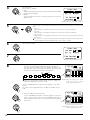
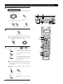
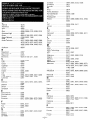
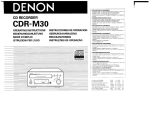
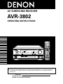
AV SURROUND RECEIVER
AVR-3802
OPERATING INSTRUCTIONS
POWER
ON /
SOURCE
OFF
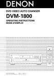
RC-883
REMOTE CONTROL UNIT
TV
CD
VCR
CDR/MD/ TAPE RECEIVER
DBS/CABLE
VDP
DVD
DISPLAY
MENU
SURR.
PARA.
OSD
SETUP
RETURN
TUNING
A/B
MEMORY
BAND
MODE
CHANNEL
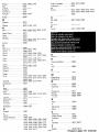
AVR-3802
PRECISION AUDIO COMPONENT / AV SURROUND RECEIVER
MASTER VOLUME
+
FUNCTION
SKIP
REMOTE
SENSOR
ON / STANDBY
TUNING
PRESET
REC /
MULTI
6.1 / 7.1
SURROUND
A
SURROUND
SPEAKER
AUTO
INPUT
PCM
VOLUME LEVEL
SURROUND
BACK CH
SIGNAL
OUTPUT
DIGITAL
SOURCE
VOLUME
TUNING
DTS
SIGNAL
DETECT
B
ENTER
-
SHIFT
SKIP
MUTING
TUNER
PHONO
+
CD
1
2
3
CDR/TAPE
VDP
DVD
4
5
6
VCR-1
VCR-2/V.AUX
TV/DBS
7
8
9
TV/
VCR
0
+10
TEST
TONE
SPEAKER
OUTPUT
SURROUND
ON / STANDBY
SURROUND
MODE
INPUT
PHONES
AUTO
PCM
DTS
ANALOG
EXT. IN
VIDEO SELECT
DIMMER
STATUS
SELECT
CH VOL
DOLBY/DTS
SURROUND
DSP
SIMU.
5CH / 7CH
STEREO
6.1 / 7.1
SURROUND
DIRECT
STEREO
MODE
ANALOG
TONE DEFEAT
SURROUND
PARAMETER
TONE
CONTROL
INPUT
EXT.IN
SYSTEM CALL
CALL 1
CALL 2
BACKLIGHT
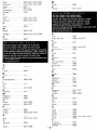
2 We greatly appreciate your purchase of the AVR-3802.
2 To be sure you take maximum advantage of all the features the AVR-3802 has to offer, read these instructions
carefully and use the set properly. Be sure to keep this manual for future reference, should any questions or
problems arise.
“SERIAL NO.
PLEASE RECORD UNIT SERIAL NUMBER ATTACHED TO THE REAR OF THE
CABINET FOR FUTURE REFERENCE”
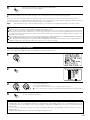
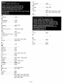
2 SAFETY PRECAUTIONS
CAUTION
WARNING:
TO PREVENT FIRE OR SHOCK HAZARD, DO NOT EXPOSE
THIS APPLIANCE TO RAIN OR MOISTURE.
TO PREVENT ELECTRIC SHOCK, MATCH WIDE BLADE OF PLUG
TO WIDE SLOT, FULLY INSERT.
ATTENTION
CAUTION
POUR ÉVITER LES CHOCS ÉLECTRIQUES, INTERODUIRE LA
LAME LA PLUS LARGE DE LA FICHE DANS LA BORNE
CORRESPONDANTE DE LA PRISE ET POUSSER JUSQU’ AU
FOND.
RISK OF ELECTRIC SHOCK
DO NOT OPEN
CAUTION: TO REDUCE THE RISK OF ELECTRIC SHOCK, DO
NOT REMOVE COVER (OR BACK). NO USERSERVICEABLE PARTS INSIDE. REFER SERVICING
TO QUALIFIED SERVICE PERSONNEL.
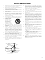
The lightning flash with arrowhead symbol, within an
equilateral triangle, is intended to alert the user to the
presence of uninsulated “dangerous voltage” within
the product’s enclosure that may be of sufficient
magnitude to constitute a risk of electric shock to
persons.
This device complies with Part 15 of the FCC Rules. Operation is subject to
the following two conditions: (1) This device may not cause harmful
interference, and (2) this device must accept any interference received,
including interference that may cause undesired operation.
This Class B digital apparatus meets all requirements of the Canadian
Interference-Causing Equipment Regulations.
Cet appareil numérique de la classe B respecte toutes les exigences du
Règlement sur le matériel brouilleur du Canada.
The exclamation point within an equilateral triangle is
intended to alert the user to the presence of important
operating and maintenance (servicing) instructions in
the literature accompanying the appliance.
2 NOTE ON USE / OBSERVATIONS RELATIVES A L’UTILISATION
• Avoid high temperatures.
Allow for sufficient heat dispersion when
installed on a rack.
• Eviter des températures élevées
Tenir compte d’une dispersion de chaleur
suffisante lors de l’installation sur une étagère.
• Keep the set free from moisture, water, and
dust.
• Protéger l’appareil contre l’humidité, l’eau et
lapoussière.
• Unplug the power cord when not using the set
for long periods of time.
• Débrancher le cordon d’alimentation lorsque
l’appareil n’est pas utilisé pendant de longues
périodes.
• Do not let foreign objects in the set.
• Ne pas laisser des objets étrangers dans
l’appareil.
• Do not let insecticides, benzene, and thinner
come in contact with the set.
• Ne pas mettre en contact des insecticides, du
benzène et un diluant avec l’appareil.
• Handle the power cord carefully.
Hold the plug when unplugging the cord.
• Manipuler le cordon d’alimentation avec
précaution.
Tenir la prise lors du débranchement du cordon.
* (For sets with ventilation holes)
• Do not obstruct the ventilation holes.
• Ne pas obstruer les trous d’aération.
2
• Never disassemble or modify the set in any
way.
• Ne jamais démonter ou modifier l’appareil
d’une manière ou d’une autre.
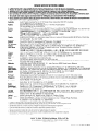
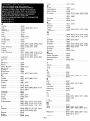
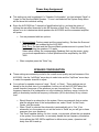
SAFETY INSTRUCTIONS
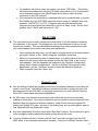
12.
Power-Cord Protection – Power-supply cords should be
routed so that they are not likely to be walked on or pinched
by items placed upon or against them, paying particular
attention to cords at plugs, convenience receptacles, and
the point where they exit from the appliance.
Heed Warnings – All warnings on the appliance and in the
operating instructions should be adhered to.
14.
Cleaning – The appliance should be cleaned only as
recommended by the manufacturer.
4.
Follow Instructions – All operating and use instructions
should be followed.
15.
Power Lines – An outdoor antenna should be located away
from power lines.
5.
Water and Moisture – The appliance should not be used
near water – for example, near a bathtub, washbowl,
kitchen sink, laundry tub, in a wet basement, or near a
swimming pool, and the like.
16.
6.
Carts and Stands – The appliance should be used only with
a cart or stand that is recommended by the manufacturer.
6A.
An appliance and cart
combination should be
moved with care.
Quick stops, excessive
force, and uneven
surfaces may cause
the appliance and cart
combination to overturn.
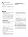
Outdoor Antenna Grounding – If an outside antenna is
connected to the receiver, be sure the antenna system is
grounded so as to provide some protection against voltage
surges and built-up static charges. Article 810 of the
National Electrical Code, ANSI/NFPA 70, provides
information with regard to proper grounding of the mast and
supporting structure, grounding of the lead-in wire to an
antenna-discharge unit, size of grounding conductors,
location of antenna-discharge unit, connection to grounding
electrodes, and requirements for the grounding electrode.
See Figure A.
17.
Nonuse Periods – The power cord of the appliance should
be unplugged from the outlet when left unused for a long
period of time.
1.
Read Instructions – All the safety and operating instructions
should be read before the appliance is operated.
2.
Retain Instructions – The safety and operating instructions
should be retained for future reference.
3.
7.
Wall or Ceiling Mounting – The appliance should be
mounted to a wall or ceiling only as recommended by the
manufacturer.
18.
Object and Liquid Entry – Care should be taken so that
objects do not fall and liquids are not spilled into the
enclosure through openings.
8.
Ventilation – The appliance should be situated so that its
location or position does not interfere with its proper
ventilation. For example, the appliance should not be
situated on a bed, sofa, rug, or similar surface that may
block the ventilation openings; or, placed in a built-in
installation, such as a bookcase or cabinet that may impede
the flow of air through the ventilation openings.
19.
9.
Heat – The appliance should be situated away from heat
sources such as radiators, heat registers, stoves, or other
appliances (including amplifiers) that produce heat.
Damage Requiring Service – The appliance should be
serviced by qualified service personnel when:
A. The power-supply cord or the plug has been damaged; or
B. Objects have fallen, or liquid has been spilled into the
appliance; or
C. The appliance has been exposed to rain; or
D. The appliance does not appear to operate normally or
exhibits a marked change in performance; or
E. The appliance has been dropped, or the enclosure
damaged.
10.
Power Sources – The appliance should be connected to a
power supply only of the type described in the operating
instructions or as marked on the appliance.
20.
11.
Grounding or Polarization – Precautions should be taken so
that the grounding or polarization means of an appliance is
not defeated.
Servicing – The user should not attempt to service the
appliance beyond that described in the operating
instructions. All other servicing should be referred to
qualified service personnel.
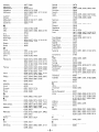
FIGURE A
EXAMPLE OF ANTENNA GROUNDING
AS PER NATIONAL
ELECTRICAL CODE
ANTENNA
LEAD IN
WIRE
GROUND
CLAMP
ANTENNA
DISCHARGE UNIT
(NEC SECTION 810-20)
ELECTRIC
SERVICE
EQUIPMENT
GROUNDING CONDUCTORS
(NEC SECTION 810-21)
GROUND CLAMPS
POWER SERVICE GROUNDING
ELECTRODE SYSTEM
(NEC ART 250, PART H)
NEC - NATIONAL ELECTRICAL CODE
3
2 INTRODUCTION
Thank you for choosing the DENON Digital Surround A / V receiver. This remarkable component has been engineered to provide superb surround
sound listening with home theater sources such as DVD, as well as providing outstanding high fidelity reproduction of your favorite music sources.
As this product is provided with an immense array of features, we recommend that before you begin hookup and operation that you review the
contents of this manual before proceeding.
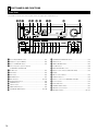
TABLE OF CONTENTS
z
x
c
v
b
n
m
,
.
Before Using ...............................................................................................4
Cautions on Installation ...............................................................................4
Cautions on Handling ..................................................................................5
Features ......................................................................................................5
Connections ..........................................................................................6~13
Part Names and Functions..................................................................14, 15
Setting up the system ........................................................................16~28
Remote Control Unit...........................................................................29~40
⁄0
⁄1
⁄2
⁄3
⁄4
⁄5
⁄6
⁄7
Surround .............................................................................................49~53
DSP Surround Simulation ...................................................................54~59
Listening to the Radio.........................................................................60~62
Last Function Memory ..............................................................................62
Initialization of the Microprocessor ...........................................................62
Troubleshooting.........................................................................................63
Additional Information.........................................................................64~72
Specifications ............................................................................................73
Operation ............................................................................................41~48
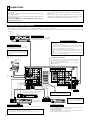
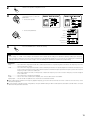
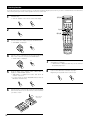
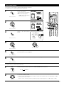
2 ACCESSORIES
Check that the following parts are included in addition to the main unit:
q Operating instructions…..1
t R6P/AA batteries .............3
w Warranty ( for North America model only )………...........1
y AM loop antenna…...............1 u FM indoor antenna…1
r
t
e Service station list…….....1
i FM antenna adaptor….....1
y
u
r Remote control unit
(RC-883)............…......1
i
1 BEFORE USING
Pay attention to the following before using this unit:
• Moving the set
To prevent short circuits or damaged wires in the connection cords,
always unplug the power cord and disconnect the connection cords
between all other audio components when moving the set.
• Store this instructions in a safe place.
After reading, store this instructions along with the warranty in a
safe place.
• Before turning the power switch on
Check once again that all connections are proper and that there are
not problems with the connection cords. Always set the power
switch to the standby position before connecting and disconnecting
connection cords.
• Note that the illustrations in this instructions may differ from
the actual set for explanation purposes.
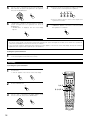
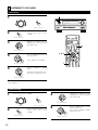
2 CAUTIONS ON INSTALLATION
4 inch/10 cm or more
Noise or disturbance of the picture may be generated if this unit or
any other electronic equipment using microprocessors is used near a
tuner or TV.
If this happens, take the following steps:
• Install this unit as far as possible from the tuner or TV.
• Set the antenna wires from the tuner or TV away from this unit’s
power cord and input/output connection cords.
• Noise or disturbance tends to occur particularly when using indoor
antennas or 300 Ω/ohms feeder wires. We recommend using
outdoor antennas and 75 Ω/ohms coaxial cables.
For heat dispersal, leave at least 4 inch/10 cm of space between
the top, back and sides of this unit and the wall or other
components.
4
B
4 inch/10 cm or more
Wall
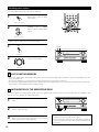
3 CAUTIONS ON HANDLING
• Switching the input function when input jacks are not
connected
A clicking noise may be produced if the input function is switched
when nothing is connected to the input jacks. If this happens, either
turn down the MASTER VOLUME control or connect components
to the input jacks.
• Whenever the power switch is in the STANDBY state, the
apparatus is still connected on AC line voltage.
Please be sure to unplug the cord when you leave home for,
say, a vacation.
• Muting of PRE OUT jacks, HEADPHONE jack and SPEAKER
terminals
The PRE OUT jacks, HEADPHONE jacks and SPEAKER terminals
include a muting circuit. Because of this, the output signals are
greatly reduced for several seconds after the power switch is
turned on or input function, surround mode or any other-set-up is
changed. If the volume is turned up during this time, the output will
be very high after the muting circuit stops functioning. Always wait
until the muting circuit turns off before adjusting the volume.
4 FEATURES
1. Digital Surround Sound Decoding
Featuring 32 bit high speed DSP, operating entirely in digital
domain, surround sound from digital sources such as DVD, LD,
DTV and satellite are faithfully re-created.
2. Dolby Pro Logic II decoder
Dolby Pro Logic II is a new format for playing multichannel audio
signals that offers improvements over conventional Dolby Pro
Logic. It can be used to decode not only sources recorded in Dolby
Surround but also regular stereo sources into five channels (front
left/right, center and surround left/right). In addition, various
parameters can be set according to the type of source and the
contents, so you can adjust the sound field with greater precision.
3. Dolby Digital
Using advanced digital processing algorithms, Dolby Digital
provides up to 5.1 channels of wide-range, high fidelity surround
sound. Dolby Digital is the default digital audio delivery system for
North American DVD and DTV.
4. DTS (Digital Theater Systems)
DTS provides up to 5.1 channels of wide-range, high fidelity
surround sound, from sources such as laser disc, DVD and
specially-encoded music discs.
5. DTS-ES Extended Surround and DTS Neo:6
The AVR-3802 is compatible with DTS-ES Extended Surround, a new
multi-channel format developed by Digital Theater Systems Inc.
The AVR-3802 is also compatible with DTS Neo:6, a surround mode
allowing 6.1-channel playback of regular stereo sources.
6. Wide screen mode for a 7.1-channel sound even with
5.1-channel sources
DENON has developed a wide screen mode with a new design
which recreates the effects of the multi surround speakers in
movie theaters. The result is 7.1-channel sound taking full
advantage of surround back speakers, even with Dolby Pro Logic
or Dolby Digital/DTS 5.1-channel signals.
7. 24 bit D/A Conversion
All six channels, including the five main channels and the low
frequency effects (LFE) channel benefit from reference, for
optimum high fidelity reproduction of music and movie
soundtracks.
diffusion pattern (bipolar dispersion) or by using surround
speakers that provide broad dispersion with a minimum of onaxis localization (dipolar dispersion). Side wall mounting (closer
to the ceiling) of the surround speakers provides the greatest
envelopment, minimizing localization of direct sound from the
speakers.
(2) Music Surround
With full range discrete surround channels, as well as three
discrete full range front channels, digital formats such as Dolby
and DTS offer thrilling surround sound music listening.
Producers of multi-channel discrete digital music recordings
almost always favor the use of direct radiating (monopolar)
surround speakers, placed in the rear corners of the room,
since that is how they configure their studios during the
mixing/creation process.
The DENON AVR-3802 provides the ability to connect two
different sets of surround speakers, and place them in the
appropriate locations in your AV theater room, so that you can
enjoy both movie soundtracks and music listening, with
optimum results and no compromise.
9. Component Video Switching
In addition to composite video and “S” video switching, the AVR3802 provides 2 sets of component video (Y, PB/CB, PR/CR) inputs
for the DVD and TV/DBS inputs, and one set of component video
outputs to the television, for superior picture quality.
10.Video Select Function
Allow you to watch one source (visual) while listening to another
source (audio).
11.Future Sound Format Upgrade Capability via Eight Channel
Inputs & Outputs
For future multi-channel audio format(s), the AVR-3802 is provided
with 7.1 channel (seven main channels, plus one low frequency
effects channel) inputs, along with a full set of 7.1 channel pre-amp
outputs, controlled by the 8 channel master volume control. This
assures future upgrade possibilities for any future multi-channel
sound format.
8. Dual Surround Speaker Mode
Provides for the first time the ability to optimize surround sound
reproduction using two different types of surround sound speakers
as well as two different surround speaker positions:
(1) Movie Surround
Motion picture soundtracks use the surround channel(s) to
provide the ambient elements of the acoustic environment they
want the audience to realize. This is best accomplished by the
use of specially-designed surround speakers that offer a wide
5
5 CONNECTIONS
• Do not plug in the AC cord until all connections have been
completed.
• Be sure to connect the left and right channels properly (left with
left, right with right).
• Insert the plugs securely. Incomplete connections will result in the
generation of noise.
• Use the AC OUTLETS for audio equipment only. Do not use
them for hair driers, etc.
• Note that binding pin plug cords together with AC cords or placing
them near a power transformer will result in generating hum or
other noise.
• Noise or humming may be generated if a connected audio
equipment is used independently without turning the power of this
unit on. If this happens, turn on the power of the this unit.
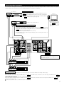
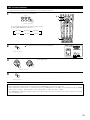
Connecting the audio components
• When making connections, also refer to the operating instructions of the other components.
The power to these outlets is turned on and off when the power is switched between on and standby from the remote control unit or power
switch.
OUTPUT
R
CD player
L
Connecting a CD player
Connect the CD player’s analog output
jacks (ANALOG OUTPUT) to this unit’s CD
jacks using pin plug cords.
DIGITAL AUDIO
R
L
Connecting the AC OUTLETS
AC OUTLETS
• SWITCHED
(total capacity – 120 W (1 A.))
The power to these outlets is turned on and off in conjunction with the
POWER operation switch on the main unit, and when the power is switched
between on and standby from the remote control unit.
No power is supplied from these outlets when this unit’s power is at standby.
Never connect equipment whose total capacity is above 120 W (1 A.).
NOTE:
Only use the AC OUTLETS for audio equipment. Never use them for hair
driers, TVs or other electrical appliances.
Connecting a turntable
Connect the turntable’s output cord to the AVR3802’s PHONO jacks, the L (left) plug to the L jack,
the R (right) plug to the right jack.
NOTE:
This unit cannot be used with MC cartridges
directly. Use a separate head amplifier or step-up
transformer.
If humming or other noise is generated when the
ground wire is connected, disconnect the ground
wire.
Connecting the pre-out jacks
Use these jacks if you wish to connect external power amplifier(s) to
increase the power of the front, center and surround sound channels, or
for connection to powered loudspeakers.
To use Surround back with one speaker, connect the speaker to
SURR. BACK L CH.
Turntable
(MM cartridge)
L
R
L
R
Ground
wire
L
R
R
L
AC CORD
AC 120 V, 60 Hz
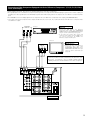
MD recorder, CD recorder or other component
equipped with digital input/output jacks
Route the connection cords, etc., in such a way
that they do not obstruct the ventilation holes.
B
OUTPUT
INPUT
OPTICAL
R
DIGITAL AUDIO
OPTICAL COAXIAL
OUTPUT
CD player or other
component equipped
with digital output jacks
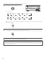
Connecting the DIGITAL jacks
Use these for connections to audio equipment with digital output. Refer to page 25 for
instructions on setting this terminal.
NOTES:
• Use 75 Ω/ohms cable pin cords for coaxial connections.
• Use optical cables for optical connections, removing the cap before connecting.
6
L
R
L
CD recorder or Tape deck
B
R
INPUT
L
R
L
OUTPUT
NOTE:
If humming noise is generated by a
tape deck, etc., move the tape deck
away.
Connecting a tape deck
Connections for recording:
Connect the tape deck’s recording input jacks (LINE IN or REC) to this unit’s tape
recording (CDR/TAPE OUT) jacks using pin plug cords.
Connections for playback:
Connect the tape deck’s playback output jacks (LINE OUT or PB) to this unit’s tape
playback (CDR/TAPE IN) jacks using pin plug cords.
Connecting video components
• To connect the video signal, connect using a 75 Ω/ohms video signal cable cord. Using an improper cable can result in a drop in video quality.
• When making connections, also refer to the operating instructions of the other components.
Connecting a TV/DBS tuner
TV/DBS
• Connect the TV’s or DBS tuner’s video output jack (VIDEO OUTPUT) to the
VIDEO (yellow) TV/DBS IN jack using a 75 Ω/ohms video coaxial pin plug
cord.
• Connect the TV’s or DBS tuner’s audio output jacks (AUDIO OUTPUT) to
the AUDIO TV/DBS IN jacks using pin plug cords.
TV or DBS tuner
AUDIO
R
R
OUT
L
VIDEO
OUT
B
L
AUDIO
OUT
R
L
VIDEO
OUT
Monitor TV
VIDEO
IN
B
DVD player or video disc player (VDP), etc.
L
R
Connecting a DVD player or a video disc player (VDP)
DVD
• Connect the video disc player’s video output jack (VIDEO OUTPUT) to the VIDEO (yellow) DVD IN
jack using a 75 Ω/ohms video coaxial pin plug cord.
• Connect the video disc player’s analog audio output jacks (ANALOG AUDIO OUTPUT) to the
AUDIO DVD IN jacks using pin plug cords.
• A VDP can be connected to the VDP jacks in the same way.
• It is also possible to connect a video disc player, DVD player, video camcorder, game machine, etc.,
to the VCR-2/V.AUX jacks.
MONITOR OUT
• Connect the TV’s video
input jack (VIDEO INPUT) to
VIDEO
the
MONITOR
OUT jack using a 75
Ω/ohms video coaxial pin
plug cord.
R
L
R
L
R
L
R
L
R
L
R
L
Note on connecting the digital input jacks
• Only audio signals are input to the digital input jacks.
For details, see page 6.
R
R
OUT
L
R
L
R
IN
L
AUDIO
R
R
OUT
L
R
L
R
AUDIO
Video deck 2
L
OUT IN
VIDEO
Video deck 1
L
IN
L
OUT IN
VIDEO
Connecting a video decks
• There are two sets of video deck (VCR) jacks, so two video decks can be connected for simultaneous recording or video copying.
Video input/output connections:
• Connect the video deck’s video output jack (VIDEO OUT) to the VIDEO (yellow) VCR-1 IN jack, and the video deck’s video input jack (VIDEO IN) to the VIDEO
(yellow) VCR-1 OUT jack using 75 Ω/ohms video coaxial pin plug cords.
Connecting the audio output jacks
• Connect the video deck’s audio output jacks (AUDIO OUT) to the AUDIO VCR-1 IN jacks, and the video deck’s audio input jacks (AUDIO IN) to the AUDIO VCR-1
OUT jacks using pin plug cords.
Connect the second video deck to the VCR-2/V.AUX jacks in the same way.
7
Connecting a video component equipped with S-Video jacks
• When making connections, also refer to the operating instructions of the other components.
• A note on the S input jacks
The input selectors for the S inputs and pin jack inputs work in conjunction with each other.
• Precaution when using S-jacks
This unit’s S-jacks (input and output) and video pin jacks (input and output) have independent circuit structures, so that video signals input from
the S-jacks are only output from the S-jack outputs and video signals input from the pin jacks are only output from the pin jack outputs.
When connecting this unit with equipment that is equipped with S-jacks, keep the above point in mind and make connections according to the
equipment’s instruction manuals.
DVD player or video disc player (VDP)
S-VIDEO
B
Connecting a monitor TV
MONITOR OUT
• Connect the TV’s S video input (S-VIDEO INPUT) to the S-VIDEO MONITOR
OUT jack using a S jack connection cord.
OUT
Connecting a DVD player or a video disc player (VDP)
DVD
• Connect the DVD player’s S-Video output jack to the S-VIDEO
DVD IN jack using an S-Video connection cord.
• A VDP can be connected to the VDP jacks in the same way.
• It is also possible to connect a video disc player, DVD player,
video camcorder, game machine, etc., to the VCR-2/V.AUX
jacks.
S-VIDEO
IN
Monitor TV
TV or satellite broadcast tuner
S-VIDEO
B
OUT
Connecting a TV/DBS tuner
• Connect the TV’s or DBS tuner’s S video output jack (SVIDEO OUTPUT) to the S-VIDEO TV/DBS IN jack
using an S jack connection cord.
S-VIDEO
OUT
IN
Video deck 1
Connecting the video decks
• Connect the video deck’s S output jack (S-OUT) to the
S-VIDEO VCR-1 IN jack and the video deck’s S input jack
(S-IN) to the S-VIDEO VCR-1 OUT jack using S jack
connection cords.
• Connect the video deck’s S output jack (S-OUT) to the
S-VIDEO VCR-2/V.AUX IN jack and the video deck’s S input
jack (S-IN) to the S-VIDEO VCR-2/V.AUX OUT jack using S
jack connection cords.
S-VIDEO
OUT
IN
Connect the components’ audio inputs and outputs as described on page 7.
8
Video deck 2
Connecting a Video Component Equipped with Color Difference (Component - Y, PR/CR, PB/CB) Video
Jacks (DVD Player)
• When making connections, also refer to the operating instructions of the other components.
• The signals input to the color difference (component) video jacks are not output from the VIDEO output jack (yellow) or the S-Video output jack.
In addition, the video signals input to the VIDEO input (yellow) and S-Video input jacks are not output to the color difference (component) video
jacks.
• The AVR-3802’s on-screen display signals are not output from the color difference (component) video output jacks (MONITOR OUT).
• Some video sources with component video outputs are labeled Y, CB, CR, or Y, Pb, Pr, or Y, R-Y, B-Y. These terms all refer to component video
color difference output.
COMPONENT
VIDEO OUT
DVD player
Connecting a DVD player
DVD IN jacks
• Connect the DVD player’s color difference
(component) video output jacks (COMPONENT
VIDEO OUTPUT) to the COMPONENT DVD IN jack
using 75 Ω/ohms coaxial video pin-plug cords.
• In the same way, another video source with
component video outputs such as a TV/DBS tuner,
etc., can be connected to the TV/DBS color
difference (component) video jacks.
B
CR
CB
Y
Monitor TV
COMPONENT
VIDEO IN
CB
CR
Y
Connecting a monitor TV
MONITOR OUT jack
• Connect the TV’s color difference
(component) video input jacks
(COMPONENT VIDEO INPUT) to the
COMPONENT MONITOR OUT jack
using 75 Ω/ohms coaxial video pinplug cords.
• The color difference input jacks may be indicated differently on
some TVs, monitors or video components (“CR, CB and Y”, “R-Y,
B-Y and Y”, “Pr, Pb and Y”, etc.). For details, carefully read the
operating instructions included with the TV or other component.
9
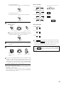
Connecting the antenna terminals
DIRECTION OF
BROADCASTING
STATION
AM LOOP
ANTENNA
(Supplied)
FM ANTENNA
75 Ω/ohms
COAXIAL
CABLE
300 Ω/ohms
FEEDER
CABLE
FM ANTENNA
ADAPTER
(Supplied)
AM OUTDOOR
ANTENNA
FM INDOOR
ANTENNA
(Supplied)
300 Ω/ohms
GROUND
• An F-type FM antenna cable plug can be connected directly.
• If the FM antenna cable’s plug is not of the F-type, connect using the included antenna adapter.
AM loop antenna assembly
1
2
FM antenna adapter assembly
75 Ω/ohms COAXIAL CABLE
Connect to the AM
antenna terminals.
3
Open the cover
SHUT
PULL
4
Remove the vinyl tie
and take out the
connection line.
Bend in the reverse
direction.
CLAMP
CLAMP
m
m
14
m
m
19
PULL
m
9m
ANTENNA ADAPTER
a. With the antenna
on top any stable
surface.
m
5m
REMOVE
Mount
3C-2V
m
m
14
m
5m
5C-2V
CLAMP
b. With the antenna
attached to a wall.
Installation hole
Mount on wall, etc.
Connection of AM antennas
1. Push the lever. 2. Insert the conductor. 3. Return the lever.
Note to CATV system installer:
This reminder is provided to call the CATV system installer’s
attention to Article 820-40 of the NEC which provides guidelines
for proper grounding and, in particular, specifies that the cable
ground shall be connected to the grounding system of the
building, as close to the point of cable entry as practical.
Notes:
• Do not connect two FM antennas simultaneously.
• Even if an external AM antenna is used, do not disconnect the
AM loop antenna.
• Make sure AM loop antenna lead terminals do not touch metal
parts of the panel.
10
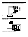
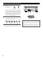
Connecting the external input (EXT. IN) jacks
• These jacks are for inputting multi-channel audio signals from an outboard decoder, or a component with a different type of multi-channel
decoder, such as a Super Audio DVD player, or a multi-channel SACD player, or other future multi-channel sound format decoder.
• When making connections, also refer to the operating instructions of the other components.
R
L
R
L
L
Center
Subwoofer
Surround back
Surround
Front
R
Decoder with 8- or 6-channel analog
output
For instructions on playback using the external input (EXT. IN) jacks, see page 44.
Connecting the MULTI ZONE jacks
• If another pre-main (integrated) amplifier or power amplifier is connected, the multi-source jacks can be used to play a different program source
in another room at the same time.
Another room
Integrated pre-main amplifier or power amplifier
B
L
R
For instructions on operations using the MULTI ZONE jacks, see page 46 ~ 48.
11
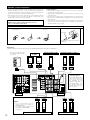
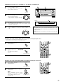
Speaker system connections
• Connect the speaker terminals with the speakers making sure that like
polarities are matched (≈ with ≈ , √ with √ ). Mismatching of polarities will
result in weak central sound, unclear orientation of the various instruments,
and the sense of direction of the stereo being impaired.
• When making connections, take care that none of the individual conductors
of the speaker cord come in contact with adjacent terminals, with other
speaker cord conductors, or with the rear panel.
Speaker Impedance
• Speakers with an impedance of from 6 to 16 Ω/ohms can be connected for
use as front and center speakers.
• Speakers with an impedance of 6 to 16 Ω/ohms can be connected for use as
surround speakers.
• Be careful when using two pairs of surround speakers (A + B) at the same
time, since use of speakers with an impedance of less than 8 Ω/ohms will
lead to damage.
• The protector circuit may be activated if the set is played for long periods of
time at high volumes when speakers with an impedance lower than the
specified impedance are connected.
NOTE:
NEVER touch the speaker terminals when the power is on.
Doing so could result in electric shocks.
Connection the speaker terminals
1. Loosen by turning
counterclockwise
2. Insert the cord.
3. Tighten by turning
clockwise.
Connecting banana plugs
banana plug
Turn clockwise to tighten, then insert the
banana plug.
Connections
• When making connections, also refer to the operating instructions of the other components.
Connection jack for subwoofer
with built-in amplifier (super
woofer), etc.
FRONT SPEAKER
SYSTEMS
(L)
CENTER SPEAKER SYSTEM
(R)
SURROUND SPEAKER SYSTEMS (A)
(L)
(R)
• Precautions when
connecting speakers
If a speaker is placed near a
TV or video monitor, the
colors on the screen may
be disturbed by the
speaker’s magnetism. If
this should happen, move
the speaker away to a
position where it does not
have this effect.
NOTES:
• To use Surround back with one
speaker, connect the speaker to
SURR. BACK L CH.
• The settings must be changed to use
this speaker for MULTI ZONE.
See page 18.
(L)
(R)
SURROUND BACK/MULTI ZONE SPEAKER SYSTEMS
12
(L)
(R)
SURROUND SPEAKER SYSTEMS (B)
Protector circuit
• This unit is equipped with a high-speed protection circuit. The purpose of this circuit is to protect the speakers under
circumstances such as when the output of the power amplifier is inadvertently short-circuited and a large current flows, when
the temperature surrounding the unit becomes unusually high, or when the unit is used at high output over a long period
which results in an extreme temperature rise.
When the protection circuit is activated, the speaker output is cut off and the power supply indicator LED flashes. Should
this occur, please follow these steps: be sure to switch off the power of this unit, check whether there are any faults with
the wiring of the speaker cables or input cables, and wait for the unit to cool down if it is very hot. Improve the ventilation
condition around the unit and switch the power back on.
If the protection circuit is activated again even though there are no problems with the wiring or the ventilation around the
unit, switch off the power and contact a DENON service center.
Note on speaker impedance
• The protector circuit may be activated if the set is played for long periods of time at high volumes when speakers with an
impedance lower than the specified impedance (for example speakers with an impedance of lower than 4 Ω/ohms) are
connected. If the protector circuit is activated, the speaker output is cut off. Turn off the set’s power, wait for the set to cool
down, improve the ventilation around the set, then turn the power back on.
13
6 PART NAMES AND FUNCTIONS
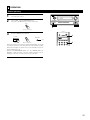
Front Panel
• For details on the functions of these parts, refer to the pages given in parentheses ( ).
@9 @8 @7
@6 @5 @4 @3
@2 @1
@0
!9
AVR-3802
PRECISION AUDIO COMPONENT / AV SURROUND RECEIVER
MASTER VOLUME
FUNCTION
REMOTE
SENSOR
ON / STANDBY
SOURCE
TUNING
PRESET
REC /
MULTI
6.1 / 7.1
SURROUND
A
SURROUND
SPEAKER
AUTO
OUTPUT
DTS
SIGNAL
DETECT
B
SURROUND
MODE
INPUT
PHONES
ON / STANDBY
INPUT
PCM
VOLUME LEVEL
SURROUND
BACK CH
SIGNAL
DIGITAL
AUTO
PCM
DTS
ANALOG
EXT. IN
VIDEO SELECT
DIMMER
STATUS
SURROUND
PARAMETER
q
w er t y u i o !0 !1 !2 !3
q Power ON/STANDBY switch....................................................(41)
w Headphones jack (PHONES) ....................................................(45)
e 6.1/7.1 SURROUND button......................................................(52)
r Surround speaker system indicators
(SURROUND SPEAKER A/B)
t AUTO button ............................................................................(42)
y PCM button ..............................................................................(43)
u DTS button ...............................................................................(43)
i ANALOG button .......................................................................(42)
o EXT. IN button ....................................................................(42, 44)
!0 VIDEO SELECT button .............................................................(46)
!1 DIMMER button .......................................................................(46)
!2 STATUS button .........................................................................(46)
!3 TONE DEFEAT button ..............................................................(45)
!4 SURROUND MODE button................................................(43, 50)
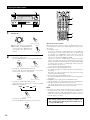
14
SELECT
CH VOL
TONE DEFEAT
TONE
CONTROL
!4 !5 !6 !7 !8
!5 SURROUND PARAMETER button ...........................................(51)
!6 SELECT knob............................................................................(43)
!7 TONE CONTROL button ..........................................................(45)
!8 CH VOL button.........................................................................(49)
!9 MASTER VOLUME control ......................................................(43)
@0 Master volume indicator (VOLUME LEVEL) ............................(43)
@1 Display
@2 INPUT mode indicators ............................................................(43)
@3 SIGNAL indicators ....................................................................(43)
@4 Remote control sensor (REMOTE SENSOR) ...........................(29)
@5 Power indicator ........................................................................(41)
@6 FUNCTION knob.......................................................................(42)
@7 TUNING PRESET button ..........................................................(62)
@8 SOURCE selector button .........................................................(42)
@9 REC/MULTI button .............................................................(46, 47)
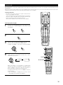
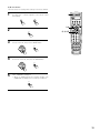
Remote control unit
• For details on the functions of these parts, refer to the pages given in parentheses ( ).
Remote control signal
transmitter ..............................................(29)
POWER
Power button..........................................(41)
ON /
SOURCE
OFF
RC-883
REMOTE CONTROL UNIT
DISPLAY/SURR. PARA
button .....................................................(51)
System setup/
system buttons ......................................(16)
TV
CD
VCR
DBS/CABLE
CDR/MD/ TAPE RECEIVER
VDP
DVD
DISPLAY
MENU
SURR.
PARA.
OSD
SETUP
MENU/OSD button.................................(46)
RETURN
TUNING
A/B
MEMORY
Tuner system/
system button ........................................(16)
BAND
RETURN/MEMORY/system
buttons ...................................................(61)
MODE
CHANNEL
VOLUME
TUNING
+
SKIP
ENTER
+
System buttons ......................................(61)
ENTER/system button............................(16)
Mode selector buttons ...........................(32)
SKIP
MUTING
-
TUNER
PHONO
CD
1
2
3
CDR/ TAPE
VDP
DVD
4
5
6
VCR-1
VCR-2 /V.AUX
TV/DBS
7
8
9
TV/
VCR
0
+10
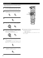
SHIFT
Master volume control
buttons ...................................................(43)
MUTING button......................................(45)
Input source selector
buttons ...................................................(42)
Speaker selector button .........................(55)
TEST TONE button .................................(49)
TEST
TONE
SPEAKER
OUTPUT
OUTPUT button......................................(45)
SURROUND
DOLBY/DTS
SURROUND
DSP
SIMU.
5CH / 7CH
STEREO
6.1 / 7.1
SURROUND
DIRECT
STEREO
MODE
ANALOG
Surround mode buttons .........................(55)
INPUT
Input mode selector buttons..................(42)
EXT.IN
SYSTEM CALL
SYSTEM CALL buttons ..........................(35)
CALL 1
CALL 2
BACKLIGHT
BACKLIGHT button
15
7 SETTING UP THE SYSTEM
• Once all connections with other AV components have been completed as described in “CONNECTIONS” (see pages 6 to 13), make the various
settings described below on the monitor screen using the AVR-3802’s on-screen display function.
These settings are required to set up the listening room’s AV system centered around the AVR-3802.
• Use the following buttons to set up the system:
SYSTEM SETUP button
Press this to display the system setup menu.
MENU
DISPLAY
SURR.
PARA.
OSD
SETUP
CURSOR buttons
RETURN
TUNING
A/B
F and G:
MEMORY
BAND
+
SKIP
Use these to move the cursors (F and G) to the
left and right on the screen.
MODE
CHANNEL
VOLUME
D and H:
TUNING
ENTER
+
-
SHIFT
SKIP
MUTING
-
TUNER
PHONO
CD
Use these to move the cursors (D and H) to the
up and down on the screen.
ENTER button
Press this to switch the display.
Also use this button to complete the setting.
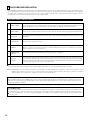
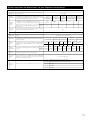
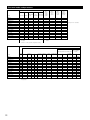
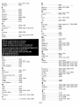
• System setup items and default values (set upon shipment from the factory)
System setup
q
w
Default settings
Power AMP
Assignment
Set this to switch the surround back channel’s power amplifier for
use for multi-zone.
Speaker
Configuration
Input the combination of speakers in your system and their
corresponding sizes (SMALL for regular speakers, LARGE for fullsize, full-range) to automatically set the composition of the signals
output from the speakers and the frequency response.
Surround
Speaker
Setting
Use this function when using multiple surround speaker
combinations for more ideal surround sound. Once the
combinations of surround speakers to be used for the
different surround modes are preset, the surround
speakers are selected automatically according to the
surround mode.
Small
Small / 2spkrs
Yes
Surround
speaker
A
A
A
A
—
—
r
Delay Time
This parameter is for optimizing the timing with which the audio
signals are produced from the speakers and subwoofer according to
the listening position.
This adjusts the volume of the signals output from the speakers and
subwoofer for the different channels in order to obtain optimum
effects.
80 Hz
LFE
DTS-ES / 6.1 Source Auto = OFF
Front L & R
Center
Surround L & R
SBL & SBR
Sub Woofer
12 ft (3.6 m)
12 ft (3.6 m)
10 ft (3.0 m)
10 ft (3.0 m)
12 ft (3.6 m)
Front L
Front R
Center
Surround
L
Surround
R
Surround
Back L
Surround
Back R
Subwoofer
0 dB
0 dB
0 dB
0 dB
0 dB
0 dB
0 dB
0 dB
Input
source
CD
DVD
TV/DBS
CDR/TAPE
VDP
VCR-1
VCR-2
—
—
Digital
Inputs
COAXIAL
OPTICAL 1
OPTICAL 2
OPTICAL 3
OFF
OFF
OFF
—
—
u
Multi
vol. Level
This sets the output level for the multi output jacks.
i
On Screen
Display
This sets whether or not to display the on-screen display that
appears on the monitor screen when the controls on the remote
control unit or main unit are operated.
16
Small
—
e
Auto Tuner
Presets
Large
—
Set the method of playing the surround back channel for digital
signals.
o
Sub Woofer
EXT. IN
This selects the subwoofer speaker for playing deep bass signals.
This assigns the digital input jacks for the different input
sources.
Surround Back Sp.
DSP
SIMULATION
SB CH Auto
Flag Detect
Digital In
Assignment
Surround Sp.
A/B
5CH/7CH
STEREO
Subwoofer mode
y
Center Sp.
DOLBY/
DTS
SURROUND
Set the frequency (Hz) below which the bass sound of the various
speakers is to be output from the subwoofer.
Channel
Level
Front Sp.
Surround
mode
Crossover
Frequency
t
Surround Back
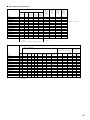
FM stations are received automatically and stored in the memory.
0 dB
On Screen Display = ON
A1 ~ A8
87.5/89.1/98.1/107.9/90.1/90.1/90.1/90.1 MHz
B1 ~B8
520/600/1000/1400/1500/1710 kHz, 90.1/90.1 MHz
C1 ~C8
90.1 MHz
D1 ~D8
90.1 MHz
E1 ~E8
90.1 MHz
NOTES:
• The on-screen display signals are not output from the color difference (component) video signal (MONITOR OUT) jacks.
• The on-screen display signals are output with priority to the S-VIDEO MONITOR OUT jack during playback of a video component. For example, if the TV monitor
is connected to both the AVR-3802’s S-Video and video monitor output jacks and signals are input to the AVR-3802 from a video source (VDP, etc.) connected to
both the S-Video and video input jacks, the on-screen display signals are output with priority to the S-Video monitor output. If you wish to output the signals to
the video monitor output jack, do not connect a cord to the S-VIDEO MONITOR OUT jack. (For details, see page 28.)
• The AVR-3802’s on-screen display function is designed for use with high resolution monitor TVs, so it may be difficult to read small characters on TVs with small
screens or low resolutions.
• The setup menu is not displayed when “HEADPHONE ONLY” is selected.
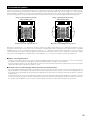
• Speaker system layout
Basic system layout
• The following is an example of the basic layout for a system consisting of eight speaker systems and a television monitor:
Subwoofer
Center speaker system
Surround back speaker systems
Front speaker systems
Set these at the sides of the TV or screen with
their front surfaces as flush with the front of the
screen as possible.
Surround speaker systems
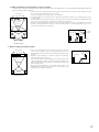
With the AVR-3802 it is also possible to use the surround speaker selector function to choose the best layout for a variety of sources and surround
modes.
• Surround speaker selector function
This function makes it possible to achieve the optimum sound fields for different sources by switching between two systems of surround
speakers (A and B).
A
B
A
SB
SB
Using A only
B
A
B
A
SB
SB
B
SB: SURROUND BACK SPEAKER
Using B only
17
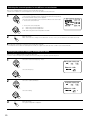
Before setting up the system
1
2
Check that all the connections are correct, then turn on the main unit’s power.
Display the System Setup Menu.
SETUP
Setting the power amplifier assignment
Make this setting to switch the power amplifier for the surround back channel to Multi.
1
TUNING
BAND
ENTER
MODE
At the System Setup Menu, select “Power Amp
Assignment” and press the ENTER button
SHIFT
TUNING
2
Select “Surround Back” to use as the surround back
channel, “Multi” to use as multi zone out.
TUNING
BAND
MODE
TUNING
When “Surround Back” is selected
3
When “Multi” is selected
Enter the setting.
The System Setup Menu reappears.
ENTER
SHIFT
Setting the type of speakers
• The composition of the signals output from the different channels and the frequency response are adjusted automatically according to the
combination of speakers actually being used.
1
At the System Setup Menu select “Speaker Configuration”.
TUNING
BAND
MODE
TUNING
18
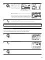
2
Switch to the speaker configuration screen.
ENTER
SHIFT
3
TUNING
BAND
MODE
Set whether or not speakers are
connected and, if so, their size
parameters.
• To select the speaker
TUNING
• To select the parameter
Center Sp.
TUNING
Front Sp.
BAND
MODE
Subwoofer
TUNING
Surround Sp. A
Surround back Sp.
Surround Sp. B
4
ENTER
Press the ENTER button to finalize the setting.
SHIFT
NOTE:
• Select “Large” or “Small” not according to the actual size of the speaker but according to the speaker’s capacity for playing low frequency
(bass sound below frequency set for the Crossover Frequency mode and below) signals. If you do not know, try comparing the sound at both
settings (setting the volume to a level low enough so as not to damage the speakers) to determine the proper setting.
• Parameters
Large...................Select this when using speakers that have sufficient performance for reproducing bass sound below the frequency set for the
Crossover Frequency mode.
Small...................Select this when using speakers that do not have sufficient performance for reproducing bass sound below the frequency set
for the Crossover Frequency mode. When this is set, bass sound with a frequency below the frequency set for the Crossover
Frequency mode is sent to the subwoofer.
When this setting is selected, low frequencies of below the frequency set for the Crossover Frequency mode are assigned
to the subwoofer.
None……............Select this when no speakers are installed.
Yes/No….............Select “Yes” when a subwoofer is installed, “No” when a subwoofer is not installed.
2spkrs/1spkr .......Set the number of speakers to be used for the surround back channel.
If the subwoofer has sufficient low frequency playback capacity, good sound can be achieved even when “Small” is set for the front, center
and surround speakers.
For the majority of speaker system configurations, using the SMALL setting for all five main speakers and Subwooofer On with a connected
subwoofer will yield the best results.
19
Selecting the surround speakers for the different surround modes
This screen is displayed when using both surround speakers A and B.
• At this screen preset the surround speakers to be used in the different surround modes.
1
TUNING
BAND
MODE
TUNING
TUNING
BAND
MODE
When either “Large” or “Small” has been set for both speakers A and B
on the System Setup Menu (when using both A and B surround speakers),
the surround speaker setting screen appears.
Select the surround speakers to be used in the different surround modes.
• To select the surround mode
• To select the surround speaker
A:
When using surround speakers A
B:
When using surround speakers B
A+B: When using both surround speakers A and B
TUNING
2
Enter the setting.
When “Front” is set to “Large” and “Subwoofer” is set to “Yes”, the set switches to the subwoofer mode.
ENTER
SHIFT
Speaker type setting when using both surround speakers A and B
If “Small” is set for either surround speakers A or B, the output is the same as when “Small” is set for both A and B.
Setting the Crossover Frequency and Subwoofer mode
This screen is not displayed when not using a subwoofer.
• Set the crossover frequency and subwoofer mode according to the speaker system being used.
1
Select the “Crossover Frequency” mode.
TUNING
BAND
MODE
TUNING
Select the frequency.
TUNING
BAND
MODE
TUNING
2
Select the “Subwoofer Mode”.
TUNING
BAND
MODE
TUNING
Select the setting.
TUNING
BAND
MODE
TUNING
3
20
ENTER
SHIFT
Enter the setting.
The System Setup Menu reappears.
NOTES:
— Assignment of low frequency signal range —
• The only signals produced from the subwoofer channel are LFE signals (during playback of Dolby Digital or DTS signals) and the low
frequency signal range of channels set to “SMALL” in the setup menu. The low frequency signal range of channels set to “LARGE” are
produced from those channels.
— Crossover Frequency —
• When “Subwoofer” is set to “Yes” at the “Speaker Configuration Setting”, set the frequency (Hz) below which the bass sound of the
various speakers is to be output from the subwoofer (the crossover frequency).
• For speakers set to “Small”, sound with a frequency below the crossover frequency is cut, and the cut bass sound is output from the
subwoofer instead.
NOTE: For ordinary speaker systems, we recommend setting the crossover frequency to 80 Hz. When using small speakers, however,
setting the crossover frequency to a high frequency may improve frequency response for frequencies near the crossover frequency.
— Subwoofer mode —
• The subwoofer mode setting is only valid when “LARGE” is set for the front speakers and “YES” is set for the subwoofer in the “Speaker
Configuration” settings (see page 18).
• When the “LFE+MAIN” playback mode is selected, the low frequency signal range of channels set to “LARGE” are produced
simultaneously from those channels and the subwoofer channel.
In this playback mode, the low frequency range expand more uniformly through the room, but depending on the size and shape of the room,
interference may result in a decrease of the actual volume of the low frequency range.
• Selection of the “LFE ” play mode will play the low frequency signal range of the channel selected with “LARGE” from that channel only.
Therefore, the low frequency signal range that are played from the subwoofer channel are only the low frequency signal range of LFE (only
during Dolby Digital or DTS signal playback) and the channel specified as “SMALL” in the setup menu.
• Select the play mode that provides bass reproduction with body.
• When the subwoofer is set to “Yes”, bass sound is output from the subwoofer regardless of the subwoofer mode setting in surround modes
other than Dolby/DTS.
Setting the SB CH Auto Flag Detect
Set the operation for the digital signals when playing in the 6.1 SURROUND and DTS-ES surround modes.
1
ENTER
TUNING
At the System Setup Menu select “SB CH Auto Flag
Detect” and press the ENTER button.
SHIFT
BAND
MODE
TUNING
2
Select the desired setting.
TUNING
BAND
MODE
TUNING
We recommend setting this to
“OFF”.
When set to “ON”, the
operation for software for which
no identification signals are
recorded is set.
Setting
q Auto Flag Detect Mode (AFDM)
ON:
This function only works for sources containing DTS-ES or 6.1-channel surround identification signals.
When this function is used, sources that have been recorded in 6.1-channel surround or DTS-ES are automatically played in the 6.1channel surround mode using the surround back speaker(s). (Refer to w for the method of playback of the surround back speaker in
this case.)
OFF: Set this mode if you wish to play normal 5.1-channel sources or sources not containing the identification signals described below in
the 6.1-channel mode.
w Non-Flag Source SBch Output
MTRX ON:
Sources are played using the surround back speaker(s). The surround back channel is played with digital matrix processing.
NON-MTRX: Sources are played using the surround back speaker(s). The same signals as those of the surround channel are output from
the surround back speaker(s).
OFF:
Sources are played without using the surround back speaker(s).
3
ENTER
Enter the setting.
The System Setup Menu reappears.
SHIFT
21
NOTES:
• The SB CH Auto Flag Detect setting screen is displayed when the surround back speaker(s) is/are set to “Large” or “Small” at the “Speaker
Configuration” screen.
• The surround back speaker(s) can also be turned on and off with the 6.1/7.1 SURROUND button on the main unit. (See page 52.)
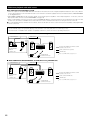
Setting the delay time
• Input the distance between the listening position and the different speakers to set the delay time for the surround mode.
• The delay time can be set separately for surround speakers A and B.
Preparations:
Measure the distances between the listening position and the speakers (L1 to L5 on the diagram at
the right).
L1: Distance between center speaker and listening position
L2: Distance between front speakers and listening position
L3: Distance between surround speakers and listening position
L4: Distance between surround back speakers and listening position
L5: Distance between subwoofer and listening position
FL
Subwoofer
L1
FR
L2
Listening position
L5
L3
SL
SBL
1
Center
L4
SR
SBR
At the System Setup Menu select “Delay Time”.
TUNING
BAND
MODE
TUNING
2
Switch to the Delay Time screen.
ENTER
SHIFT
3
Select the desired unit, meters or feet.
Select (darken) the desired units, “Meters” or “Feet”.
TUNING
BAND
MODE
TUNING
Example: When “Feet” is selected
4
Once “Meters” or “Feet” is selected in step 3, the
Delay Time screen appears automatically.
5
Select the speaker to be set.
TUNING
BAND
MODE
TUNING
22
6
TUNING
BAND
MODE
TUNING
Set the distance between the
center speaker and listening
position.
The distance changes in units of 1
foot (0.1 meters) each time the
button is pressed. Select the value
closest to the measured distance.
Example: When the distance is set to 12 feet
for the center speaker
If “Yes” is selected for “Default”, the settings are automatically reset
to the default values.
Please note that the difference of distance for every speaker should be 15
ft (4.5 m) or less. If you set an invalid distance, a CAUTION notice, such as
screen right will appear. In this case, please relocate the blinking speaker(s)
so that its distance is no larger than the value shown in highlighted line.
7
Enter the setting.
The System Setup Menu reappears.
The AVR-3802 automatically sets the optimum surround delay time for the listening room.
ENTER
SHIFT
NOTE:
• If the distance unit is changed after the delay time is set, the settings are reset to the factory default values (see page 16).
Setting the channel level
•
•
•
•
Use this setting to adjust so that the playback level between the different channels is equal.
From the listening position, listen to the test tones produced from the speakers to adjust the level.
The level can also be adjusted directly from the remote control unit. (For details, see page 49.)
When using both surround speakers A and B, their playback levels can be adjusted separately.
1
At the System Setup Menu select “Channel Level”.
TUNING
BAND
MODE
TUNING
2
Switch to the Channel Level screen.
ENTER
SHIFT
3
Select “Test Tone Mode”.
TUNING
BAND
MODE
TUNING
23
4
TUNING
BAND
MODE
TUNING
Select the mode.
Select “Auto” or “Manual”.
• Auto:
Adjust the level while listening to the test tones produced automatically
from the different speakers.
• Manual:
Select the speaker from which you want to produce the test tone to
adjust the level.
Example: When the “Auto” mode is selected
5
TUNING
BAND
TUNING
MODE
BAND
TUNING
MODE
TUNING
Select “Surr. Sp.”, then select the surround speaker(s) from which you want to produce the test tone (A, B or
A+B).
• Surr. Sp.: A
Adjusts the balance of the playback level between the channels when using surround speaker A.
• Surr. Sp.: B
Adjusts the balance of the playback level between the channels when using surround speaker B.
• Surr. Sp.: A+B
Adjusts the balance of the playback level between the channels when using surround speakers A and B at
the same time.
The “Surr. Sp.” can only be selected when both surround speakers A and B have been selected at the
System Setup Menu (when both A and B have been set to “Large” or “Small”).
Select “Test Tone Start”.
6
TUNING
BAND
MODE
TUNING
7
Select “Yes”.
TUNING
BAND
MODE
TUNING
8
a. If the “Auto” mode is selected:
Test tones are automatically emitted from the different speakers.
The test tones are emitted from the different speakers in the
following order, at 4-second intervals the first time and second time
around, 2-second intervals the third time around and on:
1spkr
SB
FL
C
FR
SR
SBR
SBL
SL
SW
Flashing
2spkrs
Example: When the volume is set to –12 dB
while the test tone is being
produced from the subwoofer
When the surround back speaker setting is set to “1spkr” for
“Speaker Configuration”, this is set to “SB”.
TUNING
BAND
MODE
TUNING
TUNING
BAND
MODE
TUNING
Use the CURSOR buttons to adjust all the speakers to the same
volume.
The volume can be adjusted between –12 dB and +12 dB in units of
1 dB.
b. When the “Manual” mode is selected
Use the CURSOR left and right to select the speaker for which you
want to output test tones, then use the CURSOR up and down to
adjust so that the volume of the test tones from the various speakers
is the same.
Flashing
TUNING
BAND
MODE
TUNING
24
Example: When the volume is set to –12 dB
while the subwoofer is selected
9
After the above settings are completed, press the ENTER button.
The “Channel Level” screen reappears.
ENTER
SHIFT
To cancel the settings, select “Level Clear” and “Yes” on the “Channel Level” screen, then make the settings again.
The level of each channel should be adjusted to 75 dB (C-weighted, slow meter mode) on a sound level meter at the listening position.
If a sound level meter is not available adjust the channels by ear so the sound levels are the same. Because adjusting the subwoofer level test
tone by ear is difficult, use a well known music selection and adjust for natural balance.
NOTE:
When adjusting the level of an active subwoofer system, you may also need to adjust the subwoofer’s own volume control.
When you adjust the channel levels while in the SYSTEM SETUP CHANNEL LEVEL mode, the channel level adjustments made will affect
all surround modes. Consider this mode a Master Channel Level adjustment mode.
After you have completed the SYSTEM SETUP CHANNEL LEVEL adjustments, you can then activate the individual surround modes and
adjust channel levels that will be remembered for each of those modes. Then, whenever you activate a particular surround sound mode,
your preferred channel level adjustments for just that mode will be recalled. Check the instructions for adjusting channel levels within each
surround mode on page 49.
You can adjust the channel levels for each of the following surround modes: DIRECT, STEREO, 5/7 CH STEREO, DOLBY/DTS SURROUND,
WIDE SCREEN, ROCK ARENA, JAZZ CLUB, VIDEO GAME, MONO MOVIE, and MATRIX.
When using either surround speakers A or B, or when using surround speakers A and B at the same time, be sure to adjust the balance of
playback levels between each channel for the various selections of “A or B” and “A and B”.
Setting the Digital In Assignment
• This setting assigns the digital input jacks of the AVR-3802 for the different input sources.
1
At the System Setup Menu select “Digital In Assignment”.
TUNING
BAND
MODE
TUNING
2
SHIFT
3
TUNING
BAND
TUNING
MODE
TUNING
4
Switch to the Digital Inputs screen.
ENTER
ENTER
BAND
MODE
TUNING
Select the digital input jack to be assigned to the input source.
• To select the input source
• To select the digital input jack
Select “OFF” for input sources for which no digital input jacks are used.
If “Yes” is selected for “Default”, the settings are automatically reset to the default values.
Enter the setting.
The System Setup Menu reappears.
SHIFT
NOTES:
• The OPTICAL 3 jacks on the AVR-3802’s rear panel are equipped with an optical digital output jack for recording digital signals on a CD
recorder, MD recorder or other digital recorder. Use this for digital recording between a digital audio source (stereo - 2 channel) and a digital
audio recorder.
• Do not connect the output of the component connected to the OPTICAL 3 OUT jack on the AVR-3802’s rear panel to any jack other than the
OPTICAL 3 IN jack.
• “PHONO” and “TUNER” cannot be selected on the Digital In Assignment screen.
25
Setting the multi vol. level
Set the multi pre-out output level adjustment.
1
ENTER
TUNING
At the “System Setup Menu” screen, select “Multi
Vol. Level” and press the ENTER button.
SHIFT
BAND
MODE
TUNING
2
Select the desired settimg.
TUNING
BAND
MODE
TUNING
0 dB, -40 dB:
The output level is fixed at the set level and the volume can no longer be
adjusted.
Variable:
The level can be adjusted freely using the buttons on the remote control
unit.
3
Enter the setting.
The “System Setup Menu” reappears.
ENTER
SHIFT
Setting the on-screen display (OSD)
• Use this to turn the on-screen display (messages other than the menu screens) on or off.
1
At the System Setup Menu select “On Screen Display”.
TUNING
BAND
MODE
TUNING
2
SHIFT
3
Select “ON” or “OFF”.
TUNING
BAND
MODE
TUNING
26
Switch to the On Screen Display screen.
ENTER
4
Enter the setting.
The System Setup Menu reappears.
ENTER
SHIFT
Auto tuner presets
Use this to automatically search for FM broadcasts and store up to 40 stations at preset channels A1 to 8, B1 to 8, C1 to 8, D1 to 8 and E1 to 8.
NOTE:
• If an FM station cannot be preset automatically due to poor reception, use the “Manual tuning” operation to tune in the station, then preset it
using the manual “Preset memory” operation.
1
Use the CURSOR buttons to specify “Auto Tuner Presets” from the
“System Setup Menu” screen.
TUNING
BAND
MODE
TUNING
2
Press the ENTER button.
The “Auto Preset Memory” screen appears.
ENTER
SHIFT
3
TUNING
BAND
MODE
Use the CURSOR button to select “Yes”.
“Search” flashes on the screen and searching begins.
“Completed” appears once searching is completed.
The display automatically switches to screen.
TUNING
This completes system setup. Once these settings are made, there is no need to change them unless different AV components are connected
or the speakers are repositioned.
27
After completing system setup
This button can be pressed at any time during the system setup process to complete the process.
1
At the System Setup Menu, press the SYSTEM SETUP button.
The changed settings are entered and the on-screen display turns off.
SETUP
• On-screen display signals
Signals input to the AVR-3802
On-screen display signal output
VIDEO signal input jack (yellow)
S-video signal input jack
VIDEO MONITOR OUT video
signal output jack (yellow)
S-video MONITOR OUT video
signal output jack
1
E
E
C
C
2
C
E
C
E
3
E
C
E
C
4
C
C
E
C
(C: Signal
E: No signal)
(C: On-screen signals output
E: On-screen signals not output)
NOTES:
• The on-screen display signals are not output from the color difference (component) video signal MONITOR OUT jacks.
• For 4 above, the on-screen display signals are output to the VIDEO MONITOR OUT video signal output jack (yellow) if the monitor TV is not
connected to the S-video MONITOR OUT video signal output jack.
28
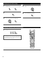
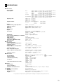
8 REMOTE CONTROL UNIT
• The included remote control unit (RC-883) can be used to operate not only the AVR-3802 but other remote control compatible DENON
components as well. In addition, the memory contains the control signals for other remote control units, so it can be used to operate non-Denon
remote control compatible products.
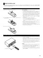
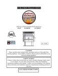
Inserting the batteries
q Remove the remote control unit’s rear cover.
w Set three R6P/AA batteries in the battery compartment in the
indicated direction.
Notes on Batteries
• Use R6P/AA batteries in the remote control unit.
• The batteries should be replaced with new ones approximately
once a year, though this depends on the frequency of usage.
• Even if less than a year has passed, replace the batteries with new
ones if the set does not operate even when the remote control unit
is operated nearby the set. (The included battery is only for verifying
operation. Replace it with a new battery as soon as possible.)
• When inserting the batteries, be sure to do so in the proper
direction, following the “≈” and “√” marks in the battery
compartment.
• To prevent damage or leakage of battery fluid:
• Do not use a new battery together with an old one.
• Do not use two different types of batteries.
• Do not short-circuit, disassemble, heat or dispose of batteries in
flames.
• Remove the batteries from the remote control unit when you do
not plan to use it for an extended period of time.
• If the battery fluid should leak, carefully wipe the fluid off the inside
of the battery compartment and insert new batteries.
• When replacing the batteries, have the new batteries ready and
insert them as quickly as possible.
e Put the rear cover back on.
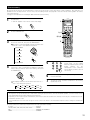
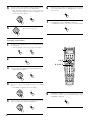
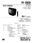
Using the remote control unit
• Point the remote control unit at the remote sensor on the main unit
as shown on the diagram.
• The remote control unit can be used from a straight distance of
approximately 23 feet/7 meters from the main unit, but this
distance will be shorter if there are obstacles in the way or if the
remote control unit is not pointed directly at the remote sensor.
• The remote control unit can be operated at a horizontal angle of up
to 30 degrees with respect to the remote sensor.
B
30°
30°
23 feet/Approx. 7 m
NOTES:
• It may be difficult to operate the remote control unit if the remote
sensor is exposed to direct sunlight or strong artificial light.
• Do not press buttons on the main unit and remote control unit
simultaneously. Doing so may result in malfunction.
• Neon signs or other devices emitting pulse-type noise nearby may
result in malfunction, so keep the set as far away from such
devices as possible.
29
Operating DENON audio components
1
Use the mode selector buttons to select the component you
want to operate.
The mode switches between “AMP”, “TUNER” and
“MULTI” each time the RECEIVER button is pressed,
between “CDR”, “MD” and “TAPE” each time the
CDR/MD/TAPE button is pressed, between “DBS” and
“CABLE” each time the DBS/CABLE button is pressed,
and between “DVD” and “DVD SETUP” each time the
DVD button is pressed, and between “VCR” and “VCR2”
each time the VCR button is pressed.
POWER
ON /
SOURCE
OFF
RC-883
REMOTE CONTROL UNIT
1
TV
CD
VCR
DBS/CABLE
CDR/MD/ TAPE RECEIVER
VDP
MENU
SURR.
PARA.
OSD
SETUP
RETURN
TUNING
A/B
MEMORY
BAND
MODE
CHANNEL
VOLUME
TUNING
+
2
DVD
DISPLAY
Operate the audio component.
• For details, refer to the component’s operating instructions.
It may not be possible to operate some models.
SKIP
ENTER
+
-
SHIFT
SKIP
MUTING
TUNER
PHONO
1
2
3
CDR/ TAPE
VDP
DVD
4
5
6
VCR-1
VCR-2 /V.AUX
TV/DBS
7
8
9
TV/
VCR
0
+10
TEST
TONE
SPEAKER
CD
OUTPUT
SURROUND
DSP
SIMU.
5CH / 7CH
STEREO
6.1 / 7.1
SURROUND
DIRECT
STEREO
MODE
ANALOG
DOLBY/DTS
SURROUND
1. CD player (CD) system buttons
2. Tape deck (TAPE) system buttons
INPUT
EXT.IN
SYSTEM CALL
SETUP
SETUP
RETURN
TUNING
RETURN
TUNING
A/B
A/B
MEMORY
BAND
CHANNEL
:
:
1
:
8, 9 :
3
:
SKIP +, – :
0~9, +10 :
VOLUME
TUNING
+
+
ENTER
MODE
CHANNEL
TUNING
+
2
BAND
VOLUME
SKIP
6, 7
MEMORY
MODE
SKIP
+
ENTER
-
SHIFT
-
MUTING
-
SHIFT
SKIP
SKIP
MUTING
-
TUNER
PHONO
CD
TUNER
PHONO
CD
1
2
3
1
2
3
CDR/TAPE
VDP
DVD
CDR/TAPE
VDP
DVD
4
5
6
4
5
6
VCR-1
VCR-2/V.AUX
TV/DBS
VCR-1
VCR-2/V.AUX
TV/DBS
7
8
9
7
8
9
TV/
VCR
0
+10
TV/
VCR
0
+10
Manual search (forward and reverse)
Stop
Play
Auto search (to beginning of track)
Pause
(for CD changers only)
10 key
3. MD recorder (MD), CD recorder (CDR) system buttons
SETUP
:
:
2
:
1 :
3
:
8 :
A/B :
6
7
Rewind
Fast forward
Stop
Forward play
Pause
Reverse play
Switch between sides A and B
4. Tuner system buttons
SETUP
RETURN
TUNING
RETURN
TUNING
A/B
A/B
MEMORY
BAND
CHANNEL
+
SKIP
6, 7
:
:
1
:
8, 9 :
3
:
0~9, +10 :
2
30
MEMORY
MODE
BAND
CHANNEL
VOLUME
TUNING
ENTER
MODE
+
+
SKIP
VOLUME
TUNING
ENTER
+
-
SHIFT
-
MUTING
-
SHIFT
SKIP
SKIP
MUTING
-
TUNER
PHONO
CD
TUNER
PHONO
CD
1
2
3
1
2
3
CDR/TAPE
VDP
DVD
CDR/TAPE
VDP
DVD
4
5
6
4
5
6
VCR-1
VCR-2/V.AUX
TV/DBS
VCR-1
VCR-2/V.AUX
TV/DBS
7
8
9
7
8
9
TV/
VCR
0
+10
TV/
VCR
0
+10
Manual search (forward and reverse)
Stop
Play
Auto search (to beginning of track)
Pause
10 key
TUNING D, H
BAND
MODE
MEMORY
SHIFT
CHANNEL +, –
1~8
:
:
:
:
:
:
:
Tuning up/down
Switch between AM and FM bands
Switch between AUTO and MONO
Preset memory
Switch preset channel range
Preset channel up/down
10 key
CALL 1
CALL 2
BACKLIGHT
Preset memory
By using the preset memory, the included remote control unit can be used to control other makes of video equipment. Note that this is not
possible for some models, however. In such cases, use the learning function (see page 34) to store the remote control signals in the remote
control unit’s memory.
See page 37 for instructions on resetting the data stored in the preset memory.
1
Press the power ON/SOURCE button and the OFF button at
the same time.
• “SET UP” appears on the remote control unit’s display.
Press the ENTER button.
RC-883
REMOTE CONTROL UNIT
TV
CD
VCR
DBS/CABLE
CDR/MD/ TAPE RECEIVER
VDP
DVD
DISPLAY
MENU
SURR.
PARA.
OSD
SETUP
RETURN
TUNING
3, 4
ENTER
A/B
MEMORY
BAND
MODE
CHANNEL
VOLUME
TUNING
+
SHIFT
3
ON /
SOURCE
OFF
ON /
SOURCE
OFF
2
POWER
1
2, 3, 4
Use the D and H cursor buttons to display “ENTER CODE” on
the remote control unit, then press the ENTER button.
5
The remote control unit’s display switches as follows each
time the D and H cursor buttons are pressed.
SKIP
ENTER
+
-
SHIFT
SKIP
MUTING
TUNER
PHONO
1
2
3
CDR/ TAPE
VDP
DVD
4
5
6
VCR-1
VCR-2 /V.AUX
TV/DBS
7
8
9
TV/
VCR
0
+10
TEST
TONE
SPEAKER
CD
OUTPUT
SURROUND
ENTER CODE
CODE NO
DSP
SIMU.
5CH / 7CH
STEREO
6.1 / 7.1
SURROUND
DIRECT
STEREO
MODE
ANALOG
DOLBY/DTS
SURROUND
TUNING
INPUT
BAND
MODE
EXT.IN
SYSTEM CALL
TUNING
CALL 1
CALL 2
BACKLIGHT
LEARN
SYS CALL
ENTER
RESET
SHIFT
5
AUTO SEARCH
4
After “SEL MODE” is displayed, the last selected mode is
set. Use the D and H cursor buttons to display the component
whose codes you want to store in the memory, then press
the ENTER button.
1
2
3
4
5
6
7
8
9
0
Referring to the included List of
Preset Codes, use the number
buttons to input the preset code (a
4-digit
number)
for
the
manufacturer of the component
whose signals you want to store in
the memory.
TUNING
ENTER
BAND
MODE
SHIFT
TUNING
The display switches as shown below each time the D
and H cursor buttons are pressed.
TV
CD
DVD
VDP
MD
TAPE
VCR
CABLE
DBS
VCR2
6
“OK” is displayed when the signals are registered and the
mode is terminated.
7
To store the codes of another component in the memory,
repeat steps 1 to 6.
NOTES:
• The signals for the pressed buttons are emitted while setting the preset memory. To avoid accidental operation, cover the remote control
unit’s transmitting window while setting the preset memory.
• Depending on the model and year of manufacture, this function cannot be used for some models, even if they are of makes listed on the
included list of preset codes.
• Some manufacturers use more than one type of remote control code. Refer to the included list of preset codes to change the number and
check.
The preset codes are as follows upon shipment from the factory and after resetting:
TV, VCR ........................................................................HITACHI
CD, MD, TAPE, CDR, VDP, DVD, DVD SETUP............DENON
DBS..............................................................................GENERAL INSTRUMENT
CABLE..........................................................................JERROLD
31
Checking the preset memory settings
1
Press the power ON/SOURCE button and the OFF button at
the same time.
• “SET UP” appears on the remote control unit’s display.
4
Press the D and H cursor buttons to display the registered
preset memory on the remote control unit’s display and
check.
TUNING
ON /
SOURCE
OFF
BAND
MODE
TUNING
2
Press the ENTER button.
5
ENTER
Press the ENTER button to terminate.
ENTER
SHIFT
SHIFT
3
Use the D and H cursor buttons to display “CODE NO” on the
remote control unit, then press the ENTER button.
TUNING
ENTER
BAND
MODE
SHIFT
TUNING
Operating a component stored in the preset memory
1
Press the mode selector button for the component you want
to operate.
POWER
ON /
SOURCE
OFF
RC-883
REMOTE CONTROL UNIT
TV
CD
VCR
DBS/CABLE
CDR/MD/ TAPE RECEIVER
VDP
DVD
1
TV
CD
VCR
DBS/CABLE
CDR/MD/ TAPE RECEIVER
VDP
DVD
MENU
DISPLAY
SURR.
PARA.
OSD
SETUP
NOTE:
• For the DVD player remote control buttons, function names may
differ depending on the make. Compare with the remote control
operation of the various components.
RETURN
TUNING
A/B
MEMORY
BAND
MODE
CHANNEL
VOLUME
TUNING
+
SKIP
ENTER
-
SHIFT
SKIP
MUTING
TUNER
PHONO
+
CD
1
2
3
CDR/ TAPE
VDP
DVD
4
5
6
VCR-1
VCR-2 /V.AUX
TV/DBS
7
8
9
TV/
VCR
0
+10
TEST
TONE
SPEAKER
OUTPUT
SURROUND
DSP
SIMU.
5CH / 7CH
STEREO
6.1 / 7.1
SURROUND
DIRECT
STEREO
MODE
ANALOG
DOLBY/DTS
SURROUND
INPUT
EXT.IN
SYSTEM CALL
CALL 1
32
CALL 2
BACKLIGHT
2
Operate the component.
• For details, refer to the component’s operating instructions.
Some models cannot be operated with this remote control unit.
1. Digital video disc player (DVD,
DVD SETUP) system buttons
POWER : Power on/standby
(ON/SOURCE)
6,7 : Manual search
(forward and reverse)
2
: Stop
1
: Play
8,9 : Auto search
(to beginning of track)
3
: Pause
0 ~ 9, +10 : 10 key
skip +, – : Disc skip
(for DVD changer only)
DISPLAY : Display
MENU : Menu
RETURN : Return
SETUP : Setup
POWER
ON /
SOURCE
OFF
RC-883
REMOTE CONTROL UNIT
TV
CDR/MD/ TAPE RECEIVER
CD
VCR
DBS/CABLE
VDP
DVD
DISPLAY
MENU
SURR.
PARA.
OSD
SETUP
2. Video disc player (VDP) system
buttons
POWER
: Power on/standby
(ON/SOURCE)
6,7
: Manual search
(forward and reverse)
2
: Stop
1
: Play
8,9
: Auto search (cue)
3
: Pause
0~9, +10
: 10 key
ON /
SOURCE
RC-883
REMOTE CONTROL UNIT
TV
CD
VCR
DBS/CABLE
VDP
DVD
MENU
DISPLAY
SURR.
PARA.
OSD
RETURN
TUNING
A/B
A/B
MEMORY
BAND
MEMORY
MODE
BAND
CHANNEL
TUNING
+
SKIP
-
SHIFT
SKIP
MUTING
-
TUNER
PHONO
CD
VOLUME
TUNING
+
+
ENTER
MODE
CHANNEL
VOLUME
SKIP
+
ENTER
-
SHIFT
SKIP
MUTING
TUNER
PHONO
CD
1
2
3
1
2
3
CDR/ TAPE
VDP
DVD
CDR/ TAPE
VDP
DVD
4
5
6
4
5
6
VCR-1
VCR-2 /V.AUX
TV/DBS
VCR-1
VCR-2 /V.AUX
TV/DBS
7
8
9
7
8
9
TV/
VCR
0
+10
TV/
VCR
0
+10
TEST
TONE
SPEAKER
TEST
TONE
OUTPUT
SPEAKER
SURROUND
OUTPUT
SURROUND
DOLBY/DTS
SURROUND
DSP
SIMU.
5CH / 7CH
STEREO
DOLBY/DTS
SURROUND
DSP
SIMU.
5CH / 7CH
STEREO
6.1 / 7.1
SURROUND
DIRECT
STEREO
6.1 / 7.1
SURROUND
DIRECT
STEREO
INPUT
MODE
INPUT
ANALOG
EXT.IN
MODE
SYSTEM CALL
CALL 1
CALL 1
BACKLIGHT
POWER
ON /
SOURCE
OFF
RC-883
REMOTE CONTROL UNIT
TV
CD
VCR
DBS/CABLE
CDR/MD/ TAPE RECEIVER
VDP
DVD
DISPLAY
MENU
SURR.
PARA.
OSD
SETUP
RETURN
TUNING
A/B
MEMORY
BAND
MODE
CHANNEL
VOLUME
TUNING
+
ANALOG
EXT.IN
SYSTEM CALL
CALL 2
3. Video deck (VCR/VCR-2) system
buttons
POWER
: Power on/standby
(ON/SOURCE)
6,7
: Manual search
(forward and reverse)
2
: Stop
1
: Play
3
: Pause
Channel +, – : Channels
CDR/MD/ TAPE RECEIVER
SETUP
RETURN
TUNING
POWER
OFF
SKIP
ENTER
+
4. Monitor TV (TV), digital
broadcast satellite (DBS) tuner
and cable (CABLE) system
buttons
POWER
:
(ON/SOURCE)
SETUP
:
RETURN
:
D, H, F, G
:
ENTER
CHANNEL
+, –
0~9, +10
TV/VCR
CALL 2
BACKLIGHT
POWER
ON /
SOURCE
OFF
RC-883
REMOTE CONTROL UNIT
Power on/standby
Setup
Menu
Cursor up, down, left
and right
: Enter
: Switch channels
TV
CD
VCR
DBS/CABLE
CDR/MD/ TAPE RECEIVER
VDP
DVD
MENU
DISPLAY
SURR.
PARA.
OSD
SETUP
RETURN
TUNING
A/B
MEMORY
: Channels
: Switch between TV
and video player
BAND
MODE
CHANNEL
VOLUME
TUNING
+
SKIP
ENTER
+
-
SHIFT
SKIP
-
MUTING
-
SHIFT
SKIP
MUTING
-
TUNER
PHONO
CD
TUNER
PHONO
CD
1
2
3
1
2
3
CDR/ TAPE
VDP
DVD
CDR/ TAPE
VDP
DVD
4
5
6
4
5
6
VCR-1
VCR-2 /V.AUX
TV/DBS
VCR-1
VCR-2 /V.AUX
TV/DBS
7
8
9
7
8
9
+10
TV/
VCR
TV/
VCR
0
TEST
TONE
SPEAKER
OUTPUT
0
TEST
TONE
SPEAKER
SURROUND
SURROUND
DOLBY/DTS
SURROUND
6.1 / 7.1
SURROUND
DSP
SIMU.
5CH / 7CH
STEREO
DOLBY/DTS
SURROUND
DSP
SIMU.
5CH / 7CH
STEREO
DIRECT
STEREO
6.1 / 7.1
SURROUND
DIRECT
STEREO
INPUT
INPUT
MODE
ANALOG
EXT.IN
CALL 2
MODE
ANALOG
EXT.IN
SYSTEM CALL
SYSTEM CALL
CALL 1
+10
OUTPUT
BACKLIGHT
CALL 1
CALL 2
BACKLIGHT
33
Learning function
If your AV component is not a Denon product or if it cannot be operated using the preset memory, it can be controlled with the included remote
control unit by storing its remote control signals in the remote control unit.
1
Press the power ON/SOURCE button and the OFF button
simultaneously.
• “SET UP” appears on the remote control unit’s display.
POWER
1, 5, 8
ON /
SOURCE
OFF
RC-883
REMOTE CONTROL UNIT
ON /
SOURCE
OFF
TV
CD
VCR
DBS/CABLE
CDR/MD/ TAPE RECEIVER
VDP
DVD
MENU
DISPLAY
SURR.
PARA.
OSD
SETUP
2
Press the ENTER button.
3, 4
A/B
MEMORY
BAND
MODE
CHANNEL
ENTER
VOLUME
TUNING
+
2, 3, 4
SHIFT
3
RETURN
TUNING
Use the D and H cursor buttons to display “LEARN” on the
remote control unit’s display, then press the ENTER button.
• “SEL MODE” is displayed.
SKIP
ENTER
+
-
SHIFT
SKIP
MUTING
TUNER
PHONO
1
2
3
CDR/ TAPE
VDP
DVD
4
5
6
VCR-1
VCR-2 /V.AUX
TV/DBS
7
8
9
TV/
VCR
0
+10
TEST
TONE
SPEAKER
CD
OUTPUT
SURROUND
BAND
DSP
SIMU.
5CH / 7CH
STEREO
6.1 / 7.1
SURROUND
DIRECT
STEREO
MODE
ANALOG
DOLBY/DTS
SURROUND
TUNING
ENTER
MODE
INPUT
SHIFT
EXT.IN
SYSTEM CALL
TUNING
4
CALL 1
BAND
ENTER
MODE
SHIFT
7
“COMPLETE” appears on the remote control unit’s display
and learning is completed.
• “SELECT KEY” is displayed. Other keys can be “learned”
by repeating steps 5 to 7.
8
To cancel the learning mode, press the power ON/SOURCE
button and the OFF button simultaneously again.
Registering is not possible in the receiver mode.
TUNING
Press the button to be “learned” while “SELECT KEY” is
displayed. “NOW LEARN” appears.
• “NOT VALID” is displayed if a button that cannot be
“learned” is pressed.
• To cancel, press the power ON/SOURCE button and the
OFF button simultaneously.
OFF
6
ON /
SOURCE
Point the remote control units directly at each other and press
and hold in the button on the other remote control unit which
you want to “learn”.
Other remote
control unit
34
BACKLIGHT
Use the D and H cursor buttons to select the mode for the
button to be “learned”, then press the ENTER button.
• “SELECT KEY” is displayed.
TUNING
5
CALL 2
OFF
ON /
SOURCE
System call
The included remote control unit is equipped with a system call function allowing a series of remote control signals to be transmitted by pressing
a single button.
This function can be used for example to turn on the amplifier’s power, select the input source, turn on the monitor TV’s power, turn on the source
component’s power and set the source to the play mode, all at the touch of a button.
(1) System call buttons
The buttons that can be used for the system call function are
shown on the diagram at the right.
System call signals can be stored at different buttons according to
the mode. System call signals can be stored at a maximum of 6
buttons other than the CALL 1 and CALL 2 buttons.
29 successive operations can be set at each of these buttons.
POWER
ON /
SOURCE
OFF
RC-883
REMOTE CONTROL UNIT
TV
CD
VCR
DBS/CABLE
CDR/MD/ TAPE RECEIVER
VDP
DISPLAY
SURR.
PARA.
(2) Storing system call signals
DVD
MENU
OSD
SETUP
RETURN
TUNING
A/B
MEMORY
1
Press the power ON/SOURCE button and the OFF button at
the same time. “SET UP” appears on the remote control
unit’s display.
ON /
SOURCE
OFF
2
Press the ENTER button.
BAND
VOLUME
TUNING
+
SKIP
+
ENTER
-
SHIFT
SKIP
MUTING
-
TUNER
PHONO
CD
1
2
3
CDR/ TAPE
VDP
DVD
4
5
6
VCR-1
VCR-2 /V.AUX
TV/DBS
7
8
9
TV/
VCR
0
+10
TEST
TONE
ENTER
MODE
CHANNEL
SPEAKER
OUTPUT
SURROUND
SHIFT
DOLBY/DTS
SURROUND
DSP
SIMU.
5CH / 7CH
STEREO
6.1 / 7.1
SURROUND
DIRECT
STEREO
INPUT
MODE
3
Use the D and H cursor buttons to display “SYS CALL” on the
remote control unit, then press the ENTER button.
• Display “SYS MODE” on the remote control unit’s display.
ANALOG
EXT.IN
SYSTEM CALL
CALL 1
CALL 2
BACKLIGHT
TUNING
ENTER
POWER
BAND
MODE
1
SHIFT
ON /
SOURCE
OFF
RC-883
REMOTE CONTROL UNIT
TUNING
4
When “SYS MODE” is displayed, the remote control unit’s
display switches as shown below each time the D and H
cursor buttons are pressed.
7
TV
CD
VCR
DBS/CABLE
CDR/MD/ TAPE RECEIVER
VDP
SURR.
PARA.
OSD
SETUP
RETURN
TUNING
3, 4, 5
A/B
MEMORY
BAND
MODE
CHANNEL
VOLUME
TUNING
SYS MODE
BAND
MODE
SYS CALL 1
SYS CALL 2
TUNING
When “SYS CALL 1” or “SYS CALL 2” is selected, the
signals are stored at the SYSTEM CALL 1 and CALL 2 buttons
(green), regardless of the mode. When the enter button is
pressed, the button registering mode (step 6) is set.
To register at other buttons, select “SYS MODE” then press
the enter button.
• After “SEL MODE” is displayed on the remote control
unit’s display, the mode last set is displayed.
DVD
MENU
DISPLAY
TUNING
+
2, 3, 5, 6, 8
SKIP
ENTER
+
-
SHIFT
SKIP
MUTING
TUNER
PHONO
1
2
3
CDR/ TAPE
VDP
DVD
4
5
6
VCR-1
VCR-2 /V.AUX
TV/DBS
7
8
9
TV/
VCR
0
+10
TEST
TONE
SPEAKER
CD
OUTPUT
SURROUND
DSP
SIMU.
5CH / 7CH
STEREO
6.1 / 7.1
SURROUND
DIRECT
STEREO
MODE
ANALOG
DOLBY/DTS
SURROUND
INPUT
EXT.IN
SYSTEM CALL
CALL 1
CALL 2
BACKLIGHT
35
5
Use the D and H cursor buttons to select the mode for the
button at which the system call signals are to be registered,
then press the ENTER button.
7
q Press the mode selector button according to the button
with the remote control signals to be registered.
TV
CD
VCR
DBS/CABLE
CDR/MD/ TAPE RECEIVER
TUNING
ENTER
BAND
MODE
VDP
DVD
SHIFT
TUNING
w Press the buttons with the remote control signals to be
registered one at a time.
6
“SELECT KEY” is displayed. Press the button at which the
system call signals are to be registered, then press the
ENTER button.
• “ENTER KEYS” is displayed, then the mode display
appears.
8
Press the ENTER button.
• “COMPLETE” appears on the remote control unit’s display
and registration is completed.
ENTER
ENTER
SHIFT
SHIFT
NOTES:
• The remote control signals of the buttons pressed while registering the system call signals are emitted, so be careful not to operate the
components accidentally (cover the remote sensors, for example).
• If you exceed the number of signals that can be registered, “FULL” appears on the remote control unit’s display and only the number of
signals that can be registered are registered (up to 29 operations).
(3) Using the system call function
1
Press the button at which the system call signals have been stored.
• The stored signals are transmitted successively.
Resetting
(1) Resetting the system call buttons
1
Press the power ON/SOURCE button and the OFF button at
the same time.
• “SET UP” appears on the remote control unit’s display.
POWER
1
ON /
SOURCE
OFF
RC-883
REMOTE CONTROL UNIT
ON /
SOURCE
OFF
TV
CD
VCR
DBS/CABLE
CDR/MD/ TAPE RECEIVER
VDP
2
Press the ENTER button.
SURR.
PARA.
OSD
SETUP
RETURN
TUNING
3, 4, 5
ENTER
A/B
MEMORY
BAND
MODE
CHANNEL
VOLUME
TUNING
+
SHIFT
3
DVD
MENU
DISPLAY
2, 3, 4, 5, 6
Use the D and H cursor buttons to display “RESET” on the
remote control unit, then press the ENTER button.
TUNING
ENTER
+
SKIP
ENTER
-
SHIFT
SKIP
MUTING
TUNER
PHONO
1
2
3
CDR/ TAPE
VDP
DVD
4
5
6
VCR-1
VCR-2 /V.AUX
TV/DBS
7
8
9
TV/
VCR
0
+10
TEST
TONE
SPEAKER
CD
OUTPUT
SURROUND
DSP
SIMU.
5CH / 7CH
STEREO
6.1 / 7.1
SURROUND
DIRECT
STEREO
MODE
ANALOG
DOLBY/DTS
SURROUND
BAND
MODE
SHIFT
INPUT
TUNING
EXT.IN
SYSTEM CALL
CALL 1
36
CALL 2
BACKLIGHT
4
q To reset CALL 1 or CALL 2, select “SYS CALL 1” or SYS
CALL 2”, then press the ENTER button.
Use the D and H cursor buttons to display “RESET SYS” on
the remote control unit, then press the ENTER button.
• “SYS SEL” appears on the remote control unit’s display.
ENTER
TUNING
ENTER
SHIFT
BAND
MODE
SHIFT
TUNING
w To reset system call settings registered at other buttons,
select “SYS MODE”, press the ENTER button, press the
mode button at which the button is registered, then press
the ENTER button again.
The remote control unit’s display switches as shown
below each time the D and H cursor buttons are pressed.
RESET PRE
RESET LRN
RESET ALL
RESET SYS
ENTER
SHIFT
5
Press the D and H cursor buttons to select the system call
setting to be reset.
6
TUNING
BAND
MODE
“CONFIRM” is displayed. To reset the setting, press the
ENTER button while “CONFIRM” is displayed.
• “SYS SEL” appears on the remote control unit’s display.
ENTER
TUNING
SHIFT
The remote control unit’s display switches as shown
below each time the D and H cursor buttons are pressed.
SYS MODE
SYS CALL 1
SYS CALL 2
(2) Resetting the preset memory
1
Press the power ON/SOURCE button and the OFF button at
the same time.
• “SET UP” appears on the remote control unit’s display.
POWER
1
ON /
SOURCE
OFF
RC-883
REMOTE CONTROL UNIT
ON /
SOURCE
OFF
TV
CD
VCR
DBS/CABLE
CDR/MD/ TAPE RECEIVER
VDP
2
Press the ENTER button.
SURR.
PARA.
OSD
SETUP
RETURN
TUNING
3, 4, 5
ENTER
A/B
MEMORY
BAND
MODE
CHANNEL
VOLUME
TUNING
+
SHIFT
3
DVD
MENU
DISPLAY
2, 3, 4, 6, 7
Use the D and H cursor buttons to display “RESET” on the
remote control unit, then press the ENTER button.
TUNING
ENTER
+
SKIP
ENTER
-
SHIFT
SKIP
MUTING
TUNER
PHONO
1
2
3
CDR/ TAPE
VDP
DVD
4
5
6
VCR-1
VCR-2 /V.AUX
TV/DBS
7
8
9
TV/
VCR
0
+10
TEST
TONE
SPEAKER
CD
OUTPUT
SURROUND
DSP
SIMU.
5CH / 7CH
STEREO
6.1 / 7.1
SURROUND
DIRECT
STEREO
MODE
ANALOG
DOLBY/DTS
SURROUND
BAND
MODE
SHIFT
INPUT
TUNING
EXT.IN
SYSTEM CALL
CALL 1
CALL 2
BACKLIGHT
37
4
Use the D and H cursor buttons to display “RESET PRE” on
the remote control unit, then press the ENTER button.
• After “SEL PRE” is displayed on the remote control unit’s
display, the registered preset memory is displayed on the
remote control unit’s display.
6
When the mode you want to reset is shown on the remote
control unit’s display, press the ENTER button to reset the
preset memory.
ENTER
SHIFT
TUNING
ENTER
BAND
MODE
SHIFT
7
TUNING
5
“CONFIRM” is displayed. To reset the preset memory, press
the ENTER button while “CONFIRM” is displayed.
• “COMPLETE” appears on the remote control unit’s display.
Use the D and H cursor buttons to
select the code to be reset.
TUNING
ENTER
SHIFT
BAND
MODE
TUNING
(3) Resetting “learned” buttons
1
Press the power ON/SOURCE button and the OFF button at
the same time.
• “SET UP” appears on the remote control unit’s display.
POWER
1
RC-883
REMOTE CONTROL UNIT
ON /
SOURCE
OFF
2
ON /
SOURCE
OFF
TV
CD
VCR
DBS/CABLE
Press the ENTER button.
VDP
DVD
MENU
DISPLAY
SURR.
PARA.
OSD
SETUP
RETURN
TUNING
ENTER
3, 4, 5
A/B
MEMORY
BAND
MODE
CHANNEL
SHIFT
VOLUME
TUNING
+
2, 3, 4, 5, 6
3
CDR/MD/ TAPE RECEIVER
Use the D and H cursor buttons to display “RESET” on the
remote control unit’s display, then press the ENTER button.
• “RESET PRE” is displayed.
TUNING
SKIP
ENTER
-
SHIFT
SKIP
MUTING
TUNER
PHONO
+
CD
1
2
3
CDR/ TAPE
VDP
DVD
4
5
6
VCR-1
VCR-2 /V.AUX
TV/DBS
7
8
9
TV/
VCR
0
+10
ENTER
TEST
TONE
BAND
MODE
SPEAKER
OUTPUT
SURROUND
SHIFT
DSP
SIMU.
5CH / 7CH
STEREO
6.1 / 7.1
SURROUND
DIRECT
STEREO
MODE
ANALOG
DOLBY/DTS
SURROUND
TUNING
INPUT
EXT.IN
SYSTEM CALL
CALL 1
4
CALL 2
BACKLIGHT
Use the D and H cursor buttons to display “RESET LRN” on
the remote control unit’s display, then press the ENTER
button.
• “SEL MODE” is displayed, then “TV” appears.
TUNING
ENTER
BAND
MODE
SHIFT
TUNING
6
“CONFIRM” is displayed. To reset the “learned” button for
the selected mode, press the ENTER button while
“CONFIRM” is displayed.
ENTER
5
Use the D and H cursor buttons to select the mode of the
button to be reset, then press the ENTER button.
TUNING
ENTER
BAND
MODE
TUNING
38
SHIFT
SHIFT
(4) All reset function
• This function is for resetting all the settings to the factory defaults.
1
Press the power ON/SOURCE button and the OFF button at
the same time. “SET UP” appears on the remote control
unit’s display.
POWER
1
ON /
SOURCE
OFF
ON /
SOURCE
OFF
RC-883
REMOTE CONTROL UNIT
TV
CD
VCR
DBS/CABLE
CDR/MD/ TAPE RECEIVER
VDP
DVD
MENU
DISPLAY
SURR.
PARA.
OSD
SETUP
RETURN
TUNING
2
3, 4
Press the ENTER button.
MODE
CHANNEL
VOLUME
TUNING
+
2, 3, 4, 5
ENTER
SHIFT
3
A/B
MEMORY
BAND
Use the D and H cursor buttons to display “RESET” on the
remote control unit, then press the ENTER button.
ENTER
-
SHIFT
SKIP
MUTING
TUNER
PHONO
1
2
3
CDR/ TAPE
VDP
DVD
4
5
6
VCR-1
VCR-2 /V.AUX
TV/DBS
7
8
9
TV/
VCR
0
+10
TEST
TONE
SPEAKER
ENTER
CD
OUTPUT
SURROUND
DSP
SIMU.
5CH / 7CH
STEREO
6.1 / 7.1
SURROUND
DIRECT
STEREO
MODE
ANALOG
DOLBY/DTS
SURROUND
TUNING
+
SKIP
INPUT
BAND
MODE
SHIFT
EXT.IN
SYSTEM CALL
CALL 1
CALL 2
BACKLIGHT
TUNING
4
Use the D and H cursor buttons to display “RESET ALL” on
the remote control unit, then press the ENTER button.
TUNING
ENTER
BAND
MODE
SHIFT
TUNING
5
“CONFIRM” is displayed. To reset, press the ENTER button
while “CONFIRM” is displayed.
• “BUSY” is displayed during the resetting operation, and
“COMPLETE” is displayed once resetting is completed.
ENTER
SHIFT
39
Auto search function
• The set is equipped with a function for searching for the registration
number if you do not know the preset code (a 4-digit number) when
setting the preset memory.
1
2
For TV, DBS or CABLE components, turn on the component’s
power. For CD, MD, TAPE, DVD, VCR and VDP component’s,
turn on the component’s power and load a disc or tape.
Press the power ON/SOURCE button and the OFF button at
the same time.
• “SET UP” appears on the remote control unit’s display.
POWER
2
6
ON /
SOURCE
OFF
RC-883
REMOTE CONTROL UNIT
TV
CD
VCR
DBS/CABLE
CDR/MD/ TAPE RECEIVER
VDP
SURR.
PARA.
OSD
SETUP
RETURN
TUNING
4, 5
A/B
MEMORY
BAND
MODE
CHANNEL
ON /
SOURCE
OFF
3
Press the ENTER button.
DVD
MENU
DISPLAY
VOLUME
TUNING
+
3, 4, 5, 7
SKIP
ENTER
+
-
SHIFT
SKIP
MUTING
TUNER
PHONO
1
2
3
CDR/ TAPE
VDP
DVD
4
5
6
VCR-1
VCR-2 /V.AUX
TV/DBS
7
8
9
TV/
VCR
0
+10
CD
ENTER
TEST
TONE
SPEAKER
OUTPUT
SURROUND
DSP
SIMU.
5CH / 7CH
STEREO
6.1 / 7.1
SURROUND
DIRECT
STEREO
MODE
ANALOG
DOLBY/DTS
SURROUND
SHIFT
INPUT
EXT.IN
SYSTEM CALL
CALL 1
4
CALL 2
BACKLIGHT
Use the D and H cursor buttons to display “AUTOSEARCH”
on the remote control unit, then press the ENTER button.
TUNING
ENTER
BAND
MODE
SHIFT
TUNING
5
Use the D and H cursor buttons to display the mode of the
component to be searched for on the remote control unit’s
display, then press the ENTER button.
• The registration codes are transmitted in order.
TUNING
BAND
ENTER
SHIFT
MODE
TUNING
6
When the component operates, press the POWER OFF
button.
• The mode and the registered number appear on the remote
control unit’s display.
The channel switches on the TV, DBS or CABLE device and
playback stops on a CD, MD, tape, DVD, VCR or VDP player.
OFF
7
Press the ENTER button.
• “COMPLETE” is displayed on the remote control unit’s
display and the selected code is preset.
ENTER
SHIFT
40
If you press the power OFF button late at step 6, press the D and
H cursor button once to move to the next code or back to the
previous code one step at a time.
D button: Next code
H button: Previous code
Auto search resumes when you move ahead from the code at
which you stopped.
9 OPERATION
Before operating
1
2
Refer to “CONNECTIONS” (pages 6 to 13) and check that all
connections are correct.
B
Select “AMP” using the RECEIVER button.
(only when operating with the remote control unit)
RECEIVER
3
(Remote control unit)
3
Turn on the power.
Press the POWER switch (button).
POWER
ON /
SOURCE
OFF
RC-883
REMOTE CONTROL UNIT
3
ON / STANDBY
ON /
SOURCE
ON/STANDBY
Light
(Main unit)
(Remote control unit)
When pressed, the power turns on and the display lights. The sound
is muted for several seconds, after which the unit operates normally.
When pressed again, the power turns off, the standby mode is set
and the display turns off.
Whenever the ON/STANDBY button is in the STANDBY state, the
apparatus is still connected on AC line voltage. Please be sure to
unplug the cord when you leave home for, say, a vacation.
TV
CD
VCR
DBS/CABLE
CDR/MD/ TAPE RECEIVER
2
DISPLAY
VDP
DVD
MENU
41
Playing the input source
SETUP
1
RETURN
5
TUNING
A/B
MEMORY
BAND
MODE
CHANNEL
VOLUME
B
TUNING
+
SKIP
ENTER
-
2
3
MUTING
-
TUNER
PHONO
CD
1
2
3
CDR/ TAPE
VDP
DVD
SHIFT
4
5
6
VCR-1
VCR-2 /V.AUX
TV/DBS
7
8
9
0
TEST
TONE
1
SPEAKER
+10
SURROUND
Example: CD
DSP
SIMU.
5CH / 7CH
STEREO
6.1 / 7.1
SURROUND
DIRECT
STEREO
MODE
ANALOG
3
INPUT
CD
3
(Main unit)
CALL 1
SOURCE
(Main unit)
Select the input mode.
• Selecting the analog mode
Press the ANALOG button to switch to the analog input.
ANALOG
ANALOG
(Main unit)
(Remote control unit)
• Selecting the external input (EXT. IN) mode
Press the EXT. IN (on the EXT. IN button on the remote
control unit) to switch the external input.
EXT.IN
EXT.IN
(Main unit)
(Remote control unit)
• Selecting the AUTO, PCM and DTS modes
The mode switches as shown below each time the INPUT
MODE button is pressed.
PCM
EXT.IN
2
SYSTEM CALL
(Remote control unit)
To select the input source when REC
MULTI OUT or TUNING PRESET is
selected, press the SOURCE button
then operate the input function
selector.
AUTO
1
OUTPUT
DOLBY/DTS
SURROUND
FUNCTION
2
4
SKIP
TV/
VCR
Select the input source to be played.
+
DTS
MODE
CALL 2
BACKLIGHT
Input mode selection function
Different input modes can be selected for the different input sources.
The selected input modes for the separate input sources are stored in
the memory.
q AUTO (auto mode)
In this mode, the types of signals being input to the digital and
analog input jacks for the selected input source are detected and
the program in the AVR-3802’s surround decoder is selected
automatically upon playback. This mode can be selected for all
input sources other than PHONO and TUNER.
The presence or absence of digital signals is detected, the signals
input to the digital input jacks are identified and decoding and
playback are performed automatically in DTS, Dolby Digital or PCM
(2 channel stereo) format. If no digital signal is being input, the
analog input jacks are selected.
Use this mode to play Dolby Digital signals.
w PCM (exclusive PCM signal playback mode)
Decoding and playback are only performed when PCM signals are
being input.
Note that noise may be generated when using this mode to play
signals other than PCM signals.
e DTS (exclusive DTS signal playback mode)
Decoding and playback are only performed when DTS signals are
being input.
r ANALOG (exclusive analog audio signal playback mode)
The signals input to the analog input jacks are decoded and played.
t EXT. IN (external decoder input jack selection mode)
The signals being input to the external decoder input jacks are
played without passing through the surround circuitry.
NOTE:
• Note that noise will be output when CDs or LDs recorded in DTS
format are played in the “PCM” (exclusive PCM signal playback) or
“ANALOG” (exclusive PCM signal playback) mode. Select the
AUTO or DTS mode when playing signals recorded in DTS from a
laser disc player or CD player.
(Remote control unit)
• Selecting the AUTO mode
Press the AUTO button to switch to the auto mode.
AUTO
(Main unit)
42
Note on playing a source encorded with DTS
• Noise may be generated at the beginning of playback and
while searching during DTS playback in the AUTO mode. If
so, play in the DTS mode.
• Selecting the PCM mode
Press the PCM button to switch to the PCM signal input.
Input mode display
One of these lights, depending on the
input signal.
• In the AUTO mode
PCM
INPUT
AUTO
PCM
DTS
DIGITAL
ANALOG
• In the DIGITAL PCM mode
INPUT
(Main unit)
AUTO
• Selecting the DTS mode
Press the DTS button to switch to the DTS signal input.
PCM
DTS
DIGITAL
• In the DIGITAL DTS mode
INPUT
DTS
AUTO
PCM
DTS
DIGITAL
• In the ANALOG mode
INPUT
AUTO
PCM
(Main unit)
3
DTS
ANALOG
Select the play mode.
Input signal display
Example: Stereo
SURROUND
MODE
SELECT
STEREO
• DOLBY DIGITAL
SIGNAL
DIGITAL
(Main unit)
(Remote control unit)
• DTS
SIGNAL
To select the surround mode while adjusting the surround
parameters, channel volume or tone control, press the
surround mode button then operate the selector.
DIGITAL
• PCM
SIGNAL
SURROUND
MODE
DIGITAL
(Main unit)
4
Start playback on the selected component.
• For operating instructions, refer to the component’s
manual.
5
Adjust the volume.
VOLUME
MASTER VOLUME
+
The DIGITAL indicator lights when digital signals are being input
properly. If the DIGITAL indicator does not light, check whether
the digital input component setup (page 25) and connections are
correct and whether the component’s power is turned on.
NOTE:
• The DIGITAL indicator will light when playing CD-ROMs
containing data other than audio signals, but no sound will be
heard.
The volume level is
displayed on the
master volume level
display.
(Main unit)
(Remote control unit)
The volume can be adjusted within the range of –70 to 0 to 18 dB,
in steps of 1 dB. However, when the channel level is set as
described on page 23 or pages 49 and 50, if the volume for any
channel is set at +1 dB or greater, the volume cannot be adjusted
up to 18 dB. (In this case the maximum volume adjustment range
is “18 dB — (Maximum value of channel level)”.)
Input mode when playing DTS sources
• Noise will be output if DTS-compatible CDs or LDs are played in the
“ANALOG” or “PCM” mode.
When playing DTS-compatible sources, be sure to connect the
source component to the digital input jacks (OPTICAL/COAXIAL)
and set the input mode to “DTS”.
43
Playback using the external input (EXT. IN) jacks
1
Set the external input (EXT.
IN) mode.
Press the EXT. IN to switch
the external input.
EXT.IN
EXT.IN
B
(Main unit)
(Remote control unit)
Once this is selected, the input signals connected to the FL
(front left), FR (front right), C (center), SL (surround left), SR
(surround right), SBL (surround back left) and SBR (surround
back right) channels of the EXT. IN jacks are output directly to
the front (left and right), center, surround (left and right) and
surround back (left and right) speaker systems as well as the
pre-out jacks without passing through the surround circuitry.
In addition, the signal input to the SW (subwoofer) jack is
output to the PRE OUT SUBWOOFER jack.
2
6.1 / 7.1
SURROUND
2
2
Cancelling the external input mode
To cancel the external input (EXT. IN) setting, press the input
mode (AUTO, PCM, DTS) or ANALOG button to switch to the
desired input mode. (See page 42.)
AUTO
PCM
DTS
ANALOG
(Remote control unit)
• When the input mode is set to the external input (EXT. IN), the play
mode (DIRECT, STEREO, DOLBY/DTS SURROUND, 5/7CH
STEREO, WIDE SCREEN or DSP SIMULATION) cannot be set.
44
DIRECT
STEREO
INPUT
MODE
ANALOG
EXT.IN
SYSTEM CALL
CALL 1
CALL 2
1
BACKLIGHT
ANALOG
MODE
(Main unit)
1
NOTES:
• In play modes other than the external input mode, the signals
connected to these jacks cannot be played. In addition, signals
cannot be output from channels not connected to the input
jacks.
• The external input mode can be set for any input source. To
watch video while listening to sound, select the input source to
which the video signal is connected, then set this mode.
After starting playback
[1] Adjusting the sound quality (TONE)
The tone control function will not work in the direct mode.
1
The tone switches as follows each time the TONE CONTROL
button is pressed.
B
TONE
CONTROL
BASS
TREBLE
(Main unit)
2
With the name of the volume to be
adjusted selected, turn the SELECT
knob to adjust the level.
3
SELECT
21
(Main unit)
• To increase the bass or treble: Turn the control clockwise.
(The bass or treble sound can be increased to up to +12 dB
in steps of 2 dB.)
• To decrease the bass or treble: Turn the control clockwise.
(The bass or treble sound can be decreased to up to –12 dB
in steps of 2 dB.)
3
If you do not want the bass and treble to be adjusted, turn on
the tone defeat mode.
TONE DEFEAT
The signals do not pass through the
bass and treble adjustment circuits,
providing higher quality sound.
[2] Listening over headphones
1
Connect the headphones to the
PHONES jack of the front panel.
PHONES
B
1
2
Press the OUTPUT button to play the sound over the
headphones only.
TV/
VCR
0
+10
OUTPUT
TEST
TONE
SPEAKER
OUTPUT
2
1
NOTE:
To prevent hearing loss, do not raise the volume level excessively
when using headphones.
SURROUND
DOLBY/DTS
SURROUND
DSP
SIMU.
5CH / 7CH
STEREO
• The output to the speaker and pre-out jacks is turned off
and no sound is produced from the speakers.
Caution: Switching off the power of the unit and the unit will
cancel the settings.
[3] Turning the sound off temporarily (MUTING)
1
Use this to turn off the audio output
temporarily.
Press the MUTING button.
Cancelling MUTING mode.
Press the MUTING button again.
MUTING
(Remote control unit)
+
TUNING
SKIP
ENTER
+
-
SHIFT
SKIP
MUTING
-
TUNER
PHONO
CD
1
2
3
1
45
[4] Combining the currently playing sound with the desired image
1
Simulcast playback
Use this switch to monitor a video
source other than the audio source.
Press the VIDEO SELECT button
repeatedly until the desired source
appears on the display.
Cancelling simulcast playback.
VIDEO SELECT
B
(Main unit)
• Select “SOURCE” using the VIDEO SELECT button.
• Switch the program source to the component connected to
the video input.
1
[5] Checking the currently playing program source, etc.
1
On screen display
• Each time an operation is performed,
a description of that operation
appears on the display connected to
the unit’s VIDEO MONITOR OUT
jack. Also, the unit’s operating status
can be checked during playback by
pressing the remote control unit’s
OSD button.
Such information as the position of
the input selector and the surround
parameter settings is output in
sequence.
Front panel display
• Descriptions of the unit’s operations
are also displayed on the front panel
display. In addition, the display can be
switched to check the unit’s
operating status while playing a
source by pressing the STATUS
button.
VCR
OSD
DBS/CABLE
VDP
DVD
MENU
DISPLAY
SURR.
PARA.
OSD
SETUP
RETURN
TUNING
1
A/B
MEMORY
BAND
MODE
(Remote control unit)
1
STATUS
(Main unit)
Using the dimmer function
• Use this to change the brightness of the display.
The display brightness changes in four steps
(bright, medium, dim and off) by pressing the
remote control unit’s DIMMER button repeatedly.
The brightness changes in 3 steps each time the
button is pressed, and finally the display turns
off.
DIMMER
(Main unit)
Multi-source recording/playback
[1] Playing one source while recording another (REC OUT mode)
1
Press the REC/MULTI button.
2,4
REC /
MULTI
2
B
(Main unit)
2
With “RECOUT SOURCE” displayed,
turn the FUNCTION knob to select the
source you wish to record.
• The “REC” indicator and the indicator
of the selected source light.
FUNCTION
1
Display
(Main unit)
3
Set the recording mode.
• For operating instructions, refer to the manual of the
component on which you want to record.
4
To cancel, turn the function knob and select “SOURCE”.
• When “SOURCE” is selected, the “REC” indicator turns
off.
FUNCTION
(Main unit)
46
2
REC
PHONO CD TUNER
VCR
-1 -2
RECOUT
DVD /
/
VDP TV / DBS
TAPE -1 -2
SOURCE
NOTES:
• Recording sources other than digital inputs selected in the REC
OUT mode are also output to the multi source audio output
jacks.
• Digital signals are not output from the REC SOURCE or audio
output jacks.
[2] Outputting a program source to an amplifier, etc., in a different room (MULTI mode)
1
Press the REC/MULTI button.
The display switches as follows each
time the button is pressed.
REC /
MULTI
2,4
2
B
(Main unit)
2
With “M-SOURCE SOURCE” displayed,
turn the FUNCTION knob and select the
source you wish to output.
• The “MULTI” indicator and the
indicator of the selected source light.
FUNCTION
1
(Main unit)
3
Start playing the source to be output.
• For operating instructions, refer to the manuals of the
respective components.
4
To cancel, turn the function knob and select “SOURCE”.
• When “SOURCE” is selected, the “MULTI” indicator turns
off.
FUNCTION
2
Display
MULTI
PHONO CD TUNER
VCR
-1 -2
DVD /
/
VDP TV / DBS
TAPE -1 -2
M-SOURCE SOURCE
NOTES:
• The signals of the source selected in the MULTI mode are also
output from the VCR-1, VCR-2/V.AUX and CDR/TAPE recording
output terminals.
• Digital signals are not output from the multi source audio output
jacks.
(Main unit)
[3] Remote control unit operations during multi-source playback (selecting the input source)
This operation is possible when Multi mode is selected.
This operation is not possible in the REC OUT mode.
1
Select “MULTI” using the
RECEIVER button.
RECEIVER
TV
CD
VCR
DBS/CABLE
CDR/MD/ TAPE RECEIVER
1
VDP
DVD
MENU
DISPLAY
SURR.
PARA.
OSD
SETUP
RETURN
TUNING
A/B
(Remote control unit)
MEMORY
BAND
2
Press the input source
Example: CD
button.
The multi source switches
directly.
MODE
CHANNEL
CD
3
VOLUME
TUNING
+
SKIP
-
SHIFT
SKIP
MUTING
TUNER
PHONO
(Remote control unit)
+
ENTER
CD
1
2
3
CDR/ TAPE
VDP
DVD
4
5
6
VCR-1
VCR-2 /V.AUX
TV/DBS
7
8
9
2
[4] Remote control unit operation during multi-source playback (adjusting the volume level)
1
Select “MULTI” using the
RECEIVER button.
RECEIVER
TV
CD
VCR
DBS/CABLE
CDR/MD/ TAPE RECEIVER
1
DVD
MENU
DISPLAY
SURR.
PARA.
(Remote control unit)
VDP
OSD
SETUP
RETURN
TUNING
2
Use the VOLUME buttons to adjust the
volume level.
NOTE:
MULTI VOLUME functions when
“Variable” is selected for SYSTEM
SETUP MENU “Multi Vol. Level”.
(See page 26.)
A/B
MEMORY
VOLUME
BAND
MODE
CHANNEL
+
+
SKIP
-
-
VOLUME
TUNING
ENTER
+
2
SKIP
MUTING
-
TUNER
PHONO
CD
SHIFT
(Remote control unit)
47
Multi-zone playback with multi-source
MULTI ZONE MUSIC ENTERTAINMENT SYSTEM
• When the outputs of the MULTI ZONE PRE OUT terminals are wired and connected to integrated amplifiers installed in other rooms, different
sources can be played in rooms other than the main room in which this unit and the playback devices are installed. (Refer to ANOTHER ROOM
on the diagram below.)
• MULTI ZONE SPEAKER OUT can be used when “Multi” is selected at System Setup Menu “Power Amp Assignment”. In this case, Surround
Back Speaker OUT cannot be used for MAIN ROOM. (See page 18.)
• When a sold separately room-to-room remote control unit (DENON RC-616, 617 or 618) is wired and connected between the main room and
another room, the remote-controllable devices in the main room can be controlled from another room using the remote control unit.
To control playback devices other than the ones above, either use that device’s remote control unit or preset a separately sold programmable
remote control unit.
NOTES:
• For the AUDIO output, use high quality pin-plug cords and wire in such a way that there is no humming or noise.
• For instructions on installation and operation of separately sold devices, refer to the devices’ operating instructions.
2 MULTI ZONE MUSIC ENTERTAINMENT SYSTEM (When using PREOUT)
ANOTHER ROOM
MAIN ROOM
RC-617
B
INTEGRATED
AMPLIFIER
ROOM-TO-ROOM REMOTE CONTROL SYSTEM
(separately sold) control line
PROGRAMMABLE
REMOTE
CONTROL UNIT
AVR-3802
MULTI SOURCE AUDIO signal cable
SPEAKER cable
SYSTEM REMOTE
CONTROL UNIT RC-883
RC-616
* Refer to CONNECTIONS on pages 6 to 13.
2 MULTI ZONE MUSIC ENTERTAINMENT SYSTEM (When using SPEAKER OUT)
ANOTHER ROOM
MAIN ROOM
RC-617
B
ROOM-TO-ROOM REMOTE CONTROL SYSTEM
(separately sold) control line
PROGRAMMABLE
REMOTE
CONTROL UNIT
AVR-3802
SPEAKER cable
RC-616
48
MULTI SOURCE SPEAKER cable
SYSTEM REMOTE
CONTROL UNIT RC-883
* Refer to CONNECTIONS on pages 6 to 13.
10 SURROUND
Before playing with the surround function
• Before playing with the surround function, be sure to use the test tones to adjust the playback level from the different speakers. This adjustment
can be performed with the system setup (see page 23) or from the remote control unit, as described below.
• Adjusting with the remote control unit using the test tones is only possible in the “Auto” mode and only effective in the DOLBY/DTS
SURROUND modes. The adjusted levels for the different modes are automatically stored in the memory.
1
SETUP
Press the TEST TONE button.
RETURN
TUNING
2
TEST
TONE
A/B
MEMORY
BAND
MODE
CHANNEL
+
SKIP
2
TUNING
BAND
MODE
TUNING
TUNING
+
ENTER
-
SHIFT
SKIP
MUTING
-
TUNER
PHONO
CD
1
2
3
CDR/ TAPE
VDP
DVD
4
5
6
VCR-1
VCR-2 /V.AUX
TV/DBS
7
8
9
TV/
VCR
0
+10
(Remote control unit)
Test tones are output from the
different speakers. Use the channel
volume adjust buttons to adjust so
that the volume of the test tones is
the same for all the speakers.
VOLUME
1, 3
TEST
TONE
SPEAKER
OUTPUT
(Remote control unit)
3
After completing the adjustment,
press the TEST TONE button again.
TEST
TONE
(Remote control unit)
• After adjusting using the test tones, adjust the channel levels either according to the playback sources or to suit your tastes, as described below.
1
Select the speaker whose level you want to adjust.
CH VOL
ENTER
B
SHIFT
(Main unit)
(Remote control unit)
The channel switches as shown below each time the button
is pressed.
FL
C
FADER
FR
SR
SBR
SW
2 1
SBL
SL
SETUP
RETURN
TUNING
2
2
Adjust the level of the selected speaker.
MEMORY
BAND
MODE
CHANNEL
TUNING
SELECT
BAND
+
MODE
1
A/B
VOLUME
TUNING
+
SKIP
ENTER
-
SHIFT
SKIP
MUTING
-
TUNER
PHONO
CD
TUNING
(Main unit)
(Remote control unit)
When the surround back speaker setting is set to “1spkr” for
“Speaker Configuration”, this is set to “SB”.
NOTES:
• The adjustment range for the different channels is +12 dB to
–12 dB.
• When using the DIRECT mode, the sound from the subwoofer
can be cut by lowering the SW (subwoofer) setting one step
from –12 dB (setting it to “OFF”).
49
Fader function
• This function makes it possible to lower the volume of the front channels (FL, C and FR) or the rear channels (SL, SR, SBL and SBR) together.
Use it for example to adjust the balance of the sound from the different positions when playing multi-channel music sources.
1
Select “FADER”.
B
CH VOL
ENTER
SHIFT
(Main unit)
(Remote control unit)
The channel switches in the order shown below each time
this button is pressed.
FL
C
FR
SR
SBR
2 1
SBL
SETUP
RETURN
TUNING
FADER
SW
2
SL
A/B
MEMORY
BAND
MODE
CHANNEL
2
Press the D button to reduce the volume of the front
channels, the H button to reduce the volume of the rear
channels.
VOLUME
TUNING
+
SKIP
1
+
ENTER
-
SHIFT
SKIP
MUTING
-
TUNER
PHONO
CD
The fader function does not affect the SW channel.
TUNING
SELECT
BAND
MODE
TUNING
(Main unit)
(Remote control unit)
The channel whose channel level is adjusted lowest can be faded
to –12 dB using the fader function.
If the channel levels are adjusted separately after adjusting the
fader, the fader adjustment values are cleared, so adjust the fader
again.
This is only displayed when setting the fader control.
Dolby Surround Pro Logic II mode
B
TV
CD
VCR
3
CDR/MD/ TAPE RECEIVER
DBS/CABLE
VDP
DVD
MENU
DISPLAY
SURR.
PARA.
OSD
SETUP
RETURN
TUNING
A/B
MEMORY
4, 5, 6
1 3, 5 1, 4, 6
1
+
Select the Dolby Surround Pro Logic II mode.
• The Dolby Pro Logic indicator lights.
Light
SURROUND
MODE
BAND
SELECT
DOLBY/DTS
SURROUND
MODE
CHANNEL
VOLUME
TUNING
SKIP
ENTER
+
-
SHIFT
SKIP
MUTING
-
TUNER
PHONO
CD
1
2
3
CDR/ TAPE
VDP
DVD
4
5
6
VCR-1
VCR-2 /V.AUX
TV/DBS
7
8
9
TV/
VCR
0
+10
Display
TEST
TONE
(Main unit)
2
50
(Remote control unit)
Play a program source with the
mark.
• For operating instructions, refer to the manuals of the
respective components.
1
SPEAKER
OUTPUT
SURROUND
DOLBY/DTS
SURROUND
DSP
SIMU.
5CH / 7CH
STEREO
6.1 / 7.1
SURROUND
DIRECT
STEREO
INPUT
3
Set the surround parameter mode.
SURROUND
PARAMETER
SURR.
PARA.
Display
MODE CINEMA
(Main unit)
(Remote control unit)
The on-screen display differs according to whether the operation is performed from the
main unit or the remote control unit.
4
Select the play mode.
TUNING
SELECT
BAND
MODE
TUNING
(Main unit)
(Remote control unit)
Display
MODE CINEMA
5
MODE MUSIC
MODE PRO LOGIC
Select the various parameters. (See “Surround parameters q” for a description of the various parameters.)
SURROUND
PARAMETER
TUNING
BAND
MODE
TUNING
(Main unit)
(Remote control unit)
MODE CINEMA
MODE MUSIC
MODE PRO LOGIC
CINEMA EQ
PANORAMA
CINEMA EQ
DIMENSION
CENTER WIDTH
6
Set the various surround parameters.
SELECT
TUNING
BAND
MODE
TUNING
(Main unit)
7
(Remote control unit)
When the surround parameters are set using the buttons on
the main unit, stop operating buttons after completing the
settings. The settings are automatically finalized and the
normal display reappears after several seconds.
When the settings are made using the buttons on the remote
control unit, press the SURR. PARA. button to finish.
NOTE:
• There are four Dolby Surround Pro Logic modes (NORMAL,
PHANTOM, WIDE and 3CH. LOGIC). The AVR-3802 sets the
mode automatically according to the types of speakers set
during the system setup process (page 18).
When set with the on-screen display using the remote control unit
while in the MUSIC mode, set the “ ” mark to “OPTION 0”
using the D and H cursor buttons, then press the F cursor button.
Press the ENTER button to return to the previous screen.
Surround parameters q
Pro Logic II Mode:
The Cinema mode is the standard required mode for all A/V
systems.
The Music mode is recommended as the standard mode for
autosound music systems (no video), and is optional for A/V
systems.
The Pro Logic mode offers the same robust surround processing
as original Pro Logic in case the source contents is not of optimum
quality.
Select one of the modes (“Cinema”, “Music” or “Pro Logic”).
Panorama Mode:
This mode extends the front stereo image to include the surround
speakers for an exciting “wraparound” effect with side wall
imaging.
Select “OFF” or “ON”.
Dimension Control:
This control gradually adjust the soundfield either towards the front
or towards the rear.
The control can be set in 7 steps from o to 6.
Center Width Control:
This control adjust the center image so it may be heard only from
the center speaker; only from the left/right speakers as a phontom
image; or from all three front speakers to varying degrees.
The control can be set in 8 steps from 0 to 7.
51
Dolby Digital mode (only with digital input) and DTS Surround mode (only with digital input)
1
Select the input source.
Playback with a digital input
q Select an input source set to digital (COAXIAL/OPTICAL)
(see page 25).
1
FUNCTION
VDP
3
5
B
(Main unit)
(Remote control unit)
w Set the input mode to “AUTO” or “DTS”.
AUTO
DTS
MODE
3
(Main unit)
1
2 4,5 2,6
(Remote control unit)
POWER
ON /
SOURCE
OFF
2
Select the Dolby/DTS Surround mode.
RC-883
REMOTE CONTROL UNIT
DOLBY/DTS
SURROUND
TV
CD
VCR
CDR/MD/ TAPE RECEIVER
DBS/CABLE
VDP
DVD
(Remote control unit)
When performing this operation from the main unit’s panel,
press the SURROUND MODE button, then turn the SELECT
knob and select Dolby Pro logic or DTS NEO:6.
SURROUND
MODE
4
SURR.
PARA.
RETURN
TUNING
5, 6
(Main unit)
1
DIGITAL
Light
Light
SIGNAL
DETECT
Light
,
mark.
• The Dolby Digital indicator lights
when playing Dolby Digital sources.
VOLUME
TUNING
• The DTS indicator lights when playing
DTS sources.
• The SIGNAL DETECT LED lights
when playing DTS-ES/6.1-channel
surround sources containing the
identification signal.
Operate the 6.1/7.1 Surround button to switch Surround Back
CH ON/OFF.
(Main unit)
SURROUND
BACK CH
OUTPUT
Light
52
ENTER
-
SHIFT
SKIP
MUTING
TUNER
PHONO
+
CD
1
2
3
CDR/ TAPE
VDP
DVD
4
5
6
VCR-1
VCR-2 /V.AUX
TV/DBS
7
8
9
TV/
VCR
0
+10
TEST
TONE
SPEAKER
OUTPUT
SURROUND
When the SIGNAL DETECT LED is lit, we recommend
turning the surround back channel using the 6.1/7.1
Surround button on the remote control unit and main unit
during playback.
6.1 / 7.1
SURROUND
MODE
CHANNEL
+
Play a program source with the
A/B
MEMORY
BAND
SKIP
3
OSD
SETUP
SELECT
(Main unit)
MENU
DISPLAY
6.1 / 7.1
SURROUND
(Remote control unit)
• Lights when the 6.1/7.1 Surround
mode is on.
2
3
1
DOLBY/DTS
SURROUND
DSP
SIMU.
5CH / 7CH
STEREO
6.1 / 7.1
SURROUND
DIRECT
STEREO
INPUT
MODE
ANALOG
EXT.IN
SYSTEM CALL
CALL 1
CALL 2
BACKLIGHT
4
SURROUND
PARAMETER
(Main unit)
Display the
surround parameter
menu.
SURR.
PARA.
(Remote control unit)
NOTE: The display on the screen differs depending on
whether you are performing the operation from
the main unit or the remote control unit.
5
6
Select the various parameters.
SURROUND
PARAMETER
TUNING
BAND
Adjust the parameter settings.
SELECT
TUNING
MODE
BAND
TUNING
(Main unit)
MODE
TUNING
(Remote control unit)
(Main unit)
(Remote control unit)
2 Dialogue Normalization
The dialogue normalization function is activated automatically when playing Dolby Digital program sources.
Dialogue normalization is a basic function of Dolby Digital which automatically normalizes the dialog level (standard level) of the signals which are
recorded at different levels for different program sources, such as DVD, DTV and other future formats that will use Dolby Digital.
These contents can be verified with the STATUS button.
OFFSET
- 4dB
The number indicates the normalization level when the currently playing program is normalized to the
standard level.
NOTE:
• When “Default” is selected and the F cursor button is pressed, “CINEMA EQ.” and “D.COMP.” are automatically turned off, “LFE” is reset,
and the tone is set to the default value.
Surround parameters w
CINEMA EQ. (Cinema Equalizer):
The Cinema EQ function gently decreases the level of the extreme high frequencies, compensating for overly-bright sounding motion picture
soundtracks. Select this function if the sound from the front speakers is too bright.
This function only works in the Dolby Pro Logic, Dolby Digital, DTS Surround and WIDE SCREEN modes. (The same contents are set for all operating
modes.)
D.COMP. (Dynamic Range Compression):
Motion picture soundtracks have tremendous dynamic range (the contrast between very soft and very loud sounds). For listening late at night, or
whenever the maximum sound level is lower than usual, the Dynamic Range Compression allows you to hear all of the sounds in the soundtrack (but
with reduced dynamic range). (This only works when playing program sources recorded in Dolby Digital or DTS.) Select one of the four parameters
(“OFF”, “LOW”, “MID” (middle) or “HI” (high)). Set to OFF for normal listening.
LFE (Low Frequency Effect):
This sets the level of the LFE (Low Frequency Effect) sounds included in the source when playing program sources recorded in Dolby Digital or DTS.
If the sound produced from the subwoofer sounds distorted due to the LFE signals when playing Dolby Digital or DTS sources when the peak limiter is
turned off with the subwoofer peak limit level setting (system setup menu), adjust the level as necessary.
Program source and adjustment range:
1. Dolby Digital:
–10 dB to 0 dB
2. DTS Surround:
–10 dB to 0 dB
When DTS encoded movie software is played, it is recommended that the LFE LEVEL be set to 0 dB for correct DTS playback.
When DTS encoded music software is played, it is recommended that the LFE LEVEL be set to –10 dB for correct DTS playback.
TONE:
This adjusts the tone control. (See “Surround parameters e” on page 58.)
AFDM (Auto Flag Detect Mode):
Turns the auto flag detect mode on and off. (See page 21.)
For 5-channel Dolby Digital/DTS sources:
The surround back channel play mode can be selected when the AFDM (Auto Flag Detect Mode) is set to “OFF”. The parameters that can be
selected are the same as the “Non-Flag Source SBch Output” settings.
When the AFDM (Auto Flag Detect Mode) is set to “ON”, the setting selected at “Non-Flag Source SBch Output” are displayed. (See page 21.)
If you wish to change the setting, set the AFDM (Auto Flag Detect Mode) to “OFF”.
SB CH OUT (6.1/7.1 Surround):
(1) Dolby Digital/DTS source
“OFF” ....................Playback is conducted without using the surround back speaker.
“NON MTRX”........Playback is conducted using the surround back speaker.
The same signals those of the surround channels are output from the surround back channels.
“MTRX ON” ..........Playback is conducted using the surround back speaker.
Surround back chnnel is reproduced using digital matrix processing.
(2) Other source
“OFF” ....................Playback is conducted without using the surround back speaker.
“ON” .....................Playback is conducted using the surround back speaker.
NOTE: This operation can be performed directly using the “6.1/7.1 Surround” button on the main unit’s panel.
53
11 DSP SURROUND SIMULATION
• The AVR-3802 is equipped with a high performance DSP (Digital Signal Processor) which uses digital signal processing to synthetically recreate
the sound field. One of seven preset surround modes can be selected according to the program source and the parameters can be adjusted
according to the conditions in the listening room to achieve a more realistic, powerful sound. These surround modes can also be used for
program sources not recorded in Dolby Surround Pro Logic or Dolby Digital.
Surround modes and their features
1
WIDE SCREEN
Select this to achieve an atmosphere like that of a movie theater with a large screen. In this mode, all signal
sources are played in the 7.1-channel mode, including Dolby Pro Logic and Dolby Digital 5.1-channel sources.
Effects simulating the multi surround speakers of movie theaters are added to the surround channels.
2
ROCK ARENA
Use this mode to achieve the feeling of a live concert in an arena with reflected sounds coming from all directions.
3
JAZZ CLUB
This mode creates the sound field of a live house with a low ceiling and hard walls. This mode gives jazz a very
vivid realism.
4
VIDEO GAME
Use this to enjoy video game sources.
5
MATRIX
Select this to emphasize the sense of expansion for music sources recorded in stereo. Signals consisting of the
difference component of the input signals (the component that provides the sense of expansion) processed for
delay are output from the surround channel.
6
MONO MOVIE
(NOTE 1)
Select this when watching monaural movies for a greater sense of expansion.
7
5CH/7CH
STEREO
In this mode, the signals of the front left channel are output from the left surround channel, the signals of the front
right channel are output from the right surround channel, and the same (in-phase) component of the left and right
channels is output from the center channel. This mode provides all speaker surround sound, but without directional
steering effects, and works with any stereo program source.
Depending on the program source being played, the effect may not be very noticeable.
In this case, try other surround modes, without worrying about their names, to create a sound field suited to your tastes.
NOTE 1: When playing sources recorded in monaural, the sound will be one-sided if signals are only input to one channel (left or right), so input
signals to both channels. If you have a source component with only one audio output (monophonic camcorder, etc.) obtain a “Y” adaptor
cable to split the mono output to two outputs, and connect to the L and R inputs.
NOTE:
Only the DIRECT and 5CH/7CH STEREO modes can be used when playing PCM signals with a sampling frequency of 96 kHz (such as from
DVD-Video discs that contain 24 bit, 96 kHz audio). If such signals are input during playback in one of the other surround modes, the mode
automatically switches to DIRECT.
Personal Memory Plus
This set is equipped with a personal memorize function that automatically memorizes the surround modes and input modes selected for the
input different sources. When the input source is switched, the modes set for that source last time it was used are automatically recalled.
The surround parameters, tone control settings and playback level balance for the different output channels are memorized for each
surround mode.
54
DSP surround simulation
• To operate the surround mode and surround parameters from the remote control unit.
1
Select the surround mode for the input channel.
C
2, 4
SURROUND
DOLBY/DTS
SURROUND
5CH / 7CH
STEREO
DSP
SIMU.
S/C
MENU
DISPLAY
SURR.
PARA.
OSD
SETUP
RETURN
TUNING
6.1 / 7.1
SURROUND
3
STEREO
DIRECT
A/B
MEMORY
BAND
MODE
CHANNEL
+
(Remote control unit)
SKIP
The surround mode switches in the following order each time
the DSP SIMULATION button is pressed:
WIDE SCREEN
MATRIX
MONO MOVIE
ROCK ARENA
VIDEO GAME
VOLUME
TUNING
ENTER
-
SHIFT
SKIP
MUTING
TUNER
PHONO
+
CD
1
2
3
CDR/ TAPE
VDP
DVD
4
5
6
VCR-1
VCR-2 /V.AUX
TV/DBS
7
8
9
TV/
VCR
0
+10
JAZZ CLUB
TEST
TONE
SPEAKER
OUTPUT
SURROUND
1
2
DOLBY/DTS
SURROUND
DSP
SIMU.
5CH / 7CH
STEREO
6.1 / 7.1
SURROUND
DIRECT
STEREO
Display the surround parameter screen on the monitor.
The screen for the selected surround mode appears.
SURR.
PARA.
(Remote control unit)
3
Set the parameters.
TUNING
BAND
TUNING
MODE
BAND
TUNING
MODE
TUNING
(Remote control unit)
4
To end the setting mode, press the surround parameter button again.
SURR.
PARA.
(Remote control unit)
NOTES:
• The surround speaker setting can also be changed with the SPEAKER button on the remote control unit.
• When “Default” is selected and the F courser button is pressed, “CINEMA EQ.” and “D.COMP.” are automatically turned off, “ROOM
SIZE” is set to “medium”, “EFFECT LEVEL” to “10”, “DELAY TIME” to “30ms” and “LFE” to “0dB”.
• The “ROOM SIZE” expresses the expansion effect for the different surround modes in terms of the size of the sound field, not the actual
size of the listening room.
55
• Operating the surround mode and surround parameters from the main unit‘s panel.
1
Turn the SELECT knob to select the surround mode.
B
SELECT
(Main unit)
1 2
1,3
• When turned clockwise
DIRECT
MATRIX
STEREO
DOLBY PRO LOGIC II
VIDEO GAME
JAZZ CLUB
DTS NEO:6
5/7CH STEREO
ROCK ARENA
WIDE SCREEN
MONO MOVIE
• When turned counterclockwise
DIRECT
MATRIX
STEREO
DOLBY PRO LOGIC II
VIDEO GAME
JAZZ CLUB
DTS NEO:6
5/7CH STEREO
ROCK ARENA
WIDE SCREEN
MONO MOVIE
To select the surround mode while adjusting the surround parameters, channel volume or tone control, press the surround mode button
then operate the selector.
SURROUND
MODE
(Main unit)
2
Press the SURROUND PARAMETER button.
Press and hold in the surround parameter button to select the parameter you want to set.
• The parameters which can be set differ for the different surround modes. (Refer to “Surround Modes and Parameters” on page 59.)
SURROUND
PARAMETER
(Main unit)
3
Display the parameter you want to adjust, then turn the SELECT knob to set it.
NOTE:
• When playing PCM digital signals or analog signals in the DOLBY PRO LOGIC, DTS NEO:6 modes and the input signal switches to a digital
signal encoded in Dolby Digital, the Dolby surround mode switches automatically. When the input signal switches to a DTS signal, the mode
automatically switches to DTS surround.
56
Tone control setting
• Use the tone control setting to adjust the bass and treble as desired.
• To operate the tone control from the remote control unit.
1
Display the surround parameter
screen on the monitor.
The screen for the selected
surround mode appears.
“TONE” cannot be selected
in the Direct mode.
SURR.
PARA.
POWER
ON /
SOURCE
OFF
RC-883
REMOTE CONTROL UNIT
(Remote control unit)
TV
CD
VCR
CDR/MD/ TAPE RECEIVER
DBS/CABLE
VDP
DVD
Select “TONE”.
2
1, 6
TUNING
MENU
DISPLAY
SURR.
PARA.
OSD
SETUP
RETURN
TUNING
BAND
4
MODE
TUNING
MODE
CHANNEL
+
3, 5
(Remote control unit)
3
A/B
MEMORY
BAND
Switch to the Tone Control
screen.
ENTER
VOLUME
TUNING
SKIP
ENTER
-
SHIFT
SKIP
MUTING
TUNER
PHONO
+
CD
1
2
3
CDR/ TAPE
VDP
DVD
4
5
6
VCR-1
VCR-2 /V.AUX
TV/DBS
7
8
9
TV/
VCR
0
+10
SHIFT
(Remote control unit)
4
To select Bass or Treble.
To set the level.
TUNING
BAND
TUNING
MODE
BAND
TUNING
MODE
TUNING
(Remote control unit)
(Remote control unit)
5
ENTER
Enter the setting.
The surround menu screen re-appears.
SHIFT
(Remote control unit)
6
To end the setting mode, press the surround parameter button again.
SURR.
PARA.
(Remote control unit)
• To operate the tone control from the main unit.
1
TONE
CONTROL
The tone switches as follows each time the TONE CONTROL button is pressed.
BASS 0
1 TREBLE
(Main unit)
2
SELECT
With the name of the volume to be adjusted selected, turn the SELECT knob to adjust the level.
• To increase the bass or treble:
Turn the control clockwise. (The bass or treble sound can be increased to up to +12 dB in steps of 2 dB.)
• To decrease the bass or treble:
Turn the control clockwise. (The bass or treble sound can be decreased up to –12 dB in steps of 2 dB.)
(Main unit)
57
Surround parameters e
MODE: (DTS NEO:6)
• Cinema
This mode is optimum for playing movies. Decoding is performed with emphasis on separation performance to achieve the same
atmosphere with 2-channel sources as with 6.1-channel sources.
This mode is effective for playing sources recorded in conventional surround formats as well, because the in-phase component is assigned
mainly to the center channel (C) and the reversed phase component to the surround (SL, SR and SB channels).
• Music
This mode is suited mainly for playing music. The front channel (FL and FR) signals bypass the decoder and are played directly so there is
no loss of sound quality, and the effect of the surround signals output from the center (C) and surround (SL, SR and SB) channels add a
natural sense of expansion to the sound field.
ROOM SIZE:
This sets the size of the sound field.
There are five settings: “small”, “med.s” (medium-small), “medium”, “med.l” (medium-large) and “large”. “small” recreates a small sound
field, “large” a large sound field.
EFFECT LEVEL:
This sets the strength of the surround effect.
The level can be set in 15 steps from 1 to 15. Lower the level if the sound seems distorted.
DELAY TIME:
In the matrix mode only, the delay time can be set within the range of 0 to 300 ms.
TONE CONTROL:
This can be set individually for the separate surround modes other than Direct.
However, the same contents are set for DOLBY/DTS modes.
58
2 Surround modes and parameters
Channel output
SURROUND
SUBSURROUND
L/R
WOOFER BACK L/R
When
playing
Dolby
Digital
signals
When
playing
DTS
signals
When
playing
PCM
signals
When
playing
ANALOG
signals
Mode
FRONT L/R
CENTER
DIRECT
C
E
E
B
E
C
C
C
C
STEREO
C
E
E
B
E
C
C
C
C
EXTERNAL INPUT
C
B
B
B
B
E
E
E
C
DOLBY PRO LOGIC II
C
B
B
B
B
E
C
C
DTS NEO:6
C
B
B
B
B
C *
E
E
C
C
DOLBY DIGITAL (6.1 SURROUND)
C
B
B
B
B
C
E
E
E
DTS SURROUND (DTS ES MTRX 6.1)
C
B
B
B
B
E
C
E
E
5/7CH STEREO
C
B
B
B
B
C
C
C
C
WIDE SCREEN
C
B
B
B
B
C
C
C
C
ROCK ARENA
C
B
B
B
B
C
C
C
C
JAZZ CLUB
C
B
B
B
B
C
C
C
C
VIDEO GAME
C
B
B
B
B
C
C
C
C
MONO MOVIE
C
B
B
B
B
C
C
C
C
MATRIX
C
B
B
B
B
C
C
C
C
C:
E:
B:
Signal
No signal
Turned on or off by speaker configuration setting
C:
E:
* Only for 2 ch contents.
Able
Unable
Parameter (default values are shown in parentheses)
SURROUND PARAMETER
PRO LOGIC II MUSIC MODE ONLY
CENTER
WIDTH
When playing
Dolby Digital/DTS
signals
ROOM
SIZE
EFFECT
LEVEL
DELAY
TIME
E
E
E
E
E
E
E
E
C (OFF) C (0dB)
E
E
E
E
E
E
E
E
E
C (OFF) C (0dB)
E
E
E
E
E
E
E
E
E
C (0dB) C (CINEMA) C (OFF)
E
E
E
E
E
C (NON MTRX)
C (OFF)
C (OFF) C (0dB)
C (0dB) C (CINEMA) C (OFF)
C (0)
E
Mode
TONE
CONTROL
MODE
CINEMA
EFFECT LEVEL
EQ.
DIRECT
E
E
E
E
STEREO
C (0dB)
E
E
EXTERNAL INPUT
C (0dB)
E
E
DOLBY PRO LOGIC II
DTS NEO:6
SURROUND PANORAMA DIMENSION
BACK
D. COMP
E
LFE
E
E
E
E
E
E
C (NON MTRX)
E
C (3)
E
DOLBY DIGITAL (6.1 SURROUND) C (0dB)
E
C (OFF)
E
E
E
E
E
C (MTRX ON)
E
E
E
C (OFF) C (0dB)
DTS SURROUND (DTS ES MTRX 6.1) C (0dB)
E
C (OFF)
E
E
E
E
E
C (MTRX ON)
E
E
E
C (OFF) C (0dB)
5/7CH STEREO
C (0dB)
E
E
E
E
E
E
E
C
E
E
E
C (OFF) C (0dB)
WIDE SCREEN
C (0dB)
E
C (10)
E
E
E
C
E
E
E
C (OFF) C (0dB)
ROCK ARENA
C (0dB)
E
E
E
E
C (Medium)
C (10)
E
C
E
E
E
C (OFF) C (0dB)
JAZZ CLUB
C (0dB)
E
E
E
E
C (Medium)
C (10)
E
C
E
E
E
C (OFF) C (0dB)
VIDEO GAME
C (0dB)
E
E
E
E
C (Medium)
C (10)
E
C
E
E
E
C (OFF) C (0dB)
MONO MOVIE
C (0dB)
E
E
E
E
C (Medium)
C (10)
E
C
E
E
E
C (OFF) C (0dB)
MATRIX
C (0dB)
E
E
E
E
E
E
C (30msec)
C
E
E
E
C (OFF) C (0dB)
C:
E:
C (OFF) C (ON)
E
E
Adjustable
Not adjustable
59
12 LISTENING TO THE RADIO
Auto tuning
1
Set the input function to “TUNER”.
1
FUNCTION
B
TUNER
1
(Main unit)
2
(Remote control unit)
Press the RECEIVER button on the
remote control unit to select
“TUNER”.
RECEIVER
POWER
(Remote control unit)
ON /
SOURCE
OFF
RC-883
REMOTE CONTROL UNIT
3
Watching the display, press the
BAND button to select the desired
band (AM or FM).
TUNING
BAND
TV
CD
VCR
DBS/CABLE
CDR/MD/ TAPE RECEIVER
2
MODE
VDP
DVD
TUNING
MENU
DISPLAY
SURR.
PARA.
(Remote control unit)
OSD
SETUP
RETURN
TUNING
4
TUNING
BAND
3, 4, 5
Press the MODE button to set the
auto tuning mode.
A/B
MEMORY
BAND
MODE
CHANNEL
VOLUME
TUNING
+
SKIP
ENTER
+
MODE
“Auto” appears on the display.
TUNING
1
(Remote control unit)
5
SKIP
MUTING
TUNER
PHONO
1
2
3
CDR/ TAPE
VDP
DVD
4
5
6
CD
Press the TUNING UP or DOWN
button.
TUNING
BAND
-
SHIFT
MODE
TUNING
Automatic searching begins, then
stops when a station is tuned in.
(Remote control unit)
If tuning does not stop at the desired station, use to the “Manual
tuning” operation.
Manual tuning
1
3
Set the input function to “TUNER”.
FUNCTION
Watching the display, press the
BAND button to select the desired
band (AM or FM).
TUNING
TUNER
BAND
MODE
1
TUNING
(Remote control unit)
(Main unit)
2
RECEIVER
(Remote control unit)
Press the RECEIVER button on the
remote control unit to select
“TUNER”.
4
TUNING
BAND
MODE
TUNING
(Remote control unit)
60
(Remote control unit)
Press the MODE button to set the
manual tuning mode.
Check that the display’s “AUTO”
indicator turns off.
5
TUNING
BAND
MODE
TUNING
NOTES:
• When in the auto tuning mode on the FM band, the “STEREO”
indicator lights on the display when a stereo broadcast is tuned in.
At open frequencies, the noise is muted and the “TUNED” and
“STEREO” indicators turn off.
• When the manual tuning mode is set, FM stereo broadcasts are
received in monaural and the “STEREO” indicator turns off.
Press the TUNING UP or DOWN
button to tune in the desired
station.
The frequency changes continuously
when the button is held in.
(Remote control unit)
Preset memory
1
2
Use the “Auto tuning” or “Manual tuning” operation to tune
in the station to be preset in the memory.
POWER
Press the MEMORY button.
RETURN
ON /
SOURCE
OFF
RC-883
REMOTE CONTROL UNIT
A/B
MEMORY
TV
CD
CDR/MD/ TAPE RECEIVER
(Remote control unit)
VCR
3
Press the SHIFT button and select
the desired memory block (A to E).
ENTER
DBS/CABLE
VDP
DVD
MENU
DISPLAY
SURR.
PARA.
OSD
SETUP
RETURN
TUNING
SHIFT
A/B
MEMORY
BAND
CHANNEL
4
4
Press the CHANNEL + (UP) or –
(DOWN) button to select the
desired preset channel (1 to 8).
CHANNEL
+
SKIP
VOLUME
TUNING
+
(Remote control unit)
-
2. 5
MODE
SKIP
ENTER
-
SHIFT
SKIP
MUTING
TUNER
PHONO
+
-
3
CD
1
2
3
CDR/ TAPE
VDP
DVD
4
5
6
VCR-1
VCR-2 /V.AUX
TV/DBS
7
8
9
TV/
VCR
0
+10
SKIP
(Remote control unit)
TEST
TONE
SPEAKER
OUTPUT
SURROUND
5
Press the MEMORY button again
to store the station in the preset
memory.
RETURN
A/B
MEMORY
DOLBY/DTS
SURROUND
DSP
SIMU.
5CH / 7CH
STEREO
6.1 / 7.1
SURROUND
DIRECT
STEREO
INPUT
MODE
ANALOG
EXT.IN
SYSTEM CALL
CALL 1
CALL 2
BACKLIGHT
(Remote control unit)
To preset other channels, repeat steps 2 to 5.
A total of 40 broadcast stations can be preset — 8 stations
(channels 1 to 8) in each of blocks A to E.
Checking the preset stations
• The preset broadcast stations can be checked on the on screen display.
1
Press the OSD button repeatedly until the “Tuner Preset Stations” screen appears on the on screen
display.
VCR
DBS/CABLE
VDP
DVD
OSD
MENU
DISPLAY
SURR.
PARA.
1
OSD
SETUP
RETURN
TUNING
A/B
MEMORY
(Remote control unit)
BAND
CHANNEL
MODE
VOLUME
61
Recalling preset stations
• To call out preset stations from the remote control unit.
1
ENTER
SHIFT
Watching the display, press the
SHIFT button to select the preset
memory block.
TV
CD
VCR
DBS/CABLE
CDR/MD/ TAPE RECEIVER
VDP
DVD
MENU
DISPLAY
SURR.
PARA.
OSD
SETUP
RETURN
TUNING
A/B
(Remote control unit)
MEMORY
BAND
MODE
CHANNEL
2
CHANNEL
+
SKIP
Watching the display, press the
CHANNEL + (UP) or – (DOWN)
button to select the desired preset
channel.
+
SKIP
2
-
-
VOLUME
TUNING
ENTER
+
SKIP
MUTING
-
TUNER
PHONO
CD
SHIFT
1
SKIP
(Remote control unit)
• Calling out preset stations from the main unit‘s panel.
1
TUNING
PRESET
Press the TUNING PRESET button.
1 2
B
(Main unit)
2
FUNCTION
Turn the FUNCTION knob and
select the desired station.
(Main unit)
13 LAST FUNCTION MEMORY
• This unit is equipped with a last function memory which stores the input and output setting conditions as they were immediately before the
power is switched off.
This function eliminates the need to perform complicated resettings when the power is switched on.
• The unit is also equipped with a back-up memory. This function provides approximately one week of memory storage when the main unit’s
power switch is off and with the power cord disconnected.
14 INITIALIZATION OF THE MICROPROCESSOR
When the indication of the display is not normal or when the operation of the unit does not shows the reasonable result, the initialization of the
microprocessor is required by the following procedure.
1
Switch off the unit and remove the AC cord from the wall
outlet.
2
Hold the following AUTO button and PCM button, and plug
the AC cord into the outlet.
3
Check that the entire display is flashing with an interval of
about 1 second, and release your fingers from the 2 buttons
and the microprocessor will be initialized.
62
B
1
2
NOTES:
• If step 3 does not work, start over from step 1.
• If the microprocessor has been reset, all the button settings are
reset to the default values (the values set upon shipment from
the factory).
15 TROUBLESHOOTING
If a problem should arise,first check the following.
1. Are the connections correct ?
2. Have you operated the receiver according to the Operating Instructions ?
3. Are the speakers, turntable and other components operating property ?
If this unit is not operating properly, check the items listed in the table below. Should the problem persist, there may be a malfunction.
Disconnect the power immediately and contact your store of purchase.
When playing records
Common problems when listening to the CD, records, tapes and FM broadcasts, etc.
Symptom
DISPLAY not lit and sound not produced
when power switch set to on.
DISPLAY lit but sound not produced.
Measures
Page
• Power cord not plugged in securely.
• Check the insertion of the power cord plug.
• Turn the power on with the remote control
unit after turning the POWER switch on.
6
41
• Speaker cords not securely connected.
• Improper position of the audio function
button.
• Volume control set to minimum.
• MUTING is on.
• Digital signals not input Digital input
selected.
• Connect securely.
• Set to a suitable position.
12
42
• Turn volume up to suitable level.
• Switch off MUTING.
• Input digital signals or select input jacks to
which digital signals are being input.
43
45
42
• Speaker terminals are short-circuited.
• Switch power off, connect speakers
properly, then switch power back on.
• Turn off the set’s power, then ventilate it
well to cool it down.
Once the set is cooled down, turn the
power back on.
• Turn off the set’s power, then ventilate it
well to cool it down.
Once the set is cooled down, turn the
power back on.
12
• Block the ventilation holes of the set.
DISPLAY not lit and power indicator is
flashing rapidly.
• The unit is operating at continuous high
power conditions and/or inadequate
ventilation.
4, 6
4, 6
Sound produced only from one channel.
• Incomplete connection of speaker cords.
• Incomplete connection of input/output
cords.
• Connect securely.
• Connect securely.
Positions of instruments reversed during
stereo playback.
• Reverse connections of left and right
speakers or left and right input/output
cords.
• Check left and right connections.
12
The on screen display is not displayed.
• “On screen display” is set to off on the
system setup menu screen.
• Set “on screen display” on the system
setup menu screen to on.
26
• Ground wire of turntable not connected
properly.
• Incomplete PHONO jack connection.
• TV or radio transmission antenna nearby.
• Connect securely.
6
Humming noise produced when record is
playing.
• Connect securely.
• Contact your store of purchase.
6
—
• Turntable and speaker systems too close
together.
• Floor is unstable and vibrates easily.
• Separate as much as possible.
—
• Use cushions to absorb speaker vibrations
transmitted by floor. If turntable is not
equipped with insulators, use audio
insulators (commonly available).
—
• Stylus pressure too weak.
• Dust or dirt on stylus.
• Cartridge defective.
• Apply proper stylus pressure.
• Check stylus.
• Replace cartridge.
—
—
—
• MC cartridge being used.
• Replace with MM cartridge or use a head
amplifier or step-up transformer.
6
• Batteries dead.
• Remote control unit too far from this unit.
• Obstacle between this unit and remote
control unit.
• Different button is being pressed.
• < and > ends of battery inserted in reverse.
• Replace with new batteries.
• Move closer.
• Remove obstacle.
29
29
29
• Press the proper button.
• Insert batteries properly.
—
29
Howling noise produced when volume is
high.
Sound is distorted.
Volume is weak.
Remote control
unit
Cause
This unit does not operate properly when
remote control unit is used.
12
6 ~ 13
63
16 ADDITIONAL INFORMATION
Optimum surround sound for different sources
There are currently various types of multi-channel signals (signals or formats with more than two channels).
2 Types of multi-channel signals
Dolby Digital, Dolby Pro Logic, DTS, high definition 3-1 signals (Japan MUSE Hi-Vision audio), DVD-Audio, SACD (Super Audio CD), MPEG multichannel audio, etc.
“Source” here does not refer to the type of signal (format) but the recorded content. Sources can be divided into two major categories.
2 Types of sources
• Movie audio
Signals created to be played in movie theaters. In general sound is recorded to be played in movie theaters equipped
with multiple surround speakers, regardless of the format (Dolby Digital, DTS, etc.).
Movie theater sound field
FL
SW
C
FR
SL
Listening room sound field
SR
FL
SW
C
SL
FR
SR
SB
In this case it is important to achieve the same sense of
expansion as in a movie theater with the surround channels.
To do so, in some cases the number of surround speakers is
increased (to four or eight) or speakers with bipolar or dipolar
properties are used.
SL: Surround L channel
SR: Surround R channel
SB: Surround back channel
SB
Multiple surround speakers
(For 6.1-channel system)
• Other types of audio These signals are designed to recreate a 360° sound field using three to five speakers.
FL
SW
C
FR
In this case the speakers should surround the listener from all sides to create a uniform sound
field from 360°. Ideally the surround speakers should function as “point” sound sources in the
same way as the front speakers.
SL
SR
These two types of sources thus have different properties, and different speaker settings, particularly for the surround speakers, are required
in order to achieve the ideal sound.
The AVR-3802’s surround speaker selection function makes it possible to change the settings according to the combination of surround
speakers being used and the surrounding environment in order to achieve the ideal surround sound for all sources. This means that you can
connect a pair of bipolar or dipolar surround speakers (mounted on either side of the prime listening position), as well as a separate pair of direct
radiating (monopolar) speakers placed at the rear corners of the listening room.
64
Surround back speakers
A 6.1-channel system is a conventional 5.1-channel system to which the “surround back” (SB) channel has been added. This makes it easy to
achieve sound positioned directly behind the listener, something that was previously difficult with sources designed for conventional multi
surround speakers. In addition, the acoustic image extending between the sides and the rear is narrowed, thus greatly improving the expression
of the surround signals for sounds moving from the sides to the back and from the front to the point directly behind the listening position.
Change of positioning and acoustic image
with 5.1-channel systems
FL
SW
C
Change of positioning and acoustic image
with 6.1-channel systems
FR
FL
SW
C
SL ch
SL ch
SR ch
Movement of acoustic image from SR to SL
FR
SR ch
SB ch
Movement of acoustic image from SR to SB to SL
With this set, speaker(s) for 1 or 2 channels are required to achieve a 6.1-channel system (DTS-ES, etc.). Adding these speakers, however,
increases the surround effect not only with sources recorded in 6.1 channels but also with conventional 2- to 5.1-channel sources. The WIDE
SCREEN mode is a mode for achieving surround sound with up to 7.1 channels using surround back speakers, for sources recorded in
conventional Dolby Surround as well as Dolby Digital 5.1-channel and DTS Surround 5.1-channel sources. Furthermore, all the Denon original
surround modes (see page 54) are compatible with 7.1-channel playback, so you can enjoy 7.1-channel sound with any signal source.
2 Number of surround back speakers
Though the surround back channel only consists of 1 channel of playback signals for 6.1-channel sources (DTS-ES, etc.), we recommend using
two speakers. When using speakers with dipolar characteristics in particular, it is essential to use two speakers.
Using two speakers results in a smoother blend with the sound of the surround channels and better sound positioning of the surround back
channel when listening from a position other than the center.
2 Placement of the surround left and right channels when using surround back speakers
Using surround back speakers greatly improves the positioning of the sound at the rear. Because of this, the surround left and right channels
play an important role in achieving a smooth transition of the acoustic image from the front to the back. As shown on the diagram above, in a
movie theater the surround signals are also produced from diagonally in front of the listeners, creating an acoustic image as if the sound were
floating in space.
To achieve these effects, we recommend placing the speakers for the surround left and right channels slightly more towards the front than
with conventional surround systems. Doing so sometimes increases the surround effect when playing conventional 5.1-channel sources in the
6.1 surround or DTS-ES Matrix 6.1 mode. Check the surround effects of the various modes before selecting the surround mode.
65
Speaker setting examples
Here we describe a number of speaker settings for different purposes. Use these examples as guides to set up your system according to the type
of speakers used and the main usage purpose.
1. DTS-ES compatible system (using surround back speakers)
(1) Basic setting for primarily watching movies
This is recommended when mainly playing movies and using regular single way or 2-way speakers for the surround speakers.
Front speakers
Center speaker
Monitor
Subwoofer
45°
Surround
speakers
60°
Surround back speakers
As seen from above
• Set the front speakers with their front surfaces as flush with the TV
Surround speaker
Surround back
or monitor screen as possible. Set the center speaker between the
speaker
front left and right speakers and no further from the listening position
Point slightly
Front speaker
than the front speakers.
downwards
• Consult the owner’s manual for your subwoofer for advice on placing
the subwoofer within the listening room.
• If the surround speakers are direct-radiating (monopolar) then place
60 to 90 cm
them slightly behind and at an angle to the listening position and
parallel to the walls at a position 60 to 90 centimeters (2 to 3 feet)
above ear level at the prime listening position.
As seen from the side
• When using two surround back speakers, place them at the back
facing the front at a narrower distance than the front left and right speakers. When using one surround back speaker,
place it at the rear center facing the front at a slightly higher position (0 to 20 cm) than the surround speakers.
• We recommend installing the surround back speaker(s) at a slightly downward facing angle. This effectively prevents
the surround back channel signals from reflecting off the monitor or screen at the front center, resulting in interference
and making the sense of movement from the front to the back less sharp.
• Connect the surround speakers to the surround speaker A jacks on the AVR-3802 and set all settings on the setup menu
to “A”. (This is the factory default setting. For details, see page 16.)
(2) Setting for primarily watching movies using diffusion type speakers for the surround speakers
For the greatest sense of surround sound envelopment, diffuse radiation speakers such as bipolar types, or dipolar types, provide a wider
dispersion than is possible to obtain from a direct radiating speaker (monopolar). Place these speakers at either side of the prime listening
position, mounted above ear level.
Path of the surround sound from the
speakers to the listening position
Surround
speakers
60°
Surround back speakers
As seen from above
66
• Set the front speakers, center speaker and subwoofer in the same
Surround back
Surround speaker
positions as in example (1).
speaker
• It is best to place the surround speakers directly at the side or slightly
Point slightly
downwards
to the front of the viewing position, and 60 to 90 cm above the ears.
Front speaker
• Same as surround back speaker installation method (1).
Using dipolar speakers for the surround back speakers as well is
more effective.
60 to 90 cm
• Connect the surround speakers to the surround speaker A jacks on
the AVR-3802 and set all settings on the setup menu to “A”. (This is
the factory default setting. For details, see page 16.)
As seen from the side
• The signals from the surround channels reflect off the walls as
shown on the diagram at the left, creating an enveloping and realistic surround sound presentation.
For multi-channel music sources however, the use of bipolar or dipolar
speakers mounted at the sides of the listening position may not be satifactory in order to create a coherent 360 degree
surround sound field. Connect another pair of direct radiating speakers as described in example (3) and place them at
the rear corners of the room facing towards the prime listening position.
(3) When using different surround speakers for movies and music
To achieve more effective surround sound for both movies and music, use different sets of surround speakers and different surround
modes for the two types of sources.
Front speakers
Center speaker
Monitor
Subwoofer
45° ~ 60°
Surround
speakers A
• Set the front speakers slightly wider apart than the setup for watching movies only and point them toward the listening
position in order assure clear positioning of the sound.
• Set the center speaker in the same positions as in example (1).
• Set surround speakers A for watching movies in the positions described in example (1) or (2), depending on the types
of speakers used.
• Set surround speakers B for playing multi-channel music at the same height as the front speakers and slightly at an angle
to the rear of the listening position, and point them toward the listening position.
• Connect the surround speakers for watching movies to the surround speaker A jacks on the AVR-3802, the surround
speakers for playing multi-channel music to the surround speaker B jacks. Set the surround speaker selection on the
setup menu. (For instructions, see page 19.)
Surround speakers A Surround back
speaker
Front speaker
120°
Point slightly
downwards
60 to 90 cm
Surround back
speakers (A)
Surround speakers B
Surround
speakers B
As seen from the side
As seen from above
2. When not using surround back speakers
Front speakers
Center speaker
Monitor
Subwoofer
45°
• Set the front speakers with their front surfaces as flush with the TV or
monitor screen as possible. Set the center speaker between the front left
and right speakers and no further from the listening position than the front
speakers.
• Consult the owner’s manual for your subwoofer for advice on placing the
subwoofer within the listening room.
• If the surround speakers are direct-radiating (monopolar) then place them
slightly behind and at an angle to the listening position and parallel to the
walls at a position 60 to 90 centimeters (2 to 3 feet) above ear level at the
prime listening position.
• Connect the surround speakers to the surround speaker A jacks on the
AVR-3802 and set all settings on the setup menu to “A”. (This is the factory
default setting. For details, see page 16.)
Surround speaker
Front speaker
60 to 90 cm
As seen from the side
120°
Surround speakers
As seen from above
67
Surround
The AVR-3802 is equipped with a digital signal processing circuit that lets you play program sources in the surround mode to achieve the same
sense of presence as in a movie theater.
Dolby Surround
(1) Dolby Digital (Dolby Surround AC-3)
Dolby Digital is the multi-channel digital signal format developed by Dolby Laboratories.
Dolby Digital consists of up to “5.1” channels - front left, front right, center, surround left, surround right, and an additional channel exclusively
reserved for additional deep bass sound effects (the Low Frequency Effects – LFE – channel, also called the “.1” channel, containing bass
frequencies of up to 120 Hz).
Unlike the analog Dolby Pro Logic format, Dolby Digital’s main channels can all contain full range sound information, from the lowest bass, up
to the highest frequencies – 22 kHz. The signals within each channel are distinct from the others, allowing pinpoint sound imaging, and Dolby
Digital offers tremendous dynamic range from the most powerful sound effects to the quietest, softest sounds, free from noise and distortion.
2 Dolby Digital and Dolby Pro Logic
Comparison of home surround systems
Dolby Digital
Dolby Pro Logic
No. recorded channels (elements)
5.1 ch
2 ch
No. playback channels
5.1 ch
4 ch
L, R, C, SL, SR, SW
L, R, C, S (SW - recommended)
Playback channels (max.)
Digital discrete processing
Dolby Digital (AC-3) encoding/decoding
Audio processing
High frequency playback limit of surround
channel
Analog matrix processing Dolby Surround
20 kHz
7 kHz
2 Dolby Digital compatible media and playback methods
Marks indicating Dolby Digital compatibility:
and
.
The following are general examples. Also refer to the player’s operating instructions.
Media
LD (VDP)
Dolby Digital output jacks
Coaxial Dolby Digital RF output jack
Playback method (reference page)
1
Set the input mode to “AUTO”.
(Page 42)
DVD
Optical or coaxial digital output
(same as for PCM)
2
Set the input mode to “AUTO”.
(Page 42)
Others
(satellite broadcasts, CATV, etc.)
Optical or coaxial digital output
(same as for PCM)
Set the input mode to “AUTO”.
(Page 42)
1 Please use a commercially available adapter when connecting the Dolby Digital RF (AC-3RF) output jack of the LD player to the digital input
jack.
Please refer to the instruction manual of the adapter when making connection.
2 Some DVD digital outputs have the function of switching the Dolby Digital signal output method between “bit stream” and “(convert to)
PCM”. When playing in Dolby Digital surround on the AVR-3802, switch the DVD player’s output mode to “bit stream”. In some cases
players are equipped with both “bit stream + PCM” and “PCM only” digital outputs. In this case connect the “bit stream + PCM” jacks
to the AVR-3802.
(2) Dolby Pro Logic II
• Dolby Pro-Logic II is a new multi-channel playback format developed by Dolby Laboratories using feedback logic steering technology and
offering improvements over conventional Dolby Pro Logic circuits.
• Dolby Pro Logic II can be used to decode not only sources recorded in Dolby Surround ( ) but also regular stereo sources into five channels
(front left, front right, center, surround left and surround right) to achieve surround sound.
• Whereas with conventional Dolby Pro Logic the surround channel playback frequency band was limited, Dolby Pro Logic II offers a wider
band range (20 Hz to 20 kHz or greater). In addition, the surround channels were monaural (the surround left and right channels were the
same) with previous Dolby Pro Logic, but Dolby Pro Logic II they are played as stereo signals.
• Various parameters can be set according to the type of source and the contents, so it is possible to achieve optimum decoding (see page
50).
Sources recorded in Dolby Surround
These are sources in which three or more channels of surround have been recorded as two channels of signals using Dolby Surround
encoding technology.
Dolby Surround is used for the sound tracks of movies recorded on DVDs, LDs and video cassettes to be played on stereo VCRs, as well
as for the stereo broadcast signals of FM radio, TV, satellite broadcasts and cable TV.
Decoding these signals with Dolby Pro Logic makes it possible to achieve multi-channel surround playback. The signals can also be played
on ordinary stereo equipment, in which case they provide normal stereo sound.
68
There are two types of DVD Dolby surround recording signals.
q 2-channel PCM stereo signals
w 2-channel Dolby Digital signals
When either of these signals is input to the AVR-3802, the surround mode is automatically set to Dolby Pro Logic II when the “DOLBY/DTS
SURROUND” mode is selected.
2
Sources recorded in Dolby Surround are indicated with the logo mark shown below.
Dolby Surround support mark:
Manufactured under license from Dolby Laboratories.
“Dolby”, “Pro Logic” and the double-D symbol are trademarks of Dolby Laboratories.
Confidential Unpublished Works, ©1992-1999 Dolby Laboratories. All rights reserved.
DTS Digital Surround
Digital Theater Surround (also called simply DTS) is a multi-channel digital signal format developed by Digital Theater Systems.
DTS offers the same “5.1” playback channels as Dolby Digital (front left, front right and center, surround left and surround right) as well as the
stereo 2-channel mode. The signals for the different channels are fully independent, eliminating the risk of deterioration of sound quality due to
interference between signals, crosstalk, etc.
DTS features a relatively higher bit rate as compared to Dolby Digital (1234 kbps for CDs and LDs, 1536 kbps for DVDs) so it operates with a
relatively low compression rate. Because of this the amount of data is great, and when DTS playback is used in movie theaters, a separate CDROM synchronized with the film is played.
With LDs and DVDs, there is of course no need for an extra disc; the pictures and sound can be recorded simultaneously on the same disc, so
the discs can be handled in the same way as discs with other formats.
There are also music CDs recorded in DTS. These CDs include 5.1-channel surround signals (compared to two channels on current CDs). They do
not include picture data, but they offer surround playback on CD players that are equipped with digital outputs (PCM type digital output required).
DTS surround track playback offers the same intricate, grand sound as in a movie theater, right in your own listening room.
2 DTS compatible media and playback methods
Marks indicating DTS compatibility:
and
.
The following are general examples. Also refer to the player’s operating instructions.
Media
Dolby Digital output jacks
Playback method (reference page)
CD
Optical or coaxial digital output
(same as for PCM)
2
Set the input mode to “AUTO” or “DTS” (page 42).
Never set the mode to “ANALOG” or “PCM”.
1
LD (VDP)
Optical or coaxial digital output
(same as for PCM)
2
Set the input mode to “AUTO” or “DTS” (page 42).
Never set the mode to “ANALOG” or “PCM”.
1
DVD
Optical or coaxial digital output
(same as for PCM)
3
Set the input mode to “AUTO” or “DTS” (page 42).
1 DTS signals are recorded in the same way on CDs and LDs as PCM signals. Because of this, the un-decoded DTS signals are output as
random “hissy” noise from the CD or LD player’s analog outputs. If this noise is played with the amplifier set at a very high volume, it may
possibly cause damage to the speakers. To avoid this, be sure to switch the input mode to “AUTO” or “DTS” before playing CDs or LDs
recorded in DTS. Also, never switch the input mode to “ANALOG” or “PCM” during playback. The same holds true when playing CDs or
LDs on a DVD player or LD/DVD compatible player. For DVDs, the DTS signals are recorded in a special way so this problem does not occur.
2 The signals provided at the digital outputs of a CD or LD player may undergo some sort of internal signal processing (output level
adjustment, sampling frequency conversion, etc.). In this case the DTS-encoded signals may be processed erroneously, in which case they
cannot be decoded by the AVR-3802, or may only produce noise. Before playing DTS signals for the first time, turn down the master volume
to a low level, start playing the DTS disc, then check whether the DTS indicator on the AVR-3802 (see page 52) lights before turning up
the master volume.
3 A DVD player with DTS-compatible digital output is required to play DTS DVDs. A DTS Digital Output logo is featured on the front panel of
compatible DVD players. Recent DENON DVD player models feature DTS-compatible digital output – consult the player’s owner’s manual
for information on configuring the digital output for DTS playback of DTS-encoded DVDs.
Manufactured under license from Digital Theater Systems, Inc. US Pat. No. 5,451,942, 5,956,674, 5,974,380, 5,978,762 and other world-wide
patents issued and pending.
“DTS”,”DTS-ES Extended Surround” and “Neo:6” are trademarks of Digital Theater Systems, Inc. ©1996, 2000 Digital Theater Systems, Inc.
All Rights Reserved.
69
DTS-ES Extended Surround
TM
DTS-ES Extended Surround is a new multi-channel digital signal format developed by Digital Theater Systems Inc. While offering high compatibility
with the conventional DTS Digital Surround format, DTS-ES Extended Surround greatly improves the 360-degree surround impression and space
expression thanks to further expanded surround signals. This format has been used professionally in movie theaters since 1999.
In addition to the 5.1 surround channels (FL, FR, C, SL, SR and LFE), DTS-ES Extended Surround also offers the SB (Surround Back, sometimes
also referred to as “surround center”) channel for surround playback with a total of 6.1 channels. DTS-ES Extended Surround includes two signal
formats with different surround signal recording methods, as described below.
2
DTS-ESTM Discrete 6.1
DTS-ES Discrete 6.1 is the newest recording format. With it, all 6.1 channels (including the SB channel) are recorded independently using a
digital discrete system. The main feature of this format is that because the SL, SR and SB channels are fully independent, the sound can be
designed with total freedom and it is possible to achieve a sense that the acoustic images are moving about freely among the background
sounds surrounding the listener from 360 degrees.
Though maximum performance is achieved when sound tracks recorded with this system are played using a DTS-ES decoder, when played
with a conventional DTS decoder the SB channel signals are automatically down-mixed to the SL and SR channels, so none of the signal
components are lost.
2
DTS-ESTM Matrix 6.1
With this format, the additional SB channel signals undergo matrix encoding and are input to the SL and SR channels beforehand. Upon
playback they are decoded to the SL, SR and SB channels. The performance of the encoder used at the time of recording can be fully matched
using a high precision digital matrix decoder developed by DTS, thereby achieving surround sound more faithful to the producer’s sound design
aims than with conventional 5.1- or 6.1-channel systems.
In addition, the bit stream format is 100% compatible with conventional DTS signals, so the effect of the Matrix 6.1 format can be achieved
even with 5.1-channel signal sources. Of course it is also possible to play DTS-ES Matrix 6.1 encoded sources with a DTS 5.1-channel decoder.
When DTS-ES Discrete 6.1 or Matrix 6.1 encoded sources are decoded with a DTS-ES decoder, the format is automatically detected upon
decoding and the optimum playing mode is selected. However, some Matrix 6.1 sources may be detected as having a 5.1-channel format, so the
DTS-ES Matrix 6.1 mode must be set manually to play these sources.
(For instructions on selecting the surround mode, see page 52.)
The DTS-ES decoder includes another function, the DTS Neo:6 surround mode for 6.1-channel playback of digital PCM and analog signal sources.
2
70
DTS Neo:6TM surround
This mode applies conventional 2-channel signals to the high precision digital matrix decoder used for DTS-ES Matrix 6.1 to achieve 6.1channel surround playback. High precision input signal detection and matrix processing enable full band reproduction (frequency response of
20 Hz to 20 kHz or greater) for all 6.1 channels, and separation between the different channels is improved to the same level as that of a digital
discrete system.
DTS Neo:6 surround includes two modes for selecting the optimum decoding for the signal source.
• DTS Neo:6 Cinema
This mode is optimum for playing movies. Decoding is performed with emphasis on separation performance to achieve the same
atmosphere with 2-channel sources as with 6.1-channel sources.
This mode is effective for playing sources recorded in conventional surround formats as well, because the in-phase component is assigned
mainly to the center channel (C) and the reversed phase component to the surround (SL, SR and SB channels).
• DTS Neo:6 Music
This mode is suited mainly for playing music. The front channel (FL and FR) signals bypass the decoder and are played directly so there is
no loss of sound quality, and the effect of the surround signals output from the center (C) and surround (SL, SR and SB) channels add a
natural sense of expansion to the sound field.
System setup items and default values (set upon shipment from the factory)
System setup
q
w
Default settings
Power AMP
Assignment
Set this to switch the surround back channel’s power amplifier for
use for multi-zone.
Speaker
Configuration
Input the combination of speakers in your system and their
corresponding sizes (SMALL for regular speakers, LARGE for fullsize, full-range) to automatically set the composition of the signals
output from the speakers and the frequency response.
Surround
Speaker
Setting
Use this function when using multiple surround speaker
combinations for more ideal surround sound. Once the
combinations of surround speakers to be used for the
different surround modes are preset, the surround
speakers are selected automatically according to the
surround mode.
Small
Small
Small / 2spkrs
Yes
—
Surround
speaker
A
A
A
A
—
—
Set the method of playing the surround back channel for digital
signals.
r
Delay Time
This parameter is for optimizing the timing with which the audio
signals are produced from the speakers and subwoofer according to
the listening position.
This adjusts the volume of the signals output from the speakers and
subwoofer for the different channels in order to obtain optimum
effects.
80 Hz
LFE
DTS-ES / 6.1 Source Auto = OFF
Front L & R
Center
Surround L & R
SBL & SBR
Sub Woofer
12 ft (3.6 m)
12 ft (3.6 m)
10 ft (3.0 m)
10 ft (3.0 m)
12 ft (3.6 m)
Front L
0 dB
Front R
Center
0 dB
0 dB
Surround
L
Surround
R
0 dB
Surround
Back L
0 dB
0 dB
Surround
Back R
Subwoofer
0 dB
0 dB
Input
source
CD
DVD
TV/DBS
CDR/TAPE
VDP
VCR-1
VCR-2
—
—
Digital
Inputs
COAXIAL
OPTICAL 1
OPTICAL 2
OPTICAL 3
OFF
OFF
OFF
—
—
u
Multi
vol. Level
This sets the output level for the multi output jacks.
i
On Screen
Display
This sets whether or not to display the on-screen display that
appears on the monitor screen when the controls on the remote
control unit or main unit are operated.
o
Large
—
SB CH Auto
Flag Detect
Auto Tuner
Presets
Sub Woofer
EXT. IN
e
This assigns the digital input jacks for the different input
sources.
Surround Back Sp.
DSP
SIMULATION
This selects the subwoofer speaker for playing deep bass signals.
Digital In
Assignment
Surround Sp.
A/B
5CH/7CH
STEREO
Subwoofer mode
y
Center Sp.
Surround
mode
Set the frequency (Hz) below which the bass sound of the various
speakers is to be output from the subwoofer.
Channel
Level
Front Sp.
DOLBY/
DTS
SURROUND
Crossover
Frequency
t
Surround Back
FM stations are received automatically and stored in the memory.
0 dB
On Screen Display = ON
A1 ~ A8
87.5/89.1/98.1/107.9/90.1/90.1/90.1/90.1 MHz
B1 ~B8
520/600/1000/1400/1500/1710 kHz, 90.1/90.1 MHz
C1 ~C8
90.1 MHz
D1 ~D8
90.1 MHz
E1 ~E8
90.1 MHz
71
Surround modes and parameters
Channel output
SURROUND
SUBSURROUND
L/R
WOOFER BACK L/R
When
playing
Dolby
Digital
signals
When
playing
DTS
signals
When
playing
PCM
signals
When
playing
ANALOG
signals
Mode
FRONT L/R
CENTER
DIRECT
C
E
E
B
E
C
C
C
C
STEREO
C
E
E
B
E
C
C
C
C
EXTERNAL INPUT
C
B
B
B
B
E
E
E
C
DOLBY PRO LOGIC II
C
B
B
B
B
E
C
C
DTS NEO:6
C
B
B
B
B
C *
E
E
C
C
DOLBY DIGITAL (6.1 SURROUND)
C
B
B
B
B
C
E
E
E
DTS SURROUND (DTS ES MTRX 6.1)
C
B
B
B
B
E
C
E
E
5/7CH STEREO
C
B
B
B
B
C
C
C
C
WIDE SCREEN
C
B
B
B
B
C
C
C
C
ROCK ARENA
C
B
B
B
B
C
C
C
C
JAZZ CLUB
C
B
B
B
B
C
C
C
C
VIDEO GAME
C
B
B
B
B
C
C
C
C
MONO MOVIE
C
B
B
B
B
C
C
C
C
MATRIX
C
B
B
B
B
C
C
C
C
C:
E:
B:
Signal
No signal
Turned on or off by speaker configuration setting
C:
E:
* Only for 2 ch contents.
Able
Unable
Parameter (default values are shown in parentheses)
SURROUND PARAMETER
When playing
Dolby Digital/DTS
PRO LOGIC II MUSIC MODE ONLY
signals
CENTER
WIDTH
ROOM
SIZE
EFFECT
LEVEL
DELAY
TIME
E
E
E
E
E
E
E
E
C (OFF) C (0dB)
E
E
E
E
E
E
E
E
C (OFF) C (0dB)
E
E
E
E
E
E
E
E
E
C (0dB) C (CINEMA) C (OFF)
E
E
E
E
E
C (NON MTRX)
C (OFF)
C (OFF) C (0dB)
C (0dB) C (CINEMA) C (OFF)
C (0)
E
TONE
CONTROL
MODE
DIRECT
E
E
E
E
STEREO
C (0dB)
E
E
E
EXTERNAL INPUT
C (0dB)
E
E
DOLBY PRO LOGIC II
DTS NEO:6
Mode
CINEMA
EFFECT LEVEL
EQ.
SURROUND PANORAMA DIMENSION
BACK
D. COMP
E
LFE
E
E
E
E
E
E
C (NON MTRX)
E
C (3)
E
DOLBY DIGITAL (6.1 SURROUND) C (0dB)
E
C (OFF)
E
E
E
E
E
C (MTRX ON)
E
E
E
C (OFF) C (0dB)
DTS SURROUND (DTS ES MTRX 6.1) C (0dB)
E
C (OFF)
E
E
E
E
E
C (MTRX ON)
E
E
E
C (OFF) C (0dB)
5/7CH STEREO
C (0dB)
E
E
E
E
E
E
E
C
E
E
E
C (OFF) C (0dB)
WIDE SCREEN
C (0dB)
E
C (10)
E
E
E
C
E
E
E
C (OFF) C (0dB)
ROCK ARENA
C (0dB)
E
E
E
E
C (Medium)
C (10)
E
C
E
E
E
C (OFF) C (0dB)
JAZZ CLUB
C (0dB)
E
E
E
E
C (Medium)
C (10)
E
C
E
E
E
C (OFF) C (0dB)
VIDEO GAME
C (0dB)
E
E
E
E
C (Medium)
C (10)
E
C
E
E
E
C (OFF) C (0dB)
MONO MOVIE
C (0dB)
E
E
E
E
C (Medium)
C (10)
E
C
E
E
E
C (OFF) C (0dB)
MATRIX
C (0dB)
E
E
E
E
E
E
C (30msec)
C
E
E
E
C (OFF) C (0dB)
C:
E:
72
Adjustable
Not adjustable
C (OFF) C (ON)
E
E
17 SPECIFICATIONS
2
Audio section
• Power amplifier
Rated output:
Front:
Dynamic power:
Output terminals:
• Analog
Input sensitivity / input impedance:
Frequency response:
S/N:
Distortion:
Rated output:
• Digital
D/A output:
2
2
2
2
110 W + 110 W (8
150 W + 150 W (6
Center:
110 W
(8
150 W
(6
Surround:
110 W + 110 W (8
150 W + 150 W (6
Surround Back: 110 W + 110 W (8
150 W + 150 W (6
140 W x 2 ch (8 Ω/ohms)
210 W x 2 ch (4 Ω/ohms)
240 W x 2 ch (2 Ω/ohms)
Front, Center, Surr. Back/Multi Zone:
Surround:
A or B
A + B
Ω/ohms,
Ω/ohms,
Ω/ohms,
Ω/ohms,
Ω/ohms,
Ω/ohms,
Ω/ohms,
Ω/ohms,
20 Hz ~ 20 kHz with 0.05%
1 kHz with 0.7% T.H.D.)
20 Hz ~ 20 kHz with 0.05%
1 kHz with 0.7% T.H.D.)
20 Hz ~ 20 kHz with 0.05%
1 kHz with 0.7% T.H.D.)
20 Hz ~ 20 kHz with 0.05%
1 kHz with 0.7% T.H.D.)
T.H.D.)
T.H.D.)
T.H.D.)
T.H.D.)
6 ~ 16 Ω/ohms
6 ~ 16 Ω/ohms
8 ~ 16 Ω/ohms
200 mV / 47 kΩ/kohms
10 Hz ~ 100 kHz: +0, –3 dB (DIRECT mode)
102 dB (DIRECT mode)
0.005% (20 Hz ~ 20 kHz) (DIRECT mode)
1.2 V
Rated output — 2 V (at 0 dB playback)
Total harmonic distortion — 0.008% (1 kHz, at 0 dB)
S/N ratio — 102 dB
Dynamic range — 96 dB
Format — Digital audio interface
Digital input:
• Phono equalizer (PHONO input — REC OUT)
Input sensitivity:
2.5 mV
RIAA deviation:
±1 dB (20 Hz to 20 kHz)
Signal-to-noise ratio:
74 dB (A weighting, with 5 mV input)
Rated output / Maximum output:
150 mV / 8 V
Distortion factor:
0.03% (1 kHz, 3 V)
Video section
• Standard video jacks
Input / output level and impedance:
1 Vp-p, 75 Ω/ohms
Frequency response:
5 Hz ~ 10 MHz — +0, –3 dB
• S-video jacks
Input / output level and impedance:
Y (brightness) signal — 1 Vp-p, 75 Ω/ohms
C (color) signal — 0.286 Vp-p, 75 Ω/ohms
Frequency response:
5 Hz ~ 10 MHz — +0, –3 dB
• Color component video jacks
Input / output level and impedance:
Y (brightness) signal — 1 Vp-p, 75 Ω/ohms
PB/CB (blue) signal — 0.7 Vp-p, 75 Ω/ohms
PR/CR (red) signal — 0.7Vp-p, 75 Ω/ohms
Frequency response:
5 Hz ~ 27 MHz — +0, –3 dB
Tuner section
[FM] (note: µV at 75 Ω/ohms, 0 dBf=1 x 10–15 W) [AM]
Receiving Range:
87.50 MHz ~ 107.90 MHz
520 kHz ~ 1710 kHz
Usable Sensitivity:
1.0 µV (11.2 dBf)
18 µV
50 dB Quieting Sensitivity:
MONO
1.6 µV (15.3 dBf)
STEREO 23 µV (38.5 dBf)
S/N (IHF-A):
MONO
80 dB
STEREO 75 dB
Total Harmonic Distortion (at 1 kHz):
MONO
0.15%
STEREO 0.3%
General
Power supply:
AC 120 V, 60 Hz
Power consumption:
7.1 A
2 W Max (Standby)
Maximum external dimensions:
434 (W) x 171 (H) x 416 (D) mm (17-3/32” x 6-11/32” x 16-3/8”)
Weight:
16.5 kg (36 lbs 6 oz)
Remote control unit (RC-883)
Batteries:
R6P/AA Type (three batteries)
External dimensions:
61 (W) x 230 (H) x 34 (D) mm (2-13/32” x 9-1/16” x 1-11/32”)
Weight:
200 g (Approx. 7 oz) (including batteries)
* For purposes of improvement, specifications and design are subject to change without notice.
73
14-14, AKASAKA 4-CHOME, MINATO-KU, TOKYO 107-8011, JAPAN
Telephone: (03) 3584-8111
Printed in Japan 511 3785 000
DENON SERVICE NETWORK/ fl6iBM%
Please contact one of our overseas service centers, listed below, for follow-up
service consultation.
Wenden Sie sich fiir anfallende Wartungs-bzw.
Reparaturarbeiten
bitte an eine der folgend aufgefiihrten
Kundendienststellen.
Adressez-vous
B nos centres de service d’outre-mer
indiques ci-dessous, pour le service aprbsvente.
Per il servizio dopo vendita rivolgete Vi al nostro centro di servizio ester0 appropriato
della lista seguente.
Para consultas de servicio porfavor dirigirse a cualquiera
de nuestros centros de servicio en el extranjero,
enlistados
abajo.
Neem kontakt op met CBn van onze reparatie-inrichtingen
in het buitenland,
waarvan hier een lijst volgt, voor na-service.
Ta kontakt med nedan angivna servicecentraler
fiir redfrigning
om servicearbeten
efter fiirslljningen.
Favor contactar urn de nossos centros de serviGos internacionais,
abaixo listados, para consulta de serviqos de acompanhamento.
~~CZtBaTW~SiJl*srQ~J-~gtBB~W~~~~686i~EqIP
o
Audio Products Australia Pty Ltd. 67 O’Riordan Street, Alexandria NSW 2015, Australia
Tel: (02) 9669-3477 Fax: (02) 9578-0140
Digital-Professional-Audio
Vertnebsges.m.b.H.,
1170 Wien, Rupertusplatz 3
Austria
Tel: 0222-4501006-9,
Fax: 0222-457679
Transtel-Sabima P.V.B.A. Harmoniestraat
13. 2018 Antwerpen 1, Belgie Tel: 03-237-3607
Belgium
Denon Canada Inc. 17 Denison Street, Markham Ontario, Canada L3R 1 B5 Tel: 905-475-4085
Fax: 905-475-4159
Canada
China
+YEElB~~tm~E+~L~
(;It~*+?BtmJ~@~~L~
1 $tz%B.B’1mPk’92M
!i%G : 100007
S$j : ( IO) 64015151/64023798
I%% : ( IO) 64034229
*~~II~~~~~~~~~B~~~/~\
k’@&??&%253@f?
@%I : 200062
@$$ : 86-21-6257-9958
@g : 86-21-6260-5645
EUROSTAR OSTORAVA s.r.0. areal Vodni stavby Praha a.s., budova A2 Dobronicka 635,148 00 Praha 4 Czech Rep.
Czech0
Tel: 02-611 k2901 Fax: 02-611 I-2904
Hifi Klubben A/S Dali Alle 1, 9610 Noerager, Denmark Tel: 45-96 72 10 00 Fax: 45-96 72 10 14
Denmark
Suomen Hi-Fi Klubi OY Nylandsgatan 4-6, Helsingfors
Tel: 0644401
Finland
Denon France S.A. 3 Boulevard Ney, 75018 Paris Tel: 44-89-68-69
France
Denon Electronic GmbH An der Landwehr 19, 41334 Nettetal Tel: +49 2157 12 08 78 Fax: +49 2157 12 08 13
F.R. Germany
KINOTECHNIKI LTD. 14, PYRGOU STR. 166 75, GLYFADA ATHENS Tel: (01)960-1071
Fax: (01)960-1072
Greece
DENON ASIA COMPANY LTD. 18/F No.79 Chatham Road South, Tsimshatsui Kowloon, Hong Kong
Hong Kong
Tel: 852-2516-6862,
Fax: 852-2516-5940
3?$2$i@f ( B#+l )$$“pf$/i;Cl ~~~h~~~~~n~~~~~~~+h~+/~~
g:& : 852-2516-6862
f%g : 852-2516-5940
InfoVox Ltd. Terez krt. 31, 1067 Budapest Hungary Tel / Fax: 01-302-2515
Japis Ltd. Brautarholt 2, PO.Box 396, 121 Reykjavik, Iceland Tel: 354-58009-800
Fax: 354-5800-888
Newpan Ltd. 14 Rosansky st. Rishon Lezion 75706. Tel: 03-9535900
Fax: 03-9616193
Israel
PT Autoaccindo Jaya. Cideng Barat No. 7 Jakarta, Indonesia Tel: 633-2730
Indonesia
Audiodelta S.r.l.19 Via Pietro Calvi 20129 Mtlan Italy
Italy
Tel: 39-02-541 I-6008 / 39-02-5412-8253
Fax: 39-02-5518-I 961
SAM WON KOREA Co., Ltd. 1 F, SANG-ROCK BLDG, #1629-3 SEOCHO-DONG, SEOCHO-KU, SEOUL 137-070, KOREA
Korea
Tel: 02-521-1404
Fax: 02-3486-2135
HWEE SENG (ELECTRONICS) SDN BHD. 13-1, Jalan Raja Laut, 50350 Kuala Lumpur Malaysia
Malaysia
Tel: 60-3-4041-8422
Fax: 60-3-4041-0563
Labrador, S.A. de C.V. Zamora No. 154 Col. Condesa 06140 Mexico, D.F. Tel: 286 55 09 Fax: 286 34 62
Mexico
Penhold B.V. Poppenbouwing
58, NL-4191 NZ Geldermalsen, Netherland Tel: 31-345-588 080 Fax: 31-345-588 085
Netherlands
Avalon Audio Corpn. LImIted 630B Great South Road Ellerslle Auckland, New Zealand Tel: 64-g-579-1280 Fax: 64-g-579-3350
New Zealand
Hi-Fi Klubben AS Sandakerveien 64 0483 Oslo Tel: 47 22 79 66 66 Fax: 47 22 79 66 67
Norway
HORN DISTRIBUTION S.A. Ulica Kurantow 34, 02-873 Warszawa Poland
Poland
Tel: +48 22 649 30 71 Fax: +48 22 649 31 99
Videoacustica
Qta. Do Paizinho-ArmazBm 5-Estrada De Circunvala@o-Apart.
3127 1303 Lisboa Codex
Portugal
Tel: (01)417-00-04/00-96
Fax: (01)418-80-93
Hwee Seng (Electronics) Pte Ltd. 81 Genting Lane #02-02, Everich Industrial Building Singapore 349566
Singapore
Tel: 65-746-3355
Fax: 65-743-l 704
Mandarin Distributors S.A. 10 Thora Crescent, Wynberg Ext.3 Sandton, P.O.Box 5137, Johannesburg Republic of
South Africa
South Africa Tel: 27-1 l-444-8445
Fax: 27-l l-444-8363
Gaplasa S.A.AV. Ing. Conde de Torroja, 25, 28022 Madrid Tel: 91-329-29-60
Fax: 91-329-16-75
Spain
Sveriges Hi-Fi Klubb Box 5116, S-402 23 GGteborg Tel: 031-200040
Sweden
Diethelm & Co., AG. Grindelstrasse 5, 8303 Bassersdorf
Tel: 01-306-I 611 Fax: 01-306-I 690
Switzerland
KOLIN-DENON ENTERTAINEMENTY
INC. 5th FL.,N0.63, Po-Ai Road, Taipei, Taiwan, R.O.C.
Taiwan R.O.C.
Tel: (0212381-5876 Fax: (02)2381-5811
~;lt;$if@%%%63%?1
O@ tl&
: (0212381-5876
@B : (02)2381-5811
W~**t4B~%B%EtiEP~~~
if&ma
Mahajak Development Co., Ltd. 46 Mahajak Building, Sukhumvit Soi 3 (Nana-Nua) Klongtoey, Bangkok
Thailand
Thailand. 10110 Tel: 66-2-256-0020
Fax: 66-2-253-l 696
Hayden Laboratories Ltd. Hayden House, Chiltern Hill, Chalfont St Peter,
United
Gerrards Cross, Bucks, SL9 9UG Tel: 01753-888447
Fax: 01753-880109
t$nSg;om & Eire
DENON ELECTRONICS, a Division of Denon Corporation (U.S.A.) 19 Chapin Road, Pine Brook,
. . .
NJ 07058-9777 Tel: 973-396-7499,
Fax: 888-544-8434
* If there IS no service center in your local area, consult the outlet where the equipment was purchased.
* Falls such10lhrer NBhe kelne Kundendienststelle beflndet. wenden Sle suchan das Geschlft. wo das Gerat gekauft wurde
* S’il n’y a aucun centre de service dans votre region. consultez votre revendeur
* Se nella Vostra zona non c’B II centro dl servmo, rlvolgete Vi al negozlo dove avete acqulstato I’apparecchlo
SI no hay centros de servlcro en su drea local, cons&e en donde haya comprado su equlpo.
Australia
ii%%’
l
* Als er in uw streek geen reparatle-lnrlchting IS. neemt u kontakt op met de vestlging waar u de apparatuur gekocht heeft
* Saknas servlcecentral i ndrheten dir du bor, b6r kontakt tas med3terfors2ljaren ftjr apparaten
l
Se nao existir urn centro de serviCos em sua Brea local, consulte o estabeleclmento onde o equlpamento fol adqulrtdo.
* E~tiEl6i~~~i~
’ 4mmA*Bm~M~R
0
NIPPON
COLUMBIA
14-14, AKASAKA 4-CHOME,
MINATO-KU,
HO1004
CO., LTD.
TOKYO 107-8011, JAPAN
Telephone: (03) 3584-8111
Prlnted in Japan 515 0867 101 IZl 000
This warranty will be
honored only in the U.S.A.
Length of Warranty
i
This warranty on your DENON audio product which is distributed and warranted by DENON ELECTRONICS, a Division of DENON Corporation t
(U.S.A.) remains in effect for the following periods from the date of the original consumer purchase from an AUTHORIZED DENON ELECTRONICS, a
+
Division of DENON Corporation (U.S.A.) DEALER.
Product Category
(I) Autolift
Turntables
(2) Full Automatic
Tuners, Integrated Amplifiers
Preamps. Digital Preamps, Poweramps, Head Amplifiers
Digital Surround Decoder
A/V Controllers, A/V Receivers, AM/FM Receivers
Compact Disc Players, Laser Disc Players, DVD Players
Tape Recorders, Digital Audi@ Tape Recorders, Minidisc Recorders
Karaoke Systems
Cartridges, Accessories
i
(DP-L)
(DP-F)
(TU, PMA)
(PRA, AVP, DAP. POA, HA)
(A VD)
(AVC. AVR. DRA)
(DCD. DCM, DP, DA, LA, DVD)
(DRM, DRR, DRS, DRW, DTR, DMD)
(DCG, HMA)
CDL, AU!
4years
2years
3 years
3 years
3years
2 years
1 year
I year
1 year
90 days
What is Covered
Except as specified below, this Warranty covers aR defects in material and workmanship in this product. The following are not covered by the Warranty:
(1) Any product which is not distributed in the U.S.A. by DENON ELECTRONICS (2) Any product which is not purchased in the U.S.A. from an authorized
DENON dealer, unless the product is purchased through the U.S.A. Military Exchange Service where the Warranty will be One (1) year for all products listed
above except in the case of Cartridges which will remain at 90 days. (Note: AUTHORIZED DENON DEALERS can be identified by DENON
AUTHORIZED DEALER sticker displayed in the stores. If you are uncertain as to whether a dealer is a DENON AUTHORIZED DEALER, please contact
DENON as listed below.) (3) Any product on which the serial number has been defaced, modified or removed. (4) Damaged deterioration or malfunction
resulting from: a) Accident, act of nature, abuse, misuse, neglect, unauthorized product repair or modification or failure to follow instructions supplied with
the product. b) Repair or attempted repair by anyone not authorized by DENON. c) Any shipment of the product (claim must be presented to carrier). (5)
Items subject to wear from normal usage (tape heads, cartridges, stylus, battery, etc.). (6) Periodic check-ups which do not disclose any defect. (7) Use of the
product outside the U.S.A. (8) Damaged magnetic tape or CD discs. (9) Use in industrial, commercial, and/or professional applications.
What We Will Pay For
If during the applicable warranty period from date of original consumer purchase your DENON audio product is found to be defective by DENON,
DENON will repair, or at its option, replace with new, used or equivalent model, such defective product without charge for parts or labor.
How to Obtain Warranty Performance
If your unit ever needs service, it may be taken or shipped to any authorized DENON service station or DENON ELECTRONICS (if you are uncertain as
to whether a service station is DENON authorized, please contact DENON as listed below.). In all other cases, the following procedures apply whenever your
unit must be transported for warranty service;
;:
i:
You are responsible for transporting your unit or arranging for its transportation.
If shipment of your unit is required;
You must pay the initial shipping charges, but we will pay the return shipping charges if the repairs are covered by the Warranty.
WHEN RETURNING YOUR UNIT FOR WARRANTY SERVICE, A COPY OF THE ORIGINAL SALES SLIP MUST BE ATTACHED.
You should include the following: your name, address, daytime telephone number, model and serial number of the product and a description of the
problem. In the case of a Compact Disc Player, please enclose ONE (1) disc that the unit has failed with for test reasons. It will be returned with
the unit.
THIS WARRANTY
t
t
1
t
t
!
!
!
(
*
4
i
+
t
4
:+
4
I
(
4
t
t
i
t
{
t
IS VALID IN THE U.S.A. ONLY.
If your product does not require service, but you have questions regarding its operation, please contact our Technical Services Department as listed below.
THIS WARRANTY IS EXPRESSLY MADE IN LIEU OF ALL OTHER WARRANTIES, EXPRESSED OR IMPLIED,
LIMITATION, WARRANTIES OF MERCHANTABILITY
AND FITNESS FOR A PARTICULAR PURPOSE.
t
INCLUDING
WITHOUT
:
,8
4
OUR LIABILITY IS LIMITED TO THE REPAIR OR REPLACEMENT, AT OUR OPTION, OF ANY DEFECTIVE PRODUCT AND SHALL IN ;
NO EVENT INCLUDE INCIDENTAL OR CONSEQUENTIAL COMMERCIAL OR PROPERTY DAMAGES OF ANY KIND.
t
SOME STATES DO NOT ALLOW LIMITATIONS
ON HOW LONG AN IMPLIED WARRANTY LASTS AND/OR DO NOT ALLOW THE ,
EXCLUSION OF INCIDENTAL OR CONSEQUENTIAL DAMAGES, SO THE ABOVE LIMITATIONS
AND EXCLUSIONS MAY NOT APPLY t
TO YOU.
This Warranty gives you specific legal rights, but you may also have other rights which vary from state to state.
t
4
t
t
;
t
t
Jun.1997
Printed m Japan
5150817009
;
*
t
4
DENON’”
ELECTRONICS,
a Division of DENON Corporation
Mailing
address only:
5,
(U.S.A.)
DENON ELECTRONICS,
PO. Box 5370
Parsippany, N.J. 07054-5370
DENON
DENON ELECTRONICS,
DENON ELECTRONICS,
222 New Road
Parsippany, N.J. 07054
(973) 396-7499
(888) 544-8434 FAX
13825 Cerritos Corporate
Cerritos, CA 90703-2456
(562) 565-1730
(562) 565-1740 FAX
Dr., Suite 6,
DENON REGIONAL SUPER SERVICE CENTERS (Repaironly- No partsordersplease)
PYRAMID AUDIO
UNITED RADIO
AUDIO SERVICES
8711 Burnett Rd.
Building F, Suite 65
Austin, TX. 78758
(512) 458-8292
(512) 453-4542 FAX
2949 Erie Boulevard East
Syracuse, N.Y. 13224
(315) 446-8700
(315) 446-8505 FAX
544 Central Dr., Suite 101
Virginia Beach, VA 23454
(757) 498-8277
(757) 498-9554 FAX
ELECTRO SERVICES
INNER SOUND
2144 Columbia Avenue
Lancaster, PA 17603
(717) 397-0509
(717) 397-9565 FAX
1818 S.E. Division St.
Port land, OR 97202
(503) 238-1955
(503) 238-1787 FAX
7” ‘J -t?Y b IF-ES
/ List of Preset Codes / Liste von voreingestellten
Codes / Liste des codes pr&r6glb / Lista dei codici pre-regolati / Lista de
Cbdigos Pre-ajustados / Lijst van vooringestelde codes / Fiirteckning her
fiirinsttillda koder / %%%%~-%6
/ 8%~@-%%
Hytex ....
....................
.0634
J
Jasco .........................
.0042, Ot56, 0342
Jerrold...........................OO30,
0038, 0039, 0041, 0042,
0303,0503.0837
L
LGAlps ..................... .,,806
M
Magnavox ...................
Memorex ....................
Movie Time ................
A
ABC..
N
...........................
Allegro.. ........................
Antronix ......................
Archer .........................
B
Belcor ..........................
Be,, & Howe,, .................
C
Cable star ....................
catjetenna.. ..................
Cableview ....................
century ........................
Citizen ..........................
C-Jour Voice .................
Comtronic.. ....................
Contec .......................
.OrpJ,
0030,
0034,
0035,
NAP ............................
NSC ..........................
No,,,, ...........................
0038,
0040,0041,0044
.Oj80, 0342
..004 9
..0049, 0180, 0924
....................
Oak ............................
Qptimus .......................
.@-J83
.004l
F
Focus .........................
Panasonic .....................0027.
0048, 0134
paragon ......................
.0027
Philips ...........................
0052, 0180
pioneer .....................
..017t, 0560
Popular Mechanics .........042 7
proscan ......................
.6048
pulsar .........................
.0027
.00*3
.004g
.0049
i-j*0
.OJ80, 0342
.0052
0067
.0046
Q
Quasar
.......................
.0027
R
R,-A ...........................
.0048
Radio Shack ..............
...0042. 0342, 0824, 0910
Recoton ..................... .0427
Regal .........................
.0947, 6286
Regency .....................
.rJy9
Rembrandt ..................
-9038
~~~~~ .........................
.0027
.(-Jo35
..682 4
.0042, 0067
.04*7
S
CJ Marx .....................
Samsung ..................
.0067
...0027. 0067, 0171, 0705, 0729,
0803,0804,0805,0806,0807
Scientific Atlanta ............0035,
0044, 0504, 0904
Seawoo ......................
.0607
Sharp .........................
.,,340
Signal ......................
,004~. 0067
0038
Srgnature ...................
.0048
Sprucer .....................
starcorn .....................
.0030, 0642
G
GC Electronics ..... .........008 3
Garrar,j ......................
..(j180
.0042
Gemini .......................
General Instrument ...... ...0038. 0303, 0503, 0837
r&,&tar .......................
.0,,67, 0171
.0824
Goodmrnd ...................
H
Hamlin.. .......................
Hitachi. ........................
.0034, 0046
.0048
P
Pacific........................ .0705
E
Eastern ...................... ..oo*9
Emerson ......................
Everquest ....................
.0034
..oog f-j
.0803
0
D
Daehan ...................... ..o*o5
Daeryung
,004,
.0027
.oogo
.0036, 6947, 0061, 0286
.gO38
l-
Stargate ......................
.0042, 0067, 0824
.0642
Starquest ..................
Sylvania ......................,002’
G
GE ..............................
Garrard .......................
Genexxa .......................
&,&tar
........................
T
n/*6 ......................... .oogo
Taihan..........................0805
H
TV,-,@ ..........................,-~285
T~,~“,~~.. ........ ............ .0067
Texscan ......................
.0028
Tocorn ........ .................
.003g, 0040
TongKook ...................
.0*04
Toshiba ......................
.0027
~~~~ ...........................
.0042
Harman/Kardon ............
Hitachi.. .........................
I
lnkel.. ...........................
...0184. 0200, 0453
0059, 0182
.Oj4j, 0207, 6223
J
J”C ....................... .... .OOgQ,
0682
K
U
Un,ka ..........................
.0049, 01*0
United Artists ....... .........003 4
Universal ....................
...0049. 0083, 0180, 0218
Kenwood ..................
Kodak .........................
Key,, ...........................
Kpcera .......................
v
Viewstar ....... ...............
L
LX, ...........................
z
Zenith ..........................
Zentek ..........................
0036
.0272, 0367, 0447, 6452
.o@,g, 019,, 0332
0444
.OOgO,0285
...0055. 0064, 0217, 0708, 0853
.0314
.Oj84
.0045
.(,x32
Linn ... .........................
.Ol94
Luxman .......................oq20
6027, 0035, 0042, 0552
.0427
M
,“,CS .........................
..0056, 6070
,,,,GA ...........................
0110
MTC ..........................
.0447
Magnavox .....................0164,
0332, 0553
M,&q”Q .......................
.0056, 0194, 0267
.03,4
....................
McIntosh
Mission ........................
0184
Mitsubishi .....................
01 10
N
NEC.. ...........................
,xJSM ...........................
Nakamichi ...................
p&&o ..........................
A
.,,071, 026,
0184
.Oj74
.ojg1, 0197, 020,
ADC.. .........................
..0,,4 5
..0182. 0261
Adcom .....................
.003Q, 015,. 0184
Aiwa .........................
Akai ...........................
.Ol83
Audio Alchemy
.............022 1
Audio-Technica ...............019 7
0
Onkyo................. ........ .,,,28, 0895
B
BSR.............................
.0221,0272
Panasonrc .....................0056,
0330, 0394, 0779
Paras,,u,,d ...................
..,3221, 0447
Philips ..........................
0194, 0301, 0314, 0653
pioneer .......................
.0059, 0332,0495
Burrnester ....................
Optimus .....................
P
.0447
proscan ........................,,08,,
Californra Audio Labs .... .0056
022,
Carrera ........................
Carver .......................
..0164, 0206
.0642
Craig ..........................
Crown ...........................
0149
........... ..,,,,5 6
Curtis Mathes
.Oj&,
.0056
Rote,
..........................
s
SAE .............................
STS ............................
Sansui .........................
Sanyo ..........................
E
Fisher .........................
.Oj84
0
QED.. ...........................
Quasar ......................
RCA.. ...........................
Realistic ......................
DAK.. ...........................
.0272
DBX.. ...........................,,28J
DKK ............................
.0027
Denon ................
......... .0030, 006,, 0900
.,-~206
Dynamic Bass .............
F
proton.. .......................
R
D
Emerson .....................
...0027. 0059, 0064, 0114, 0172,
0202,0206,0221,0223,0307,
0332,0369,0447,0453,0495
..0182. 0191, 0332, 0496
.0036, 0086, 0162, 0206, 0332
..0182. 0191, 0202, 0206, 0207,
0447
.0184, 0447
.Oj84
.0045
.Ol64, 0229, 6332
.,,j4, 0206
Scott ..........................
.,,182,0191,0332
Sears ..........................0332
.Oj 15, 0201, 0206, 0369
-2-
Sharp .........................
.0064, 0207, 0288, o***
Sherwood ................
.---0141, 0207, 0223, 0453
Shure ........................
.oo,o
..0@7, 0517
Sony ........................
0172, 0452
Soundesrgn .................
Sylvania ...................
..Ol* 4
W
Wards
.0054
Y
Yamaha
. . ..olpj.
0124
T
Tascam .....................
Teat .........................
Technics ..................
..044.
..02oq, 0207, 0447
...0056. 0234, 0330
v
Vector Research ...........
Victor ........................
W
Wards ..........................
Y
Yamaha ......................
Z
Zenith .........................
0221, 0444
0099
.,-JO&,, 0184
A
..0063. 0197, 0214, 0288
,Qa, ......................
Audio-Techntca .........
..064 2
C
Carver
..062 5
...0086. 0228, 0231
.................... ..0221
D
Denon....................... ..0086,0199,0231
DISCO
Vision ............... ..005 0
F
Funa, .......... ........... ,361,
G
&-J&tar ....................... ,-,I99
H
A
Arwa
Harman/Kardon ............
Hitachi .......................
Hong ,,‘~-,g ..................
........................
C
Carver ........................
..0056. 0224
I
,da,, ........................
.,,,356
K
K&a0 .........................
M
Magnavox..................
Marantz ......................
Mitsubishi ................
N
N*D ..........................
P
D
Denon....................... ..OlO3
H
Harman/Kardon ...............0056,
I
,"ke, ............................
J
JVC ............................
0209
.oog7
..027t, 0300
Panasonic ................
Philips ..... ................
pioneer .....................
K
Kenwood .................... .,-JO97
M
Magnavox ...................
Marantz .....................
0
Qnkyo .........................
~~~~~~~ ......................
P
Panasonic ...................
Philips .........................
P,o,-,eer .....................
S
Sansui
........................
Sony
..........................
..005 6
..005 6
Q
Quasar
..O, 62,0309
..0054. 0247
.0‘3,,8
,422 1
,022,
..(308
6
.0@36
..023j, 0523
,022l
.OO!jO,0086
..g*3,
~~~~
........................
..056 6
S
.......................
.-of323
.......... .0050
Sega ..............
Sharp ......................
..062 4
Shinto .......................
..056 7
0228,0610,0,516
Sony ..........................022,-,,
..025 6
..005 6
..0054. 0126, 0247
SMC
..005 6
.,J,gT, 0270, 0318
. . . . ..627t. 0300
-0622
R
RI-A............................. .OJOO
super ..........................()I308
T
Technics..................... .0231
ThetaDigital ................ .022j
Toshiba .......................0626
T
Technics....................... .0256
v
Victor .,.,................
.....................
-0221
..005 0
.0569
-3-
T
Tae Kwang
Toshiba
.
U
Uniden
v
me&
Victor .‘..‘.......
.0766
0513, 0917
0749, 0751
.0348
...-,.,.......0513,
0519, 0520, 0521, 0526,
0527,0532.0533,
0534,0535
Z
Zenith
0883
A
AlphaStar
.................
.07gg
D
DXAntenna
....
.......077 9
.-.0762
.................
,04*3
DaeYoung
........
Daeryung
E
Echostar...................
&press”u .................
G
General Instrument
“.”
0423,0802
.0&)2
.-,0388, 0654, 0896
H
HTS.............
0802
Hitachi........................ .0516,(3846
D
Denon
Hughes Network Systems, .0776
Hung Chang
........
-0759
.0765
Hyundar .. ...................
Ke,,,,qood
K
J
J”C ............................ 0519,0532,0533,0802
Jerro,d
..........................
Jrwon
.....
............
O,,kyo
S
-0764
Sharp
Sony..
M
Magnavox .................
Marantz .......................
Memorex ............
Mitsubishi ....................
..074g, 0751
.0227
..075 1
.0518
N
,xJEC
..............................
Next Le”e, ...................
Now .........................
0523, 0526, 0534, 0535
,089,j
,0784
P
Panasonic
..............
...0367. 0527, 0728, 0766
pantecn ....................
.0774
Philips ....................
..@27, 0749, 0751
.....................@jg39
Pioneer
prime&r
..................
..038S, 0654
.(-J593
Proscan ....................
R
RCA .............................
Radio Shack ............
S
Samsung ................
Sanyo ......................
.,,I 70, 0593, 0862
0593, 0896
,380O
0520
Sharp .......................... ,052,
Sony ....................
...0302.
Star Choice ........
.07@3, OS53
0
.0388, 0654
.03g1
K
Kab,, ..........................
.ogo(-J
0367, 0513, 0516, 0518.
0519. 0520,0521,0523,0526,
0527, 0666,0688
..089 6
-4-
.,,995
,08@3
.0517
Dw,,-
........................
.,,747,
,331
E
Ectec .........................
.,,418
.0027, 0212
Electroband ................
&ctr,,,,ome
..................@,36
Emerson .................
~~~~0046.0181.0204.0205.0206,
0207.0212,0263,0307,0490,
0651.0650
En",s,on ..... ...............
..005 7
Etron .........................
..0036. 0319
F
Fisher ........................ .0181,0186
A
......................
A-Mark
AOC.. ..........................
Admiral .......................
,i,,-J"entura ...................
Aiko .............................
Akai ............................
Alaron .........................
Allegro.. ........................
Ambassa,-Jor ................
Ampro ... ......................
Anam ........................
.0030
,003~ 0046, 0057, 0212
.0120
.,,,,73
01 19
,005~
.02@=j,0243
,074,. o*o,
.,,204
,077~
..0030, 0031, 0036, 0096,
0207.0277.0452.0453
-,0082, 0188, 0277, 0452
Anam Natronal ...........
Archer.. .......................
..003 0
,&dinac ......................
..0418
Audio-Technica ...............0027,
0063, 0080, 0120,
0177, 0183, 0187, 0188,
0197.0213,0403,0451
Audiovox........................0030,
0119,0207, 0478,
&mark
.....................
.,,,,87
Fortress ......................
Fuj,tsu ........................
Funar ......................
Futuretech ..................
G
GE
0188,
0172,
0193,
H
&$,,,a& .....................
..020 5
Harley Dawdson ............020 6
Harman/Kardon ...............008
1
Harvard ......................
..oog5, 0207
Hitachi...........................OO83,
0172, 0178, 0436, 0603
0650
BaysonIc........................
7
&+-or .........................
..004 6
Bell& Howell~~~~~~~~~~~~~~~~~~0043,0181
B,aupunkt ....................
,058,
Bradford ......................
..620 7
&o&wood ....................
.OO&
Broksonic .....................0030,
0263, 0453, 0490
I
lnflnity............
.............i3081
,,,ke,..........................
lnteq
........................
.,‘,598
..004 4
J
JBL .... ...................... .,3(,81
JCB ..........................
JVC ..........................
C
cxc.. ..........................
..020 7
Cand,e...........................0057,
0073, 0083, 9213
Carnivaje .......................
.0057
.,,@3,,-,I97
Carver ..........................
Celebrity.. ....................
..OO* 7
Cinera~...........................Ol19,
0478
Citizen...........................OO57,
0073, 0083, 0087, 0119,
0213.0307
fJairtone .......................
.0*12
Concerto.................,......008
3
.0337,0212
Contec .......................
..0188, 0207
Craig .........................
,008,
Crosley .......................
crown.. ......................
..020 7
Curtis Mathes ...............0043,
0057, 0074, 0078, 0081,
0083,0087,0120.0172,0181,
0193,0478.0493,1174.1374
Janei,
........................
..002 7
..0063. 0080, 0096, 0121, 0187
.0073
K
KEC ..........................
Kn/ .........................
Kamp ........................
Ka,,,,as,,o
....................
Ke,,,,q,od ...................
Kloss .........................
..020 7
-0057, 0207, 6212, 0307
.,,243
.02,$3
..0046. 0057
,6073
L
LG ...........................
LXI .........................
Logik .........................
Lux,,,a,- .......................
.0083
...0044. 0074,0081,
0205.1374
..904 3
,908 3
0181, 0183,
M
ME, .............................,32,2
MGA
MTC
.........................
........................
..0046. 0057, 6177, 0205
...0046. 0057, 0083, 0087, 0212,
0243
Magnavox .....................0047,
0057, 0063, 0081, 0123,
0206,0213,0214
Majestic ......................
..004 3
D
Daytron ......................
Denon ........................
D,,,,,o,,t
...................
.......................
...0048. 0054, 0074, 0078, 0082,
0120.0205.0478.1174.1374
Genera, .....................
..0213
Gibralter ......................
..0044. 0046, 0057
Go Video ....................
..008 7
GoldStar ......................
.0028. 0029, 0046, 0057, 0083,
0205,0310.0436,0484,0494
Gradrente .....................0080,
0083, 0197
Grundig ......................
..056 2
......................
..02@=j,
0207
Grunpy
B
Daewoo ......................
.o, 20
.0206
...0198. 0206, 0207, 0291, 0369
.0207
..0046. 0093, 0119, 0181, 0418,
0429,0478,0650,0651
..004 6
..o 172
..Br-J44, 9946
-5-
Marantz
.......................
Maruman
...................
Matsushita
.....................
.0057,
...........................0478
Sansui
.........................
..049 0
008,
Sansei
.04j*
iJOT*,
0277
....................
.0030, 0172,
.....................0043,
0083,
0205,0277
Midland .....................
..0044. 0074,
M,,,,,tz ........................
..004 8
Mitsubishi ................
...0046. 0120,
Motor& ........................
0120
,,,382,
Multitech
..................
..020 7
Megatron
Memorex
Sanyo ........................
...0181.0186. 0235, 0403, 0451
Scimitsu ......................
..004 6
Scot&, ..........................
.02@j
Scott .........................
..0046. 0205, 0206, 0207,0263
Sears ........ ..................0074,
0081, 0083, 0181, 0183,
0186.0198.0205.0206
sem,vox .....................
..(-J207
Semp ........................
..r,l6 3
Sharp ........................
..Oj2g, 0192, 0263, 0616
Shogun .......................
.,,,,46
..004 3
Signature ...................
Simpson ......................
..0213. 0214
.0027, 13330,
0107, 0120, 0172,
Sony ..........................
0177.0183,0188,0197,0277,
0403,0451
Soundesign ..................0205,
0206, 0207, 0213
Spectricon ...................
..003 0
..................
0198
Squareview
Startite...........................rJ20
7
SuperTech .....................
0243
.00,3
Supre-Macy .................
Supreme........................002
7
Sylvanra .... ....................0047,
0057, 0081, 0123, 0213,
0214
Symphonic ....................
.Oj 98
0205
0087, 0177, 0181,
0078
0177, 0205
N
NAD.. ..........................
NEC ...........................
NTC ...........................
National .....................
Nicamagic ...................
Nikko .........................
N&to ........................
Noshi .......................
.0,83, 0193, 0205
.0046, 0057, 0063, 0083, 0197,
0524
0 119
..(J25 3
.0243
0044.0057.0074.0119.0181.
0183,0205,1374
.0418
..004 5
0
onwa ......................
Optrmus ...................
Optonica.. ...................
Orion .......................
..920 7
...0181. 0193, 0277
.0120, 0192
..0206. 9263, 0490
T
P
T~~..............................Og93,
0264, 0265
Tandy ........................
..O120
Tatung...........................OO30,
0062
Technics........................OO44,
0074, 0078. 0277, 1374
Techno, Ace ..................,,20
6
Techwood .....................0030,
0078, 0083
Teknrka .....................
...0043. 0046, 0081, 0083, 0087,
0119.0177,0206,0207,0213
T&fun&n
. . . . . . . . . . . . . . . . . ...0083. 0279
Thomson
. . . . . . . . . . . . . . . . . . ...0597
Toshiba . . ..~.~~....~...........0063. 0087, 0181, 0183,0268,
0529
Tosonlc
0212
Panasonic
...................0028,
0074, 0078, 0080, 0081,
0082.0087,0120,0172,0177.
0181,0183.0188.0192.0205,
0253.0277.1374
Penney
.................
...0029. 0030, 0045, 0046, 0048,
0054,0057,0074,0078,0083,
0087.0183.0205.1374
Phrlco ................
..~..~~..0046,0047,0057,0081.0123,
0172,0213,0214,0490
Philips
..........
............ ...0027. 0044, 0045, 0046, 0047,
0048,0054,0081,0436
pilot ..........................
..0046, 0057
Pioneer .......................
.Ojg3
Portland .....................
..0046. 0119
Pr,s,,, .........................
,0078
proscan .....................
..0057. 0074, 1374
proton .......................
...0030. 0205, 0493
pu,sar .......................
..0044. 0046
0
Quasar
R
.....................
U
“,tra
. . . . . . . . . . . . . . ..(.048. 0054
v
Vector Research ~~..~...~...0057
Victor ..'.' ........... .........0027, 0063, 0080, 0120, 0172,
0177,0183,0187,0188,0193,
0197,0213,0277.0283,0291.
0369,0403,0451
Vidikron
0081
"idtech
. . . . . . . . . . . . . . . . . . . . . . ..0@$6. 0063, 0205
Viking
,..0073
...0078. 0082, 0192, 0277
PCA..............................OO45,
0418
,,,,,versa,.......
0046, 0074, 0078, 0117,
0120,1074,1174.1274.1374
Radio Shack ..................0046.
0057. 0074. 0083. 0181.
0192,0205,0207,0436
Realrstic '..........'............0046,
0057, 0083, 0181, 0192.
0205.0207
Rernotec~~....~..........~......Ol20,
0172, 0198, 0277, 0403,
0418.0451
,+apso,$,
,32,2,0243
Runco
. . . . . . . . . . . . . . ...0044. 0057, 9524
W
Wards.
.. ..'.....
....,..,.....0043.
0046, 0047, 0048, 0054,
0057,0081,0083,0107,0123.
0183,0192,0205.0206,0214
Whrte Westinghouse
. ..0651. 0650
Y
Yamaha
. . . . . . . . . . . . . . . . . . . ..0(.46. 0057
S
sss
. . . . . . . . . . . . . . . . . . . . . . . ...0046. 0207
Sampo.....
. . . . . . . . ...0057
Samsung
..'..'....
. . . ...0046. 0057, 0083, 0087. 0117,
0205.0454
z
&y,t,&,&a
-6-
. . . . . . . . . . . . . . . . . ...0043. 0044, 01 ,g
. . . . . . . . . . . . . . . . . . . . . . . . . ..gg3g
GoldStar ........ ...............0064,
0065, 0252, 0498
Gradiente ...................
..002 7
.0222
Grundig .......................
H
HI-0 ...........................
..007 4
Harley Davrdson ............002 7
Harman/Kardon ...............0065,
0108
,-,ar,.a,ood
.......................
.O,,gg
Headquarter ................ ..007 3
Hitachl...........................OO27,
0068.0069.0132.0193,
0262
J
A
Admiral
........................
A,&e(jtura
A,ko..
Aiwa
,&i
....................
...........................
..........................
.............................
J"C .........................
..0068. 0094, 041,
Jensen ..................... .@33
0075
,002,
K
.03@=j
.00*7,
0064,
0334
.006*,
0088,
0133,
0308,
KEC ...........................
KLH .........................
Kenwood ..................
Kodak ......................
0315
American High ...............006 2
Anam .........................
..0064. 0189, 0253. 0267, 0305
Anam National ............ ...0189. 0253, 1189
Asha ..........................
.,,267
Audio-Technrca ...............0027,
0059, 0060, 0065, 0069,
0070.0072.0073.0075.0079,
0085.0088,0094,0099,0223,
0253,0411
A,,,,,ov,,x .....................
..006 4
L
LX, ........................
Lloyd's ....................
Logik .........................
,,,,G,.j ........................
..0070. 0088, 0267
MGN Technology ........ ...026 7
MTC .........................
..0027. 0267
..030 5
Magnasonic ................
Magnavox .....................0027,
0062, 0066, 0108
..026 7
Magnin ......................
,,,,ara,,tz ......................
..0062. 0065, 0108
Mana .........................
..006 4
Matsushita .....................0062.
0189, 0254
Memorex .....................0027,
0062, 0064, 0066, 0073,
0074.0075.0131.0267.0334,
1189.1289
Minolta ......................
..006g, 0132
Mrtsubishi .....................0070,
0075, 0094, 0088, 0200,
0223
Motor& ..................
..0062. 0075
Multitech
..................
..0027. 0099
Beau,,,&
...................
..026 7
Be,, & HOwe ,, ..................
013,
Blaupunkt ...................
.0253
Broksonrc .....................0029,
0148, 0211, 0236
C
CCE ............................
..orJgg, 0305
Ca[ix ...........................
..006 4
Canon ..........................
.,-,@j2
Capehart........................
7
Carver.. ........................
.O,@
Cineral......................... ..0305
Citizen...........................OO64,
0305
Co,t .............................
.oogg
..0064. 0074, 0099, 0267, 0298
Craig .........................
Curtis Mathes ............ ...0062. 0068, 0087, 0189
..026 7
Cybemex ...................
N
N,b,D...........................
NAP ............................
..008 5
.0060. 0062, 0064, 0066, 0069,
0132
NEC..............................‘,O65,
0067, 0068, 0094, 0131,
D
Daytron ......................
De,,0 ,. ..........................
Dynatech ...................
..0047. 0072, 0073, 0305, 0395,
0588
..004 7
.,,069
..002 7
National .....................
Nikko .........................
Nob& ........................
E
&ctro,,,,me
................
Efectrophonic.. ...............
Emerex ......................
Emerson.. ....................
..006 4
.0064
..005 g
..0027. 0029, 0064, 0070, 0088,
0148,0211,0236,0305.0588
0397
..025 3
..006 4
..026 7
0
Gtympus........................0062,
0253
Optimus .....................
...0064. 0075, 0085, 0131, 0189,
1089,1189,1289
Q,ton,ca.......................
.,-JO89
Orion ..........................
.0029, 0211
F
Fisher .........................
..0074. 0131
Fuji .............................0060,
0062
P
Fungi .......................... .0027
G
Panasonic
..... ...............0062,
0189, 0252, 0253, 0254,
0394.1189
Penney ......................
..0062. 0064, 0065, 0067, 0069,
0267
Pentax...........................
, 0132
phijco .......................
..0062. 0236
GE ............................
..0062. 0075, 0087, 0229, 0267
.0027
Garrard .......................
Genera, ...................... ,007g
Go "ideo........................O55
...006 4
..002 7
.OOgg
M
ME, .............................,,062
B
Daewoo ......................
..0064. 0305
.OOgg
...0065. 0068, 0073, 0094, 0411
..0062, 0064
3
-7-
..........................
Philips
Pilot
............................
.OOQ
..006
Pioneer
.......................
.0085,
Portland
.......................
.0047
0089,
VideoConcepts.......'-......0067,0072,0088
V~deosonic . . . . . . . . . . . . . . . . . . ...0267
W
0094
Profltronic ...................
proscan .......................
protec ..........................
Pulsar ..........................
..0*6 7
.00*7, 0229
.oogg
.OrJ66
0
ouarter .......................
Quartz ..........................
Ouasar ........................
.0&g
.I)073
o@j*,o,8g,
R
RCA..............................,,,,Q,
0108
4
Wards.....-...~.....~.........~~OO27,0062,0069,0072,0074,
0075,0087.0089,0099,0108,
0267
White Westinghouse
..',..0305
X
XR-,000
,189
0069, 0075, 0087, 0132,
0133.0229.0267
Y
Yamaha
. . . . . . . . . . . . . . . . . . ...0027. 0062, 0099
. . . . . . . . . . . . . . ...0065. 0068
z
Zen,+
0027,
,33,30,
ol3f33
Radio Shack ..................002
7
Radix ..........................
.0064
~~~~~~ .......................
.,3,,,3,
Realistic ......................
..0027. 0062, 0064, 0073, 0074,
0075,0089,0131
Runco ..........................
.0066
S
STS ............................
.,,,-,69
..0072. 0267, 0453
Samsung ...................
sank" ........................
..OlJ6f$ 0075
. . . . . . . . . . . . . . . . ...0027. 0068, 0094, 0298
Sans;i
Sanyo ~~~~~~~~~-~~~~~~~~~~~~~~~0073,0074,0131.0267.0395, D
Denon ....................... .I)517
0396
Scott
. . . . . . . . . . . . . . ...0070. 0072, 0148, 0211
H
Sears ,..,...,.........,......,..0027,
0062, 0064, 0069, 0073,
Harman/Kardon
............060
9
0074,0131,0132
semp . . . . . . . . . . . . . . . . . . . . . . . . ...0072
J
Sharp
. . . . . . . . ...0075. 0089, 0390
J"C .........................
..05~ 5
sh,"tom
0099
.....................
..026
7
K
Shogun
Kenwood.................... ,056,
Signature ....................
.0062
.OOgg
Singer
M
Sony . . . . . . . . . . . . . . . . . . . . . . . . ...0027. 0059, 0060, 0062, 0065,
...............
...053 0
Magnavox
0069.0070.0072.0073.0075,
Mitsubishi
.................
.0548
0094.0253
Sylvania . . . . . . ..~-...~..~...~.~.0027. 0062, 0070,0108
0
symphonic. ,.....,....,,,.....0027
O"kYO .....................
...053 0
Optimus .....................0552
T
T~K..................,...........O267
Tatung..
.........................
Ol368
Teac..............................0027,
0066
Technics.~~..~.......~..........0062,0066,0087.0189.0229,
0254
Teknika ~~~~~.~~~~~~~~~~~~~~~~~~0027,0062,0064,0079
Telefunken . . . . . . . . . . . . . . . . . . . ..02j4
~~~~~~ ,,.........,,...........0027
Thomson ,.,,,..........,.....0347
Toshiba . . . . . . . . . . . . . . . . . . . . . ...0072. 0070, 0393
Totevision . . . . . . . . . . . . . . . . . . ...0064. 0267
U
"nit&
P
.................
Panasonic
Philips ......................
...................
Pioneer
proscan ................... ..054g
R
RCA .......................... .054g
S
Samsung.....................@333
Sony...........................056
. . . . . . . . . . . . . . . . . . . . . ...0267
v
vector
. . . . . . . . . . . . . . ...0072
Vector Research .....'..'...0065,
0067
Victor ~~~~.~~~~~~~~~~~~~~~~~~~~~~0027,0059,0060,0065,0068,
0069.0070.0072.0073.0075.
0079;0085,0088,0094.0131.
0189,0193.0200,0223.0253,
0254,0390,0393,0394,0395,
0396,0397,0411
-tl-
.05,7
..053l). 0566
..()552. 0598
0
T
Te&n,cs
....................
,051 7
.0598
Theta DigItal ..............
Toshiba
.....................0530
Y
,,a,-,,&8
L
Zenith
...................
..05~7, 0572
. . . . . . . . . . . . . . . . . . . . . ...0530. 0618
Printed in Japan
511 3722 005
the first name in digital audio
AVR-3802 System Setup Guide & Recommendations
Be sure all components are properly connected, and that the Speakers are placed and
wired correctly to the AVR-3802 before starting the System Setup.
Be sure the AVR-3802’s Monitor 1 Video Output (S-video or composite) is connected to
the appropriate video input on the TV/Monitor/PTV.
Ø The AVR-3802’s On Screen Display does not function with the Component Video
Outputs.
Access the AVR-3802’s System Setup Menu by depressing the System Setup button on
the remote.
Ø We suggest doing the System Setup with the menu superimposed over a blank
screen; no video image behind the menu will make it easier to read and adjust the
settings.
Ø For maneuvering around the menu, the four directional arrow keys and the “Enter”
button are all that are needed. They are directly next to the System Setup button.
Ø Perform all settings in the order they appear on the screen, do not jump around
during the initial setup. To the left of the individual setup items you will see a “Finger
Pointer”; you can move the “Pointer” using the “Up/Down” arrow keys. To access a
particular setting, simply press the “Enter” key.
Ø When you have completed adjustments in each individual setup item, simply press
the “Enter” key, which will take you back to the System Setup Screen, or to a specific
sub-menu attached to the setup item you were adjusting, with the “Finger Pointer”
ready to enter the next individual setup item.
Ø All settings performed in the System Setup will automatically be stored into Personal
Memory Plus, which has a memory backup should AC power be lost or disconnected.
1
Power Amp Assignment
l
This setting can only be adjusted if in “Speaker Configuration” you had selected ‘Small’ or
‘Large’ for the Surround Back Speaker. If ‘none’ was selected, the System Setup Menu
will not show this individual setting.
l
Since the AVR-3802 has 7 channels of amplification built in, we have the option of
utilizing the rear effect channels for dts ES discrete or Multi Zone. What this setting
allows us to do is determine which speakers the AVR-3802 and the connected amplifier
will power.
•
You are presented with two options:
1. Surround back: Factory preset and the normal setting. Set here the Surround
Back speakers are powered by the AVR-3802.
Multi Zone: Set here and the Surround Back speakers are set to power Zone 2
location offering the speakers 110 watts.
Select either setting; the corresponding Speakers flash on the screen, giving
you a visual representation of what Speakers will be amplified by the AVR3802.
•
When complete press the “Enter” key.
SPEAKER CONFIGURATION
l
These settings are extremely crucial to the overall sound quality and performance of the
AVR-3802. Use the “Left/Right” arrow keys to select size and the “Up/Down” arrow keys
to select the speaker channel to adjust.
l
Your options for speaker sizes are ‘Large’, ‘Small’, or ‘None’. These settings are not
based on the physical size of your speakers, but they do tell the AVR-3802 about the
overall frequency response of the speakers you are connecting to it. The overall
frequency response of a loudspeaker not only includes its frequency range, but also its
ability to accurately handle low frequency information (80 Hz and down) at any volume
level.
•
•
•
Should there be a subwoofer in the system, Denon recommends that no matter
what the physical size of the loudspeakers are, select ‘Small’ for the Fronts,
Center, and Surrounds.
When ‘Small’ is selected the subwoofer is automatically set to ‘Yes’ (if no
subwoofer is in the system do not set the fronts to ‘Small’ as you will get no bass
response from your speakers).
The ‘Small’ speaker setting, for front, center, or surrounds, allows the one speaker
in the system, the subwoofer, to accurately handle the low frequency information.
It also allows the AVR-3802’s amplifiers to deliver more power, dynamics and
clarity from 80 Hz and up.
2
l
After adjusting the settings for the Front, Center and Subwoofer, pressing the “Down”
arrow key will take you to the ‘Surrounds’ screen.
l
Here is where you will be able to select not only the size, but also the type of Surround
Speaker(s) used.
•
The AVR-3802 has accommodations for 2 individual pairs of surround speakers;
these are separate from the Surround Back Speakers. This exclusive feature
allows you to have 2 different Surround Speaker types;
i. Surround Speaker A – Diffuse, side-mounted speakers for movie
Surround envelopment.
ii. Surround Speaker B – Direct-radiating rear-mounted speakers for multichannel music enjoyment.
•
•
l
The last step in “Speaker Configuration” is for the Surround Back speaker. Here you can
select ‘Small’ (‘Large’ can only be selected if the Front Speakers and Surround Speaker
A/B are set to ‘Large’) or ‘none’. After speaker size is selected, you now will select the
number of speakers to be used (one or two)
•
l
If only one pair of surrounds are used, connect them to Surround Speaker A and
select ‘Small’, press the “Down” arrow key to Surround Speaker B and select
‘None’.
If both speaker types are to be used, select ‘Small’ for both.
DENON recommends the setting for the Surround Back Speakers be set to ‘Small’
and that there be ‘Two’ speakers. We recommend using a diffuse surround
loudspeaker. For proper placement see attached diagram.
If you have selected ‘Small’ for the speakers and ‘Yes’ for the subwoofer, press the
“Enter” key and continue.
•
If you are using both Surround Speakers A+B, and you press the “Enter” key, the
next setup you will see is the surround speaker setting screen. Here is where you
will select which surround speakers are to be used in the different Surround
Modes. You may select ‘Speaker A’, ‘Speaker B’ or ‘Both’ for each individual
Surround mode. When complete, press the “Enter” key and continue.
v Should you feel that your Front Left and Right Loudspeakers can handle all low bass
frequency information accurately at any volume level or are using loudspeakers
with built-in amplified subs, you can select ‘Large’ for the front speakers. When ‘Large’
is selected, the ‘Large’ setting option for the center and surrounds appears on screen; we
still recommend that you select ‘Small’ for those speakers.
♦ Once ‘Large’ has been selected and you are satisfied with the other speaker
settings, press the ‘’Enter” key on the remote, this takes you to the “Subwoofer
Mode” screen.
3
♦ For speakers with built-in subs, we suggest you select ‘LFE+Main’. This setting
will prevent the subwoofer from going ‘to sleep’ when there is no LFE information
for an extended period of time (which happens, as there is often very little
information in the LFE channel).
♦ We recommend for those users of speakers with built-in powered subs to connect
RCA cables from the AVR-3802 subwoofer output (using a Y-adapter) into each
speakers’ LINE INPUT, not LFE. Using this input will yield excellent bass
response and never allow the subwoofer to go into a ‘sleep’ mode. Set the front
speaker size to ‘Small’ and subwoofer to ‘Yes’.
DELAY TIME
l
This menu allows you to easily configure the delay times for all the speakers, including
the subwoofer, in the system. We suggest you use a tape measure to help you be as
accurate as possible. This is a performance advantage over other receivers that allow
only center channel (front and/or rear) delay time adjustment.
•
•
•
Upon entering the setup item, you will need to choose which unit of measurement
you prefer, meters or feet. Select using the “Left/Right” arrow keys.
Once you’ve selected the units of measurement, you will be taken to the screen
where you will need to adjust the distances from the ‘Best Seat’ in the room to
each speaker. Only the speakers you selected in the “Speaker Configuration”
screen will be shown for adjustment. Use the “Left/Right” arrow keys to make
adjustments, and the “Up/Down” arrows to select the individual Speakers.
When complete, press the “Enter” key.
Channel Level
l
Use this setting to adjust the playback levels from the different channels so that they are
equal in sound level. We feel this setting is another critical step in getting the very best
performance from the AVR-3802, so we highly recommend you use a Sound Pressure
Level (SPL) meter when doing these adjustments.
l
An SPL meter is an objective measurement device that will give the most accurate
reading for this setting. Our ears are subjective and not precise is measuring levels from
Speakers that are mounted in different locations. Radio Shack sells a very good $30
Analog (not Digital) SPL meter, be sure it’s the Analog one, as it provides greater ease of
use, especially with the Subwoofer Levels.
l
Any level adjustments should be done at the ‘Best Seat’ location. Do not attempt to get a
room average by making adjustments while moving around the room!
l
Your first selection will be to choose how the Test Tones will be output from the AVR3802, either in an automatic sequence or manually. Using the ‘Left/Right” arrows, select
4
‘Manual’, as this setting will allow you control which speaker the tone comes out of and for
how long. The ‘Auto’ setting is cyclical and quick and should only be used by someone
who is very comfortable setting up Channel Levels.
l
The next adjustment is to select the Surround Speaker(s) to be on during the Test Tones.
•
Your choices are based on your settings from the “Speaker Configuration” screen
you completed earlier.
i. If you are using only one pair of surround speakers, you will have no
choice to make, continue to the next step.
ii. If you had selected more than one pair of surround speakers, you will
have to do level adjustments of the system with each pair selected
separately, and then with both of them together (A+B).
•
What does this mean if you have two pair of Surround Speakers and a pair of
Surround Back Speakers? Fortunately, but not without some extra effort, you will
have to do multiple test tone adjustments, for the best accuracy possible. Once
you have completed all these level adjustments, the AVR-3802’s Personal
Memory Plus feature will remember each and every one of them for you.
i. Test One – Surround Speaker A, Surround Back on
ii. Test Three – Surround Speaker B, Surround Back on
iii. Test Five – Surround Speaker A+B, Surround Back on
l
Finally it’s time to start the Test Tones and adjust the levels. Select ‘Yes’ to start the Test
Tone generator in the AVR-3802. You will see a room diagram showing you which
speaker was selected to be adjusted for this setting, each speaker will flash when they
are playing the Test Tone. You will also notice individual level bars for each speaker.
Use the “Up/Down” arrows to raise/lower the level from each channel, and use the
“Left/Right” arrows to select the channel to adjust. Take your time!
•
We recommend that once you have completed adjusting the levels, to write down
and secure, the levels for every channel. This will help you to reset the system
quickly to reference if someone changes the levels, which you know will happen.
•
Once finished press the “Enter” key. If you have the system exampled above, go
back into Channel Level and reconfigure the speakers for further level
adjustments.
Digital In Assignment
l
This setting assigns the digital input jacks of the AVR-3802 to the different input sources
you have connected to it; i.e. DVD, CD, SAT, MD, CDR etc.
5
l
Use the “Up/Down” arrow keys to select the input source you wish to adjust, then using
the “Left/Right” keys to select to digital input you have used for that source.
l
Make note that no two sources can share the same digital input.
l
For those input sources that have no digital inputs assigned, select ‘off’.
l
When complete, press the “Enter” key.
On Screen Display
l
This setting toggles the Display ‘On’ or ‘off’. For convenience sake, leave in the ‘On’
position.
Auto Tuner Presets
l
This setting, when activated, will allow the AVR-3802 to automatically find and store into
memory, up to 40 FM radio stations. If a station with poor reception is not stored
automatically, you can manually store it into memory.
l
Be sure an antenna is attached properly!
l
When the AVR-3802 has finished searching and locking in stations into memory, the
Setup is complete. Simple press the System Setup button to exit out. Enjoy.
6