1
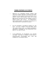
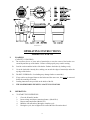
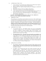
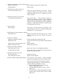
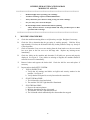
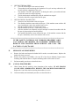
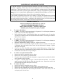
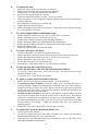
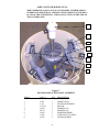
OPERATION & SERVICE MANUAL FOR
MODELS 215 and 216
INVERTER DRIVEN
SINGLE and THREE PHASE MACHINES
BOCK CENTRIFUGES
BEP
TEST & INSPECTION SHEET
SOLD TO _____________________________
MACHINE
_______________ MODEL
_______________ BOCK ORDER #
_______________ SERIAL NUMBER
_______________ DATE
MOTOR & CONTROLS
_______________ INVERTER S/N
_______________ MOTOR VOLTAGE
_______________ CONTROL VOLTAGE
_______________ MOTOR MFG
_______________ INCOMING POWER
_______________ MOTOR S/N
_______________MOTOR HORSEPOWER
_______________ MOTOR RPM
_______________ MOTOR PULLEY SIZE
_______________ MOTOR CODE NO.
_______________ DRIVE BELT
DRIVE UNIT AND BASKET
_______________ UNIT PULLEY SIZE
_______________ BASKET RPM (MAXIMUM)
_______________ BASKET WEIGHT CAPACITY
TESTING RESULTS
_______________ PROCEDURE NUMBER USED
_______________ STARTING AMPS
_______________ RUNNING AMPS
_______________ BRAKING TIME
_______________ INSPECTORS INITIALS
BOCK ENGINEERED PRODUCTS, INC
3600 SUMMIT ST.
TOLEDO, OHIO 43611
REV C 2/22/01
FORM Z-00860
TEST RESULTS #1
FL MODEL CENTRIFUGES
S.O. #__________________________
CUSTOMER ____________________
SERIAL # ______________________
INVERTER SERIAL # ______________________
PANEL SERIAL # ______________________
PLC PROGRAM VERSION ______________________
1. CYCLE TEST MACHINE 10 TIMES WITH MAXIMUM LOAD OF BASKET
CAPACITY, INCLUSIVE SAFETY EVALUATION. CHECKED BY: __________
2. 5 OF THE 10 TEST CYCLES FILL BASKET WITH WATER AND CHECK FOR
SEAM AND LID LEAKS.
CHECKED BY: __________
3. 3 OF THE 10 TEST CYCLES RECORD CYCLE TIME.
_____MINS. & _____SEC.
_____MINS. & _____SEC.
_____MINS. & _____SEC.
4. WELD COSMETICS CHECKED BY: ____________
5. PAINT COSMETICS CHECKED BY: ____________
6. WEIGHT CAPACITY ETCHED ON BASKET. __________LB.
7. COINAGE _________ CENTS
8. SERVICE KEY AND BOX # __________________
9. COIN METER MFG. _______________________
10. COMMENTS ON MACHINE AND
OPTIONS:_________________________________________________________
__________________________________________________________________
11. INSPECTOR'S NAME: ___________________________________________
ii
SCOPE OF MANUAL
This manual is the operation and service manual for inverter driven model 215 & 216
machines manufactured beginning January 2001 with Baldor motor and board level PLC.
KB inverter added starting 10/03
TABLE OF CONTENTS
THREE IMPORTANT POINTS .....................................................................................1
PREPARATION FOR USE AND INSTALLATION INSTRUCTIONS .......................2
I. UNPACKING INSTRUCTIONS: .................................................................2
II. PREPARING YOUR MACHINE FOR INSTALLATION: .........................2
III. INSTALLATION: ......................................................................................2
MOUNTING PRECAUTIONS ...............................................................2
IV. SAFETY SYSTEM TEST: ............................................................................3
FIGURE 1 - MANUALLY RELEASING THE FRONT LATCH..................................5
SERVICE DATA CHART ..............................................................................................5
FIGURE 2 - LABEL LOCATIONS ................................................................................6
OPERATING INSTRUCTIONS .....................................................................................6
I. LOADING: ....................................................................................................6
II. OPERATION:................................................................................................6
SEQUENCE OF OPERATION
MODELS 215I AND 216I...............................................................................................9
I. STARTING SEQUENCE:.............................................................................9
II. STOPPING SEQUENCE: .............................................................................9
COIN COUNTER MODULE..........................................................................................10
I. HOW TO SET THE NUMBER OF COINS TO OPERATE THE
MACHINE:...................................................................................................10
FIGURE 3 - OPERATION WITH A CARD READING SYSTEM ...............................11
SERVICE INFORMATION
14 I/O CONTROLLER -- INPUT AND OUTPUT LIGHTS..........................................12
14 I/O CONTROLLER -- INDICATOR LIGHTS ..........................................................13
INVERTER FAULT CODES (WOODS INVERTER)...................................................13
INVERTER FAULT CODES (KB GENESIS INVERTER) ..........................................13
FIGURE 4 - 216I SCHEMATIC / WIRING DIA (WOODS INVERTER) ....................15
FIGURE 5 - 216I SCHEMATIC / WIRING DIA (KB GENESIS INVERTER)............15
iii
TROUBLE SHOOTING GUIDE
MODELS 215 AND 216 .................................................................................................16
SCHEDULED MAINTENANCE PROGRAM
MODELS 215 AND 216 .................................................................................................18
I. MONTHLY PROCEDURES.........................................................................18
II. SEMIANNUAL PROCEDURES ..................................................................19
III. ANNUAL PROCEDURES............................................................................19
MAINTENANCE AND SERVICE NOTICE .................20
MACHINE SERVICE
A. To remove the basket:....................................................................................20
B. To replace the basket: ....................................................................................20
C. To remove or replace the Hex Ball:...............................................................20
D. To remove the curb: .......................................................................................20
E. To replace the curb: .......................................................................................21
F. To replace Bumper Rubbers and Bumper Caps:............................................21
G. To remove and replace the Motor:.................................................................21
H. To open and close the Control Panel Cover: .................................................21
I. To adjust or replace the lid closed Micro Switches:......................................21
J. To replace the Coin Meter Mechanism (Model 216): ...................................21
K. To adjust the cycle time: ................................................................................22
FIGURE 6 - CHANGING MACHINE CYCLE TIME .......................................22
FIGURE 7 - SCAN LIGHT LOCATION............................................................23
PARTS LIST FOR MODEL 215/216..................................................................24
FIGURE 8 - MOTOR, BASE & TRUNNION ASSEMBLY..............................24
FIGURE 9 - FRONT LATCH ASSEMBLY .......................................................25
FIGURE 10 - REAR PIVOT ASSEMBLY .........................................................26
FIGURE 11 - LID, BASKET & CURB ASSEMBLY ........................................27
FIGURE 12 - PANEL ASSEMBLY (WOODS INVERTER).............................28
FIGURE 13 - PANEL ASSEMBLY (KB GENESIS INVERTER) ....................28
INVERTER INITIALIZATION (WOODS INVERTER)...................................29
INVERTER INITIALIZATION (KB GENESIS INVERTER)...........................29
WARRANTY INFORMATION.................................... INSIDE REAR COVER
216iman.doc 10/03 Ver. 2.3
iv
THREE IMPORTANT POINTS
1.
REMOVE ALL SUPPORTS FROM (UNDER AND
AROUND) BASKET BEFORE STARTING MACHINE.
WHEN PLACING BASKET IN THE MACHINE, SET IT
GENTLY ONTO THE PLASTIC BALL (TO AVOID
BREAKAGE) AND ROTATE THE BASKET UNTIL IT
DROPS DOWN AND SEATS. AN IMPROPERLY
INSTALLED BASKET CAN RESULT IN DAMAGE TO
THE CENTER POST AND/OR GYRO BALL.
2.
DO NOT RESTRICT OR REDUCE DRAIN IN ANY
WAY. DO NOT CONNECT THE MACHINE ONTO
THE SAME DRAIN LINE AS OTHER EQUIPMENT.
FAILURE TO ADHERE TO THE FOREGOING MAY
RESULT IN A BACK WASH.
3.
IT IS ESSENTIAL TO MAINTAIN ALL SAFETY
SYSTEMS. FAILURE TO ADHERE TO THE SAFETY
MAINTENANCE STANDARDS MAY VOID THE
WARRANTY OF THIS MACHINE.
PREPARATION FOR USE AND INSTALLATION INSTRUCTIONS
MODELS 215 AND 216
I.
UNPACKING INSTRUCTIONS:
A.
INSPECT your packaged machine for shipping damage. Look for holes or tears in the
packaging materials and any other outward signs of damage. REPORT ALL DAMAGE
TO THE TRANSPORTATION COMPANY IMMEDIATELY.
B.
Remove packaging from around your machine.
II.
PREPARING YOUR MACHINE FOR INSTALLATION:
A.
OPEN THE LID of your centrifuge by first removing the small #6-32 socket head screw
from the front of the cover which is seated over the front latch. SEE FIGURE 1 (page 5).
Insert the small hex key into the screw hole and firmly push against the front latch bolt.
This procedure will release the latch. You may have to move the hex key around a little
to 'find' the front of the latch bolt. When the latch has released and the lid has lifted
slightly, remove the hex key and replace the screw into its hole.
B.
REMOVE THE BASKET: Have two or three people hold the inner lip of the basket and
lift straight up. You may also employ an overhead hoist if one is available. Set the
basket aside. (CAUTION: Basket weighs 145 lbs.) Remove cardboard packing from
inside the curb assembly.
C.
INSPECT the top of the plastic basket ball for cracks, and grease the ball with medium
weight lithium grease.
D.
MOVE MACHINE on pallet to desired location.
E.
REMOVE MACHINE FROM PALLET by removing the bolts through the feet of the
machine and sliding the machine off the pallet.
F.
INSPECT the exterior of the machine for shipping damage. Look for dents or scratches
in lid, curb assembly, skirt, or control box. REPORT ALL DAMAGE TO TRUCKING
COMPANY IMMEDIATELY.
III.
INSTALLATION:
A.
MOUNTING:
1.
2.
3.
4.
5.
6.
MARK HOLES on floor for the front legs and rear legs by moving the machine
into place and marking the hole locations through the holes in the legs. Make sure
to allow adequate space behind the machine for servicing the rear control panel.
DRILL MOUNTING HOLES. Use 2-1/2" X 1/2" lag bolts into lead anchors in a
concrete floor. (Mounting hardware is not included.)
BOLT machine into place. Do not tighten bolts.
LEVEL MACHINE. Use metal shims under legs if necessary.
TIGHTEN all mounting bolts.
REPLACE BASKET. Be sure that all cardboard packing has been removed
from under the basket. Turn basket slightly to be sure basket has seated.
Basket should turn and pivot freely.
MOUNTING PRECAUTIONS
B.
*
NEVER USE RESILIENT PADS UNDER LEGS.
*
*
MOUNT MACHINE ON LEVEL SURFACE.
CHECK BOLTS PERIODICALLY FOR TIGHTNESS.
INSTALLING THE DRAIN:
1.
2.
The drain should pitch at least one inch per foot for proper flow.
The drain's flow should not be restricted or reduced.
2
3.
C.
ELECTRICAL CONNECTION:
1.
2.
3.
4.
IV.
The drain should dump into an open sump or be vented to prevent water backup
which may cause unwarranted damage to the motor.
INSPECT the data plate on the machine to confirm the required input voltage and
amperage, and whether single or three phase power is required.
DISCONNECT BOX: The centrifuge should be connected to its own electrical
disconnect box, which should be remotely mounted. DO NOT mount the
disconnect box on the machine. For proper fusing see SERVICE DATA CHART
on page 5.
NATIONAL ELECTRICAL CODE: All wiring, motor and circuit disconnecting
devices must be installed in conformance with the National Electrical Code and
applicable local codes.
CONNECTION OF CENTRIFUGE:
a. Open the door to the electrical box on the rear of the machine.
b. Turn off incoming power from the disconnect box.
c. Wire the free end of the electrical cable into your junction box. The cable will
have 3 power wires and a ground wire for three phase machines. Single phase
installations will have two power wires and a ground. A piece of sealtite
flexible conduit is provided with the machine. Inspect the connection of the
power wires into the disconnect box.
d. Turn on incoming power.
e. Turn on the circuit breaker inside the electrical box.
f. The inverter requires a few seconds to initialize. After the computer and
inverter have initialized (approx. six seconds) a signal is sent to the inverter.
This will cause the inverter to spin the basket for a few seconds. After it has
stopped, the lid will open. The entire sequence takes from 15 to 20 seconds,
and will take place whenever main power is applied to the centrifuge (if the lid
is closed and locked). If the lid is open, the computer assumes that the basket is
stopped, and will not cycle the inverter.
g. The direction of rotation is determined by the wiring from the inverter to the
motor, and will not change by reversing the input voltage connections. It does
not matter which direction the centrifuge rotates.
h. Replace the back panel cover (or close the door).
i. Test the operation of your centrifuge by closing the lid and starting the machine.
Timer Models (Model 215) -- Push the start/stop button. Coin Operated Models
(Model 216) -- Insert the proper coinage and push the start/stop button.
SAFETY SYSTEM TEST:
A.
Verify that all warning labels are legible and securely attached to the machine.
SEE FIGURE 2.
B.
Make sure that the back door is securely closed.
C.
START THE MACHINE:
1.
2.
D.
PUSH BUTTON TO STOP THE MACHINE:
1.
2.
E.
"MACHINE IN USE" light should be on.
Lid should be firmly closed and locked.
Machine should stop in less than 90 seconds.
"MACHINE IN USE" light should go out and lid should unlock
automatically.
RE- START MACHINE:
3
1.
2.
3.
4.
5.
6.
F.
Close lid and push start/stop button.
"MACHINE IN USE" light should be on.
The machine should re-start and run through its complete cycle. The
machine should stop in less than 90 seconds of the end of its cycle.
"MACHINE IN USE" light should go out after the machine has stopped.
Lid should unlock automatically at the end of the cycle.
The basket should not be spinning when the lid is opened.
LID OPEN TEST:
1.
2.
3.
With the lid open, attempt to start the machine by pushing the start button.
The machine should not start with the lid open.
"MACHINE IN USE" light should NOT be on.
IF THE SAFETY SYSTEM IS NOT WORKING PROPERLY, OR IF
ANY LABELS ARE MISSING OR ILLEGIBLE, TAKE THE
CENTRIFUGE OUT OF SERVICE IMMEDIATELY.
CONSULT
THE
FACTORY
AT
(419)
726-2645
FOR
REPLACEMENT LABELS OR ASSISTANCE CORRECTING ANY
SAFETY ISSUES.
4
FIGURE 1
SERVICE DATA CHART
SPECIFICATIONS
MODEL 215I/216I
BASKET CAPACITY
BASKET HEIGHT
BASKET DIAMETER
BASKET SPEED
"G" FORCE
TIMER RANGE (215 or 216)
DRIVE TYPE
MOTOR SIZE
35 POUNDS
11.5 INCHES
20 INCHES
1725 RPM
850
3, 4, 5, OR 6 MINUTES (SELECTABLE)
DIRECT, DRIVEN BY INVERTER
2 HP.
RECOMMENDED ELECTRICAL SERVICE (Slo-Blo Fuses)
208-240 / 60 / 3 PHASE
460 / 60 / 3 PHASE
380-415 / 50 / 3 PHASE
208-240 / 60 / 1 PHASE
20 AMPS
10 AMPS
10 AMPS
20 AMPS
DIMENSIONS
HEIGHT TO CURB TOP
DRAIN HEIGHT
DRAIN SIZE
FLOOR AREA REQUIRED
NET WEIGHT
SHIPPING WEIGHT
EXPORT SHIPPING WEIGHT
36 INCHES
11.5 INCHES
2 INCH O.D.
29 x 35 INCHES
460 POUNDS
550 POUNDS
650 POUNDS
5
FIGURE 2
OPERATING INSTRUCTIONS
MODELS 215 AND 216
I.
LOADING:
A.
(CAPACITY 35 POUNDS)
Do not allow sleeves or loose ends of material(s) to cross the center of the basket or to
extend beyond the top of the basket. Failure to load properly may result in tearing.
B.
Load in wads around the inside of the basket. Balance the basket by loading evenly.
C.
Cover the load with a laundry disc, making sure to tuck the edges of material(s) under the
top edge of the basket.
D.
DO NOT OVERLOAD. Overloading may damage clothes or material(s).
E.
If any articles are dropped between the basket and the outer case, they must be removed
before the centrifuge is started.
F.
Loading instructions are provided on the inside of the lid.
G.
THE MAXIMUM DRY WEIGHT CAPACITY IS 35 POUNDS.
II.
OPERATION:
A.
TO START THE CENTRIFUGE:
1.
2.
3.
4.
5.
Close the lid until it latches.
Insert coinage and depress start/stop button. (Model 216).
Depress start/stop button. (Model 215).
Machine will start and run through a complete cycle.
During the cycle, the red light will be on and the lid will remain closed.
6
B.
AT THE END OF THE CYCLE:
1.
2.
3.
4.
5.
6.
At the end of the cycle, the motor stops running forward. and the inverter begins to
stop the centrifuge. The lid will remain closed and locked.
When the basket has completely stopped spinning, the red light goes out and the lid
will unlock.
When the lid unlocks, it will raise up slightly at the latch end.
Lift the lid to a completely open position and unload the basket.
At the conclusion of the cycle, if the lid remains latched, depress the lid open
button, then lift the lid to a completely open position to unload the basket.
Never try to force the lid to open if the red light is on. The red light on indicates
that the basket is still spinning.
CAUTION: THE CENTRIFUGE SHOULD BE TAKEN OUT OF SERVICE IF
THE LID CAN OPEN WHILE THE BASKET IS SPINNING.
C.
EMERGENCY STOP:
This centrifuge has a dual function start/stop button (red in color). If the machine begins
to vibrate excessively during the running cycle or at the start of the run cycle, or should
the need arise to stop the machine for any other reason, the red start/stop button should be
depressed. Depression of the button will stop the machine. After the machine has
stopped, the lid will unlatch as described above. Open the lid and redistribute the load,
checking to make sure that nothing has dropped between the basket and the outer case, or
investigate and correct any other cause of the vibration or noise. To restart the centrifuge,
close the lid until it latches, then depress the red start/stop button.
D.
E.
ADJUSTING CYCLE TIME:
1.
Coin operated model 216: This machine operates on a pre-set, pre-programmed
cycle time of 3 minutes per cycle. The pre-set time is installed at the factory and
can only be modified by selecting different inputs on the controller. (See
instructions in service manual.) This is the shortest time cycle recommended for
optimum moisture removal from clothing.
2.
Timer-operated model 215: The cycle time for this machine is controlled by the
two timing inputs on the programmable controller that is installed inside the rear
control panel. It can be accessed by opening the rear control panel cover. The
available times are 3, 4, 5, or 6 minutes, and is factory pre-set to 3 minutes. The
cycle time may be changed by selecting different inputs on the controller. (See
instructions in service manual.) The centrifuge will run the new cycle time until it
is changed. If the centrifuge is stopped during a cycle, the timer will automatically
reset. When restarted, it will run a complete cycle.
OPERATION OF SAFETIES:
1.
The lid must be closed before the machine can be started. Micro switches sense the
closure of the lid. Two switches are mounted at the rear of the lid hinge tube. The
lid must be firmly closed for each switch to sense a fully closed position and allow
the machine to operate.
2.
In addition to the lid being fully closed, the lid must be locked to allow the
machine to operate. A locked position is sensed by the lid lock switch that is
located inside the front latch cover. The lid lock switch is operated by the lock
bolt. The bolt must be in the locked position to allow the machine to operate. An
additional switch is attached to the lid unlock mechanism. This switch is
electrically wired to the lid locked switch so that the only time a contact closure is
provided is when the lid is closed and locked.
7
3.
A relay in the inverter indicates rotation of the centrifuge. It supplies this
information to the controller which keeps the lid locked whenever it is rotating.
When the motor stops, the relay changes state to allow the lid to open.
4.
A temperature sensor is located on the outside rear of the stainless steel curb,
between the curb and the electrical control box. If it activates during operation, the
machine will shut off immediately. It is usually an indication that something is
hanging out of the basket, rubbing against the interior of the machine while it is
spinning. If this occurs, make sure that everything is contained within the basket,
and that the laundry disk is properly installed. The machine will not restart until it
cools.
5.
Failure of any safety switch or overload device will automatically cause the
machine to come to an orderly shutdown. The failure must be corrected before the
machine will restart.
6.
If a power failure occurs during operation of the centrifuge, the lid will remain
locked. If it is still spinning when power is restored, the machine will stop and
then open.
IF ANY OF THESE SAFETIES ARE NOT WORKING PROPERLY, THE
MACHINE SHOULD BE TAKEN OUT OF SERVICE IMMEDIATELY .
CALL (419) 726-2645 FOR ASSISTANCE.
8
SEQUENCE OF OPERATION
MODELS 215 AND 216
14 I/O CONTROLLER
I.
STARTING SEQUENCE:
A.
CLOSE THE LID: This engages the lid closed and lid locked switches. Input indicator
lights numbers 5 and 6 will turn on. If either one of these lights fails to come on, the
machine will not start.
B.
INSERT COINAGE: (COIN MECHANISM EQUIPPED MODEL 216 ONLY)
This model is equipped with a coin counter module that is set for the coinage required to
operate the centrifuge. See Coin Counter Module Operation for details. When the proper
coinage has been received by the coin counter module, a relay on the interior panel will
energize momentarily. This will cause input indicator light #1 to illuminate momentarily.
If all other safety mechanisms are properly engaged, the machine is ready for operation.
C.
PUSH THE START/STOP BUTTON: The depression of the start/stop button will cause
input indicator light #4 to illuminate. Output lights #1, #3 and #4 will turn on. The
machine will begin to run its cycle. If the machine is currently in operation, depressing
the start/stop switch will cause the centrifuge to stop.
D.
When the start/stop button is initially depressed, output indicator lights #1 & #4 will turn
the inverter on and start the motorl. Input indicator light #2 will turn on indicating
rotation of the motor.
E.
The start/stop button acts as a stop button when the machine is running. Depression of
the button will stop the machine.
II.
STOPPING SEQUENCE:
A.
Elapsed time, per the pre-set timer cycle, expires. (Or the stop button is pushed.)
B.
The run signal is removed from the inverter. Output indicator lights #1 & #4 will turn
off.
C.
The run signal light ,(input indicator light #2) remains on while the motor is rotating, and
will continue to keep the lid locked until the machine has come to a complete stop.
D.
When the basket comes to a complete stop, input indicator light #2 and output indicator
light #3 will turn off, and the lid unlatch solenoid output indicator light #2 illuminates,
indicating the lid is unlatching. The lid solenoid will engage for two seconds. Input
lights #5 and #6 also turn off at this time, unless the lid does not raise.
E.
If the lid solenoid operates but the lid remains closed, the operator should depress the lid
open button. Input indicator light #3 will illuminate and the lid will unlatch. The lid can
then be opened by the operator.
F.
When the lid is opening or is fully opened, the lid locked light, (input light #5), and the
lid closed light, (input light #6), will be off.
9
SEQUENCE OF OPERATION
COIN COUNTER MODULE
MODEL 216
I.
HOW TO SET THE NUMBER OF COINS TO OPERATE THE
MACHINE:
NOTE: If the machine is equipped with a card reading system, refer to the card reader instructions.
A.
This module is located in the rear of the coin meter case and can be accessed by using the
key to open the rear service door.
B.
The module is the small blue square block with 5 wire terminals and a bank of 4 switches.
C.
The 4 switches are located on the front face of the block at the top.
D.
The 4 switches control the number of coins that are required to operate the machine. On
the left side of the switches are the words "on" and "off". Across the bottom of the
switches are the numbers 1, 2, 4 and 8. Across the top of the switches are the numbers 1,
2, 3, and 4.
E.
To set the number of coins -- follow these instructions:
1.
2.
3.
4.
5.
6.
7.
8.
9.
For 1 coin, set switch number 1 to the "on" position and all other switches to "off".
For 2 coins, set switch number 2 to the "on" position and all other switches to
"off".
For 3 coins, set switches number 1 and 2 to the "on" position and all other switches
to "off".
For 4 coins, set switch number 3 to the "on" position and all other switches to
"off".
For 5 coins, set switches number 1 and 3 to the "on" position and all other switches
to "off".
For 6 coins, set switches number 2 and 3 to the "on" position and all other switches
to "off".
For 7 coins, set switches number 1, 2 and 3 to the "on" position and all other
switches to "off".
For 8 coins, set switch number 4 to the "on" position and all other switches to
"off".
Up to 15 coins can be set using the various switch combinations.
10
1221
1350
Figure 3
OPERATION WITH A CARD READING SYSTEM
The BOCK model 216I can easily be modified to operate with a card reading system. Normally
this machine operates with a coin mechanism. All the controller requires is a momentary contact
closure (100ms) from wire 1221 to wire 1350. (See Figure 3 or the schematic/wiring for details.)
11
SERVICE INFORMATION
MODELS 215 AND 216 WITH INVERTER DRIVE
CONTROLLER INPUT AND OUTPUT LIGHTS
INPUT
LIGHT #
1
2
DESCRIPTION
FUNCTION
Model 215
Light is on when start button is pushed.
Model 216 (coin mechanism light)
Light is on for approximately 1/2 second after coins
have been deposited.
Motor rotation signal
light from inverter
This light is on whenever the motor is operating.
3
Lid open light
Normally off. Light is on only when the lid open
button is depressed.
4
Start/Stop light
Normally off. Light is on only when the start/stop
button is depressed.
5
Lid locked light
Light is on when lid is closed and locked.
6
Lid closed/curb thermal overload light
Light is on when the lid is closed and locked AND
the thermal overload located on the rear of the curb
is okay.
7
Time select bit 1
Light is on or off depending upon the cycle time
selected. (Normally off)
8
Time select bit 2
Light is on or off depending upon the cycle time
selected. (Normally off)
OUTPUT
LIGHT #
1
Motor run light
Light is on when the motor is in operation during the
regular cycle.
2
Lid lock solenoid light
Light is on when unlocking the lid. This sends
power to the lid lock relay which in turn powers the
solenoid for unlocking the lid.
3
Machine "In Use" light
Light is on when the machine is being operated.
12
CONTROLLER INDICATOR LIGHTS
LIGHT
FUNCTION
Input lights
Numbered 1 through 8, these lights are on whenever the
corresponding input is turned on.
Output Lights.
Numbered 1 through 6, these lights are on whenever the
corresponding output is turned on.
Scan light.
This light is on whenever there is power to the controller
and the program is running. The light flashes if there is a
problem with the controller or the program.
INVERTER FAULT CODES (WOOD’S E-TRAC® INVERTER)
Knowledge of the output frequency and other conditions at the time a fault occurs makes diagnosis
of inverter faults much easier. These conditions may be observed until the fault is reset. After it
is reset, the parameters will return to zero. To access the information, push the PROG button on
the inverter then push the ENTER button. The inverter will momentarily display Err, then display
parameter 21. Push the down arrow to access parameters 12 through 16.
Parameter Descriptions
Parameter 12
Parameter 13
Parameter 14
Parameter 15
Parameter 16
Motor Output Frequency
Motor Output Voltage
Motor Output Current
Drive Load
Load Torque
13
FAULT
CAUSE
POSSIBLE REMEDY
F01
INVERTER
MALFUNCTION
PRESS STOP KEY FOR LONGER THAN 1 SECOND
TO RESET. CONSULT FACTORY IF PROBLEM
PERSISTS.
F03
BUS CURRENT ERROR
PRESS STOP KEY TO RESET. CONSULT FACTORY
IF PROBLEM PERSISTS.
F04
POWER SUPPLY
OVERLOAD
CHECK FOR PROBLEM ON V+ LINE.
F05
NO DC BUS VOLTAGE
CHECK POWER RESISTOR FOR SHORT. CONSULT
FACTORY IF PROBLEM PERSISTS.
F06
OUTPUT SHORT CIRCUIT
CHECK MOTOR WIRING. REMOVE MOTOR WIRES
& RECHECK.
F07
EXTERNAL FAULT
NOT USED
F11
GROUND FAULT
CHECK MOTOR WIRING. REMOVE MOTOR WIRES
& RECHECK.
F13
OVERVOLTAGE ON DC
BUS
VERIFY LINE VOLTAGE. INCREASE
DECELERATION RAMP TIME.
F16
ACCELERATION
OVERCURRENT
MECHANICAL OVERLOAD ON MOTOR. CHECK
MOTOR WIRING. INCREASE ACCELERATION
RAMP TIME.
F17
DECELERATION
OVERCURRENT
INCREASE DECELERATION RAMP TIME.
F18
RUNNING
OVERCURRENT
MECHANICAL OVERLOAD ON MOTOR
F19
HEATSINK OVER
TEMPERATURE
CHECK FOR EXCESSIVE OVERLOAD ON DRIVE.
14
INVERTER FAULT CODES (KB GENESIS INVERTER)
Function F125 logs the last 3 faults which have ocurred. The fault memory may be cleared by
pushing the ◄/reset key to while displaying the function. See inverter initialization for details of
how to access this function.
FAULT
DESCRIPTION
CAUSE / POSSIBLE REMEDY
Err7
BUS VOLTAGE ERROR
BUS VOLTAGE NOT WITHIN TOLERANCE..
CPF
PROGRAM ERROR
ADD NOISE FILTERING
EPR
EEPROM DEFECTIVE
REPLACE DRIVE
OU
HIGH AC LINE VOLTAGE
MEASURE TO DETERMINE VOLTAGE – CORRECT
LU
LOW AC LINE VOLTAGE
MEASURE TO DETERMINE VOLTAGE – CORRECT.
OH1
BRAKE RESISTOR
OVERLOAD
INCREASE DECEL TIME (F002)
MACHINE OVERLOADED
OL1
MOTOR OVERLOAD
MACHINE OVERLOADED – FAULTY DRIVE OR
MOTOR
OL2
DRIVE OVERLOAD
MACHINE OVERLOADED – FAULTY DRIVE OR
MOTOR.
OL3
OVERTORQUE
MACHINE OVERLOADED – FAULTY DRIVE OR
MOTOR.
OC-S
TRANSIENT
OVERCURRENT
BAD MOTOR BEARING.
OC-A
ACCELERATION
OVERCURRENT
INCREASE ACCEL TIME (F001)
OC-C
OVERCURRENT AT SET
SPEED
CHECK FOR EXCESSIVE OVERLOAD ON DRIVE.
OC-d
OVERCURRENT DURING
DECEL
INCREASE DECEL TIME (F002)
OC-b
OVERCURRENT DURING
BRAKING
ADJUST DC INJECTION SETTINGS
OU-C
OVERVOLTAGE AT SET
SPEED OR DURING DECEL
INCREASE DECEL TIME (F002)
BUS VOLTAGE ERROR
CHECK AC LINE & BUS VOLTAGE
Err7
FAULTY DRIVE
LINE VOLTAGE VARIATION
15
Figure 4
MODEL 216I SCHEMATIC DIAGRAM (WOODS INVERTER)
16
TROUBLE SHOOTING GUIDE
MODELS 215 AND 216
Problem and possible cause
Potential correction
1. Machine fails to start
No power to machine
Controller scan light off (Fig 6)
Internal circuit breaker turned off. Check electric
service - Fuse required as described on Service Data
Chart.
Check internal fuses.
Lid not closed
Close lid - Input light #6 must be on when lid is
properly closed, (activating each safety switch), and
the thermal overload on the curb is okay.
Lid not locked
Close lid - Check for proper engagement of lid lock
bolt. Check for proper operation of the top switch
with the latch bar. The #5 light will be on when lid is
properly closed and locked.
Inverter fault
Check display on inverter to determine type of fault
(see pg. 13). Push red button on Woods inverter or
reset button on KB Genesis inverterto reset.
Motor forward signal not turning on
Check #1 & #4 output lights on controller - If lights
turn on, check the wiring to the inverter from the
controller for breaks or loose wires.
Coin mech. not sensing pulses (216)
Check #1 input light when depositing coins - The
light should turn on momentarily when the proper
number of coins are deposited. If the light never
turns on, check the coin counter module in the meter
case. Check drop coin mechanism. Check coin relay
Controller scan light flashing
Controller or program error – replace controller.
2. Lid opens when basket is spinning
Front latch is misaligned and not locking Check alignment and adjust as necessary.
Weak or broken spring in front latch
Replace spring.
Inverter fault
Check display on inverter to determine type of fault.
Replace inverter
3. Machine runs but indicator light is not on.
Light burned out or problem with controller
or wiring
Check #3 output light on controller - If #3 light is on,
replace "IN USE" light. Otherwise, check wiring
harness for breaks or other damage.
4. Machine requires more than 2 minutes to stop.
Braking resistor defective.
5. Machine keeps running
Check display and status light on inverter to
determine whether or not the inverter is actually
driving the motor or if the machine is coasting.
Controller output shorted
17
6. Main circuit breaker on wall keeps blowing
Breaker rated too low
Check amperage against Service Data Chart.
Wiring problem
7. Machine starts without coins (216)
Coin counter module or relay
8. Machine runs short cycle and stops
or machine stops during cycle
9. Water on floor
Drain plugged
Repair wiring.
Check coin counter module & coin relay. Inspect
wiring for damage and/or replace module. #1 input
light should only turn on for a moment as the coin
count is reached.
Start button faulty. Check thermal overload on
machine curb and safety switches - Allow machine to
cool if necessary before trying to re-start. If machine
still does not start, check safety switch input lights on
controller. If light flashes when lid is opened, check
for intermittent safety switch.
Check drain - Clear the drain of any blockages. The
drain should have at least a 2 inch line and drainage
should slope 1 - 2 inches per foot.
10. Knocking noise when starting or stopping
Basket ball worn.
Replace the basket ball and grease its top. Check
inside of center post for wear. Replace if edges are
rounded.
11. Excessive vibration
Machine is improperly loaded
Basket ball is dry
Motor mount or trunnion rubbers worn
Basket center post is worn
12. Rattles in the latch mechanism
Latch parts may be loose
Foreign material in latch
13. Machine will not accept coins
Box is full of coins
Coin mechanism is broken
Stop the machine and rearrange the load.
Grease the basket ball with medium weight lithium
grease.
Replace rubbers.
Replace the center post.
Remove the front cover and tighten latch parts.
Remove the front cover and check for the presence of
foreign material in the latch.
Empty the coin box.
Replace coin mechanism.
14. Status (machine running) light flashing. Lid open after coins inserted – Normal condition.
Light will stop flashing when lid is closed & locked.
Safety switch (lid closed or lid locked) or thermal
overload opened during cycle. This fault will reset
when the following conditions are met:
a. Motor stopped signal is received from the
inverter. (Input light #2 off)
b. Lid locked micro switches are closed. (Input
light #5 on)
c. Lid closed micro switches and thermal overload
located on the rear of the curb are closed. (Input
light #6 on)
18
SCHEDULED MAINTENANCE PROGRAM
MODELS 215 AND 216
***********************************************************************
*
Read thoroughly before operating your centrifuge.
*
Your Bock centrifuge requires scheduled maintenance.
*
Always disconnect power before working on any part of the centrifuge.
*
For your safety, never force the lid open.
*
Do not attempt to load or unload if the basket is spinning.
*
Always instruct end users on all operational and safety procedures prior to their
operation of the centrifuge.
*********************************************************************
I.
MONTHLY PROCEDURES
A.
Check the machine mounting bolts to verify that they are tight. Retighten if necessary.
B.
Check the lid to determine that the gas spring is working properly. Hold the lid up
approximately 12 inches; the lid should either stay in that position or drop very slowly to
a closed position.
C.
Check to determine if any screws are missing from the front latch cover, the rear control
box cover plate or the rear cover over the hinge tube. Replace any missing screws
immediately.
D.
Check the labels on the machine and determine if all labels are present and properly
displayed. See Figure 2. If any labels are missing or illegible, the machine should be
removed from service immediately.
E.
Remove basket and regrease the basket ball. Check the ball for wear and replace if
necessary.
F.
Inspect and test the SAFETY SYSTEM:
1.
VISUAL INSPECTION:
a. Verify that all warnings and labels are legible and securely attached to the
machine. See Figure 2.
b. Verify that the back panel is securely fastened to the control box.
2.
START THE MACHINE:
a. The lid should be closed and locked.
b. The machine "IN USE" light should be illuminated.
3.
STOP THE MACHINE:
a. Depress the start/stop button.
b. Machine should stop in 60 to 90 seconds.
c. The machine "IN USE" light should turn off.
d. The lid should unlock automatically after the machine has stopped.
19
4.
RESTART THE MACHINE:
a.
Close the lid and depress the start/stop button.
b.
The machine should run through the remainder of its cycle and stop within 60 to 90
seconds after the completion of the cycle.
c.
The machine "IN USE" light should be on during the entire cycle and should turn
off after the motor has stopped spinning.
d.
The lid should unlock automatically after the machine has stopped.
e.
The basket should be stopped when the lid opens.
5.
RESTART WITH LID OPEN TEST:
a.
Attempt to start the machine with the lid open.
b.
The machine should not start with the lid open. If the machine starts with the lid
open, immediately remove the machine from service.
c.
Start the machine with the lid closed and locked.
d.
Stop the machine as in step 3. of the safety test above.
e.
After the machine has completely stopped, attempt to restart the machine with the
lid open by depressing the start/stop button.
f.
The machine should not restart with the lid open. If the machine restarts with the
lid open, immediately remove the machine from service.
*********************************************************************
IF THE SAFETY SYSTEM IS NOT WORKING PROPERLY OR IF
ANY LABELS ARE MISSING OR ILLEGIBLE, IMMEDIATELY
REMOVE THE MACHINE FROM SERVICE AND CALL THE
FACTORY AT (419) 726-2645.
*********************************************************************
II.
SEMIANNUAL PROCEDURES
A.
Remove the basket and inspect the basket ball for cracks or rounded corners. Replace the
basket ball when necessary.
B.
Remove the stainless steel CURB. (See step "D" of the Service Manual) Inspect motor
mounting and trunnion rubbers. Replace mounting rubbers if the motor is loose.
C.
Perform monthly procedures as described above.
III.
ANNUAL PROCEDURES
A.
Check Center Post for cracks by close inspection of the surface. IF ANY CRACKS
CAN BE SEEN, IMMEDIATELY REMOVE THE MACHINE FROM SERVICE.
Replace the Center Post before returning the machine to service.
B.
Perform monthly and semiannual procedures as described above.
20
MAINTENANCE AND SERVICE NOTICE
ALL BOCK centrifuges are provided with safety interlocks to prevent the opening of the lid while
the basket is spinning. These safety features are designed to allow for extended service and
continued use. Their effectiveness, however, can be impaired by customer misuse of the centrifuge
or the failure of the owner to provide regular maintenance. This type of equipment is typically used
on a constant basis and preventive maintenance is required to prevent injury especially to the
unwary.
Proper lubrication and maintenance will provide excellent machine longevity.
A parts manual is included as part of this service manual. The parts are identified in the included
views and are described in the parts list. Please use this information to identify and describe the
parts when ordering replacement parts. In addition, when ordering, please provide the name plate
data including model number, serial number and electrical specifications.
MACHINE SERVICE
BOCK CENTRIFUGE MODELS 215 AND 216
BOCK ENGINEERED PRODUCTS, INC.
3600 SUMMIT STREET, TOLEDO, OHIO 43611
PHONE: (419) 726-2645 FAX: (419) 726-8583
A.
To remove the basket:
1.
2.
B.
Caution: The basket weighs approximately 145 pounds. You will require assistance to
safely remove the basket from the machine.
Raise the lid and secure it from falling back down onto your hands or arms. Do not place
your fingers or hands between the curb sidewall and the basket. Do not drop the basket to
the floor, lower it gently.
To replace the basket:
1.
2.
3.
4.
5.
C.
Caution: The basket weighs approximately 145 pounds. You will require assistance to
safely replace the basket into the machine.
Inspect the basket ball for damage, cracks, etc. Replace if necessary.
Inspect the corners of the Hex Ball. Replace it if the corners are rounded. If the Hex Ball
is damaged, inspect the inside of the Center Post (on the basket) for damage. Replace
these parts as required.
Grease the top of the Hex Ball using a medium weight lithium grease. Failure to do so
may result in excessive vibration that will cause damage to the Center Post and Hex Ball.
Examine the drain and clear it of any blockages.
To remove or replace the Hex Ball:
1.
2.
3.
4.
D.
Remove the basket as described in step A. above.
Remove the screw from the top of the Hex Ball.
Tap on the base of the Hex Ball with a hammer in an upward motion until the Hex Ball is
loose enough to remove by hand.
To replace ... Carefully align the square of the Hex Ball with the Shaft. Use a rubber
mallet to tap the Hex Ball onto the Shaft and replace the screw. Inspect for cracks in the
Hex Ball and/or the Shaft and replace if necessary.
To remove the curb:
1.
2.
3.
4.
Remove the basket as described in step A. above.
Remove the 1/2" bolts, washers and rubber gaskets located inside the curb.
Remove the bolt connecting the gusset to the base (beneath the electrical control box).
Remove the curb with the lid and control panel attached. If the curb is stuck, rock the
curb gently until it breaks loose.
21
E.
To replace the curb:
1.
2.
3.
4.
5.
6.
7.
8.
9.
F.
Inspect the gaskets on the legs and replace if necessary.
Replace the curb on the base assembly and align the holes.
Hand start the 1/2" bolts with gaskets and bent washers.
Insert the bolt securing the gusset to the base.
Tighten the curb bolts until they are snug -- do not over-tighten.
If the curb and the base are not properly aligned, tighten the appropriate curb fasteners to
refine the alignment.
Do not tighten the curb bolts as to bend the curb.
Tighten the bolt securing the gusset.
Replace the basket as described in Step B. above. Inspect the curb for leaks after the first
use. Seal with RTV if necessary.
To replace Bumper Rubbers and Bumper Caps:
1.
2.
3.
4.
5.
6.
7.
G.
Remove the basket and the curb as per steps A. and D. above, respectively.
Remove the Bumper Caps by removing 2 bolts per cap.
Tilt the motor assembly enough to pull off the Bumper Rubbers.
Remove the Bumper Rubbers by sliding them off the motor hangers.
Install replacement Bumper Rubbers by sliding them onto the motor hangers.
Replace the Bumper Caps.
Replace the curb and basket as in Steps E. and B.
To remove and replace the motor:
1.
2.
3.
4.
5.
6.
H.
Disconnect the motor wires inside the electrical control box.
Remove the fitting securing the motor cable at the bottom of the electrical control box.
Remove the basket and the curb as per steps A. and D. above, respectively.
Remove the Bumper Caps as per Step F. 2. above.
Lift the Motor assembly out of the trunnion ring.
Install the new / replacement motor by reversing the above procedure.
To open and close the Control Panel Cover:
1.
2.
3.
I.
TURN OFF POWER TO THE MACHINE BEFORE PROCEEDING.
To open the Control Panel Cover, loosen the two bolts. The fasteners may be easily
disengaged from the door.
To close the cover, reverse the above procedure.
To adjust or replace the lid closed Micro Switches:
1.
2.
3.
4.
J.
Remove the cover from the top rear of the machine. (Over the lid hinge.)
If replacing the Micro Switch(es), mark the outline of the mounting plate prior to
removing the plate. Remove the mounting plate. Mark and remove the wires running to
the Micro Switch and remove the switch. Replace the Micro Switch and reconnect the
wires in the same order as they were previously attached. Reinstall the mounting plate
and adjust the switches as described below.
To adjust the Micro Switch(es), close the lid of the machine. Adjust the Micro Switches
by moving the mounting plate so that the switches close as the lid closes. Note that the
switches are actuated by the tab attached to the lower rear of the aluminum tube. When
the initial adjustment has been made, open and close the lid several times to determine
that the switches are actuating. Tighten the mounting plate when the switches are
operating properly.
Reattach the wires and test the machine to insure proper operation.
To replace the Coin Meter Mechanism (Model 216):
1.
2.
3.
Turn off power to the machine.
Use the key to unlock the service door on the Coin Meter case. Remove the Coin Meter
Mechanism and disconnect the wires at the connector.
Install the new Coin Meter Mechanism by connecting the wires to the limit switch.
Attach the mechanism to the connector.
22
4.
5.
K.
Replace the service door.
Test the machine for proper operation.
To adjust the cycle time (Model 215):
1.
2.
Turn off power to the machine.
Open the Control Panel Cover per Step H. above.
The cycle time for this machine is selected at the controller located on the inside of the door of the
electrical control box at the rear of the machine. The default cycle time is 3 minutes. The time may
be changed to 4, 5, or 6 minutes by adding jumper wires to the #7 and/or #8 inputs at the controller.
(Refer to Figure 5)
To change the time from 3 minutes to 4 minutes:
Connect a jumper wire from input terminal 7 on the controller to the GND terminal on the
opposite side of the controller.
To change the time from 3 minutes to 5 minutes:
Connect a jumper wire from input terminal 8 on the controller to the GND terminal on the
opposite side of the controller.
To change the time from 3 minutes to 6 minutes:
Connect a jumper wire from input terminal 7 to input terminal 8 on the controller.
Connect a jumper wire from input terminal 8 on the controller to the GND terminal on the
opposite side of the controller.
Figure 5
CHANGING MACHINE CYCLE TIME
23
Figure 6
SCAN LIGHT LOCATION
24
PARTS LIST FOR MODEL 215/216
WHEN ORDERING PARTS, ALWAYS GIVE MODEL NUMBER, SERIAL
NUMBER AND ELECTRICAL SPECIFICATIONS (SHOWN ON THE DATA
PLATE OF THE CENTRIFUGE). THIS DATA PLATE IS ON THE SIDE OF
THE CONTROL BOX.
1
5
6
4
7
8
2
3
Figure 7
MOTOR, BASE & TRUNNION ASSEMBLY
ITEM #
PART #
QTY
DESCRIPTION
1
2
3
4
5
6
7
8
25291
C-44
215-023
10340
M-163
10930
31680
22610
1
2
1
2
3
3
3
3
BASKET BALL
TRUNNION RUBBER
MOTOR
BUMPER CAP
BUMPER CAP
BUMPER RUBBER
CURB TO LEG GASKET
TRUNNION RING
25
25
Figure 8
FRONT LATCH ASSEMBLY
ITEM #
PART #
12
13
14
15
17
17A
18
19
20
21
22
23
24
25
200
201
Not Shown
25690
CLEVIS PIN
29830
TEFLON BEARING SPACER
29840
FRONT TUBE COVER
29850
GAS SPRING
29860
FRONT GAS SPRING BRACKET
34950 & 34960 MOUNTING BALL & RETAINER
29870
REAR GAS SPRING BRACKET
29880
LID HINGE TUBE
29970
LATCH ASSEMBLY MTG. PLATE
29790
FRONT LATCH CAP
29740
'LID OPEN' BUTTON
29800
LATCH BAR
29730
'START/STOP' BUTTON
34970
GAS SPRING FASTENER
29990
LID LOCKED SWITCH ACTUATOR BAR
26820
'LID LOCKED' SWITCH
26810
'LID CLOSED' SWITCH (LOCATED ABOVE
LATCH HOOK TOP) (SEE FIGURE 10)
20-0029
SPRING PLATE
10261
SOLENOID RETURN SPRING
20068
LID LOCK SOLENOID
HARDWARE 6-32 x 3/8 SOCKET HD CAP SCREW
29720
PILOT LIGHT
20031
WIRING HARNESS - LATCH ASSY
20032
WIRING HARNESS - TUBE
202
203
204
205
206
207
208
DESCRIPTION
26
Figure 9
REAR PIVOT ASSEMBLY
ITEM #
PART #
DESCRIPTION
17A
18
19
209
210
211
211A
212
212A
213
214
NOT SHOWN
215
216
217
218
219
220
221
222
223
224
34950 & 34960 MOUNTING BALL & RETAINER
29870
REAR GAS SPRING BRACKET
29880
LID HINGE TUBE
24680
MONEY BOX KEY (216 ONLY)
25850
MONEY BOX (WITH KEYS) (216 ONLY)
28560
METER CASE DOOR, LOCK & KEY (216 ONLY)
28940
METER CASE DOOR KEY (#L1131) (216 ONLY)
29140
METER CASE (216 ONLY)
29150
METER CASE SERVICE DOOR ONLY (216 ONLY)
29430
DROP COIN MECHANISM (216 ONLY)
29440
DROP COIN MECHANISM BOLT (216 ONLY)
29710
120V COIN COUNTER
29900
HINGE PIVOT BLOCK (RIGHT SIDE)
29910
HINGE PIVOT BLOCK (LEFT SIDE)
29940
REAR COVER PLATE
29890
HINGE SHAFT
29930/20012 HINGE MOUNTING PLATE 215/216
29960
LID-UP SWITCH MOUNTING BRACKET
26820
'LID CLOSED' SWITCH
23240
PIVOT BEARING
HARDWARE SPACER WASHERS
29950
ACTUATING TAB
27
Figure 10
LID, BASKET & CURB ASSEMBLY
ITEM #
PART #
1
2
3
4
5
6
7
8
8A
9
NOT SHOWN
22520
24150
21250
25200
25040
31690
2400-149-G
29780
29770
21200
20069
28
DESCRIPTION
LID
LID GASKET
BASKET ASSEMBLY (20")
CURB ASSEMBLY
CURB BOLTS (2 or 3)
CURB MOUNT WASHER
RUBBER WASHER
LATCH HOOK TOP
LATCH HOOK BASE
CENTER POST
THERMAL OVERLOAD
1
3
2
4
5
7
8
9
6
10
Figure 11
PANEL ASSEMBLY
ITEM #
1
2
3
4
5
6
7
8
9
10
ON DOOR
PART #
QTY
DESCRIPTION
215-027
215-028
215-029
215-033
FP35-088
FP35-086
20119
20152
215-035
215-031
215-026
1
2
1
1
1
1
1
1
1
1
1
5A FUSE
2A FUSE
1/2A FUSE
RELAY (LID OPEN)
15A CIRCUIT BREAKER
INVERTER
BRAKING RESISTOR
TRANSFORMER
CAPACITOR
BRIDGE RECTIFIER
LOGIC CONTROLLER
29
215 / 216
INVERTER INITIALIZATION PROCEDURE
WOODS INVERTER
The following procedure is performed at initial testing. To return the parameters to these settings,
set parameter 81 for a Data Code of 3.
Programming Procedures
Press the UP/DOWN arrow keys to access the desired parameter. The parameter number will be
displayed in the upper left corner of the digital display.
Press the SHIFT key to allow the Data Code to be changed. PRG will start to blink.
Press the UP/DOWN arrows to select the new Data Code.
Press the ENTER key to store the new Data Code. The display shows STOred for one second.
If accidentally changing the wrong parameter, press the SHIFT button to prevent storing incorrect
data.
When finished with each parameter, press the PROGram key to exit the Program mode or the
UP/DOWN arrows to select a new parameter.
To Adjust Speed Only
Press the UP/DOWN arrows on the inverter to select the new desired frequency.
Press the ENTER key to store the new Data Code. The display shows STOred for one second.
To Adjust all Parameters
Press the UP/DOWN arrows for a setting of 60. (Speed = 1740 RPM)
Press the ENTER key to store the new Data Code. The display shows STOred for one second.
With the inverter in a stop condition, press and hold the SHIFT key, then press the PROGram key.
The display will read 000 with an AC in the upper left corner. Enter the access code and press the
ENTER key. If the correct access code is entered, the PRG indicator will turn on. If not, the
parameters may be displayed but not changed.
Using the above procedures to access the desired parameter, set the following:
Set parameter number 21 to 2. (Input mode)
Set parameter number 42 to 55. (Acceleration time)
Set parameter number 43 to 65. (Deceleration time)
Set parameter number 47 to 4.95. (DC brake time)
Set parameter number 48 to 6.50%. (DC brake voltage)
Set parameter number 52 to 5.00%. (Torque Boost)
Set parameter number 59 to 230. (Rated motor voltage)
Set parameter number 75 to 5. (Auxiliary relay output)
Set parameter number 82 to 6. (Start options)
Press the PROGram key to exit the Program mode.
30
215 / 216
INVERTER INITIALIZATION PROCEDURE
KB GENESIS INVERTER
Programming Procedures
Press the DSP/FUN key to access the programming menu. The function number will be displayed.
Press the UP/DOWN arrows (▲or▼) and/or the ◄/RESET key until the desired function is
reached.
Press the READ/ENTER key to display the present setting.
Press the ◄/RESET key until the digit to be changed is flashing.
Press the UP/DOWN arrows (▲or▼) to change the setting.
Repeat the process for each digit until the desired reading is displayed.
Press the READ/ENTER key to store the reading.
When finished with each function, press the arrow keys (▲, ▼ or ◄/RESET) to select a new
function or the DSP/FUN key to exit the Program mode.
To Adjust Speed Only
Press the arrow keys (▲, ▼ or ◄/RESET) on the inverter to select the new desired frequency.
Press the READ/ENTER key to store the reading.
To Adjust all Functions
Press the arrow keys (▲, ▼ or ◄/RESET) for a setting of 60. (Speed = 1740 RPM)
Press the READ/ENTER key to store the reading.
Using the programming procedures described above, set the following:
Set function number F001 to 45. (Acceleration time)
Set function number F002 to 45. (Deceleration time)
Set function number F010 to 0001. (Run/Stop control)
Set function number F012 to 1000. (Trip prevention)
Set function number F015 to 60. (Trip prevention deceleration time)
Set function number F048 to 0100. (Dynamic brake & Spin start)
Set function number F053 to 5. (DC brake time)
Set function number F054 to 5. (DC brake start frequency)
Set function number F055 to 15. (DC brake level)
Set function number F069 to 1000. (Electronic O/L protection mode)
Set function number F072 to 5. (Torque boost)
Set function number F079 to 10. (Overtorque detection time)
Press the DSP/FUN key to exit the Program mode.
31