1
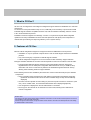
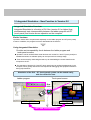
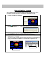
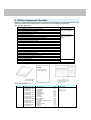
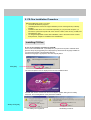
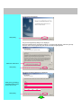
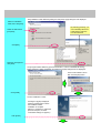
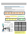
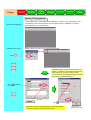
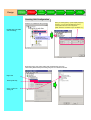
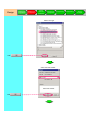
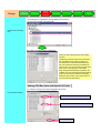
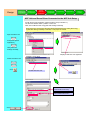
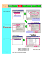
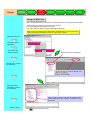
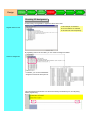
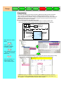
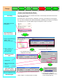
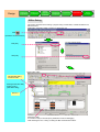
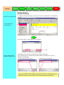
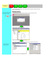
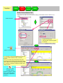
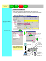
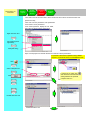
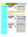
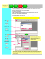
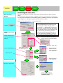
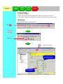
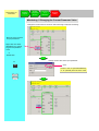
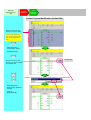
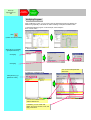
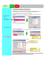
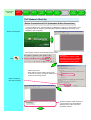
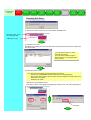
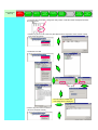
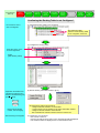
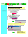
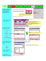
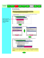
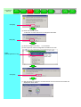
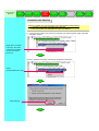
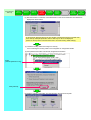
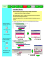
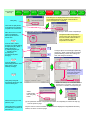
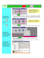
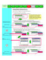
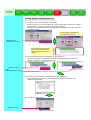
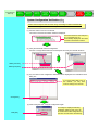
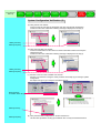
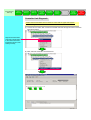
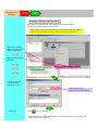
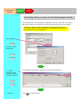
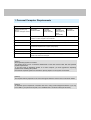
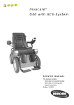
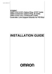
CX-One CD-ROM contains a setup manual PDF file. The Setup manual of CX-One is stored in the following file. / / Disk1: CX-One_Manuals English CX-One Setup Manual W463-E1-01.pdf Before using this product, you must read “Introduction” and “Safety Cautions”. Cautions and detailed explanation are available on Help and PDF Manual. * Acrobat Reader 5.0 or later is required to read the PDF file. Table of Contents Chapter 1 Overview and Installation of CX-One 1. What is CX-One? 2. Features of CX-One 3. Integrated Simulation – New Function in Version 2.0 4. CX-One Component Checklist 5. CX-One Installation Procedure 1-1 1-1 1-2 1-4 1-5 Chapter 2 Example of PLC System Construction by CX-One Workflow in This Chapter 1. Design 1-1. Starting CX-Programmer 1-2. Creating Unit Configuration 1-3. Setting CPU Bus Units and Special I/O Units 1-4. Checking I/O Assignment 1-5. Programming 1-6. Offline Debug 1-7. Saving a Project 2. Online Debug on a Machine 2-1. Reading a Project 2-2. Online Connection to PLC 2-3. Transferring to a Machine 2-4. Program Debug 3. Start-Up / Adjustment On-site 3-1. Program Modification 3-2. Unit Parameter Change 2-1 2-2 2-3 2-5 2-9 2-10 2-12 2-13 2-14 2-15 2-16 2-21 2-23 2-25 Chapter 3 Example of PLC Network System Construction by CX-One Workflow in This Chapter 3-1 1. PLC Network Start-Up 1-1. PLC Start-Up 3-2 1-2. DeviceNet Start-Up 3-6 1-3. NT Link Start-Up 3-8 1-4. Controller Link Start-Up 3-10 1-5. CompoWay/F Start-Up 3-12 1-6. Saving System Configuration 3-15 2. Adjustment On-site 2-1. System Configuration Verification 3-17 2-2. Controller Link Diagnosis 3-19 3. Servo/Inverter Settings 3-1. DeviceNet Connection 3-20 3-2. RS232C Connection 3-21 Chapter 4 Appendix 1. Personal Computer Requirements 4-1 2. List of Software to be Installed 4-2 3. Comparison of Functions Between Conventional Support Software and CX-One 4-3 1. 1. What What is is CX-One? CX-One? CX-One is an FA Integrated Tool Package that integrates Support Software for OMRON's PLC and other Components. To construct an FA System based mainly on PLC, traditionally it was necessary to purchase and install individual Support Software compatible with each Unit, start the software individually, and then connect to PLC and individual Components. Installation of this FA Integrated Tool Package "CX-One" on a personal computer allows integrated operation from setup of OMRON's CPU Bus Units and Special I/O Units (SIOU) and Components to network start-up/monitoring and improving efficiency of PLC System start-up. 2. 2. Features Features of of CX-One CX-One zCX-One allows integrated management of Support Software for OMRON's PLC/Components. y Installation on only one personal computer allows a user to handle Support Software for OMRON's products. y Only one licensing key is required to install all Support Software. y It allows integrated management of one save location for files created by Support Software. z Support Software dedicated to CPU Bus Units and Special I/O Units can be started on the I/O Table. y The appropriate dedicated Support Software can be automatically started by specifying a registered Unit in the I/O Table (Unit configuration table attached to a PLC). In addition, setup information such as PLC model can be passed to the dedicated Support Software at start-up, allowing easier switching between Support Software. z The following functions are available by the introduction of the ID information file (CPS) for OMRON Components. y Setup of CPU Bus Units and Special I/O Units without manual setting and address recognition. (Parameter and selection item names as well as available range of setup are automatically displayed) y CPU Bus Units and Special I/O Units setting on personal computer and data on actual PLC (CPU Unit ) can be verified online, and unmatched item/readout data is displayed graphically. y Unit configuration is displayed on the I/O Table based on Unit model. y Device type on the network can be checked for its Unit model, allowing exact verification of network configuration. What is CPS? CPS (Component and network Profile Sheet) is definition information of CS/CJ series Unit/Components in CX-One. It is provided as a CPS file (XML format file). CX-One recognizes CS/CJ series Unit by information in this CPS file. CPU Bus Units and Special I/O Units setting is created based on this CPS file. 3. 3. Integrated Integrated Simulation Simulation –– New New Function Function in in Version Version 2.0 2.0 Integrated Simulation Overview: Integrated Simulation is a function of CX-One (version 2.0 or higher) that simultaneously tests interoperability between the ladder program and PT (touch panel) and checks screen operation on the computer. Earlier Versions: Operation checks had to be performed separately on the ladder program and PT (touch panel) screens. In addition, the program had to be downloaded to the devices. Using Integrated Simulation: Provides an interoperability check between the ladder program and touch panel screens. Operation can be verified before actual devices such as the PLC and PT (touch panel) are installed and wired, so software quality can be improved in the design stage. Time can be saved by eliminating the tasks up to downloading the screen data from the computer to the PT. The operation of both the PLC and PT (touch panel) can be verified simultaneously in the computer, which greatly reduces the time required for debugging and equipment downtime during improvements. Simulation of the PLC – PT (touch panel) system can be started easily, with one click of an icon. Ladder program Touch panel screen One click CX-Programmer CX-Designer Linked and simulation started. Integrated Simulation Procedure Use the following procedure to execute an integrated simulation of the ladder program and PT (touch panel) screen. For details, refer to the CX-Designer Operation Manual (V088). 1. Create the screen data in the CX-Designer. 2. Click the Icon or select Tools – Integrated Simulation. The PLC-PT Integrated Simulation Dialog Box will be displayed. 3. Click the Browse Button and select the desired ladder program (CXP) file. 4. Click the Start Button. The PLC-PT Integrated Simulation will start automatically. 5. The test window will be displayed. The Test Tool Window will list all of the communications addresses being used in the displayed screen. For example, when “Host SERIAL A” is connected to the CX-Simulator, the CXSimulator value is reflected in the SERIAL A communications address. (The values can also be changed.) Test Tool Test Window 4. 4. CX-One CX-One Component Component Checklist Checklist CX-One consists of the following items. Check if they are included in the package. z CX-One Components 3 disks Printed document and PDF data on CD-ROM Setup Disk (CD-ROM) CX-One Introduction Guide (this document No.R145) CX-Programmer Introduction Guide (No.R132) CX-Designer Introduction Guide (No.V089) Function Block Introduction Guide (No.R144) CX-One Setup Manual (No.W463) CX-Programmer Operation Manual (No.W446) CX-Programmer Operation Manual, Function Block (No.W447) CX-Integrator Operation Manual (No. W464) CX-Simulator Operation Manual (No. W366) CX-Designer Users Manual (No.V088) CX-Motion-NCF Operation Manual (No. W436) CX-Motion-MCH Operation Manual (No. W448) CX-Position Operation Manual (No. W433) CX-Drive Operation Manual (No. W453) CX-Protocol Operation Manual (No.W344) CX-Process Tool Operation Manual (No.W372) CX-Profibus Operation Manual (No.W05E) Face Plate Auto-Builder for NS Operation Manual (No.W418) OMRON FB Library Reference Manual (No. W442) Smart Active Parts Library Reference Manual (*) CX-Thermo Operation Manual TrajeXia Manual Software License Agreement/User Registration Card PDF data on CD-ROM (Only major manuals listed.) Online help only 1 * PDF Manuals are provided for each Unit. z CX-One Software List Product CX-One Ver.2 Model CXONE-AL01C-EV2 CXONE-AL01D-EV2 (for 1 license) CXONE-AL03C-EV2 CXONE-AL03D-EV2 (for 3 licenses) CXONE-AL10C-EV2 CXONE-AL10D-EV2 (for 10 licenses) CXONE-AL30C-EV2 CXONE-AL30D-EV2 (for 30 licenses) CXONE-AL50C-EV2 CXONE-AL50D-EV2 (for 50 licenses) Installable peripheral tool - CX-Programmer CX-Integrator CX-Simulator CX-Designer CX-Motion CX-Motion-NCF CX-Motion-MCH CX-Position CX-Drive CX-Protocol CX-Process Tool CX-Profibus Face plate Auto-Builder for NS CX-Thermo CX-FLnet Switch Box Utility TrajeXia CX-Sensor Included data Ver.7 Ver.2 Ver.1 Ver.2 Ver.2 Ver.1 Ver.2 Ver.2 Ver.1 Ver.1 Ver.5 Ver.1 Ver.3 Ver.3 Ver.1 Ver.1 Ver.2 Ver.1 - OMRON FB - Smart Active Parts (SAP) - CPS - Manual (PDF) 5. 5. CX-One CX-One Installation Installation Procedure Procedure Before Before installing installing the the CX-One, CX-One, you you must: must: yy Terminate Terminate all all Windows Windows programs programs yy Uninstall Uninstall previous previous versions versions of of Support Support Software Software (such (such as as CX-Programmer) CX-Programmer) ifif already already installed. installed. yy Installation Installation takes takes about about 10 10 to to 40 40 minutes minutes depending depending on on your your personal personal computer. computer. (10 (10 minutes minutes for for aa personal personal computer computer with with CPU: CPU: Celeron Celeron 2.2GHz, 2.2GHz, main main memory: memory: 512MB, 512MB, and and CD-ROM CD-ROM drive: drive: 48x) 48x) yy To To change/modify/delete change/modify/delete CX-One CX-One after after installation, installation, refer refer to to the the PDF PDF manual manual “CX-One “CX-One Setup Setup Manual”, Manual”, Chapter Chapter 22 ”Installation ”Installation and and Uninstallation”. Uninstallation”. Installing Installing CX-One CX-One In case of the installing procedure by CD-ROM: Insert CX-One installation disk 1 (CD-ROM) into your personal computer’s CD-ROM drive. [Choose Setup Language] dialog box is displayed. By default the OS language installed on your personal computer is automatically selected. Check if the language is appropriate, then click the [OK] button. Click [OK] The CX-One splash screen is displayed and CX-One installation starts. Uninstall older version of tools such as PLC Tools (PLC System setting and I/O Table), CX-Server, and CX-Programmer if they have been installed. Always click [OK] Uninstalling CX-Programmer Uninstalling CX-Server CX-One setup wizard starts. Click [Next] The [License Agreement] dialog box is displayed. Read the software license agreement carefully. If you agree with all items, select the [I accept the terms of the license agreement] radio button and click the [Next] button. Select the radio button Click [Next] The [User information] dialog box is displayed. Enter [User], [Company], [License] (product serial number of CX-One) Click [Next] The [Installation Folder Selection] dialog box and [Setup Type] dialog box are displayed. Select an installation folder, then click [Next] By selecting [Custom], you can individually select and install Support Software from the CD-ROM. Select the radio button [Complete] Click [Next] Read the message and click [Next] The [Program Folder Selection], [Choose Destination Location of OMRON FB Library], [Select Program Folder], and [Ready to Install the Program] dialog boxes are displayed. Insert CX-One Disks 2 and 3 then click the [OK] button. Click [Install] CX-One installation is starts. A dialog box (right) is displayed. Click the [Finish] button to finish the installation wizard. Installation is complete. (When it is necessary to restart the personal computer, a restart confirmation dialog box appears.) Click [Finish] Online Online Registration Registration If the personal computer that the software has been installed on has an Internet connection, you can proceed to online user registration. After installation has been completed the [Online Registration] dialog box is displayed. If you click the [Register] button, your Web browser connects to “OMRON’s CX-One Web site”.(*1) (*2) *1: If you click the [Exit] button to cancel online registration, the [Online Registration] dialog box is displayed every time the CX-One Support Software is started. *2: If you do not have an Internet connection, or you do not want to register online, fill out and send the user registration card that comes with the product. Example Example of of PLC PLC System System Construction Construction by by CX-One CX-One Workflow Workflow in in This This Chapter Chapter This chapter describes an example of PLC System construction from design, online debugging on the actual machine, and start-up/adjustment on-site as shown below. CX-Programmer is used for ladder program creation and CPU Bus Units and Special I/O Units (SIOU) setting, while CX-Designer is used for indicator screen generation. Also, a program simulation Support Software CXSimulator is used as a debugging example. Starting CXProgrammer Setting CPU Bus Units/SIOU Creating Unit Configuration Design Design Reading Project Checking I/O Assignment Online Online Debug Debug of of the the Machine Machine Online Connection to PLC Transferring to Machine System System Configuration Configuration CX-One CJ1W-OC211 CJ1W-AD081-V1 Unit No.= 21 CJ1W-NCF71 (CJ1W-MCH71) Unit No.= 2Hex Connection Cable CS1W-CN226(2m) PLC1 CJ Series PLC CJ1M Programming CJ1W-DRM21 Unit No.= 0Hex Node Address= 01 CJ1W-SCU41-V1 Unit No.= 3Hex Program Debug Offline Debug Saving Project Start-Up/Adjustment Start-Up/Adjustment On-Site On-Site Program Modification Unit Parameter Change Unit Name Model Specifications Power Unit CJ1W-PA202 CPU Unit CJ1M-CPU13 DC Input Unit CJ1W-ID211 Transistor Output Unit CJ1W-OC211 Analog Input Unit CJ1W-AD081-V1 4 analog inputs (Each point selectable from 1~5V, 0~5V, 0~10V, -10~10V, 4~20mA) Position Control Unit Motion Control Unit CJ1W-NCF71 CJ1W-MCH71 Maximum control: 16 axis Maximum control: 30 axis DeviceNet Master Unit CJ1W-DRM21 ControllerLink Unit CJ1W-CLK21 640 points, 20K steps Serial Communications CJ1W-SCU41-V1 Unit CJ1W-ID211 4 ~ 20mA Connection Cable XW2Z-200T(2m) NS Series PT NS8-TV00B-V1 System Version 6.0 or later CJ1W-CLK21-V1 Unit No.= 1Hex Node Address= 01 Termination Resistance Setting= ON Sensor Servo Driver R88D-WN01L-ML2 Servo Driver R88D-WN01L-ML2 NS Series PT NS8-TV00B-V1 8 inches TFT Below is an example of a System that has CJ1M CPU Unit with basic input/output Unit as well as analog input Unit and NCF Unit to perform the following functions: • 4~20mA input from a sensor • Configure a servo driver connected to the NFC Unit. Starting CXProgrammer Design Creating Unit Configuration Setting CPU Bus Units/SIOU Checking I/O Assignment Programming Offline Debug Saving a Project Starting Starting CX-Programmer CX-Programmer Starting CX-Programmer Creating a New Project Click From the [Start] menu, select [Programs] > [OMRON] > [CX-One] > [CX-Programmer] > [CXProgrammer] to start CX-Programmer. (Or select [All Programs] > [OMRON] > [CX-One] > [CX-Programmer] > [CX-Programmer]) Click this button to create a new CX-Programmer project. . Dedicated Support Software for each Unit can be started, succeeding communications settings from CX-Programmer. You will not have to set up communications using dedicated Support Software if you set up communications here. Click and select PLC model. Left-click Click and select CPU type. Select a PLC model from the following to use Function Blocks. CS1G-H, CS1H-H, CJ1G-H, CJ1H-H, CJ1M Click [OK] and determine CPU type. Design Starting CXProgrammer Creating Unit Configuration Setting CPU Bus Units/SIOU Checking I/O Assignment Programming Offline Debug Saving a Project Creating Creating Unit Unit Configuration Configuration Start the I/O Table/Unit setup function. When you select [Option] > [Consumption(mA)] from the menu, you can check the width and current consumption after PLC Unit configuration. (Width indication is available only for SYSMAC CJ1) Double-click [ I/O Table and Unit Setup] Double-click [ I/O Table and Unit Setup]. Right-click Empty Slot, select [Add Unit] and determine CPU type. Then select [General Purpose Analog I/O] from Unit selection window. Right-click Select [Add Unit] Click + symbol on analog I/O Design Starting CXProgrammer Creating Unit Configuration Setting CPU Bus Units/SIOU Checking I/O Assignment Select Unit Type. Click Select Unit and Number. Enter Unit number. Click Programming Offline Debug Saving a Project Design Starting CXProgrammer Creating Unit Configuration Setting CPU Bus Units/SIOU Checking I/O Assignment Programming Offline Debug Saving a Project The Analog Unit is registered to the I/O Table as shown below. Set up the next analog Unit’s parameter. Double-click the analog Unit The Analog Unit Setup Screen is displayed. CPU Bus Units and Special I/O Units Setting Function Traditionally, initial CPU Bus Unit and Special I/O Unit settings were made by referring to documentation to calculate DM address from the Unit number and entering a hexadecimal number. Now you can set it using the pull-down menu in the CX-Programmer’s I/O Table. Easy setup/transfer/verification operations are available from the integrated parameter settings screen as shown below, without recognizing addresses (this function uses CPS function of CX-One previously described). Setting Setting CPU CPU Bus Bus Units Units and and Special Special I/O I/O Units Units For example, specify input number designation and range. Unit parameter setting Select [Enable] for input No.1 usage designation. Select [1~5V/4~20mA] for input No.1 range setting. Click the [OK] button. Design Starting CXProgrammer Creating Unit Configuration Setting CPU Bus Units/SIOU Checking I/O Assignment Programming Offline Debug Saving a Project NCF NCF Unit Unit and and Servo Servo Driver Driver Connected Connected to to the the NCF NCF Unit Unit Setup Setup As with Analog Unit registration, register the NCF Unit (CJ1W-NCF71). The NCF Unit resides within a position control Unit. Nest, start CX-Motion-NCF using [Start with Settings Inherited]. When opening a stored project file after starting the dedicated tool, select [Start Only]. If [Start with Setting Inherited] is selected, a new project is created. Right-click NCF Unit Point [Start Special Application] Click [Start with Settings Inherited] Displayed with NCF Unit registered. Register a servo driver. Double-click NCF Unit Click Double-click NCF Unit. Click Select OMRON W series (with communications function). Select R88D-WN01L-ML2. Click Design Starting CXProgrammer Creating Unit Configuration Setting CPU Bus Units/SIOU Checking I/O Assignment Programming Offline Debug Saving a Project Edit NCF Unit parameters. Double-click NCF Unit Double-click NCF Unit. Set output relay area to CIO100 and input relay area to CIO500. Select [Axis 01]. Select [Communications Setting] Click Set axis parameters for axis 01. Click Edit servo parameters. Double-click the servo driver Set servo parameters for axis 01 as shown below. Pn50A(input signal selection 1): 2881 Pn50B(input signal selection 2): 8883 Pn511(input signal selection 5): 6541 Save the project Refer to Page 2-13 “Saving Project” for details. Click Design Starting CXProgrammer Creating Unit Configuration Setting CPU Bus Units/SIOU Checking I/O Assignment Programming Offline Debug Saving a Project Using Using the the MCH MCH Unit Unit When using the MCH Unit (CJ1W-MCH71) instead of the NCF Unit, use the following settings. As with Analog Unit, register the MC Unit to the I/O table. The MCH resides within the Motion Controller. Then start CX-Motion-MCH using [Start with Settings Inherited]. When opening a stored project file after starting the dedicated tool, select [Start Only]. If [Start with Setting Inherited] is selected, a new project is created. Right-click MCH Unit Point [Start Special Application] Select [Start with Setting Inherited] Start the MCH Unit as registered. Add task, axis, program, and CAM data Click to add task, axis, program, and CAM data. Edit position data, parameters, program, and CAM data Open the editing screen to edit data by double-clicking position data, parameter, program, or CAM data on the project tree. Save the project Click and save the project to file. Design Starting CXProgrammer Creating Unit Configuration Setting CPU Bus Units/SIOU Checking I/O Assignment Programming Offline Debug Saving a Project Checking Checking I/O I/O Assignment Assignment As with Analog Unit registration, register the IN and OUT Units. In this example, CJ1W-ID211 and CJ1W-OD211 are selected as IN and OUT Units respectively. Register basic I/O Unit By registering Units to the I/O Table, you can check I/O assignment status. Check I/O assignment In addition, you can check addresses assigned to actual I/O with a print out. This I/O assignment information can also be checked by IQ indication (IN:I, OUT:Q) during ladder programming. Design Starting CXProgrammer Setting CPU Bus Units/SIOU Creating Unit Configuration Checking I/O Assignment Programming Offline Debug Saving a Project Programming Programming This section describes programming with Library (OMRON Standard Libraries) that allows easier connection to OMRON’s Components. OMRON Standard Libraries is a group of Components provided by OMRON, which can be categorized into two types; FB Components (OMRON FB Library) to be used for a ladder program and SAP Components (Smart Active Parts Library) to be used for an indicator. z NCF Unit Programming with OMRON FB Library Servo motor (axis 1) connected to Unit number 0 NCF is moved to position 2000 (command Unit) with speed of 2000 (command Unit/s) by relative move command. &0 CPU Unit No.: 0 NCF Servo Motor (Axis 1) Servo Motor No.1 (Axis 1) W10.00 W10.01 W10.03 W10.04 W10.05 Start Trigger (ENO) Done Command Aborted Error W10.02 W10.02 Start No.2 Start No.2 P_On (Normally ON) Unit No. &0 Axis No. Axis 1 → &1 Start No.2 W10.02 Position Command 2000 Command Unit → &2000 Velocity Command 2000 Command Unit/s → &2000 _NCF021_MoveRelative_DINT EN (BOOL) (BOOL) ENO UnitNo (BOOL) (INT) Done Axis (BOOL) (INT) Command Aborted Execute (BOOL) (BOOL) Error Position (WORD) (DINT) ErrorID Velocity (DINT) ENO Positioning is completed W10.03 Command is aborted W10.04 Error Flag W10.05 (Omitted) Right-click from Function Blocks Select a folder from [Omronlib] > [Position Controller] > [NCF] Select OMRON FB Library "_NCF021_MoveRelative_ DINT11.cxf" Paste the selected OMRON FB Library on the ladder, then enter its name (instance name) (in this example, “MoveRelative”). Then create a ladder program as shown below. Enter “MoveRelative” for instance name. Then create a ladder program OMRON FB Library is a collection of Components that OMRON provides as a Function Block to use functions of OMRON’s Units for PLC and FA Components much easier on a PLC program. * For details, see FB Introduction Guide, Chapter 1. Design Starting CXProgrammer Creating Unit Configuration Setting CPU Bus Units/SIOU Checking I/O Assignment Programming Offline Debug Saving a Project How How to to use use Smart Smart Active Active Parts Parts See See Library Library This section describes how to use Smart Active Parts. In this example, NCF Smart Active Parts “Adjust Operation” is used. From [Start] menu, select [Programs] > [OMRON] > [CX-One] > [CX-Designer] > [CX-Designer Ver.1.0] to start CX-Designer. (Or select [All Programs] > [OMRON] > [CX-One] > [CX-Designer] > [CX-Designer Ver.1.0].) Select [NS8-TV0[]-V1] and [System Version 6.0] or later. Select [Library] from the [Tools] menu Place Place Smart Smart Active Active Parts on Parts on the the screen. screen. 1. Select SmartActiveParts_E -Motion - NCF OutCIO_InCIO folder 2. Select _NCF001_xx _Adjust Operation (Check the Title) 3. Drag & drop it on the screen. 4. The selected Smart Active Parts are displayed on the screen. Setup Setup Smart Smart Active Active Parts Parts 1. Double-click 2. Set 4 to the Destination Unit No. 3. Click [OK] Smart Smart Active Active Parts Parts Setting Setting is is complete complete Setup is completed at 100% Save Save the the Project. Project. Refer to Page 2-13 “Saving Project” for details. 4. Communication address is automatically calculated according to the corresponding Unit. Design Starting CXProgrammer Creating Unit Configuration Setting CPU Bus Units/SIOU Checking I/O Assignment Programming Offline Debug Saving a Project Offline Offline Debug Debug This section describes how to debug a program using CX-Simulator, a ladder simulation tool, without the PLC. Additionally, Switch Box Utility is used as a virtual input tool. Click (Simulator connection button) Program transfer starts. Click [OK] Click [OK] Screen when online CX-Simulator debug console is starts Starting Switch Box Utility Select [Tools] > [SwitchBox Utility] Run PLC Switch Box Utility It is useful not only for virtual input by simulator but also for debugging while checking the PLC’s wiring or setting the DM and other initial values. Design Starting CXProgrammer Creating Unit Configuration Setting CPU Bus Units/SIOU Checking I/O Assignment Programming Offline Debug Saving a Project Saving Saving aa Project Project Saving a CX-Programmer file Unit setting, Unit parameter setting, and programs using the CX-Programmer can be saved all at once. From the [File] menu, select [Save As…] Save it with a name. In this example save as “Sample1”. Click Saving CX-Designer and CX-Motion-NCF/MCH files Created data can be saved for CX-Designer and CX-Motion-NCF/MCH. Save CX-Motion-NCF as “Sample2.mnf” (CX-Motion-MCH as “Sample5.mnh”), and CXDesigner as “Sample3.ipp”. Saving screen for CX-Motion-NCF Saving screen for CX-Designer IfIf you you run run aa dedicated dedicated Support Support Software Software such such as as CX-Motion-NCF CX-Motion-NCF or or CX-Designer CX-Designer when when CXCXProgrammer Programmer is is started, started, the the same same default default folder folder location location as as that that of of CX-Programmer CX-Programmer is is used used for for reading reading and and saving saving files. files. ItIt allows allows easier easier CX-One CX-One Support Support Software Software file file management. management. Online Debug on a Machine Reading a Project Online Connection to PLC Transferring to a Machine Program Debug This section describes connection to the machine, transfer of programs, creating Unit settings offline, and how to debug. Reading Reading aa Project Project From [File] > [Open], select the file name “Sample1” Use CX-Programmer to read the project “Sample1” saved in the previous section. or Click Ladder program “Sample1” is retrieved. In I/O Table Unit setting function, the Unit parameter setting configured in the previous section is also retrieved. Double-click the I/O Table Unit setting Online Debug on a Machine Reading a Project Online Connection to PLC Transferring to a Machine Program Debug Online Online Connection Connection to to PLC PLC Verify that PLC model and communications setting created offline and the actual PLC are correct. Double-click PLC Check PLC model. Check communications setting. Confirm Confirm that that automatic automatic communication communication speed speed recognition recognition is is checked. checked. Click (Online connection button) IfIf aa connection connection cannot cannot be be established established with with the the PLC, PLC, you you can can use use the the automatic automatic online online connection connection function. function. Save Save your your current current project project data data before before using using this this function function because because itit clears clears project project data data being being edited. edited. When When USB USB conversion conversion cable cable (CS1W-CIF31) (CS1W-CIF31) is is used used for for connection, connection, specify specify the the COM COM port port number number of of the the USB USB port port used. used. (Automatic online connection button) Serial Port Selection Check: [PLC] > [Automatic online connection ] > [Serial Port Selection] Online Debug on a Machine Reading a Project Online Connection to PLC Transferring to a Machine Program Debug Transferring Transferringto tothe theMachine Machine Transfer programs and Unit setting parameters created by offline project to the PLC. In this example, data is sent at the same time to various Units using the batch transfer function. [Data to be sent] CPU Unit: Ladder program and PLC System setting data, I/O Table data CPU Bus Units and Special I/O Units: AD Unit: Range setting of inputs (1~5v / 4~20mA mode) Select [PLC] > [Transfer] > [To PLC] Click [Transfer All] Click [Yes]. Program transfer starts. Click [OK]. Next Page CX-One CJ1W-OC211 Connection Cable CS1W-CN226(2m) Program Programand andconfiguration configurationdata data are aretransferred transferredatatthe thesame sametime time totoCPU CPUBus BusUnits Unitsand andSpecial Special I/O I/OUnits. Units. PLC1 CJ Series PLC CJ1M CJ1W-ID211 4 ~ 20mA Connection Cable XW2Z-200T(2m) Sensor NS Series PT NS8-TV00B-V1 System Version 6.0 or later CJ1W-AD081-V1 Unit No.= 21 CJ1W-NCF71 (CJ1W-MCH71) Unit No.= 2Hex CJ1W-DRM21 Unit No.= 0Hex Node Address= 01 CJ1W-SCU41-V1 Unit No.= 3Hex CJ1W-CLK21-V1 Unit No.= 1Hex Node Address= 01 Termination Resistance Setting= ON Servo Driver R88D-WN01L-ML2 Online Debug on a Machine Reading Project Online Connection to PLC Transferring to a Machine Program Debug Then data is sent at the same time to NCF Unit and the servo driver connected to NCF Unit. [Data to be sent] NCF Unit: Common parameters, axis parameters Servo Driver: Servo parameters From CX-Programmer, display the I/O Table, then start CX-Motion-NCF by [Start Only]. Right-click NCF Unit Point [Start Special Application] Click [Start Only] Open a saved project and transfer all NCF Unit and servo driver parameters. To prevent a servo driver operation using a ladder program, you must set the PLC to PROGRAM mode. Click Click Select “Sample2.mnf” If it does not go online, click and check the communications setting between the personal computer and PLC. Click Double-click NCF Unit Double-click NCF Unit. Online Debug on a Machine Reading Project Online Connection to PLC Transferring to a Machine Program Debug Click The Unit restart confirmation screen will be displayed during data transfer. Click the [OK] button after confirming safety. Also, in the case of communication was not established between the NCF Unit and the servo driver, confirm the axis number and restore power to the NCF Unit and servo driver. When parameter transfer is completed, confirm that communications is performed normally and has not resulted in an error. Monitor the NCF Unit. Confirm consistent scan list (axis configuration) and communications status and that no axis or common Unit error has resulted. Click Terminate Unit monitoring. Next, perform jog operation. Carefully read the displayed cautions, then perform the operation. To perform jog operation, it is required to establish a connection, servo lock, and jog setting. Click [Online] > [Test Run] Online Debug on a Machine Reading Project Online Connection to PLC Transferring to a Machine Program Debug When using the MCH Unit, transfer data from the CX-Motion-MCH to the MCH Unit and servo driver connected to the MCH Unit. [Data to be transferred] MCH Unit: parameter, position data, program, CAM data. Servo driver: servo parameter Display the I/O table from CX-Programmer and start CX-Motion-MCH with [Start Only]. (Refer to NCF Unit for starting from the I/O table.) Open the saved project and transfer Unit parameter, position data, program, CAM data, and servo driver parameters to the MCH Unit. To prevent a servo driver operation using a ladder program, you must set the PLC to PROGRAM mode. Click Select file .mnh Click [Open] Click Click If it does not go online, doubleclick PLC in the project tree and check the communication settings between the personal computer and PLC. Select [All Data] Select [With Servo Parameter] Click [OK] The Unit restart confirmation screen will be displayed during data transfer. Click the [OK] button after confirming safety. Also, in the case of communication was not established between the MCH Unit and the servo driver, confirm the axis number and restore power to the MCH Unit and servo driver. Online Debug on a Machine Reading Project Online Connection to PLC Transferring to a Machine Program Debug Transferring Transferring NS NS screen screen data data Start Start NS NS transfer transfer program program This section describes how to transfer screen data to the NS through PLC without changing cables. From [Start] menu, select [Programs] > [OMRON] > [CX-One] > [CX-Designer] > [CX-Designer Ver.1.0] to start CX-Designer. (Or select [All Programs] > [OMRON] > [CX-One] > [CX-Designer] > [CX-Designer Ver.1.0].) Open a project saved in the previous section. Select [Transfer]-[Transfer[To PT…]] from the [PT] menu. *Communication between the NS and the PLC must be established before transferring screen data through PLC without changing cables. Click on If “Connecting…” is displayed at the right bottom of the screen, use Auto Connection (See Chapter 3 1-3 “Setup NT Link”) to connect the NS and the PLC before starting the following procedure. Setup Setup communication communication route route If the communication between the NS and the PLC has already been established, you do not need to perform the operation described above. Check “Pass thru PLC” in the Comm. Method window Check “Pass thru PLC” to activate the “PC Æ PLC Æ NS” route setting. Select PC – PLC – NS. Select Serial(Toolbus) Setup “Data transfer to the NS through PLC”. Set the serial port COM No. for PC Æ PLC connection. Then, press OK. Select NT Link Press each setting button. Transfer Transfer screen screen data data Enter NS Unit No. Then, press OK. Click OK to start transfer Screen Screen data data transfer transfer is is complete complete at at 100%. 100%. Online Debug on a Machine Reading Project Online Connection to PLC Transferring to a Machine Program Debug Program Program Debug Debug Transfer programs and Unit setting parameters created by an offline project to the PLC. In this example, data is sent at the same time to various Units using the batch transfer function. Monitoring Monitor ON/OFF status of contacts and coils. Click Click [Yes] . . . ON/OFF of monitoring Frame Frame color colorchanges changes to to aa specified specified color color during during Function Function Block Block execution. execution. Current Current parameter parameter value value isis displayed. displayed. Online Debug on a Machine Reading Project Online Connection to PLC Transferring to a Machine Program Debug Monitoring Monitoring -2 -2 Changing Changing the the Current Current Parameter Parameter Value Value Change the current value of contact or channel through conductive monitoring. Move the cursor to D100 of input parameters Right-click, then select [Set/Reset (S)] > [Value (V)] from the pull-down menu or Double-click Or ENT Change current value of the input parameter. Click Ensure to add "#" (hexadecimal/BCD) or "&" (decimal) to the left of the value. Start-Up / Adjustment Onsite Program Modification Unit Parameter Change Online Online Program Program Modification Modification (Online (Online Edit) Edit) Move the cursor on the circuit you want to modify You can use drag-anddrop to specify more than one circuit at the same time Select [Program] > [Online Edit] > [Start] Shortcut [Ctrl]+[E] Move the cursor on the contact you want to modify and double-click Double-click Double-click Enter the contact number you want to modify (W20.01 in a circuit example). Select [Program] > [Online Edit] > [Transfer Change] Shortcut [Ctrl]+[Shift]+[E] Start-Up / Adjustment Onsite Program Modification Unit Parameter Change Verifying Verifying Program Program After modification on-site, you can verify it with the designed program and display the differences graphically. This allows for easier checking of the parts modified on-site. 1. Read the designed program. In this example, read “Sample1”. Then connect online. Click (Online connection button) Select [PLC] > [Transfer] > [Compare with PLC] 2. Select verification. Click [OK] Click [OK] 3. Display the verification result. Click [Section (1)] > [Mnemonic View] You Youcan cancheck checkladder laddercontact contact address addressdifferences. differences. InInaddition, addition,you youcan cancheck checkadd, add, delete, delete,and andmove movecontacts, contacts,coils, coils,and and apply applyinstructions. instructions. You Youcan cancheck checkFB FBparameter parameter differences. differences. Start-Up / Adjustment Onsite Program Modification Unit Parameter Change Unit Unit Parameter Parameter Change Change and and Verification Verification After modification on-site, you can verify it with the designed Unit parameter and display the differences graphically. This allows for easier checking of the parts modified on-site. Click [I/O Table/Unit Setting] 1. Read the designed program. In this example, read “Sample1”. Then connect online. (If you have already read it in the previous section’s operation, this is not required) Open the I/O Table/ Unit setting, then double-click the AD Unit. Double-click the registered AD Unit Click [Compare] button 2. Click the [Compare] button. Now you can see the difference between the designed Unit parameters and the configured parameters in the machine. You Youcan cancheck checkthe the number numberofofunmatched unmatched items. items. Click 3. Unmatched detail differences can also be checked. Unmatched Unmatcheditems itemsare are shown shownininorange. orange. After Afterchecking checkingthe the unmatched unmatcheddetails, details,Unit Unit parameters parameterscan canbe beeasily easily modified. modified. You have now completed Chapter 2: Example of PLC System Construction Construction by CXCX-One. The next chapter describes PLC network construction flow. Example Example of of PLC PLC Network Network System System Construction Construction by by CX-One CX-One Workflow Workflow in in This This Chapter Chapter This chapter describes an example of PLC network System construction from start-up to reassembly and on-site adjustment as shown below. This chapter mainly describes how to start up the System using CX-Integrator, an integrated start-up Support Software for various PLC networks. Start-Up PLC Start-Up DeviceNet Start-Up NT Link Start-Up Delivery Controller Link Start-Up Saving System Config. CompoWay /F Start-Up Start-Up • Describes details from assembly and wiring of PLC System to program download for a trial run. • Target of Start-Up Aims at removing the cause of errors from a PLC and to turn off all of red LEDs that indicate errors for any component of the PLC System. • Saving the entire system configuration after completing start-up is recommended. You can utilize it for system adjustment on-site after delivery to reduce the adjustment period. System System Configuration Configuration CX-One CJ1W-DRM21 Unit No. =0Hex Node Address =01 Other Settings = Default CJ1W-AD081-V1 Unit No. =21 CJ1W-ID211 PLC1 CJ Series PLC CJ1M-CPU13 Connection Cable CS1W-CN226 (2m) Controller Link Diagnosis • Describes details from disassembly of a system for which the trial run, delivery, and reassembly on-site as well as operation check have been completed. • Target of Adjustment On-site 1) Confirm that no error will occur in its electrical system in the same system configuration as that before delivery. 2) Confirm that no discrepancy will be found in Controller Link network settings by connecting to a network on-site. CJ1W-DRM21 Unit No. =0Hex Node Address =04 CJ1W-CLK21-V1 Unit No. =1Hex Node Address =02 Termination Resistance Setting =OFF CJ1W-DRM21 Unit No. =0Hex Node Address =05 PLC2 PLC3 CJ Series PLC CJ1G- CPU45H CJ Series PLC CJ1G- CPU45H CJ1W-CLK21-V1 Unit No. =1Hex Node Address =03 Termination Resistance Setting =ON Controller Link (Wire) Network Address =1 CJ1W-NCF71 Unit No. =2Hex Network Address 1 1 2 2 Note) The Local Network Table is required in order to attach more than one network communications Units. E5CN-CQ203T-FLK Unit No. =2 Compoway/F Network DeviceNet Network Address = 3 Use at 125K bits/sec Setting Routing Table (Local Network Table ) NS Series PT NS8-TV00B-V1 System Version 6.0 or later System Config. Verification E5CN-CQ203T-FLK Unit No. =1 CJ1W-OC211 Connection Cable XW2Z-200T (2m) Equipment Disass’y / Reass’y Adj. On-site CJ1W-CLK21-V1 Unit No. =1Hex Node Address =01 Termination Resistance Setting =OFF CJ1W-SCU41-V1 Unit No. =3Hex Adj. On-site Unit No. DeviceNet Network Address = 4 Use at 125K bits/sec I/O Relay Terminal I/O Relay Terminal Servo Driver R88D-WN01L-ML2 DeviceNet Network Address = 2 Use at 125K bits/sec I/O Relay Terminal I/O Relay Terminal I/O Relay Terminal I/O Relay Terminal PLC Network Start-Up PLC Start-Up DeviceNet Start-Up NT Link Start-Up Controller Link Start-Up CompoWay /F Start-Up Saving System Config. Equipment Disass’y / Reass’y System Config. Verification Controller Link Diagnosis PLC PLC Network Network Start-Up Start-Up Online Online Connection Connection to toPLC PLC (Automatic (Automatic Online Online Connection) Connection) 1. From the [Start] menu, select [Programs] > [OMRON] > [CX-One] > [CX-Integrator] > [CXIntegrator] to start CX-Integrator. (Or select [All Programs] > [OMRON] > [CX-One] > [CXIntegrator] > [CX-Integrator]) Starting CX-Integrator CX-Integrator starts and automatically connects online. (Important) (Important) This Thisoperation operationisisused usedfor foronline online connection connectionto toany anyPLC PLChereinafter. hereinafter. Unless Unlessdescribed describedotherwise, otherwise,use use this thisoperation operationtotoconnect connectonline. online. Click Select a serial port. When USB conversion cable (CS1W-CIF31) is used for connection, specify the COM port number of the USB port used. Select a serial port, then click [Connect] All communications Units and ports of a connected PLC are automatically displayed in the online connection information window. PLC Network Start-Up PLC Start-Up DeviceNet Start-Up NT Link Start-Up Controller Link Start-Up CompoWay /F Start-Up Saving System Config. Equipment Disass’y / Reass’y System Config. Verification Controller Link Diagnosis Checking Checking PLC PLC Error Error (1) Remove the cause of the PLC error, then make it available to run. Move the cursor on the PLC and right-click Select [Error Log] (2) Check the PLC error. Examples of IO settings error and CPU Bus Units and Special I/O Units number overlap error are shown below. You Youcan cancheck checkan anerror errorininaaCPU CPU Unit and error history. Unit and error history. (You (Youcan canuse usethe thesame samefunction functioninin the theerror errorhistory historyofofCX-Programmer’s CX-Programmer’s online onlinescreen) screen) (3) Solve the cause of error. You Youmust mustsolve solvethe theproblem problemthrough throughthe thefollowing followingprocedure: procedure: -- Set Setthe thePLC PLCtotoPROGRAM PROGRAMmode mode(in (inwhich whichyou youcan canchange changesettings). settings). -- Change Changethe therotary rotaryswitch switchofofthe theCPU CPUBus BusUnits Unitsand andSpecial SpecialI/O I/OUnits Units(make (makesure sure that thatititdoes doesnot notoverlap). overlap). -- Create Createthe theI/O I/OTable. Table. • Set the PLC to PROGRAM mode. From step (1) above, select [Mode Setting] then [Program] mode, and click the [Set] button. Click [Yes]. PLC Network Start-Up PLC Start-Up DeviceNet Start-Up NT Link Start-Up Controller Link Start-Up CompoWay /F Start-Up Saving System Config. Equipment Disass’y / Reass’y System Config. Verification Controller Link Diagnosis • To change the Unit number, change the rotary switch of CPU Bus Units and Special I/O Units and restart power. • Check if any error occurs in the PLC (CPU Bus Units and Special I/O Units number overlap error should be solved). • Create the I/O Table. Click [Yes]. The TheI/O I/OTable Tableisiscreated createdand and Unit Unitconfiguration configurationisisdisplayed. displayed. • Check if any error occurs in the PLC (all errors should be solved). PLC Network Start-Up PLC Start-Up DeviceNet Start-Up NT Link Start-Up Controller Link Start-Up CompoWay /F Start-Up Saving System Config. Equipment Disass’y / Reass’y System Config. Verification Controller Link Diagnosis Confirming Confirming the the Routing Routing Table Table is is not not Configured Configured Re-connect to a PLC with CX-Integrator (1) Check that Routing Table is not configured. Check CheckRouting RoutingTable Table presence. presence.IfIfthe theRouting RoutingTable Table isisnot notconfigured, configured,create createone. one. (2) Configure the Routing Table. Move the cursor on the PLC and right-click Select [Start Routing Table] Right-click and select local network (Unit) [Insert CPU SIOU] or local network (port) [Insert PORT] Enter its local network number, then click [OK] Reconnecting CX-Integrator (3) Edit the Routing Table and transfer to [PLC]. Set Set the the Routing Routing Table Table as as shown shown below: below: •• Assign Assign aa network network number number to to aa Unit Unit number. number. •• AA Unit Unit number number can can be be checked checked on on the the online online information information window. window. •• Assign Assign aa network network number number to to each each network. network. The The Controller Controller Link Link network network number number is is same same for for other other PLCs. PLCs. (4) Check if the error is solved. • Re-connect to the PLC. • All errors should be solved and no error messages should be displayed. • The network number is displayed on the communications Unit. PLC Network Start-Up PLC Start-Up DeviceNet Start-Up NT Link Start-Up Controller Link Start-Up CompoWay /F Start-Up Saving System Config. Equipment Disass’y / Reass’y System Config. Verification Controller Link Diagnosis DeviceNet DeviceNetStart-Up Start-Up Remove RemoveDeviceNet DeviceNetcommunications communicationserrors errorsand andestablish establishcommunications. communications. ⇒ ⇒Check CheckDeviceNet DeviceNetUnit’s Unit’s7SEG 7SEGindication indicationand andON ONstate stateofofMS/NS MS/NSLED. LED. ⇒ ⇒Check CheckSlave SlaveUnit Unitconfiguration configurationtrough troughCX-Integrator. CX-Integrator. Create Createaascan scanlist listofofDeviceNet DeviceNetand anddetermine determinethe thememory memorymap. map. Right-click a DeviceNet Unit under Target Device in the online connection information window, then select [Connect] (1) Connect to PLC online, then connect to DeviceNet through the online connection information window. (2) Next, upload the network configuration information of DeviceNet. In this example, although one Master Unit (node number #01) and two Slave Units (node number #02, #03) are actually connected, assume in this start-up example that one Slave Unit (#03) is not connected due to disconnection. (3) After transfer is confirmed, connected devices on the current DeviceNet network are displayed as shown below. Check if a Slave device on the remote I/O communications actually wired is recognized. Master Unit (#01) and Slave Unit (#02) are recognized, while another Slave Unit (03) is not recognized. PLC Network Start-Up PLC Start-Up Right-click on the Master Unit icon and select [Monitor] to display the device monitor screen. Select [Status] tab DeviceNet Start-Up NT Link Start-Up Controller Link Start-Up CompoWay /F Start-Up Saving System Config. Equipment Disass’y / Reass’y System Config. Verification Controller Link Diagnosis (4) Check the error on the device monitor screen. You can check the Slave status on the device monitor screen as well. Slave Unit (#02) is recognized, while the other Slave Unit (03) is not recognized. (5) Wire Slave Unit (#03) correctly. (6) Re-upload the network configuration information of DeviceNet. Perform the step (2) from the previous page Double-click a Master Unit (CJ1W-DRM21) icon Now it can be confirmed that Slave devices on the remote I/O communications have been recognized and communications have been established. (7) Configure DeviceNet remote I/O communications (free assignment) and register the Slave to the Master. Two Slaves are now registered to the Master. Click twice Click the [OK] button Right-click the Master Unit and select [Parameters] > [Edit] (8) Configure assignment of Slaves to areas of a CPU Unit. If necessary, configure the Slave parameters as well. <Master Unit parameter edit dialog box> Edit the parameters, then click the [OK] button Select [Network] > [Transfer [PC to Network]] (9) Start remote I/O communication. PLC Network Start-Up PLC Start-Up DeviceNet Start-Up NT Link Start-Up Controller Link Start-Up CompoWay /F Start-Up Saving System Config. Equipment Disass’y / Reass’y System Config. Verification Controller Link Diagnosis NT NT Link Link Start-Up Start-Up Remove RemoveNT NTLink Linkcommunication communicationerrors errorsand andestablish establishcommunications. communications. ⇒ ⇒Release ReleaseNS NSConnecting Connecting. .. .. .message. message. ⇒ ⇒Check CheckNS NSconfiguration configurationthrough throughCX-Integrator. CX-Integrator. (1) Connect to PLC online, then connect to a CPU Unit through the online connection information window. Right-click a CPU Unit under a connection target PLC in the online connection information window, then select [Connect] (2) Select in the order from upper link port to NT link. (3) Next, select [NT Link Tool] > [NTLink Auto Online Setting] from the CPU Unit. Automatic NT Link connection function is used to automatically connect NS series PT and PLC via serial connection (NT Link). Connection is automatically performed by overwriting the PLC serial communication port settings by adjusting to NS series PT settings. PLC Network Start-Up PLC Start-Up DeviceNet Start-Up NT Link Start-Up Controller Link Start-Up CompoWay /F Start-Up Saving System Config. Equipment Disass’y / Reass’y System Config. Verification Click [OK] (4) Check the CPU DIP switch. • Follow the on screen instructions to change the DIP switch. Click [OK] (5) Screen message Connecting . . . is now cleared. (6) Next, upload the network configuration information of NT Link. Select [Transfer [Network to PC]] Click [Yes] (7) After the transfer is confirmed, connected devices on the current NT Link network are displayed as shown below. Controller Link Diagnosis PLC Network Start-Up PLC Start-Up DeviceNet Start-Up NT Link Start-Up Controller Link Start-Up CompoWay /F Start-Up Saving System Config. Equipment Disass’y / Reass’y System Config. Verification Controller Link Diagnosis Controller Controller Link Link Start-Up Start-Up Remove Remove Controller Controller Link Link communications communications errors errors and and establish establish communications. communications. ⇒ ⇒ ON ON state state of of Controller Controller Link Link Master Master Unit’s Unit’s INS INS LED LED ⇒ ⇒ Check Check Controller Controller Link Link configuration configuration through through CX-Integrator. CX-Integrator. (1) Connect to PLC online, then connect to Controller Link Unit through the online connection information window. Right-click a Controller Link Unit in the online connection information window, then select [Connect] (2) Next, upload the Controller Link network configuration information. Select [Transfer [Network to PC]] Click [Transfer] PLC Network Start-Up PLC Start-Up DeviceNet Start-Up NT Link Start-Up Controller Link Start-Up CompoWay /F Start-Up Saving System Config. Equipment Disass’y / Reass’y System Config. Verification Controller Link Diagnosis (3) After the transfer is confirmed, connected devices on the current Controller Link network are displayed as shown below. In this example, although three PLCs are actually connected through the Controller Link, in this start-up example explanation assume that only two PLCs are displayed. (One PLC did not join the communications due to incorrect Routing Table settings) (4) Check the Routing Table and configure it correctly. See “Confirming the Routing Table is not Configured” for configuration details. (5) Re-upload the Controller Link network configuration information. Select [Transfer [Network to PC]] Click [Transfer] (6) Send the network configuration from the network to the personal computer. PLC Network Start-Up PLC Start-Up DeviceNet Start-Up NT Link Start-Up Controller Link Start-Up CompoWay /F Start-Up Saving System Config. Equipment Disass’y / Reass’y System Config. Verification Controller Link Diagnosis CompoWay/F CompoWay/FStart-Up Start-Up Remove Remove CompoWay/F CompoWay/F communications communications errors errors and and establish establish communications. communications. ⇒ Check CompoWay/F configuration through CX-Integrator. ⇒ Check CompoWay/F configuration through CX-Integrator. ⇒ ⇒ Configure Configure serial serial communications communications Unit Unit parameters. parameters. ⇒ ⇒ Configure Configure temperature temperature controller controller communications. communications. This example explains the start-up of a serial communications Unit with two temperature controllers (E5CN) connected via CompoWay/F. • Two temperature controllers (E5CN) are connected to serial communications Unit (CS1W-SCU41-V1) port no. 1 via RS485. Communication Unit numbers are #001 and #002. • Communication settings of the serial communications Unit and the two temperature controllers are unmatched. • Communication settings between the two temperature controllers are unmatched as well. (1) Connect to PLC online, then connect to a CPU Unit through the online connection information window. Right-click an SCU port in the online connection information window, then select [Connect] Select SCU port (140) Select CompoWay/F Right-click an SCU port in the online connection information window, then select [Transfer [Network to PC]] Click Click (2) Upload the CompoWay/F network configuration information. Click [Yes] in the message dialog box Select [Selection], enter 1 for minimum and 2 for maximum values, then click the [OK] button Click Click PLC Network Start-Up PLC Start-Up DeviceNet Start-Up NT Link Start-Up Controller Link Start-Up CompoWay /F Start-Up Saving System Config. Equipment Disass’y / Reass’y System Config. Verification Controller Link Diagnosis This dialog box is displayed because communication is not established between the serial communications Unit and temperature controllers. Click [OK] Then click the [OK] button in the dialog box indicating completion of transmission (3) Adjust the serial communications board parameters settings to those of the CompoWay/F. Place the cursor on CJ1MCPU in the [Network Structure] window and double-click From the menu, select [Component | Mode Setting] to display the [PLC Mode Setting] dialog box (1) Select [Program] for operation mode (2) Click [Set] (3) Click [Close] after changing The [Network Structure] window shows a CPU Unit (CJ1M-CPU13) that has a serial communications Unit, but neither of the two temperature controllers. (1) (2) (3) Configure [Port1: Port settings] to [Manual] and [Port1: Serial communications mode] to [Serial Gateway]. Check other settings as well, and change if necessary. From the [Display Parameter] pull-down menu, select [Port1: Serial Gateway Settings] Click the reset button to enable settings. Click [OK] in the reset confirmation message dialog box. Click [OK] in the [Edit Parameters] dialog box and close the dialog box Confirm that settings are correct, then select the [Transfer [PC to Unit]] button. Click [OK] in the transmission confirmation message dialog box. Select [HOSTLINK1] and click [OK] button. Click Perform the step (2) in the previous page Click [OK] button in a dialog box indicating completion of transmission (4) Re-upload the network configuration information of CompoWay/F. Perform the step (2) from the previous page. Only the Units for which connection is established are displayed in the [Network Structure] window, as shown on the next page. PLC Network Start-Up PLC Start-Up DeviceNet Start-Up NT Link Start-Up Controller Link Start-Up CompoWay /F Start-Up Saving System Config. Equipment Disass’y / Reass’y System Config. Verification Controller Link Diagnosis The [Network Structure] window shows only the Units for which connection is established, and Units with incorrect communications setting are not displayed. Check the temperature controller that is not displayed properly and configure it correctly Perform step (2) from two pages ago (5) Check the settings of the temperature controller that is not displayed in the [Network Structure] window (baud rate, data length, stop bit, parity, Unit number), configure it correctly, then re-upload (Perform step (2) from two pages ago). The [Network Structure] window is updated. Now the correctly configured Unit is displayed and you can confirm that communications settings are correct. (6) Move the cursor on E5CN of communications Unit number #002, then select [Start Special Application] > [Start with Setting Inherited]. Right-click on the communications Unit number #002 icon in the [Network Structure] window, then select [Start Special Application] > [Start with Setting Inherited] (6) Dedicated Support Software CX-Thermo is started with the same model and setting as that of the temperature controller. After parameter settings are finished, download the settings to the E5CN of communications Unit number #002. After parameter settings are finished, select [Communications] > [Download to Device], then select either [Download all], [Download Changed Parameters], or [Download Changed from Default] PLC Network Start-Up PLC Start-Up DeviceNet Start-Up NT Link Start-Up Controller Link Start-Up CompoWay /F Start-Up Saving System Config. Equipment Disass’y / Reass’y System Config. Verification Controller Link Diagnosis Saving Saving System System Configuration Configuration (1) (1) Save the system configuration for inspection after delivery. (1) Connect online to a PLC on a network. The online connection information window is displayed. All Allcommunications communicationsUnits Unitsand andports portsofof aaconnected PLC are automatically connected PLC are automatically displayed displayedininthe theonline onlineconnection connection information informationwindow. window.From Fromthis thiswindow, window, connect to each network and connect to each network andsave savethe the configuration configurationto toaaproject projectfile. file. Move the cursor on the DeviceNet and right-click (2) Send the network Structure of DeviceNet to the personal computer. Connect to DeviceNet from the online connection information window. After connection is established, send the network Structure of DeviceNet to the personal computer. Select [Connect] Select [Transfer [Network to PC]] (3) Send the network configuration of NT Link to the personal computer. Select the connection menu on the CPU port, then select upper link port and NT Link. Next, select the transmission menu on the CPU port. Select [Connect] Select [Transfer [Network to PC]] Select [Serial Port] > [NT Link] (4) Send the Controller Link network configuration to the personal computer. Connect to the Controller Link network. After connection is established, send the network configuration to the personal computer. Select [Connect] Select [Transfer [Network to PC]] PLC Network Start-Up PLC Start-Up DeviceNet Start-Up NT Link Start-Up Controller Link Start-Up CompoWay /F Start-Up Saving System Config. Equipment Disass’y / Reass’y System Config. Verification Controller Link Diagnosis Saving Saving System System Configuration Configuration (2) (2) (5) Connect to a PLC on the Controller Link network. Select a remote PLC on the Controller Link network configuration screen (a PLC without a square symbol) to switch the connection destination to the PLC. Destination PLC communication device configuration is displayed in the online connection information window. AAGreen Greenframe frameisisdisplayed displayedon on the thespecified specifiedremote remotePLC. PLC. Select [Change connection to this PLC] All Allcommunications communicationsUnits Unitsand and ports portsare arealso alsodisplayed displayedininthe the online onlineconnection connectioninformation information window. window. (6) Send the DeviceNet network configuration on the remote PLC. Connect to DeviceNet from the online connection information window and send the network configuration to the personal computer. Select [Connect] Select [Transfer [Network to PC]] (7) Send the DeviceNet network configuration on another remote PLC. Repeat the steps from (6) and (7). After transmission, all the networks sent to the workspace are displayed. (8) Save all the configurations. Select [Save As…] PLC Network Start-Up PLC Start-Up DeviceNet Start-Up NT Link Start-Up Controller Link Start-Up Saving System Config. CompoWay /F Start-Up Equipment Disass’y / Reass’y System Config. Verification Controller Link Diagnosis System System Configuration Configuration Verification Verification (1) (1) Confirm Confirmthat thatthe theSystem Systemhas hasthe thesame samewiring wiringand andsettings settingsas asbefore beforedisassembly. disassembly. ⇒ CX-Integrator verification is complete. ⇒ CX-Integrator verification is complete. (1) Connect online to a PLC on a network. The online connection information window is displayed. All Allcommunications communicationsUnits Unitsand andports ports ofofaaconnected connectedPLC PLCare are automatically automaticallydisplayed displayedininthe theonline online connection connectioninformation informationwindow. window. (2) Verify the DeviceNet network configuration. Connect to a target DeviceNet from the workspace and verify the network Structure. Select [Connect] Select [Compare] (3) Any error found in the configuration verification will be displayed in the verification result dialog box. IfIfyou youfind findaaSlave Slavethat thatisisnot noton on the the network, network, you you may may have have incorrect incorrectwiring wiringininthe thenetwork. network. Click [Close] (4) After solving the error, verify the configuration again. Click [OK] AAmessage messageisisdisplayed displayedindicating indicating verification verificationmatching matchingand andnow nowititcan can be beconfirmed confirmedthat thatthe theconfiguration configurationisis the thesame sameas asthat thatbefore beforedisassembly. disassembly. PLC Network Start-Up PLC Start-Up DeviceNet Start-Up NT Link Start-Up Controller Link Start-Up CompoWay /F Start-Up Saving System Config. Equipment Disass’y / Reass’y System Config. Verification Controller Link Diagnosis System System Configuration Configuration Verification Verification (2) (2) (5) Verify the NT Link network. Connect to the NT Link from the workspace and verify the network configuration. Confirm that the same verification matching message is displayed as in step (4). Select [Connect] Select [Compare] (6) Verify the Controller Link network. Connect to DeviceNet from the online connection information window and verify the network Structure. Confirm that the same verification matching message is displayed as in step (4). Select [Connect] Select [Compare] (7) Connect to a PLC on the Controller Link network. Connect to a remote PLC using the same procedure as the step (5) for saving a System configuration. Use steps from (2) to (4) to verify the DeviceNet network. Select [Change connection to this PLC] Select [Connect] Select [Compare] (8) Verify the DeviceNet configuration on another remote PLC. Use the same procedure as step (2) for Network “N4” to verify the network Structure. PLC Network Start-Up PLC Start-Up DeviceNet Start-Up NT Link Start-Up Controller Link Start-Up CompoWay /F Start-Up Saving System Config. Equipment Disass’y / Reass’y System Config. Verification Controller Link Diagnosis Controller Controller Link Link Diagnosis Diagnosis Confirm Confirmthat thatthe theController ControllerLink Linkconnection connectionisiscorrect correctwith withan anupper upperlevel levelSystem. System. ⇒ Diagnosis result check OK ⇒ Diagnosis result check OK (1) Connect to PLC online, then connect to Controller Link Unit through the online connection information window. Right-click a DeviceNet Unit under Target Device in the online connection information window, then select [Connect] (2) Next, select the Controller Link network tool. Servo/Inverter Settings DeviceNet Connection RS232C Connection Starting Starting CX-Drive CX-Drivevia viaDeviceNet DeviceNet Setup Drives on DeviceNet and start CX-Drive on CX-Integrator window. An example of 3G3MV-PDRT2 is shown below. When opening a stored data file after starting the dedicated tool, select [Start Only]. If [Start with Setting Inherited] is selected, new data is created. Right-click on 3G3MVPDRT2 and select [Start Special Application] Select [Start with Setting Inherited] CX-Drive starts and Inverter property settings are shown Select Settings to set detailed Inverter specifications. Save data Click and save the data. If more than one drive setting data is edited, drive data is saved by drive type and a total overview is saved in a work file. Servo/Inverter Settings DeviceNet Connection RS232C Connection Connecting ConnectingaaServo Servoor orInverter Inverterto toaaPersonal PersonalComputer ComputerSerially. Serially. From the [Start] menu, select [Programs] > [OMRON] > [CX-One] > [CX-Drive] > [CX-Drive] to start CX-Drive when you connect Servo or Inverter with serial connection to your computer. Select [File] > [New] to create new data if the drive specifications are known. If the drive is already connected, select [File] > [Autodetect] to detect the model and specification of this connected drive. Select [Settings] Set communication Specifications Or, select [File] > [Autodetect] to detect the connected drive specification. To execute Autodetect, select [Settings] and define the search conditions Save data Click and save the data. 1. 1. Personal Personal Computer Computer Requirements Requirements Item System Requirements (Note 1) Operating System (OS) (Note 1) Japanese or English version Microsoft® Windows® 98SE Main Unit DOS/V (IBM AT compatible) computer with a Pentium II 333 MHz processor or higher. Pentium III 1GHz or higher is recommended. Memory 256MB or higher required. 512MB or higher is recommended. (Note 2) Hard drive To install entire CX-One, about 1.8GB or more free space is required. Display High quality display with SVGA (800 x 600) or higher and 256 colors or more. CX-Process requires XGA or higher quality display. Optical drive CD-ROM drive Communication port At least 1 RS-232C port (Note 3) Others For online user registration via the Internet, you need appropriate hardware such as modem and Internet access rights. Microsoft® Windows® NT (Service Pack 6a) Microsoft® Windows® 2000 (Service Pack 3 or higher)/ Windows® Me Microsoft® Windows® XP (Note 1): About operating System for CX-One: This product does not run on Microsoft Windows95 or other OS versions other than the specified System requirements. If you have such an Operating System on a client computer, you must upgrade the Operating System before installing this product. Note that the required System and hard drive capacity depend on the System environment. (Note 2): The required memory depends on the CX-One Support Software. See the User’s manual for details. (Note 3): An RS-232C port is required for connection with a PLC using CX-One Support Software. If you only have USB on your personal computer, use a USB-RS-232C conversion cable (CS1W-CIF31). 2. 2. List List of of Software Software to to be be Installed Installed CX-One Support Software installed with CX-One is shown below. CX-One Support Software Description Required free space on hard drive CX-Programmer Software to create and debug programs for SYSMAC CS/CJ series, C series, or CVM1/C series. ca. 200MB CX-Integrator Software to start up and configure FA networks such as Controller Link, DeviceNet, and CompoWay/F. ca. 210MB CX-Position Software to create and monitor various data for SYSMAC CS/CJ series NC Unit. ca. 20MB CX-Motion Software to create various data for MC Unit of SYSMAC CS/CJ series, alpha series, and CV series and to create and monitor MC programs. ca. 45MB CX-Motion-NCF Software to create and monitor various data for SYSMAC CS/CJ series NCF Unit. ca. 100MB CX-Motion-MCH Software to create various data, motion programs and monitor the SYSMAC CS/CJ series MCH Unit. ca. 60MB CX-Drive Software to configure and adjust various inverter servo data. ca. 65MB CX-Designer Software to create screen data for programmable terminal NS series. ca. 660MB CX-Process Tool Software to create and debug instrument block programs for loop control Unit board, process, and loop CPU Unit of SYSMAC CS/CJ series. ca. 75MB Face Plate Auto-Builder for NS Software to automatically generate NS series project files for monitoring and tuning of a loop controller. ca. 50MB CX-Protocol Software to create data transmission procedure (protocol) with an external universal device that is connected to a serial communications board/Unit of SYSMAC PLCs. ca. 20MB CX-Profibus Software to configure the PROFIBUS Master. (For European market only. Possible to install Windows NT4.0/2000/XP only.) CX-Simulator Software to debug programs for SYSMAC CS/CJ series without the CPU Unit by simulating the CPU operation on a personal computer. ca. 55MB CX-Thermo Software to configure and adjust parameters for devices (Components such as temperature controller). (Possible to install Windows 2000/XP only.) ca. 45MB CX-FLnet Software to configure and monitor the SYSMAC CS/CJ series FLnet Unit. ca. 2MB Switch Box Utility Utility software for PLC debugging. Input/output status and current values of address can be monitored and modified easily. ca. 5MB TrajeXia Software to configure the TrajeXia controller. (For European market only) ca. 15MB CX-Sensor Software to configure and adujest parameter for sensor devices. (For European market only) ca. 35MB PLC Support Software A group of Components that are commonly used by software that consists CX-One, such as CX-Programmer and CX-Integrator. ca.280MB CX-Server Middleware required for communications between CX-One Support Software and OMRON’s Components. Remarks If necessary ca. 30MB Always installed About 1.8GB of free hard drive space is required on your personal computer to install all CX-One Support Software. Make sure that sufficient free space is available. 3. 3.Comparison Comparison of of Functions Functions Between Between Conventional Conventional Support Support Software Software and and CX-One CX-One (1/2) (1/2) Function Conventional Support Software CX-One Handling of CX-Programmer’s I/O Table window Only mounted Unit position information z Shows used position/size only (only head address and size of used area in CIO area are displayed) z Assignment DM setting of CPU Bus Units and Special I/O Units is unavailable. In addition to traditional functions, the following functions are available: z Used as a setting terminal of CPU Bus Units and Special I/O Units z Used as a terminal to start each Unit’s Support Software Initial setting of CPU Bus Units and Special I/O Units (assignment DM, assignment relay, CPU Bus Unit System setting) z Configuring four-digit hexadecimal or z By right-clicking a target Unit on the I/O other value for each address by referring to assignment DM area on the manual using PLC memory as with universal DM area. (Direct setting in many cases) Table and selecting [Unit Setup], configuration is available of CPU Bus Units and Special I/O Units parameter (mainly allocation DM) setting without referring to a manual in the following dialog box. * It is necessary to configure values while checking addresses based on Unit number. And the data are not saved as parameter data for each Unit (only as DM data for a CPU Unit). * Setting is available using item names without recognizing addresses. Also, data can be saved/read as a parameter setting data file for each Unit. Network setting Ethernet z Setup data can be handled in the same z Setup data can be saved in a parameter way as other I/O memory areas for saving into a CXP project file or as a data file of file memory. setting data file for each Unit, or into a CXP project file for entire Units’ parameter settings. CPU Bus Unit System Setting for Ethernet Unit By [Unit Setting] in the online CXProgrammer’s I/O Table. By right-clicking on an Ethernet Unit of the I/O Table and selecting [Unit Setup]. Can be saved as a parameter as with other CPU Bus Units and Special I/O Units. Ethernet network monitor No tool for monitoring Ethernet network. Ethernet network connection device can be monitored by CX-Integrator. By right-clicking on a Controller Link Unit of the I/O Table in the online CX-Programmer and selecting [Software Switch Setting]. By right-clicking on an Controller Link Unit of the I/O Table online or offline and selecting [Unit Setup]. Controller Controller Link Unit Link soft-switch setting Controller Link Data By CX-Net (Data Link Component) in CXLink (manual or Programmer. automatic) setting Trough a Data Link Component by selecting [Tools] > [Start Data Link] from CX-Integrator. Controller Link network monitor Controller Link network connection device can be monitored by CX-Integrator. Controller Link diagnosis tool can be started as well (By selecting [Tools] > [Controller Link Tool] > [Network Diagnosis] from online CX-Integrator). No tool for monitoring Controller Link network. 3. 3.Comparison Comparison of of Functions Functions between between Conventional Conventional Support Support Software Software and and CX-One CX-One (2/2) (2/2) Function Network setting DeviceNet CompoWay/F Routing Table Conventional Support Software CX-One Fixed assignment by DeviceNet, or free assignment by assignment DM. Fixed assignment: No setting tool (by edit on PLC memory). Free assignment: By DeviceNet configurator. Fixed assignment: By right-clicking on a DeviceNet Unit of the I/O Table online or offline and selecting [Unit Setup]. Free assignment: By right-clicking on a DeviceNet Unit of the I/O Table through online or offline CX-Integrator and selecting [Edit Parameters]. Free assignment and Slave parameter setting/monitoring by DeviceNet configurator By DeviceNet configurator. By right-clicking on a DeviceNet Unit of the I/O Table and selecting [Start Special Application] for device parameter edit. CompoWay/F Slave station parameter setting By CX-Thermo Temperature controller: By right-clicking on a target Unit through online or offline CXIntegrator and selecting [Start Special Application] to start CX-Thermo and edit the setting. Smart sensor: By right-clicking on a target Unit through online or offline CX-Integrator and selecting [Edit Parameters] to edit. By CX-Net (Routing Table Component) in CX-Programmer. By selecting [Tools] > [Start Routing Table] from CX-Integrator to use Routing Table Component. (Note) I/O Table can be started from CX-Programmer or CX-Integrator on CX-One.