1
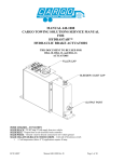
SERVICE MANUAL 440-1015 FOR C ARGO Towing Solutions - Worldwide HYDRAULIC BRAKE ACTUATOR KIT (DOT-3 / DOT-4 BRAKE FLUID) This Document is Applicable to: C ARGO DESCRIPTION Towing Solutions - Worldwide BATTERY PACK IN-CAB CONTROLLER KIT** ACTUATOR KIT 1000 PSI ACTUATOR KIT 1200 PSI ACTUATOR KIT 1600 PSI ** IMPORTANT: This actuator will not function correctly with any other brand or type of brake controller. C ARGO Towing Solutions - Worldwide 11404 Bond Road, Harrison, Ohio 45030 812-655-4544 • Fax 513-202-0079 Website: www.cargobrake.com • Email: [email protected] C ARGO ECN 05157 TowingManual 440-1015F Solutions - Worldwide Page 1 of 14 MANUAL 440-1015 CONTENTS Manual 440-1015TABLE – TableOF of Contents SECTION SECTION A. B. A. B. C. C. D. E. D. F. E. G. F. H. G. I. H. I. J. J. K. K. DESCRIPTION DESCRIPTION Features Features Compatibility Compatability System Components System - Trailer Components Mounted Actuator Important Safety Messages - Trailer Mounted Brake Battery Installation Instructions - Break-Away Switch - In-Cab Wiring Controller Actuator Important InstallationSafety CheckMessages! Procedures Installation Instructions – Trailer Actuator Signal Controller Kit Actuator Wiring DOT Inspection Note Installation Check Procedures Mounting Dimensions/Replacement Parts List DOT Inspection Note Mounting Dimensions / Replacement Parts List Trouble Shooting Guide Trouble Shooting Guide Limited Warranty Cargo Brake Limited Warranty and Limitation of Liability PAGE PAGE 2 2 2 2 2,2 3 34 35 36 47 5 10 6 11 7 12 8 9 13 10 14 11 A, Features: The CARGO BRAKE trailer brake actuator is a microprocessor-based 12 Volt DC system (if using a 24 Volt DC system see Section F. Actuator Wiring – 24 Volt Electrical Wiring Diagram) for use on single, two, and three axle trailers equipped with hydraulic brakes. This unit requires a 17 amp-hour trailer brake “deep cycle” battery and an emergency breakaway switch. CARGO BRAKE recommends a CARGO BRAKE Battery Pack (kit number 304-7131) complete with a 12 VDC, 17 A/H, “deep cycle” battery, enclosure, hardware, and breakaway hardware, breakaway switch,switch. instruction sheet, and straps. The CARGO BRAKE actuator is unique in that it is totally trailer mounted. The actuator connects to the wiring on the trailer and does not require any modifications or additions to the wiring on the tow vehicle. Any vehicle that can connect to the trailer and power the trailer’s lights can make use of the CARGO BRAKE trailer brake actuator. The in-cab controller is provided by a pendant that plugs into the cigarette lighter receptacle (not an accessory power receptacle) on the tow vehicle. No modifications to tow vehicle or to the tow vehicle wiring are required to make the in-cab controller unit operate correctly. Multiple vehicles can share a single in-cab controller by simply moving the in-cab controller from one vehicle to another. Additional in-cab controller units are available and are compatible with all CARGO BRAKE trailer brake actuators. B: Compatibility*: The CARGO BRAKE trailer brake actuator should function properly so long as the towing vehicle can power the running lights and stop lights on the towed trailer. Note that vehicles and trailers that have amber turn signals typically require the use of a tail light converter to insure proper operation. The CARGO BRAKE actuator draws approximately 1 – 3 amps of power from the tail light circuit to power the on-board battery charger. On trailers with multiple running lights, it may be necessary to install a powered tail light converter to insure that adequate power is available to operate the trailer brake actuator. *If a converter is not available, tie the yellow and green wires from the XL to the brake light wire of the towing vehicle. C: System Components: Trailer Mounted Actuator The CARGO BRAKE system is an electric/hydraulic brake actuator, which includes a microprocessor and an accelerometer. The accelerometer is used to sense the amount of braking being generated by the towing vehicle. Based on that input, the microprocessor then automatically adjusts the output of the unit to generate a comparable amount of trailer braking. Unlike a traditional electronic brake control, the electrical power required to actuate the trailer brakes is drawn entirely from the trailer mounted brake battery (“deep cycle”,17-amp hour minimum capacity). To insure that the trailer brake battery remains fully charged at all times, a 3 amp battery charger is included as an integral part of the trailer mounted actuator. Power for that battery charger is drawn ECN 05157 440-1015 Rev F Page 2 ofPage 12 2 of 14 ECN 05157 ManualManual 440-1015F from the running light circuit on the tow vehicle. Thus, it is critical that the tow vehicle running lights are on whenever the trailer is being towed. Note that it is also critical that the trailer brake battery is not connected to any other charging circuit on the tow vehicle. Connecting the trailer brake battery to a second charging source will cause sporadic operation and communication errors between the actuator and in-cab controller. Trailer Mounted Brake Battery All of the power for the trailer brake actuator is drawn from the trailer mounted trailer brake battery. For proper operation, the system needs a “deep cycle” battery with a minimum capacity of 17 amp-hours. Note that the trailer brake battery also provides power to the actuator in the event of an emergency breakaway. Break-Away Switch The system requires an emergency breakaway switch. The breakaway switch is mounted on the trailer and is connected electrically to the trailer brake battery and to the CARGO BRAKE actuator. The switch is also connected mechanically to the tow vehicle. When a breakaway condition occurs, the plunger on the breakaway switch is pulled out by the tow vehicle thereby completing an electrical circuit between the trailer brake battery and the breakaway circuit on the CARGO BRAKE actuator. When the CARGO BRAKE actuator senses a breakaway condition, the trailer brakes are automatically applied at full power. In-Cab Controller C ARGO Towing Solutions - Worldwide STOP– CBRAKE A RGAING OSTATUS Towing Solutions - Worldwide STATUS CODES FLASH RATE CHECK FOR 1 2 3 4 RAPID LOW BATTERY OPEN CIRCUIT SHORT CIRCUIT OVERLOAD TURN LIGHTS ON SEE SERVICE MANUAL MUST OPERATE WITH RUNNING LIGHTS ON The in-cab controller gives the vehicle operator a means to increase or decrease the amount of trailer braking. It also provides both audible and visible indications of any problem detected by the internal monitoring system. The in-cab controller is equipped with colored LEDs to indicate gain setting (green), brake output (red) and system problem status codes (yellow). It also has pushbutton switches to adjust the output of the trailer brakes versus the towing vehicle (i.e. gain) and to manually apply the trailer brakes. The in-cab controller is easily installed by inserting its’ power plug into the cigarette lighter receptacle (not an accessory power receptacle)on the tow vehicle and turning the running lights on. Note that the unit must be plugged in each time that the towing vehicle is started. The unit will automatically check to make sure that the running lights are on and that the system is functioning as designed. In the event that a problem is detected, the unit will flash the yellow status light on the face of the unit and will make a series of audible “beeps”. The number of beeps is an indication of the problem that the system has detected. Count the number of beeps and check the chart on the back of the unit to obtain direction on possible causes of the problem (see Section J. Trouble Shooting Guide). The unit must be unplugged each time the tow vehicle is taken out of service and the running lights are shut off. A series of rapid beeps from the unit is an indication that you either are driving without having your running lights on or that you forgot to unplug the unit when the vehicle was shut off. ECNECN 05157 440-1015 Rev F Page 3 ofPage 12 3 of 14 05157 Manual Manual 440-1015F In-Cab Controller operation is as follows: GAIN SETTING- Press either the UP arrow to increase the amount of trailer braking or the down arrow to decrease the amount of trailer braking. The selected gain level will be shown by the number of green illuminated LED’s on the face of the unit. One light corresponds to the lowest setting, six lights corresponds to the highest gain setting. STOP BUTTON - Press the red square STOP button to manually apply the trailer brakes. Depending on the gain setting selected, 1 to 6 red LED’s will illuminate to indicate the level of braking being generated. The brake lights on the trailer also automatically turn on whenever the manual brake button is depressed. SYSTEM STATUS CODES - Yellow status LED flashes, audible alarm beeps: # Of Beeps or Flashes 1 2 3 4 RAPID Error Indication Low Battery Voltage – trailer brake battery Open Circuit - Internal Components (motor, solenoid). Short Circuit - Internal Components (motor, solenoid). Overload – actuator unit overheated Loss of Power – tail / running lights not turned ON or faulty connection to trailer. D. IMPORTANT SAFETY MESSAGES! WARNING! Thoroughly read and understand this manual before installation. Failure to properly follow this manual could cause a malfunction, resulting in possibly serious or fatal injuries and/or property damage. WARNING! The brake system on the towed vehicle is intended only to supplement the tow vehicle brake system. At no time should the towed vehicle brake system be relied upon to stop the towing vehicle. WARNING! All of the electrical power required to operate the trailer brakes is drawn from the trailer mounted brake battery. It is critical that the trailer brake battery is a “deep cycle” battery and has a minimum capacity of 17 amp hours. Operation with a weak or discharged battery can cause the actuator to malfunction, resulting in possibly serious or fatal injuries and/or property damage. DO NOT ATTEMPT TO OPERATE THE UNIT IF A LOW VOLTAGE CONDITION IS SIGNALED. WARNING! The CARGO TOWING Hydraulic brake actuator is not intended to function as a park brake. When stopped for extended periods of time, apply the towing vehicle park brake and release the brake pedal. WARNING! Failure to properly install, protect, operate and maintain the actuator system can cause a malfunction resulting in possibly serious or fatal injuries and/or property damage. WARNING! The tow vehicle / trailer tail & running lights MUST BE TURNED ON, BEFORE PERFORMING ANY TOWING, for the actuator to operate correctly, and for the breakaway battery to be recharged. Failure to turn the lights ON can cause the actuator to malfunction, or the breakaway battery to become discharged, resulting in possibly serious or fatal injuries and/or property damage. WARNING! Should any SYSTEM PROBLEM STATUS CODE signals occur, immediately stop the tow vehicle / trailer and make all necessary repairs (see Section J. Trouble Shooting Guide). Failure to properly maintain the actuator system can result in possibly serious or fatal injuries and/or property damage. 05157Manual 440-1015 Manual 440-1015F Page 4 of 14 ECNECN 05157 Rev F Page 4 of 12 D. Installation Instructions – Trailer Actuator: Before Starting 1. The following materials are required to properly install the Hydrastar XL unit: • If your trailer is not already equipped with brake lines, you will need enough 3/16 inch diameter automotive brake line to connect the trailer brakes to the Hydrastar XL unit. (Note that ¼ inch diameter brake line is recommended for 3 axle trailers or for trailers where the total brake line length exceeds 25 feet). Where possible, steel tubing is preferred. • 4 pieces of #10 mounting hardware to mount the Hydrastar XL unit to the trailer. • 1 quart of DOT 3 or DOT 4 brake fluid (from a new, sealed container). • 1 emergency breakaway kit. The emergency breakaway kit must include a 12 VDC, 17 A/H, “deep cycle” battery (minimum). • Wire (See Section F. Actuator Wiring for proper wire size.) 2. Flush existing brake system and lines with mineral spirits (not mineral oil), DOT 3 or DOT 4 brake fluid prior to connecting the Hydrastar XL unit. 3. Examine all trailer brakes and associated brake lines and fittings to assure they are in good condition. Repair any leaks and replace worn or damaged brake lines, shoes or pads. 4. Inspect the trailer brakes to be sure they are properly adjusted. Consult your trailer owner’s manual for instructions on how to adjust the trailer brakes. 5. The Hydrastar XL unit contains sensitive electronics that must be protected. Drilling additional holes in the housing or electrostatically painting the Hydrastar XL unit, or welding anywhere on the Hydrastar XL unit will damage the unit making it inoperable and will void the manufacturer’s warranty. Always remove the Hydrastar XL from the trailer before doing any welding repair or modifications to the trailer structure. Mounting the Trailer Brake Actuator, Trailer Brake Battery, and Emergency Breakaway Switch 1. Position the trailer as if it were connected to the towing vehicle. The actuator must be installed at a location on the trailer that is level to insure proper operation. Failure to properly level the unit may result in sporadic operation. 2. Select a mounting area for the actuator on the trailer that will provide easy access to the trailer brake battery, the emergency breakaway switch, and the trailer / tow vehicle electrical connector. The mounting location should give consideration to protecting the unit from road debris and from unnecessary abuse (I.e. The unit should not be used as a step). 3. The long side of the actuator must be mounted parallel to the trailer centerline so that the wiring is directed to the front of the trailer. Failure to properly align the unit may result in sporadic operation. 4. The actuator must be mounted in a horizontal position with the filler cap up. MUST BE PARALLEL TRAILER CENTERLINE ACTUATOR 5. Attach the actuator to the trailer by installing four (4) #10 screws through the mounting holes. 6. The trailer brake battery can be mounted at any convenient location on the trailer. Mount the battery enclosure with (2) 0.25 inch diameter screws to trailer giving consideration to the fact that the battery is heavy and requires adequate support. 7. Mount the emergency breakaway switch on the tongue of the trailer providing for a direct mechanical link between the switch plunger and the towing vehicle. Mount the switch with a 0.25-inch screw. 8. Remove the red plastic plug from the brake port on the actuator, exposing a 3/16 inch inverted flare fitting. Connect the brake line from the trailer to this fitting. ECN05157 05157 ECN Manual 440-1015F Manual 440-1015 Rev F Page 5Page of 125 of 14 9. Fill the actuator reservoir with DOT 3 or DOT 4 brake fluid, and replace the cap. CAUTION: Always refill with new brake fluid from a sealed container. Never reuse old or dirty brake fluid. Clean off any brake fluid that may have been spilled on the trailer or actuator unit. E. Actuator Wiring: Connect the six wires from the trailer-mounted actuator to the trailer wiring system as follows – See Diagram NOTE: Trailer wiring to the actuator must be 14 gauge or larger wires. WARNING! Failure to wire the unit properly can result in damage to the trailer brake actuator. Trailer Actuator Wires BROWN WIRE Connect the brown wire from the actuator to the tail light / running light circuit on the trailer. YELLOW WIRE - Connect the yellow wire from the actuator to the left turn signal / brake light circuit on the trailer. GREEN WIRE - Connect the green wire from the actuator to the right turn signal / brake light circuit on the trailer. WHITE WIRE - Connect the white wire from the actuator to the negative terminal ( - ) on the trailer battery and to both a ground connection on the trailer and to the ground wire in the wiring harness from the tow vehicle. The unit will not operate properly without a direct connection to the ground circuit on the towing vehicle. Grounding between the trailer ball and coupler without a direct connection to the towing vehicle ground circuit will result in system errors. BLACK WIRE - Connect the black wire from the actuator to the positive terminal ( + ) on the trailer battery and to one side of the emergency breakaway switch. BLUE WIRE - Connect the blue wire from the actuator only to the remaining unused emergency break away switch terminal. IT MUST NOT BE CONNECTED TO ANY OTHER CIRCUIT. 12 Volt Electrical Wiring Diagram: LH TURN SIGNAL YELLOW RH TURN SIGNAL GREEN BRAKES BRAKE LINES ACTUATOR CIRCUITS: TAIL LIGHTS - BROWN LH TURN SIGNAL - YELLOW RH TURN SIGNAL - GREEN BLACK TAIL LIGHTS BROWN TRAILER BREAKAWAY SWITCH BLUE TOW VEHICLE NEGATIVE GROUND WHITE NEGATIVE GROUND - WHITE BRAKE BATTERY BRAKES NOTE: DISCONNECT ANY BRAKE CONTROLLER INSTALLED IN THE TOW VEHICLE. IT IS BEST TO USE A CONVERTER PIG TAIL WHICH WILL KEEP ANY BRAKE CONTROLLER SIGNAL FROM INTERFACING WITH THE XL SYSTEM, I.E., A SEVEN RV PLUG CONVERTED TO A 4 WIRE FLAT SYSTEM. ECNECN 05157 440-1015 Rev F Page 6 ofPage 12 6 of 14 05157 ManualManual 440-1015F WHITE BATTERY * = CUSTOMER SUPPLIED BRAKES NOTE: DISCONNECT ANY BRAKE CONTROLLER INSTALLED IN THE TOW VEHICLE OR CONVERT TO A FOUR WIRE FLAT PLUG. NOTE: DISCONNECT ANY BRAKE CONTROLLER INSTALLED IN THE TOW VEHICLE. F. Installation Check Procedures: Checks With Tow Vehicle Engine NOT RUNNING, Park Brake SET, In-Cab Controller Unplugged1. 1. Turn on on the thetow towvehicle vehiclerunning runninglight lightswitch. switch.(SEE (SEE FOLLOWING NOTE) Verify the trailer running Turn FOLLOWING NOTE) Verify that that the trailer running lightslights are ON, ON, and andthat thatpower powerisisbeing beingsupplied suppliedtotothe theBROWN BROWN wire CARLISLE actuator. any are wire onon thethe CTS actuator. Make any Make necessary necessary repairs. repairs. 2. Apply and release the tow vehicle brake pedal several times. Each time the pedal is pressed the brake lights on both the tow vehicle and trailer should be illuminated, and power should be supplied to both the yellow and green wires on the actuator. Make any necessary repairs. 3. Turn OFF the tow vehicle tail / running light switch. Activate the breakaway system by pulling out the breakaway switch plunger. Verify that power is being supplied to the blue wire on the actuator, and that the trailer brakes are functioning correctly. Replace the plunger on the emergency breakaway switch. NOTE: For Trailers with multiple tail/running lights, the tow vehicle may require a Power Taillight Converter to avoid blown fuses. Vehicles with separate brake and turn signal (amber) Lights will also require a converter. In-Cab Controller Operation 1. With the tail/running light switch OFF, plug the in-cab controller cord into the cigarette lighter receptacle (not an accessory power receptacle). A “beeping” sound should be heard, and the in-cab controller should display a rapidly flashing yellow light. Turn on the light switch – the sound and flashing light should stop. If it continues to sound and flash, recheck for 12 volts to the BROWN wire, and/or for correct GROUND circuit wiring. 2. Repeatedly press the UP or DOWN arrow switches on the controller. From 1 to 6 green LED indicators should glow to indicate that various gain settings are being selected. 3. Select maximum gain setting (6 green LED), press and hold the square, red STOP switch. From 3 to 6 red LED indicators on the in-cab controller should glow, and the trailer brake lights should be illuminated. 4. Apply and release the tow vehicle brake pedal several times. Each time the pedal is pressed, from 1 to 3 ECN 05157 440-1015 Revlights F red LED indicators should glow, andManual the trailer brake should illuminate. Page 7 of 12 ECN 05157 Manual 440-1015F Page 7 of 14 FOR UNITS WHICH CANNOT COMMUNICATE WITH THE ACTUATOR IN SOME TOW VEHICLES, OR VEHICLES WITH 24 VOLT ELECTRICAL SYSTEMS NOTE: THE TRAILER MUST BE WIRED FOR 12 VOLTS FOR LIGHTS. THE CIGRETTE LIGHTER RECEPTACLE MUST ALSO BE WIRED FOR 12 VOLTS. IN-CAB CONTROLLER WIRED FOR 12 VOLTS DC CIGARETTE LIGHTER RECEPTACLE (12 VDC REQ.) 12V + CONNECT TO TOW VEHICLE RUNNING LIGHT 12 VOLT FUSE BLOCK IN TOWING VEHICLE SIGNAL COUPLER SUPPLIED BY CARGO TOWING SOLUTIONS NOTE: USE CARGO TOWING SOLUTIONS SIGNAL COUPLER FOR 24V SYSTEMS OR 12V SYSTEMS WHEN CONTROLLER WILL NOT COMMUNICATE WITH THE TOW VEHICLE. ATTACH THE SIGNAL COUPLER TO THE POSITIVE + WIRE ON THE 12V RECEPTACLE IN THE TOW VEHICLE AND RUN THE OTHER END OF THE WIRE TO THE FUSE BLOCK FOR THE 12V RUNNING LIGHTS ON THE VEHICLE. ECN 05157 Manual 440-1015F Page 8 of 14 WIRING SCHEMATIC FOR TOW VEHICLES WITH AIR BRAKES OR VEHICLES HAVING NO DIRECTIONAL SIGNALS WIRING INSTRUCTIONS FOR TOWING VEHICLES WITH AIR BRAKES OR SEPARATE AMBER TURN SIGNAL LIGHTS, OR NO TURN SIGNAL LIGHTS Splice the brake light wires (or brake switch wire) from the tow vehicle to the yellow and green wires coming from the ElectraStar/HydraStar XL. It will be necessary to splice the directional light wires from the tow vehicle to the trailer directional lilghts. RUNNING LIGHTS RUNNING LIGHTS - BROWN BRAKE LIGHT SWITCH RIGHT TURN SIGNAL LEFT TURN SIGNAL TO RIGHT TURN SIGNAL LIGHT TO LEFT TURN SIGNAL LIGHT NOTE: DISCONNECT ANY BRAKE CONTROLLER INSTALLED IN THE TOW VEHICLE. ECN 05157 Manual 440-1015F Page 9 of 14 C AR GO Controller Signal Coupler Kit G. The controller signal coupler kit is used when the controller cannot “communicate with the CTS systems’ brake actuator”. To determine if the harness is required, connect the unit according to the instructions in the owner’s manual. If the controller constantly beeps with the towing vehicle lights turned on, the vehicles electrical system may be filtering and weakening the RF signal in the controller. If this occurs, install the signal coupler supplied with the unit according to the instruction sheet. If there is a rental situation where there are numerous towing vehicles involved, the umbilical cord may be a better solution. Obtain an umbilical cord harness from CTS. PART NUMBER: 304-7160 Step 1 - Run the (+) wire direct from the socket to the 12 V DC fuse block of the towing vehicle. (See Wiring Diagram) Step 2 - Ground the socket to the towing vehicle. Step 3 - Test the controller to see if the settings can be changed. If the controller “beeps” constantly with the lights on. Use the umbilical cord option. (See Figure 1) WIRE TO (+) WIRE on 12 V DC SOCKET WIRE DIRECT TO 12 V DC FUSE BLOCK OF TOWING VEHICLE FIGURE 1 Signal Coupler NOTE: Use either wire end of Signal Coupler SIGNAL COUPLER VEHICLE 12 V DC SOCKET (+) (-) GROUND ANYWHERE ON TOWING VEHICLE WIRE DIRECT TO 12 V DC FUSE BLOCK OF TOWING VEHICLE 11404 Bond Rd. Harrison, OH 45030 I Call 812-655-4544 I www.cargobrake.com © Copyright 2014 - CTS WORLDWIDE All Rights Reserved ECN 05157 Manual 440-1015F Page 10 of 14 4. Apply and release the tow vehicle brake pedal several times. Each time the pedal is pressed, from 1 to 3 red LED indicators should glow, and the trailer brake lights should illuminate. Bleeding the Brakes1. Obtain needed materials- Plastic tubing, inside diameter to fit bleed fitting snugly. Clear, clean container Brake Fluid, DOT 3 or DOT 4, from new container 2. Block the wheels of the trailer and tow vehicle. 3. Starting at the rearmost trailer axle, open the bleed fitting one half (1/2) turn on the brake farthest from the actuator unit. 4. Attach one end of the plastic tubing onto the bleed fitting, and immerse the other end in a clear container partially filled with brake fluid. 5. Turn on the tow vehicle tail/running light switch, select the maximum gain setting, then activate the actuator unit by applying and holding the red button on the in-cab controller. 6. Observe the tube end in the container for air bubbles escaping, and continue until no more bubbles are emitted into the container. 7. Tighten the bleed fitting securely. Release the red button on the in-cab controller, and remove the plastic tubing. 8. CAUTION: During bleeding, periodically check and replace the fluid in the reservoir. Running the unit without adequate brake fluid will cause permanent damage. Repeat Steps 3 through 6 for each brake on the trailer. Checks with Tow Vehicle Engine Running – USE EXTREME CAUTION! 1. Select the maximum gain setting (6 Green LED) using the in-cab controller. Apply and HOLD the red button on the in-cab controller, release the park brake, start the engine and place the transmission shift lever in Forward. With the engine at low idle speed, release the brake pedal enough to allow the tow vehicle to move slowly forward. Apply a small force to the brake pedal. The trailer brakes should be felt to apply, noticeably slowing the tow vehicle. Repeat this procedure 2-3 more times. 2. Lower the gain setting to number 5 and perform Check Procedure 8 several more times, trying various levels of applied pedal force. 3. Continue checking at various gain setting steps until you are thoroughly experienced at operating the system, and have established the appropriate gain setting for the particular trailer involved. G. DOT DOTinspection InspectionNote: Note: H. To demonstrate that the actuator and trailer brake system are functioning properly, adjust the up arrow on the cab controller until the system is set at its maximum gain setting (i.e. 6 green LED’s illuminated). Press and hold the red STOP button on the in-cab controller and attempt to drive through the trailer brakes. This will apply the maximum power to the trailer brakes and will demonstrate to DOT personnel that the trailer brakes are functioning properly. ECN 05157 ECN 05157 Manual 440-1015 Rev F Manual 440-1015F Page 8 of 12 Page 11 of 14 H. Mounting Mounting Dimensions Dimensions / Replacement Parts List: I. (16.50) (15.70) GASKET GASKET MANIFOLD WARNING USE D.O.T. 3 OR D.O.T. 4 BRAKE FLUID FROM A NEW SEALED CONTAINER 4.85 OUTPUT PRESSURE____ VERIFIED BY_____ (5.35) 2.88 (3.38) FILLER CAP 3 4X Ø .213 MOUNTING HOLES (14.39) OUTPUT PORT 1 (5.65) REPLACEMENT PARTS LIST ITEM PART NUMBER QTY 1 192-7089 1 1 304-7107 1 1 1 3 68-8641 68-8728 32-7640 1 1 Not Shown 381-7022 1 Not Shown 304-7131 1 Not Shown 304-7160 1 DESCRIPTION OUTPUT PORT ADAPTER ASSEMBLY 3/16 INCH INVERTED FLARE OUTPUT PORT ADAPTER ASSEMBLY 1/4 INCH INVERTED FLARE KIT GASKET MANIFOLD SIDE GASKET END PLATE SIDE FILLER CAP PARTS KIT, REPLACEMENT IN-CAB CONTROLLER TRAILER BATTERY PACK COMPLETE: 12 VDC, 17 A/H, DEEP CYCLE BATTERY, ENCLOSURE, HARDWARE, BREAKAWAY SWITCH, INSTRUCTION SHEET, AND STRAPS SIGNAL COUPLER ECN 05157 440-1015 Rev F Page 9 of 12 12 of 14 ECN 05157 Manual Manual 440-1015F Page J . Trouble Shooting Guide Controller beeps one time, repeatedly. • Low Battery: Check for low battery by pulling breakaway pin. Voltage should drop from 12 volts DC to 10-11 volts DC. If drop is larger, charge or replace battery. Controller beeps two times, repeatedly. • Open Circuit: Pull breakaway pin. Make sure brakes are working. If not, check for loose or broken connections. Controller beeps three times, repeatedly. • Short Circuit: Check for bare wire or loose connections in ground. Also check for power wires making contact with each other or grounded surface. Controller beeps four times, repeatedly. • Overload: Check for too many running lights, or too many axles (more than three heavy duty). Controller beeps five times, repeatedly. Turn Lights On: • Make sure that the trailer running lights are on. • Make sure the in-cab controller is plugged into the cigarette lighter receptacle (not an accessory power receptacle). • Check for bad connections in plugs on the trailer and towing vehicle. • Make sure plug pins are tight and not worn from use or dragging on the ground. • Make sure there is no corrosion. Check ground connections. Make sure trailer is grounded to towing vehicle and trailer battery. Brakes are not aggressive enough (all green lights are illuminated). • Make sure brake system is bled properly. (see Section G. Installation Check Procedures / Bleeding the Brakes) • If drum brakes, adjust brakes. • Loosen or remove attaching bolts. Remount the unit with the rear end of the Hydrastar XL elevated approximately 2 inches. Unit is not putting out pressure. • Make sure brake system is bled properly. (see Section G. Installation Check Procedures / Bleeding the Brakes) • With no power to the unit, remove the filler cap. Place a finger in the reservoir. A screened tube, fixed in place, should be felt. If this tube is not felt, or it moves around, the unit needs repaired. • Remove the attaching bolts. Have a second person depress the brake pedal on the towing vehicle, and hold it down. Have a second person slowly lift the rear end of the Hydrastar XL unit. The pitch of the motor should change as the unit is lifted higher and higher. If this does not occur, the unit need repaired. Brakes do not apply when pressing on the brake pedal, and vehicle and trailer are not moving. • When the vehicle and trailer are not moving, the brakes will not activate when you press on the brake pedal. Raise the gain setting until all six green lights are illuminated. Apply and HOLD the red button on the in-cab controller. All red lights will come on for an instant and then drop to one to three red lights. Trailer “jerks” when brakes are first applied. • Turn gain setting down, so fewer green lights are illuminated. • If the trailer has drum brakes, back off of the brake adjustment slightly on all trailer wheels. Trailer lights flicker. • Battery charger in the Hydrastar XL is cycling on and off. This may be eliminated by running a brown wire directly from the trailer plug to the brown wire on the Hydrastar XL unit. ECN 05157 440-1015 Rev F Page 10Page of 1213 of 14 ECN 05157 Manual Manual 440-1015F C ARGO Towing Solutions - Worldwide K. LIMITED WARRANTY and LIMITATION OF LIABILITY Brake Actuators manufactured and sold by Cargo Towing Solutions are warranted to be free from defects in material and workmanship when properly installed, used and maintained under normal and proper use for a period of: (2) two years from date of delivery to the original purchaser vehicle in-service date subsequent to installation of Cargo Towing Solutions’ brake actuator products, or (2) two years from purchase date of a free standing unit. No claim for breach of warranty will be allowed unless the party making the claim is the original purchaser of the brake actuator, the Buyer promptly notified Cargo Towing Solutions Towing Solutions - Worldwide during the warranty period of the claimed material or workmanship defect is found within the warranty period, properly documented by buyer and CARGO TOWING SOLUTIONS is notified in writing within 30 days from failure and provides Cargo Towing Solutions with the Serial Number and any substantiation which may include, but is not limited to, the return of the Product and any other information which Cargo Towing Solutions may reasonably request. C ARGO This warranty shall not apply to any damage or lost cause by any or all of the following circumstances or conditions: • Damage caused during installation; • Parts, accessories, materials or components which have not been approved by Cargo Towing Solutions; • Misapplication, misuse, or failure to following the directions or observe the cautions and warnings on installation, operation, application, inspection, or maintenance specified in any Cargo Towing Solutions’ “sales literature, specific action sheet, service manual or other applicable literature”; or • products altered or utilized in a manner not approved by Cargo Towing Solutions or subjected to abuse, misuse, improper maintenance, negligence or accident. THE FOREGOING WARRANTIES ARE EXCLUSIVE, AND ARE ACCEPTED BY BUYER IN LIEU OF ANY AND ALL OTHER WARRANTIES, EXPRESSED OR IMPLIED, INCLUDING WITHOUT LIMITATION THE IMPLIED WARRANTIES OF MERCHANTABILITY OR FITNESS FOR PARTICULAR PURPOSE. Buyer’s sole remedy in the event of a breach of the foregoing warranties is the repair or replacement of the affected product by Cargo Towing Solutions as determined by it in its sole discretion. NO merchandise will be accepted for warranty credit consideration without a Returned Goods Authorization Number issued by the Customer Service Representative (812-655-4544). If, upon inspection by the Returned Goods Technician, the merchandise is found to be free from defects in material and workmanship, then the warranty claim shall be deemed invalid, and the merchandise shall be held for a period of (15) days pending disposition by the buyer and an inspection charge may be applied by Cargo Towing Solutions. BUYER AGREES THAT IN NO EVENT WILL CARGO TOWING SOLUTIONS’ LIABILITY FOR ALL LOSSES FROM ANY CAUSE, WHETHER BASED ON CONTRACT, NEGLIGENCE, STRICT LIABILITY, OTHER TORT OR OTHERWISE, EXCEED BUYER'S NET PURCHASE PRICE, NOR WILL CARLISLE CARGO TOWING SOLUTIONS BE LIABLE FOR ANY SPECIAL, INCIDENTAL, CONSEQUENTIAL OR EXEMPLARY DAMAGES. The foregoing warranties will continue in effect so long as the product is serviced and maintained in accordance with Cargo Towing Solutions’ instructions and with genuine Cargo Towing Solutions’ manufactured replacement parts. These warranties may not be altered or amended except by a written instrument signed by buyer and a duly authorized officer of Cargo Towing Solutions. Any claim not made in compliance with this limited warranty shall conclusively be deemed waived. ECN 05157 Manual 440-1015F Page 14 of 14