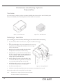
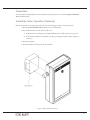
1
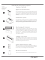
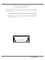
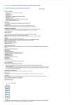
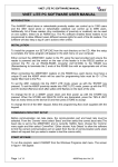
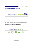
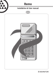
CA9120 Wanderer Monitoring System Inservice Manual with Policy and Procedure Suggestions CA9120 Inservice Manual Released 9/3/99 0510-0018-E Copyright 1999 by Code Alert® All rights reserved. No part of this work may be reproduced or copied in any form or by any means without written permission from Code Alert® The following are policy and procedure suggestions from Code Alert. Because each facility is unique, your facility should develop a formal policy and procedure and implement it prior to your system start-up. 3125 N. 126th Street • Brookfield, Wisconsin 53005 (262) 790 -1771 • 1-800-669-9946 • FAX (262) 790-1784 www.codealert.com Contacts: In-house (ie. maintenance): ______________________________________ Nursing: _________________________________________________________ List of Equipment and Door System locations: 3 Wanderer Monitoring System Table of Contents List of Figures ................................................................................................................................................ 5 CA9120 Overview ......................................................................................................................................... 6 Overview ................................................................................................................................................... 6 CA9120 Control Unit ................................................................................................................................... 7 Overview ................................................................................................................................................... 7 Functions ................................................................................................................................................... 7 Indicators ................................................................................................................................................... 7 Responding to System Alarm ..........................................................................................................................................8 Bypassing the System ........................................................................................................................................................9 Transmitter .................................................................................................................................................. 10 Overview ................................................................................................................................................. 10 Fastening a transmitter .............................................................................................................................. 10 Transmitter Tester ........................................................................................................................................ 11 Transmitters .............................................................................................................................................. 11 Transmitter Tester Operation (Optional) .................................................................................................... 11 System Options ............................................................................................................................................ 12 Sample Policy and Procedures .......................................................................................................................................13 Wanderer Monitoring System Tips and Reminders ....................................................................................................14 Product Warranty ....................................................................................................................................... 15 4 Wanderer Monitoring System List of Figures Figure 1: Wanderer Monitoring System Overview .............................................................................................. 6 Figure 2: CA9120 Control Unit ........................................................................................................................ 7 Figure 3: 3 - Year Transmitter ............................................................................................................................ 10 Figure 4: 1.5 - Year Transmitter ......................................................................................................................... 10 Figure 5: Fastening the Band ........................................................................................................................... 10 Figure 6: Optional Transmitter Tester ............................................................................................................... 11 5 Wanderer Monitoring System CA9120 Overview Overview Your Code Alert® CA9120 Wanderer Monitoring System was designed to meet the specific needs of your facility. Code Alert provides you with a reliable system for protecting residents and patients who tend to wander. The lightweight resident worn transmitter is the center of your system. When a resident or patient wearing a transmitter enters a monitored zone, the transmitter's signal is received by the receiver which is then sent on to the control unit for decoding to determine an alarm condition. When the resident opens the monitored door, the control unit sounds an alarm and activates other remotely installed options. Only a resident or patient wearing a transmitter activates the alarm; everyone else can move freely through the monitored zone. Note: If a resident wearing a transmitter is near an exit protected by the system and someone not wearing a transmitter opens the door, the Control Unit may alarm. Magnetic Reed Switch ê CA9120 Receiver è ç CA9120 Control Unit Transmitter ì ç Figure 1: Wanderer Monitoring System Overview 6 CA9120 Receiver Wanderer Monitoring System CA9120 Control Unit The primary electronics for the CA9120 are housed within a durable metallic enclosure that is conveniently mounted near the doorway, hallway or elevator to be monitored. The control unit has a pleasing, unassuming appearance that also contains the audio alarm and the keypad. The control unit has a keypad which is used to reset the system following an alarm. Staff may also use the keypad to bypass the system long enough to escort a resident/patient through the monitored zone without setting off the alarm. When the time allotted for bypass has elapsed or the door closes behind the staff member, the system automatically resets itself. The control unit has three indicator lights. When the red light is on, the system is active. The yellow signal light indicates when electronic interference or noise is in the area. When the green light is on, the system is disarmed, allowing bypass for a preset amount of seconds (15, 30, 45, 60). The system will automatically re-arm itself when the bypass time has expired or the door is closed after exiting. Functions Staffs use of the CA9120 Control Unit: l Reset of alarms. l Bypass of alarms . Red Yellow Green AC TIV E SIG NA L STA TU S Indicators Your CA9120 control unit has the following indicators: l POWER - Red LED which indicates power is available to the system. Mo l SIGNAL - Yellow LED which indicates that the control unit has received a signal from the receivers, ie. resident worn transmitter or noise interference. l STATUS - Green LED indicating the current status of nit ori ng Sys tem Figure 2: CA9120 Control Unit bypass. If unit is in bypass the green LED will be lit. Weekly Testing of the Code Alert Door System: The Code Alert System should be checked at a minimum on a weekly basis for proper operation. I.E. Red light on the control unit is on, when bypass code is entered, green light is on. An extra transmitter should be designated for the sole use of testing. Transmitter should be brought to the area, check and make sure that yellow light flashes. Attempt to open door. The alarm should sound. Enter reset code. A documented log book should be kept of these testings. 7 Responding to a System Alarm: A tone sounds at door location of alarm and at remote locations (optional) 1. 2. 3. 4. 5. Calmly proceed to location of alarm. Locate wandering resident Bring resident into “safe zone.” Discreetly enter reset code into keypad. Document incident in log book, including resident name, responders name, alarm location, date, time, etc. Important: Keep your Code Alert reset and bypass codes confidential Your default reset code is 1 3 7 9 NOTE: Your reset/bypass codes may have been changed from their original defaults. Please consult your maintenance or supervisory staff for more information. 8 Bypassing of System: The purpose of the bypass function is to be able to escort a resident through a monitored door without having the system alarm. 1. 2. 3. 4. Discreetly enter bypass code outside of view of the wandering resident. Proceed through door area and make sure to close door. When wanting to come back through opposite side, press bypass button or enter bypass code into keypad located on the opposite side of the door. Your system will automatically reset after you pass through the door. The bypass time is factory preset for 15 seconds. If you find this amount of time inadequate, contact your in house person responsible for the maintenance of the system. Any problems with the system should be documented in your log book. If you believe you are experiencing some difficulty with your system, call Code Alert’s Technical Department immediately (1-800-669-9946). If you are unable to call immediately, document the date, time, and details of the incident and call as soon as possible. Important: Keep your Code Alert reset and bypass codes confidential To bypass Code Alert, press 1 + # at the same time NOTE: Your reset/bypass codes may have been changed from their original defaults. Please consult your maintenance or supervisory staff for more information. 9 Wanderer Monitoring System Transmitter Overview Upon assessment of a wandering resident, a transmitter should be placed on the resident. Your Code Alert system allows you the flexibility of wrist and ankle placement of the resident worn transmitter. Figure 3: 3 - Year Transmitter Figure 4: 1.5 - Year Transmitter Fastening a transmitter Upon determing placement of transmitter, the following directions should be followed for fastening. 1. Test the transmitter with the transmitter tester. ( Use photo and directions from page 11) 2. Insert the band through the slot on the transmitter from bottom to top and pull the band over the top of the transmitter and down through the slot on the other side. 3 Bring the band around the wrist/ankle so that the end with the adjustment holes meets the end with the snap. 4. Adjust the band to a position where the transmitter will not slip off, yet is loose enough to provide comfort for the resident. CAUTION - Place the ankle transmitter loose enough to prevent possible ankle edema. 5. Once the adjustment is made, slip the selected hole down onto the wide collar of the snap. Bend the excess band back over so the next hole also slips down onto the collar. 6. Fold the flap with the snap peg over onto the band and into the collar and squeeze the two securely together. 7. Cut off excess band with scissors. 8. Code Alert recommends testing of the resident worn transmitters at a minimum of once a week. This procedure will provide a secure and safe fit on the resident. Note: *Transmitters are waterproof and can be worn at all times. *To remove transmitter, cut band with scissors. 10 Figure 5: Fastening the Band Transmitters To test a transmitter, simply walk the monitored resident through a detection zone or use the the Optional Transmitter Tester as indicated below. Transmitter Tester Operation (Optional) Place the transmitter on a resident/patient please, then use the following procedure to test the transmitter: 1. Place the optional Transmitter Tester directly on top of the transmitter. 2. Press and hold the button on the left side of the tester. A. If the transmitter is working, the green light will blink and a tone will sound once every second. B. If the transmitter fails this test, check the tester battery and replace if required. Tester requires one 9V battery. 3. Retest the transmitter. 4. If transmitter fails a second time, replace the transmitter. Tra nsm r itte Tes ter Figure 6: Optional Transmitter Tester 11 Wanderer Monitoring System System Options Check off if included on packing list. The items checked are part of your system. Eight Zone Staff Alert Panel If your Code Alert detection zones are not located within sight and sound of the nurse's station, it's likely that a staff alert panel has been installed at the nurse's station. The Staff Alert Panel informs staff personnel of possible wandering events and their location, much like the control unit at the detection zone does. AC TIV E SA 10 0S ta ff Identification System Ide nti fic ati on Co nso If a resident leaves a monitored zone, the zone number and transmitter identification number are displayed on the Identification Console. This identifies alarm events by giving transmitter identification, alarm location, as well as optional hard copy printout with date and time for your records. le Electromagnetic CodeLock The electromagnetic CodeLock™ door lock automatically activates when a resident wearing a transmitter enters the detection zone. The door remains locked with a holding force of 1,500 lbs. until the individual is no longer in range of the door. CodeLock meets all NFPA® 101 Life Safety Code requirements. A separate manual is provided with the purchase of electromagnetic CodeLocks. CA3000 Voice Alarm C A3 00 0 Vo ic e Al ar m The CA3000™ Voice Alarm provides an immediate verbal announcement whenever an alarm event occurs. This notification is sent over the existing public address system or at a nurses' station. The announcement is instantaneous and identifies the specific location of the event. Passive Infrared Detector (PIR) PIR's may be used in place of the magnetic reed switches in hallways. It prevents the alarm from occurring unless an individual wearing a transmitter is near the security zone and in the path of the beam from the PIR. Elevator Deactivation This option prevents the elevator door from closing during an alarm event. 12 Sample Policy and Procedures The following are policy and procedure suggestions from Code Alert. Because each facility is unique, a formal policy and procedure should be designed and implemented prior to your system start-up. Review Inservice Manual with Installer Be certain that all staff members and new staff members are trained on the proper use of the Wanderer Monitoring System. Refresher training is recommended every 6 months. Designate an in-house staff member as the trainer. This trainer is responsible for the keeping of this in-service manual and facilitating training sessions. Designate an in-house staff member as the Code Alert System Tester. They will be responsible for the routine weekly testing of each door system and will be responsible for communicating any changes with the system with other staff members. This includes the changing of the reset codes, bypass codes, and bypass times. This contact should be responsible for the keeping of the Code Alert Installation Manual and creating a system log book. (A copy of page 7 should be included.) Each admission is to have a wandering assessment. Designate the responsible staff member for this assessment. If admission is found to be at risk, they are to be outfitted with a transmitter. Transmitter Testing: A nursing staff member is to be assigned to do this task on a weekly basis. See page 11 for instructions. The transmitter band should also be checked for excessive wear and tear. If damaged, replace the band immediately. Again, all testing should be documented in a log book. (A copy of page 11 should be given) A list should be created of all residents wearing transmitters. Any changes to this list should be communicated with all staff members. This should be kept in transmitter log book. Make sure all staff members know who is responsible for responding to system alarms and what their role is. Those responsible should be given a copy of page 8. Designate staff members who are able to bypass system for escorting of wandering residents. Those responsible should be given a copy of page 9. Two extra transmitters should be on hand as spares, if needed, extra transmitters can be ordered by calling, 1800-669-9946 and ask for Customer Service. When calling have your customer number and the part numbers needing ready or fax your order in to 1-800-366-9946. Note: These are sample policy and procedures. We recommend at least a weekly test. However, many facilities test daily or at shift changes. 13 Wanderer Monitoring System Tips and reminders It is important that there be two or more staff members (possibly an administrator or a maintenance person) appointed to ensure proper use and operation of the Wanderer Monitoring System, and to document any necessary information your facility may need to keep. l Be certain that all staff members and new staff members are trained on the proper use of the Wanderer Monitoring System. Reading the in-service manual is important in familiarizing staff with the system. l If you believe you are experiencing some difficulty with the system, call our Technical Department immediately (1-800-669-9946). If you are unable to call immediately, document the date, time and details of the incident and call us as soon as possible. Having difficulties with your Code Alert System? Call 1-800-669-9946 14 Wanderer Monitoring System Product Warranty Code Alert, Inc. (herein referred to as “Seller”) warrants to the Buyer that the Code Alert System (herein referred to as “Product”) will be free from defects in material and workmanship for a period of one (1) year from date of sale and title, and will conform to the Seller’s quotation. Transmitter battery life varies from one (1) to three (3) years depending upon specific design, as quoted for sale. Transponder battery life is warranted for three (3) years. Battery is covered by a limited warranty prorated over the life of the battery. This warranty only applies to battery life and does not include back-plates, casings or bands which is one (1) year as stated elsewhere in this product warranty statement. Seller’s obligation under this warranty shall be limited to repairing or replacing any part which, within one (1) year from the date of sale, is returned to the factory, shipment prepaid, and upon examination by Seller, shall disclose to have been defective. The criteria for all testing shall be Seller’s applicable product specifications utilizing factory specified calibration and test procedures and instruments. No allowance shall be made for local repair bills or expenses without the prior written approval of Seller. Warranty coverage does not include any defect or performance deficiency (including failure to conform to product descriptions or specifications) which results, in whole or in part, from (1) improper storage or handling of the Product by Buyer, its employees, agents or contractors, (2) absence of any product, component or accessory recommended by Seller, but omitted at Buyer’s direction, (3) any design, specification or instruction changed by Buyer, its employees, agents or contractors, (4) failure to comply with any applicable instructions or recommendations of Seller, including installation procedures, (5) physical damage occurring to transponders or other components after receipt and acceptance by buyer, or (6) acts of God, acts of civil or military authority, fires, floods, strikes, or other labor disturbances, war, riot, or other causes beyond the reasonable control of the Seller. The preceding paragraphs set forth Buyer’s exclusive remedies and Seller’s sole liability for claims based on the failure of the products to meet any warranty, whether the claim is in contract, warranty, tort, (including negligence and strict liability) or otherwise, and however instituted, and upon the expiration of the applicable warranty period of such liability shall terminate. IN NO EVENT SHALL SELLER BE LIABLE FOR SPECIAL OR CONSEQUENTIAL DAMAGES. THIS WARRANTY IS THE ONLY WARRANTY APPLICABLE TO THE PRODUCT AND IS IN LIEU OF ANY OTHER WARRANTIES, EXPRESSED OR IMPLIED, INCLUDING ANY IMPLIED WARRANTY OF MERCHANTABILITY OR FITNESS FOR A PARTICULAR PURPOSE. 15 3125 N. 126th Street Brookfield, Wisconsin 53005 1-800-669-9946 • FAX (262) 790-1784 www.codealert.com