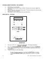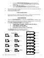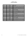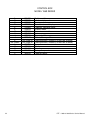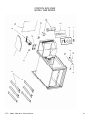
1
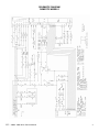
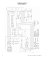
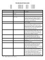
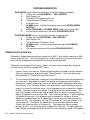
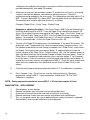
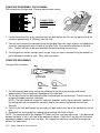
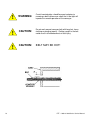
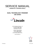
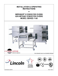
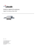
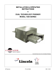
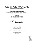
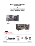
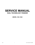
SERVICE MANUAL
(DOMESTIC & INTERNATIONAL)
DUAL TECHNOLOGY FINISHER
MODEL 1960 & 1980 SERIES
Lincoln Foodservice Products, LLC
1111 North Hadley Road
Fort Wayne, Indiana 46804
United States of America
Telephone: (260) 459-8200
U.S. Fax: (888) 790-8193
Int’l Fax: (260) 436-0735
Service Hotline: (800) 678-9511
www.lincolnfp.com
DTF1960and80serv
REV: 1/16/07
SEQUENCE OF OPERATION
DUAL TECHNOLOGY FINISHER
1961
1962
1981
1982
120/208VAC
120/240VAC
120/208VAC
120/240VAC
60 HZ.
60 HZ.
60 HZ.
60 HZ.
3 PHASE
3 PHASE
3 PHASE
3 PHASE
NOTE: DTF must be placed on an oven stand for approved operation. No other surface may be
used for operation.
POWER SUPPLY
MAIN FAN CIRCUIT
TEMPERATURE CONTROL
INFRARED HEAT
CONVEYOR DRIVE
AUTOMATIC COOL DOWN
2
Electrical power to be supplied to the oven by a five conductor service for three phase.
Black conductor is hot.
Red conductor is hot.
Orange conductor is hot.
White conductor is neutral.
Green conductor is ground.
Power is permanently supplied to the normally open main heater relays, the upper and
lower IR relays, the oven control, and, through the 10 A. motor and control fuses, to the
normally open main fan relay. Power is also supplied through a normally closed hi-limit
thermostat to terminal number 1 of the 30 minute cool down timer, and to the main
power switch. Closing the main power switch enables the 30 minute cool down timer.
The 30 minute cool down timer supplies line voltage to the coil of the main fan relay, its
contacts now close, supplying 208/240VAC to the main fan motor. Voltage is also
supplied to the primary of the control transformer, the conveyor motor, the oven control.
Closing the main power switch supplies 208/240VAC to the primary of the control
transformer. Secondary voltage, 24VAC, is supplied to the oven control. The oven
control is set to desired temperature. The thermocouple will provide varying millivolts to
the oven control. The oven control supplies voltage to the coil of the heater relays at
intermittent intervals to maintain the desired temperature. The display on the oven
control will indicate when the main heater relay is energized.
NOTE: The display also indicates oven temperature.
Adjusting the oven control will allow up to four infrared elements to be operated. The
control will energize the required relays, supplying 208/240VAC to the infrared heaters.
Closing the main power switch supplies 208/240VAC to the conveyor motor and to the
primary of the control transformer. Secondary voltage, 24VAC, is supplied to the oven
control. Setting the oven control to the desired time, outputs voltage, through a
reversing switch and capacitor, to the conveyor motor.
When the machine is started, the time delay relay timing circuit is enabled, permitting
the main fan to operate for approximately 30 minutes after the machine is shut off, to
cool the machine. The 30-minute time delay relay will keep the coil of the main fan relay
energized, maintaining operation of the main fan motor for 30 minutes.
DTF – 1960 & 1980 Series Service Manual
SCHEMATIC DIAGRAM
DOMESTIC MODELS
DTF – 1960 & 1980 Series Service Manual
3
SCHEMATIC DIAGRAM
EXPORT MODELS
4
DTF – 1960 & 1980 Series Service Manual
TROUBLESHOOTING GUIDE
1961
1962
1981
1982
SYMPTOM
Oven fan will not run
120/208 VAC
120/240 VAC
120/208 VAC
120/240 VAC
POSSIBLE CAUSE
Incoming power supply
Fuses, 10 Amp, motor and
controls
Fuse holder
Hi-limit thermostat,
Oven cavity
Switch, main power
30 minute time delay relay
Relay, main fan
Main fan motor
Capacitor
Oven will not heat
Main fan motor
Control transformer
Oven control
DTF – 1960 & 1980 Series Service Manual
60 HZ.
60 HZ.
60 HZ.
60 HZ.
3 PHASE
3 PHASE
3 PHASE
3 PHASE
EVALUATION
Check circuit breakers. Reset if required. Call power
co. if needed.
Check, replace if necessary.
Check, replace if necessary.
Terminals are normally closed. If open, reset
thermostat and retest. If thermostat will not hold for
maximum oven temperature, and oven is not exceeding
temperature setting, check for proper location of
capillary bulb in its spring holder. If the capillary checks
okay, replace the hi-limit thermostat.
Check continuity between switch terminals. Replace
switch as needed.
Check for supply voltage to 30 minute time delay relay
at terminals #1 and #6. If no voltage is present, trace
wiring back to main power switch. If there is supply
voltage at terminals #1 and #6, check for output voltage
at terminals #2 and #3. If there is incoming voltage but
no output voltage, and the main power switch is on,
replace the 30 minute time delay relay.
Check for supply voltage to relay contacts, if no voltage
is present, trace wiring back to power supply. Check for
supply voltage to the coil of the main fan relay. If no
voltage is present, trace wiring back to the 30 minute
time delay relay. If voltage is present, check to insure
contacts are closing. Replace as needed.
Check for supply voltage at motor. If no voltage is
present, trace wiring back to circuit breakers.
WITH POWER OFF: Check for opens, shorts or
grounds. Turn fan blade to check for locked rotor.
Check for shorts or grounds.
WARNING: Capacitor has a stored charge, discharge
before testing.
Check for main fan operation. If it is not operating, refer
to “Oven fan will not run”.
Check for 208/240VAC supply to the primary of the
control transformer. If no voltage is present, trace
wiring back to the main power switch. If voltage is
present, check for 24VAC at the transformer
secondary. If there is primary voltage, but no secondary
voltage, replace the control transformer.
Check for 24VAC supply to control. If no voltage is
present, trace wiring back to control transformer. If
24VAC is present, check for a read-out on the display.
If there is 24VAC supplied, but there is no read-out on
the control display, replace the oven control.
If there is a read-out on the control, set the control to
maximum temperature (see installation operations
manual for temperature adjustment). With the control
set at maximum temperature, check for supply voltage
5
Thermocouple
Oven control
Thermocouple
Oven control
Main heater relay
Heating element(s)
No Infrared Heating
Main fan motor
Infrared heater relay
Infrared Heating element(s)
6
to the oven control at terminals J3-12 and J3-3. If there
is no voltage present, trace wiring back to the air
pressure switch. If there is voltage present, check for
output voltage at the Main heater relay (R1). If there is
voltage at the Main heater relay, proceed to “Main
heater relay” for next check. If there is no voltage at the
Main heater relay, trace wiring back to the oven control.
If there is no voltage output at the oven control, check
the read-out on the control. If the control reads
“PROBE FAIL”, this indicates that the thermocouple
has failed or become disconnected from the oven
control.
Check to be sure that the thermocouple is securely
connected to the oven control. If the thermocouple is
connected to the oven control, and the control indicates
“PROBE FAIL”, disconnect the thermocouple from the
oven control and measure the resistance of the
thermocouple. The thermocouple should read approx.
11Ω. If these readings are not achieved, replace the
thermocouple. If these readings are correct, proceed.
If the thermocouple checks good, but the oven control
display indicates that there is a thermocouple failure,
replace the oven control. If the oven control indicates a
temperature reading but the oven will not heat,
proceed.
WITH POWER ON AND THERMOCOUPLE
ATTACHED TO THE OVEN CONTROL: Measure the
DC millivolt output of the thermocouple. Refer to the
thermocouple chart (located in the “Removal” section of
the manual) for proper millivolt readings. If these
readings are not achieved, replace thermocouple.
If the thermocouple checks good, but there is no
voltage output to the Main heater relay, replace the
oven control. If there is voltage output to the Main
heater relay, proceed.
Check for supply voltage to the relay coil. If voltage is
present and the relay will not activate, replace the Main
heater relay. Also check each relay contact for high
voltage input and output.
Check the Amp draw on each power leg for proper
load. Check the specification plate for rating
information. If the amp draw is high or low, check the
individual elements for opens, shorts and proper
resistance.
WITH POWER OFF: To check resistance of the
elements, remove all leads from the elements and use
a digital multimeter.
The element resistance should be as follows:
Circular element
120V – 7.5 ohms approx.
Side elements
120V – 14 ohms approx.
Replace heating elements as needed.
Check for main fan operation. If it is not operating, refer
to “Oven fan will not run”.
Check for supply voltage to the relay coil. If no voltage
is present, trace wiring back to Infrared heater switch. If
voltage is present and the relay will not activate,
replace the Infrared heater relay. Also check each relay
contact for high voltage input and output.
Check the Amp draw on each power leg for proper
DTF – 1960 & 1980 Series Service Manual
Oven heats with switch off
Main heater relay or
Infrared heater relay
Intermittent heating
Thermal/overload of motor
Conveyor will not run
NOTE: Display will indicate
“Belt Jam”
Power supply
load. Check the specification plate for rating
information. If the amp draw is high or low, check the
individual elements for opens, shorts and proper
resistance.
WITH POWER OFF: To check resistance of the
elements, remove all leads from the elements and use
a digital multimeter.
The element resistance should be as follows:
208V – 45 ohms approx.
240V – 58 ohms approx.
Replace heating elements as needed.
The Main heater relay or Infrared heater relay has
probably failed in the closed position. If there is no
voltage to the operating coil, but there is high voltage at
the relay output, replace the heater relay.
The main fan motor is equipped with internal thermal
protection and will cease to operate if overheating
occurs. As the motor overheats and then cools, this will
cause the oven to cycle on and off intermittently.
Improper ventilation or lack of preventive maintenance
may cause this. Also, most of the problems listed under
“Oven will not heat” can cause intermittent failure.
Check circuit breakers, reset if required. Check power
plug to be sure it is firmly in receptacle. Measure
incoming power, call power co. if needed.
Fuse, 10 Amp
Check, replace if necessary.
Fuse holder
Check, replace if necessary.
Hi-limit thermostat, oven cavity Terminals are normally closed. If open, reset
thermostat and retest. If thermostat will not hold for
maximum oven temperature, and oven is not exceeding
temperature setting, check for proper location of
capillary bulb in its spring holder. If the capillary checks
okay, replace the hi-limit thermostat.
Switch, Main Power
WITH POWER OFF: Check continuity between switch
terminals. Replace switch as needed.
Control transformer
Check for supply voltage to the primary of the control
transformer. If no voltage is present, trace wiring back
to the oven power relay. If voltage is present, check for
24 VAC at the transformer secondary. If there is
primary voltage but no secondary voltage, replace
control transformer.
Conveyor motor
Check for supply voltage to the conveyor motor. If no
voltage is present, trace wiring back to the primary of
the control transformer. If voltage is present and the
motor will not run, check the motor windings for opens
or shorts.
WITH POWER OFF: Check the motor windings as
follows:
Grey to black - 236 ohms approx.
Grey to brown - 236 ohms approx.
Brown to black - 472 ohms approx.
If any of the above fails, replace conveyor motor.
Capacitor, conveyor motor
Check for shorts or grounds. Replace capacitor as
needed.
WARNING: Capacitor has a stored charge, discharge
before testing.
Switch, conveyor reversing
Check continuity between switch terminals. Replace
switch as needed.
DTF – 1960 & 1980 Series Service Manual
7
Oven control
Conveyor motor runs, but there
is no speed display
Oven control
Conveyor motor
Oven control
8
If there is supply voltage to the motor, and the motor,
motor capacitor, and reversing switch check good,
replace the oven control.
Check for output voltage from oven control to hall effect
sensor (sensor is located in conveyor motor). Measure
voltage at the motor connector, red wire and yellow
wire. Voltage should be approx. 10VDC. If no voltage is
present, trace wiring back to oven control. If there is no
voltage present at the oven control, replace the oven
control.
If there is voltage supplied to the hall effect sensor,
check for a frequency output from the hall effect
sensor. Measure frequency across the yellow and white
wires at the motor connector. Frequency reading
should be approx. 25 – 100 Hz. If these readings are
not achieved, replace conveyor motor. If the readings
are achieved, proceed.
If the hall effect sensor readings are correct, but there
is no speed indicated on the display, replace the oven
control.
DTF – 1960 & 1980 Series Service Manual
REMOVAL, INSTALLATION AND ADJUSTMENT
DUAL TECHNOLOGY FINISHER
CAUTION!
BEFORE REMOVING OR INSTALLING ANY COMPONENT IN THE DUAL TECHNOLOGY
FINISHER, BE SURE TO DISCONNECT THE ELECTRICAL POWER SUPPLY.
MOTOR, MAIN FAN - REPLACEMENT
1.
2.
3.
4.
5.
6.
Shut off power at main breaker.
Remove conveyor and finger assemblies from oven (see installation operations
manual).
Remove front plenum assembly. Measure location of main fan on motor shaft for
reassembly. Loosen two set screws and remove main fan from motor shaft.
Remove rear cover. Disconnect wiring from motor. Remove motor and motor mount
assembly from back of oven.
Measure proper location of cooling fan on motor shaft for reassembly. Remove cooling
fan. Remove motor from motor mount.
Reassemble in reverse order and test for proper operation.
CAPACITOR, MAIN FAN MOTOR – REPLACEMENT
1.
2.
3.
4.
Shut off power at main breaker.
Remove rear cover, open rear access panels.
Discharge capacitor, disconnect wiring and remove capacitor.
Reassemble in reverse order and check system operation.
MAIN FAN - REPLACEMENT
See “MOTOR, MAIN FAN” above.
SWITCH, ON/OFF - REPLACEMENT
1.
2.
3.
4.
5.
Shut off power at main breaker.
Remove control box top.
Depress clips on sides of switch and remove switch from front panel.
Disconnect all wires from switch. Mark all wires for reinstallation.
Reassemble in reverse order and check system operation.
RELAY, TIME DELAY - REPLACEMENT
1.
2.
3.
4.
5.
Shut off power at main breaker.
Remove rear cover, open rear access panels.
Remove wires from time delay relay and mark wires for reinstallation.
Remove mounting screw and remove time delay relay.
Reassemble in reverse order and check system operation.
DTF – 1960 & 1980 Series Service Manual
9
RELAY, MAIN FAN - REPLACEMENT
1.
2.
3.
4.
5.
Shut off power at main breaker.
Remove rear cover, open rear access panels.
Remove wires from main fan relay and mark wires for reassembly.
Remove mounting screws and remove main fan relay.
Reassemble in reverse order and check system operation.
FUSE HOLDER - REPLACEMENT
1.
2.
3.
4.
5.
Shut off power at main breaker.
Remove rear cover, open rear access panels.
Remove wires from appropriate fuse holder and mark wires for reassembly.
Remove mounting screws from fuse holder and remove fuse holder.
Reassemble in reverse order and check system operation.
RELAY, MAIN HEATER – RELAY, INFRARED HEATER - REPLACEMENT
1.
2.
3.
4.
5.
Shut off power at main breaker.
Remove rear cover, open rear access panels.
Remove wires from appropriate relay and mark wires for reassembly.
Remove mounting screws from relay and remove relay.
Reassemble in reverse order and check system operation.
REVERSING SWITCH, CONVEYOR - REPLACEMENT
1.
2.
3.
4.
5.
Shut off power at main breaker.
Remove rear cover, open rear access panels.
Remove wires from reversing switch and mark wires for reassembly.
Remove mounting nut from reversing switch and remove reversing switch.
Reassemble in reverse order and check system operation.
TRANSFORMER, CONTROL - REPLACEMENT
1.
2.
3.
4.
5.
Shut off power at main breaker.
Remove rear cover, open rear access panels.
Remove wires from control transformer and mark wires for reassembly.
Remove mounting screws and remove control transformer.
Reassemble in reverse order and check system operation.
CAPACITOR, CONVEYOR MOTOR – REPLACEMENT
1.
2.
3.
4.
10
Shut off power at main breaker.
Remove control box top and rear control box cover.
Discharge capacitor, remove wiring from capacitor and remove one mounting screw.
Remove capacitor.
Reassemble in reverse order and check system operation.
DTF – 1960 & 1980 Series Service Manual
CONVEYOR MOTOR – REPLACEMENT
1.
2.
3.
4.
5.
6.
Shut off power at main breaker.
Remove coupling from conveyor shaft (one screw at end of motor shaft).
Remove control box top and rear control box cover.
Disconnect wiring for motor and remove motor mounting screws. Remove conveyor
motor and mounting bracket.
Remove conveyor motor from mounting bracket.
Reassemble in reverse order and check system operation.
THERMOCOUPLE – REPLACEMENT
1.
2.
3.
4.
5.
Shut off power at main breaker.
Remove control box top. Remove rear cover, open rear access panels. Remove right
side heating element cover.
Remove mounting screws and remove thermocouple from oven cavity.
Disconnect thermocouple from main control, remove thermocouple.
Reassemble in reverse order and check system operation.
THERMOCOUPLE MEASUREMENT
TEMPERATURE (°°F)
200°°
250°°
300°°
350°°
400°°
450°°
500°°
550°°
600°°
D.C. MILLIVOLTS
2.8
4.0
5.1
6.0
7.1
8.2
9.3
10.4
11.5
THERMOSTAT, HI-LIMIT – REPLACEMENT
1.
2.
3.
4.
Shut off power at main breaker.
Remove rear cover, open rear access panels, remove right side heating element cover.
Remove hi-limit thermostat mounting plate. Remove hi-limit thermostat.
Reassemble in reverse order and check system operation. Be sure to reset thermostat
before testing.
HEATING ELEMENT, MAIN – REPLACEMENT
1.
2.
3.
4.
5.
Shut off power at main breaker.
Remove conveyor, finger assemblies and plenum front. Remove rear cover, open rear
access panels and remove appropriate heating element cover.
Remove wires from heating element and mark wiring for reassembly.
Remove mounting screws and remove heating element.
Reassemble in reverse order and check system operation.
DTF – 1960 & 1980 Series Service Manual
11
HEATING ELEMENT, INFRARED – REPLACEMENT
1.
2.
3.
4.
Shut off power at main breaker.
Remove conveyor and lower finger assemblies. Remove front conveyor support from
oven cavity.
Remove front cover and heating element cover. Disconnect wiring from heating element
and mark wires for reassembly.
Reassemble in reverse order and check system operation.
MAIN CONTROL – SETTINGS
Error
Top 1
Fan
Top 2
Top 3
IR
IR
Main
Heater
Bottom
1
2
3
4
START UP
1.
2.
3.
Push the “On Off” (O / |) switch to the “ON” position. The display will indicate
“SELECT PROGRAM”
Press the #1 PROGRAM BUTTON. The toasting program will indicate “SANDWICH”
The #1 program button will blink. (Buttons #2, #3 and #4 can be used for other menu
item programs.)
Programming the unit to desired settings:
To enter the program mode, press and hold the UP BUTTON for 5 seconds.
The UP and DOWN BUTTONS will light indicating the control is in a change
status.
12
DTF – 1960 & 1980 Series Service Manual
a.
Press the TEMPERATURE BUTTON (#1) to see existing toasting
temperature. Use the UP or DOWN BUTTONS to change to desired
temperature.
Press the TIME BUTTON (#3) to see existing toasting time.
Use the UP or DOWN BUTTONS to change to desired toasting time.
b.
4.
5.
The unit will return to normal operations 10 seconds after the last button is pushed and
saves the latest program settings.
Preheat toaster for 30 minutes.
COOL DOWN CYCLE
1.
Push the “On Off” (O / |) switch to the “OFF” position. The unit’s main fan will run for
approximately 30 minutes after shutting off in a cool down mode.
PROGRAM MODE
1.
2.
To enter the PROGRAM MODE press and hold the UP BUTTON for 5 seconds. Each
button has a light that indicates when it can be used. When no buttons are pressed for
10 seconds the unit will exit the program and retain last entry.
Use the UP and DOWN BUTTONS to view or change;
a.
b.
c.
d.
TEMPERATURE SETPOINT = TEMPERATURE BUTTON (#1)
TOP IR ON/OFF = (#2) BUTTON
COOK TIME VALUE = (#3) BUTTON
BOTTOM I/Rs ON/OFF STATUS = (#4) BUTTON
The TOP I/R Icon follows the 8 available selections
The BOTTOM I/R Icon follows the 8 available selections:
Program Mode
Bottom
(0)
No Bottom IR is on
Bottom
Top 1
Top 2
Top 3
( 0 ) No top IR Heater is on
Top 3
( 1 ) Heater # 1 only
Top 3
( 2 ) Heater # 2 only
Top 3
( 3 ) Heater # 3 only
Top 3
( 4 ) Heaters # 1 & # 2 only
Top 3
( 5 ) Heaters # 1 & # 3 only
Top 3
( 6 ) Heaters # 2 & # 3 only
Top 3
( 7 ) All top IR Heaters are on
IR
(4)
Heaters #1 & #2
Top 1
Top 2
IR
Top 1
Top 2
IR
Bottom
(1)
Heater #1 only
Bottom
(5)
Heaters #1 & #3
Top 1
Top 2
IR
Top 1
Top 2
IR
Bottom
( 2 ) Heater #2 only
Bottom
(6)
Heaters #2 & #3
Top 1
Top 2
IR
Bottom
( 3 ) Heater #3 only
Bottom
(7)
All Bottom IR
Heaters on
(Factory Default)
Top 1
Top 2
IR
Top 1
Top 2
IR
DTF – 1960 & 1980 Series Service Manual
(factory default)
13
3.
Set TEMPERATURE UNITS (C° or F°).
a.
Press and hold BUTTON #1 for 20 seconds to change the C or F value.
b.
To change again, repeat step a.
4.
Set TEMPERATURE DISPLAY between REAL and SETPOINT.
a.
Press and hold BUTTON #4 for 20 seconds.
b.
To change again, repeat step a.
5.
Set LANGUAGE SELECTION.
a.
Press and hold BUTTON #2 for 20 seconds. Use UP and DOWN
BUTTONS to select language.
SUBSET POINTS MENU
1.
To enter SUBSET MENU, press and hold the TIME BUTTON (#3) for 20 seconds.
BUTTON (#3) toggles between parameter names and values.
a.
If parameter name is displayed, use the UP and DOWN arrow buttons to
browse through previous/next parameter in the list.
b.
If parameter value is displayed, use the UP and DOWN arrow buttons to
change the parameter value to within the allowed limits.
2.
Select the parameter to be adjusted by pressing the TIME BUTTON (#3) when the
parameter is displayed.
3.
Use the UP and DOWN arrow buttons to change the value within the allowed limits.
(See Chart below).
4.
To EXIT the menu, press TIME BUTTON (#3) for 3 seconds. Or, if no button is pressed
for 30 seconds, the unit will automatically EXIT the SUBSET MENU.
SUBSET LIMITS / DEFAULTS
PARAMETER
DEFAULT SET POINT
(Preheat Mode)
Main Heater
PROBE OFFSET
Main Heater
MAXIMUM SET POINT
Main Heater
MINIMUM SET POINT
DEFAULT COOK TIME
CALIBRATION
(Conveyor Speed)
VALUE LIMITS
F: 32° to 700°
C: 0° to 370°
F: -200° to 200°
C: -129° to 94°
F: 32° to 700°
C: 0° to 370°
F: 32° to 700°
C: 0° to 370°
0:14 to 10:00 (MM:SS)
-4 to 4
See instructions below
FACTORY DEFAULT
F: 575°
C: 300°
F: -60°
C: -33°
F: 650°
C: 340°
F: 215°
C: 100°
0:21 (MM:SS)
0
NOTE
CALIBRATION instructions: The calibration must be done at 33 seconds of cook time. A
positive value in this parameter accelerates the conveyor and a negative value decelerates the
conveyor.
14
DTF – 1960 & 1980 Series Service Manual
SYSTEM DIAGNOSTICS
SAFE MODE: Occurs when the unit detects a defective temperature probe.
a.
Display will scroll SAFE MODE – CALL SERVICE.
b.
Main Heater is off.
c.
Selected COOK program light is on.
d.
Top and Bottom I/R heaters are on.
e.
Error light is on.
f.
ALARM sounds. (Can be turned off by pressing the DOWN ARROW
BUTTON.)
g.
COOK PROGRAM and SUBSET MENU modes are not accessible.
h.
Unit can be restarted after a 30 minute COOLDOWN CYCLE.
SHUTDOWN MODE: Occurs when the unit detects a conveyor error.
a.
Display will scroll SHUTDOWN - CALL SERVICE.
b.
Main Heater is off.
c.
Top and Bottom I/R Heaters are off.
d.
ALARM sounds. (Can be turned off by pressing the UP ARROW
BUTTON.)
e.
Unit can be restarted after 30 minute COOLDOWN CYCLE.
TEMPERATURE CALIBRATION
Calibration is to be performed with oven control set at 650° F, with the belt speed set at 4:00
minutes and all IR’s off. The cavity temperature is to be measured in the center of the oven
cavity with the temperature-sensing device resting on the conveyor belt.
Calibration must be done with all covers, fingers, air washes and conveyor belt in place to
ensure accuracy for Gecko-equipped DTT ovens.
1.
If oven is not on, turn oven on. Display will light up and run through start-up sequence.
After start-up sequence, display will scroll “Select Program”. Press and release the
button labeled “3”. Display will scroll “Menu Item 3”.
2.
To set the oven for calibration, simply press and hold the button with the arrow pointing
up (“up arrow”). After about 5 seconds, the display will change to read the correct
temperature set point and the light next to the button number will become solid rather
than flashing. If the “up arrow” button is not released the set point will begin to go up
unless it is already at maximum value. Use the up/down arrows to adjust this set point
to “650”. Next press and release button ”3” to bring up the belt speed set point. The
light on this button should now be solid to indicate that this option is currently active.
Adjust the up/down arrows to read “4:00”. Press and release button “2” and the light by
this button will come on. Use up/down arrows to change this setting to “0 (zero)”.
Above the numbered button are 5 labeled lights, the two on the far right indicate the
state of the IRs. The light above the “Top IR” should be off. Last, press button “4” to
set the lower IRs. The light on the bottom will turn on and lights above the label
“Bottom” will show the status of the lower IRs. The display will show a number
between 0 and 7. Use the arrow button to adjust this value to 0. The lights above the
label “Bottom” will change to indicate which IRs are on and which are off. After properly
DTF – 1960 & 1980 Series Service Manual
15
setting oven for calibration, do not press any buttons and the control will return to heat
up mode automatically after about 10 seconds.
3.
Allow oven to heat up. Light on button number “3” should flash until oven is up to temp
set point, then light will become solid and oven will begin to cycle. Check the
temperature being recorded in the oven cavity. This temperature should be within 5°F of
650° . If temp is below 645°F or above 655°F then the probe offset must be adjusted.
The equation to be used for adjusting the offset is as follows:
Change in Probe Offset = Cavity Temp – Display Temp
Examples of adjusting the offset: If the Cavity Temp is 550°F and the Probe offset is
0 with the display temp set at 575°F, then the Probe Offset should be set around –25
(minus 25) to make the cavity temp equal to the Display Temp. If the Cavity Temp is at
565°F with the Display Temp set at 575°F, then the Probe Offset must change by –10
degrees. For example, if the Probe Offset was at –40 and the change in the Probe
Offset is calculated to be –15 then the Probe Offset must be –55.
4.
To access the Probe Offset option, press the hold button “3” for about 30 seconds. The
display will scroll “Temperature Units” when the control enters the correct menu. Use
the up/down arrow button to scroll through the options until “Probe Offset” scrolls across
the display. At this point, press and release button “3” and the display will show the
current set point of the Probe Offset. Default setting is –60. Use the up/down arrows to
adjust the offset based on the calculated Change in Probe Offset from above. Once the
Probe Offset is changed to the desired value, press and hold button “3” for 3 seconds
to exit the menu. Oven will now return to the heat mode and the light next to button “3”
should flash until oven reaches set temperature of 600°F. Check the cavity temperature
again after oven temperature has stabilized to ensure that the Probe Offset is now
correct.
5.
Once the cavity temp and display temp match within 5° F, the calibration is complete.
6.
Press Program 1 key. IRs will turn on, and the settings are preset. Maximum
temperature setting is 650°F. Cavity temperature should reach 710°F to 760°F.
Calibration is complete.
NOTE: Cavity temperature should not exceed 825°F. If Hi Limit trips replace Hi-Limit.
MAIN CONTROL – REPLACEMENT
1.
2.
3.
4.
5.
16
Shut off power at main breaker.
Remove control box top, front panel and rear control box cover.
Disconnect all wiring from control and mark all wiring for reassembly.
Remove mounting screws from main control and remove main control board.
This is a two piece control, be sure to replace both parts when the control is replaced.
Reassemble in reverse order and check system operation.
DTF – 1960 & 1980 Series Service Manual
CONVEYOR DISASSEMBLY FOR CLEANING
Pull conveyor out the right end. Place on table or work surface.
CONNECTING
LINKS IN THREE
PLACES
1. Locate connecting links on the conveyor belt, turn belt to place the links on the top left end of the
conveyor approximately 8” (203mm) from the shaft.
2. You can easily remove the connecting links by grasping them with a pair of pliers and slipping the
eye of the connecting link over the wire of the other links. Also notice the direction of the other
links. The belt will have to be reinstalled with the opening facing the same way.
3. Carefully pull out the belt, rolling it up as you go. After you have it removed it may be placed in a
pan of detergent solution to soak. Rinse with clean water.
CONVEYOR REASSEMBLY
Conveyor Belt Installation
1. Put conveyor belt back on by setting the rolled belt to the left of the conveyor and thread
approximately 2/3 of the belt over the bottom of the slider bed.
2. Put the loose end of the belt around the idler shaft and back on the conveyor. The belt must lay
on top of the upper conveyor slider bed.
NOTE: The belt should curl around the conveyor sprockets and lay flat on top of the sprockets. If
the belting does not curl around the sprockets and lay flat, remove the belting and turn over.
Reinstall.
3. Pull all of the slack belt through the conveyor until both ends are on top of the conveyor on the left
end.
4. Reconnect the conveyor belt by slipping the connecting links back in place.
NOTE: The conveyor belt of the Impinger DTF does not have a tension adjustment. If the belt would
become too loose, a link(s) will have to be removed to tighten. A belt that is too tight will also cause
operational problems due to excessive drag. We suggest that you have a qualified service person
perform this adjustment.
DTF – 1960 & 1980 Series Service Manual
17
18
!
WARNING:
Careful consideration should be exercised prior to
removing a belt link because a belt that is too tight will
impede the smooth operation of the conveyor.
!
CAUTION:
Do not work around conveyor belt with long hair, loose
clothing or dangling jewelry. Getting caught in the belt
could result in dismemberment or fatal injury.
!
CAUTION:
BELT MAY BE HOT!
DTF – 1960 & 1980 Series Service Manual
This page intentionally left blank.
DTF – 1960 & 1980 Series Service Manual
19
GENERAL VIEW
MODEL 1960 SERIES
A
B
C
D
E
F
G
H
I
J
K
L
M
N
O
P
R
S
T
U
V
W
X
Y
20
370515
370593
370594
370587
370578
370595
370450
370596
370596
370581
370579
370585
370619
370597
370598
370587
370579
370580
370596
370596
370595
370578
370585
369373
Rubber Bumper
Front Cover
Front Element Cover
Finger Housing, Bottom Right – Marked “B2”
Columnating Panel, Bottom Right & Left
Finger Cover, Bottom Right & Left
¼ Turn Fastener
Air Wash Assembly
Air Wash Assembly
Finger Cover, Top Right
Columnating Panel, Top Right
Finger Housing, Top Right – Marked “T2”
Plenum Front
Drive Shaft Cover
Top Cover
Finger Housing, Top Left – Marked “T1”
Columnating Panel, Top Left
Finger Cover, Top Left
Air Wash Assembly
Air Wash Assembly
Finger Cover, Bottom Left
Columnating Panel, Bottom Left
Finger Housing, Bottom Left – Marked “B1”
Receptacle, Snap-In
DTF – 1960 & 1980 Series Service Manual
GENERAL VIEW
MODEL 1960 SERIES
DTF – 1960 & 1980 Series Service Manual
21
CONTROL BOX
MODEL 1960 SERIES
A
B
C
D
E
F
G
H
I
J
K
Not Shown
L
M
N
O
P
22
369432
370573
370599
370571
370383
370519
370600
370462
370601
370547
See Page 26
See Page 26
350259
370106
369413
369460
369410
Switch, on/off
Label, control panel
Front panel
Control, main and display
Capacitor, conveyor motor
Bracket, Motor
Cover, rear control box
Motor, conveyor
Top, control box
Gasket, Conveyor Motor
Heating element, Infrared (s/n 8001208 & below)
Heating element, Infrared (s/n 8001209 & above)
Screw
Washer
Drive key
Spring, compression
Coupling sleeve
DTF – 1960 & 1980 Series Service Manual
CONTROL BOX VIEW
MODEL 1960 SERIES
DTF – 1960 & 1980 Series Service Manual
23
REAR VIEW
MODEL 1960 SERIES
A
B
C
D
E
F
G
H
I
J
K
L
M
N
O
P
Q
R
S
T
U
V
W
Y
Z
AA
BB
CC
DD
EE
24
370475
370603
370618
370604
370603
370546
370342
370570
369422
370538
370515
370569
370582
370583
370693
370694
370552
369166
369129
357067
369192
370576
370577
See Page 27
369427
370466
369422
370606
369033
370607
370605
Cover, Rear
Cover, Heating Element
Motor Mount
Electrical Panel, RH
Cover, Heating Element
Fuse, 8A
Fuse Holder
Relay, Impingement Heating Elements
Relay, Main Fan
Relay, IR Elements
Rubber Bumper
Relay, Solid State
Contactor, 3 Pole
Power Cord
Strain Relief (domestic models only)
Strain Relief (export models only)
Reversing Switch, Conveyor
Fuse, 10A
Fuse Holder
Thermostat, Hi-Limit
Capacitor
Thermocouple
Main Fan
Heating Element Chart
Transformer, Control
Timer, Cool Down, 30 minute
Relay, Main Fan
Cooling Fan
Hose Clamp
Motor, Main Fan
Electrical Panel, LH
DTF – 1960 & 1980 Series Service Manual
REAR VIEW
MODEL 1960 SERIES
DTF – 1960 & 1980 Series Service Manual
25
I.R. ELEMENTS VIEW
MODEL 1960 SERIES
S/N 8001209 AND ABOVE
Model Description
1961
1962
1962-000-E
1963-000-E
1964-000-E
1964
Part Number
370695
370696
370696
370698
370697
370697
S/N 8001208 AND BELOW
Model Description
1961
1962
26
Part Number
370602
370616
DTF – 1960 & 1980 Series Service Manual
MAIN FAN ELEMENTS VIEW
MODEL 1960 SERIES
S/N 8001209 AND ABOVE
Model Description
1961
1962
1962-000-E
1963-000-E
1964-000-E
1964
Part Number
370699
370702
370702
370700
370701
370701
S/N 8001208 AND BELOW
A
B
Model Description
A – 120 VAC (1961)
A – 240 VAC (1962)
B – 120 VAC Circular (1961)
B – 240 VAC Circular (1962)
DTF – 1960 & 1980 Series Service Manual
Part Number
370630
370461
370629
370617
27
CONVEYOR
MODEL 1960 SERIES
A
B
C
D
E
F
G
H
I
J
K
L
M
not shown
not shown
not shown
370610
370509
369516
370611
369471
10000550
369412
370608
369920
370622
370609
369922
370613
370615
370614
370612
Shaft, idler
Drive Sprocket
Bearing, Conveyor
Shaft, Drive
Pin
Frame, Conveyor
Connecting Link, Conveyor (three required)
Belt, Conveyor
Stud Retainer, Tinnerman
Roller, Conveyor Belt
Bracket, Conveyor Bearing
Support Rod, Bottom
Bearing, High Temp
Crumb Pan, Drive End
Crumb Pan, Idle End
Conveyor Assembly, Complete
CONVEYOR VIEW
MODEL 1960 SERIES
28
DTF – 1960 & 1980 Series Service Manual
This page intentionally left blank.
DTF – 1960 & 1980 Series Service Manual
29
GENERAL
MODEL 1980 SERIES
A
B
C
D
E
F
G
H
I
J
K
L
M
N
O
P
R
S
T
U
V
W
X
Y
30
370515
370593
370594
7008848-1
7008844
370703
370450
9005450
9005450
370703
7008844
7008848-2
370619
370597
370598
7008848-1
7008844
370703
9005450
9005450
370703
7008844
7008848-2
369373
Rubber Bumper
Front Cover
Front Element Cover
Finger Housing, Bottom Right
Columnating Panel
Finger Cover
¼ Turn Fastener
Air Wash Assembly
Air Wash Assembly
Finger Cover
Columnating Panel
Finger Housing, Top Right
Plenum Front
Drive Shaft Cover
Top Cover
Finger Housing, Top Left
Columnating Panel
Finger Cover
Air Wash Assembly
Air Wash Assembly
Finger Cover
Columnating Panel
Finger Housing, Bottom Left
Receptacle, Snap-In
DTF – 1960 & 1980 Series Service Manual
GENERAL VIEW
MODEL 1980 SERIES
DTF – 1960 & 1980 Series Service Manual
31
CONTROL BOX
MODEL 1980 SERIES
A
B
C
D
E
F
G
H
I
J
K
Not Shown
L
M
N
O
P
32
369432
370573
370599
370571
370383
370519
370600
370462
370601
370547
See Page 36
See Page 36
350259
370106
369413
369460
369410
Switch, on/off
Label, control panel
Front panel
Control, main and display
Capacitor, conveyor motor
Bracket, Motor
Cover, rear control box
Motor, conveyor
Top, control box
Gasket, Conveyor Motor
Heating element, Infrared (s/n 8001208 & below)
Heating element, Infrared (s/n 8001209 & above)
Screw
Washer
Drive key
Spring, compression
Coupling sleeve
DTF – 1960 & 1980 Series Service Manual
CONTROL BOX VIEW
MODEL 1980 SERIES
DTF – 1960 & 1980 Series Service Manual
33
REAR VIEW
MODEL 1980 SERIES
A
B
C
D
E
F
G
H
Not Shown
I
K
L
M
N
O
P
Q
R
S
T
U
V
Not Shown
Not Shown
Y
Z
AA
BB
CC
DD
EE
34
370704
370603
370618
370604
370603
370546
370342
370551
370570
369422
370515
370569
370582
370583
370693
370694
370552
369166
369129
357067
369192
370576
370577
See Page 37
See Page 37
369427
370466
369422
370606
369033
370607
370605
Cover, Rear
Cover, Heating Element
Motor Mount
Electrical Panel, RH
Cover, Heating Element
Fuse, 8A
Fuse Holder
IR Element Relay Assembly
IR Element Relay (Relay Only)
Relay, Main Fan
Rubber Bumper
Relay, Solid State
Contactor, 3 Pole
Power Cord
Strain Relief (domestic models only)
Strain Relief (export models only)
Reversing Switch, Conveyor
Fuse, 10A
Fuse Holder
Thermostat, Hi-Limit
Capacitor
Thermocouple
Main Fan
Main Fan Element (s/n 8001208 & below)
Main Fan Element (s/n 8001209 & above)
Transformer, Control
Timer, Cool Down, 30 minute
Relay, Main Fan
Cooling Fan
Hose Clamp
Motor, Main Fan
Electrical Panel, LH
DTF – 1960 & 1980 Series Service Manual
REAR VIEW
MODEL 1980 SERIES
DTF – 1960 & 1980 Series Service Manual
35
I.R. ELEMENTS VIEW
MODEL 1980 SERIES
S/N 8001209 AND ABOVE
Model Description
1981
1982
1982-000-E
1983-000-E
1984-000-E
1984
Part Number
370458
370460
370460
370535
370534
370534
S/N 8001208 AND BELOW
Model Description
1981
1982
36
Part Number
370602
370616
DTF – 1960 & 1980 Series Service Manual
MAIN FAN ELEMENTS VIEW
MODEL 1980 SERIES
S/N 8001209 AND ABOVE
Model Description
1981
1982
1982-000-E
1983-000-E
1984-000-E
1984
Part Number
370705
370708
370708
370706
370707
370707
S/N 8001208 AND BELOW
Model Description
1981
1982
DTF – 1960 & 1980 Series Service Manual
Part Number
4040283
4040283
37
CONVEYOR
MODEL 1980 SERIES
A
B
C
D
E
F
G
H
I
J
K
L
M
N
O
Not shown
370477
370478
370480
370526
370481
370529
370650
370509
370479
369952
10000551-3
10000551-2
370482
369471
370483
10000830
Crumb pan, drive end
Crumb pan, idle end
Bracket, conveyor bearing
Bushing, bearing retainer
Flanged bearing, conveyor
Conveyor frame
Sprocket, idle
Drive sprocket
Conveyor belting
Connecting links (three required)
Pan stop, drive end
Pan stop, idle end
Shaft, idler
Pin
Shaft, drive
Conveyor assembly, complete
CONVEYOR VIEW
MODEL 1980 SERIES
38
DTF – 1960 & 1980 Series Service Manual
This page intentionally left blank.
DTF – 1960 & 1980 Series Service Manual
39
Lincoln Foodservice Products, LLC
1111 North Hadley Road
Fort Wayne, Indiana 46804
United States of America
Telephone: (260) 459-8200
U.S. Fax: (888) 790-8193
Int’l Fax: (260) 436-0735
Service Hotline: (800) 678-9511
www.lincolnfp.com
40
DTF – 1960 & 1980 Series Service Manual