1
INSTALLATION & OPERATING
INSTRUCTIONS
for
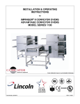
DUAL TECHNOLOGY FINISHER
MODEL 1960 & 1980 SERIES
1980 Series
1960 Series
TO BE SERVICED ONLY BY AUTHORIZED PERSONS
DTF1960and80ops
P/N: 2810322
REV: 2/19/07 - E
TABLE OF CONTENTS
SAFETY INFORMATION...................................................................................…..............3
PURCHASER’S RESPONSIBILITY.................................................................................... 4
MODEL NUMBER KEY...…………….................................................................................. 4
EXTERIOR DIMENSIONS...................................................................................................5
COMPONENTS................................................................................................................... 5
ELECTRICAL GROUNDING INSTRUCTIONS..................................................…............. 6
REQUIRED CLEARANCE / SPACING / PLACEMENT..................................................... 6
VENTILATION..................................................................................................................... 6
GENERAL INFORMATION................................................................................................. 6
UNCRATING....................................................................................................................... 6
INFORMATION OF USE..................................................................................................... 7
HOW TO OBTAIN SERVICE.............................................................................................. 7
OPERATOR MAINTENANCE............................................................................................. 7
PREVENTIVE MAINTENANCE......................................................................................... 7
DISASSEMBLY & ASSEMBLY INSTRUCTIONS...................................................…........8
CONVEYOR REMOVAL & REINSTALLATION................................................................. 8
CLEANING INSTRUCTIONS.............................................................................................. 11
FINGER ASSEMBLY.......................................................................................................... 13
START UP / SHUT DOWN / PROGRAM MODE................................................................ 15
DISASSEMBLY & ASSEMBLY “QUICK REFERENCE GUIDE”...........................…........ 17
LABEL DEFINITIONS...........................................…………………..................................... 18
FUNCTIONS – REVERSING & THERMAL CUT-OUT SWITCHES………………….…….. 19
CONCEPTS......................................................................................................................... 20
ADDENDUM A – STACKING BRACKETS........................................................................ 21
WARRANTY........................................................................................................................ 22
UTILITY SPECIFICATION
2
Model #
1981
1982
1982-000-E
1983-000-E
1984-000-E
1984
Model Description
DTF-8 208/3 1000W
DTF-8 240/3 1000W
DTF-8 415/240/3 1000W
DTF-8 400/230/3 1000W
DTF-8 380/220/3 1000W
DTF-8 220/3 1000W
Voltage
208
240
415/240
400/230
380/220
220
KW
11.3
11.3
11.3
11.3
11.3
11.3
Amps
36
31.5
31.5
32.8
34.2
34.2
Phase
3
3
3
3
3
3
HZ
60
60
50
50
50
60
1961
1962
1962-000-E
1963-000-E
1964-000-E
1964
DTF-16 208/3 1100W
DTF-16 240/3 1100W
DTF-16 415/240/3 1100W
DTF-16 400/230/3 1100W
DTF-16 380/220/3 1100W
DTF-16 220/3 1100W
208
240
415/240
400/230
380/220
220
11.5
11.5
11.5
11.5
11.5
11.5
39.5
34.5
34.5
36
37.5
37.5
3
3
3
3
3
3
60
60
50
50
50
60
DTF – 1960 & 1980 Series Operations Manual
WARNING AND SAFETY INFORMATION
IMPORTANT
FOR YOUR SAFETY, DO NOT STORE OR USE GASOLINE OR OTHER FLAMMABLE
VAPORS OR LIQUIDS IN THE VICINITY OF THIS OR ANY OTHER APPLIANCE.
DO NOT SPRAY AEROSOLS IN THE VICINITY OF THIS APPLIANCE WHILE IT IS IN
OPERATION.
WARNING: IMPROPER INSTALLATION, ADJUSTMENT, ALTERATION, SERVICE OR
MAINTENANCE CAN CAUSE PROPERTY DAMAGE, INJURY OR DEATH. READ THE
INSTALLATION, OPERATING, AND MAINTENANCE INSTRUCTIONS THROUGHLY
BEFORE INSTALLING OR SERVICING THIS EQUIPMENT.
•
•
•
•
Minimum clearances must be maintained from all walls and combustible materials (page 6).
•
•
•
•
The Finisher is to be operated only on the type of electricity as shown on the specification plate.
Keep the finisher area free and clear of combustible material.
Adequate clearance for air openings to the control chamber is required.
Do not obstruct the ventilation holes in the control box and front of the Finisher as these provide cooling air
for the controls.
This manual should be retained for future reference.
The electrical wiring diagram is located under the control box cover.
The fixed supply wiring insulation must be protected against high interior surface temperatures.
DTF – 1960 & 1980 Series Operations Manual
3
PURCHASER’S RESPONSIBILITY
It is the responsibility of the purchaser:
1. To see that the electric services for the Finisher are installed on site in accordance with the manufacturers
specification.
2. To unload, uncrate, and install the Finisher in its proper location; in accordance with this installation
operation manual.
3. To ensure that Finisher is placed on an oven stand for operation. Any surface other than an oven stand is
unacceptable.
4. To see that the electrical services are connected properly by a qualified installer of your choice. All such
connections must be in accordance with applicable code requirements. Refer to page 5 for specific code
references.
5. The fixed supply wiring insulation must be protected against high interior surface temperatures.
NOTE: Do not install the unit(s) in any area with an ambient temperature in excess of 95°F /
35°C. Doing so will cause damage to the unit(s).
MODEL NUMBER KEY
COUNTRY
France
Germany
Italy
Spain
United Kingdom
Luxembourg
Portugal
Denmark
Belgium
Netherlands
Ireland
Greece
Austria
Finland
Norway
Sweden
LANGUAGE
French
German
Italian
Spanish
English
French
Portuguese
Danish
Dutch / French
Dutch
English
Greek
German
Finnish
Norwegian
Swedish
CODE
B
C
D
E
F
B
H
J
K
L
F
M
C
N
P
R
EXAMPLE: 1963-B00-EA
1963-
B
00-
E
E = EC Marked Units
00 = Special Unit Designation
(02 = All Stainless Unit)
B = Language
1963 = Main Model Number
4
DTF – 1960 & 1980 Series Operations Manual
EXTERIOR DIMENSIONS
DUAL TECHNOLOGY FINISHER
UNIT MODEL
A
B
Model 1960
35” / 889 mm
17” / 432 mm
Model 1980
25” / 635 mm
9½” / 241 mm
COMPONENTS
REQUIRED CLEARANCE
The unit must have 6 inches (152 mm) of
clearance from combustible surfaces. In case
4” LEG
other equipment is located on the right side of
the unit, a minimum clearance of 24 inches
(610 mm) is required from that equipment.
ANGLE PLUG – 50 AMP, 250 VAC, 3 PHASE
(Domestic units only)
(Wire & Plug not included with CE units)
FOR ALL UNITS: A 24-inch (610-mm)
clearance at the rear of the unit must be
obtainable for service access.
DTF – 1960 & 1980 Series Operations Manual
5
ELECTRICAL GROUNDING INSTRUCTIONS
Model 1900 Series
!
WARNING
This appliance must be properly grounded at time of installation.
Failure to ensure that this equipment is properly grounded can result
in electrocution, dismemberment or fatal injury.
ELECTRICAL CODE REFERENCE
IN USA
When installed, this appliance must be electrically grounded and its installation must comply with the
National Electric Code, ANSI-NFPA 70, latest version, the Manufacturer’s Installation Instructions, and
applicable municipal building codes.
IN CANADA
All electrical connections are to be made in accordance with CSA C22.1, latest version, Canadian Electrical
Code Part 1 and/or Local Codes.
ALL OTHER COUNTRIES
Local electrical codes will prevail.
1. Strain Relief is provided with each oven. International Dealer/Distributors provide applicable power
cord/plug for each customer.
2. All pole disconnection switch 3mm open contact distance.
3. To prevent electrical shock, an equal potential bonding ground lug is provided in the back. This allows
the oven to be connected to an external bonding system.
4. If used as a double-stack and each Finisher has its own disconnection switch, all switches should be
close together.
REQUIRED CLEARANCES / SPACING / PLACEMENT
The unit must have 6 inches (152 mm) of clearance from combustible surfaces. In case other equipment is
located on the right side of the unit, a minimum clearance of 24 inches (610 mm) is required from that
equipment.
FOR ALL UNITS: A 24-inch (610-mm) clearance at the rear of the unit must be obtainable for service access.
Dual Technology Finisher must be placed on an oven stand for proper operation. No other surfaces may be
used for operation of this unit.
VENTILATION
Local codes prevail. These are the “authority having jurisdiction” as stated by the NATIONAL FIRE
PROTECTION ASSOCIATION, INC. in NFPA 96-1994.
GENERAL INFORMATION
The instructions that follow are intended as a guide for preparing for the installation of the Lincoln Dual
Technology Finisher unit.
First and foremost, each crate should be examined before signing the Bill of Lading to report any visible damage
caused by shipment, and account for the number of crates.
IF THERE IS APPARENT DAMAGE: United States and Canada – arrangements should be made to file a claim
against the carrier. As Interstate Commerce Regulations require that the claim must be initiated by the
consignee. All shipments to other countries – Freight terms will be developed and extended on an individual
basis.
Proper and secure storage facilities should be arranged for the unit(s), if necessary, to protect against outdoor
or damp conditions at all times before installation.
~ DO NOT LIFT EXCESSIVE WEIGHT ~
UNCRATING
When you have all the crates unloaded, open the crates and remove any protective packaging. Inspect at once
for concealed damage. If anything appears to be damaged, contact the appropriate persons immediately to file a
damage claim. After completing this inspection, finish unpacking the unit(s) and all other components.
6
DTF – 1960 & 1980 Series Operations Manual
INFORMATION ON USE OF UNIT
WARNING
DANGER :
!
DO NOT USE PARCHMENT PAPER WHEN PLACING FOOD PRODUCT THROUGH THE OVEN
WITH THE INFRA-RED (IR) HEATING ELEMENTS ON! USE OF SUCH MATERIALS WITH THE
HEATING ELEMENTS ON MAY CAUSE A FIRE AND SHOULD NEVER BE PLACED IN THE OVEN.
PARCHMENT PAPER MAY ONLY BE USED WHEN ALL HEATING ELEMENTS ARE OFF AND THE
OVEN IS IN “IMPINGEMENT MODE” ONLY. SEE PAGE 16 FOR PROGRAMMING INSTRUCTIONS.
As explained in “Concepts” (page 20), the Lincoln Impinger DTF functions by directing high velocity streams of
heated air directly on the food products. Because air and infrared are the heat sources, it is effective even on
sensitive foods. Compared to conventional ovens and even convection ovens, the cooking time of products in
the DTF can be two (2) to four (4) times faster. Several factors may affect the cooking time of any special
products such as:
1. Unit temperature setting.
2. Conveyor speed.
HOW TO OBTAIN SERVICE
If the unit fails to operate, check the circuit breaker to be sure it is turned on. Also check the fuses and resets on
the back side panel to be sure that they are good before you call the Authorized Service Agency. The name and
phone number of the Authorized Service Agency should be located on the oven, or contact the factory at 1-800678-9511 for the name of the nearest Authorized Service Agency.
OPERATOR MAINTENANCE
!
!
WARNING
DANGER :
DISCONNECT POWER SUPPLY BEFORE SERVICING OR CLEANING THIS OVEN.
SAFEGUARD AGAINST POWER SO IT CANNOT BE ACCIDENTALLY RESTORED.
FAILURE TO DO SO COULD RESULT IN DISMEMBERMENT, ELECTROCUTION OR
FATAL INJURY.
WARNING:
IF THE SUPPLY CORD APPEARS TO BE DAMAGED, DO NOT ATTEMPT TO
OPERATE UNIT. CONTACT A SERVICE AGENT OR QUALIFIED ELECTRICIAN TO
REPAIR.
Extensive engineering went into this unit to make it as maintenance free as possible. There is no lubrication
required.
However, to achieve the maximum efficiency of the unit, it is necessary to keep it clean. For cleaning
instructions see page 11. The frequency listed is only the factory’s recommendations. Your use and type of
products will actually determine the frequency of cleaning.
If the unit fails to operate, check the circuit breaker to be sure it is turned on. Also check the fuses and resets on
the back, side panel to be sure that they are good before you call the Authorized Service Agency. The name
and phone number of the Authorized Service Agency should be located on the oven, or contact the factory at 1800-678-9511 for the name of the nearest Authorized Service Agency.
PREVENTIVE MAINTENANCE
Although this unit has been designed to be as trouble free as possible, periodic Preventive Maintenance is
essential to maintain peak performance. It is necessary to keep motors, fans, and electronics free of dirt, dust
and debris to insure proper cooling. Overheating is detrimental to the life of all components mentioned.
The periodic intervals of preventive cleaning may vary greatly depending on the environment in which the unit is
operating.
You must discuss this need for Preventive Maintenance with your Authorized Service Company to establish a
proper program.
If there are any questions that the Service Company cannot answer, contact Lincoln’s Technical Service
Department at 1-800-678-9511.
DTF – 1960 & 1980 Series Operations Manual
7
DISASSEMBLY & ASSEMBLY INSTRUCTIONS
OTHER THAN OPTIONAL LEGS, THIS UNIT WHEN RECEIVED IS READY FOR OPERATION AFTER
BEING PLUGGED INTO AN ELECTRICAL SOURCE.
FOR INFORMATION ON STACKING TWO DTF OVENS TOGETHER, SEE “ADDENDUM A” FOR
INSTRUCTIONS.
!
CAUTION:
UNIT MUST BE COOL BEFORE PROCEEDING WITH
DISASSEMBLY. SWITCH UNIT OFF AND WAIT 30 MINUTES
FOR COOL-DOWN. DISCONNECT FROM POWER SUPPLY.
Conveyor Assembly
Crumb Pans
1. Remove left and right crumb pans by lifting the outside edge upwards and then sliding off.
2. Remove conveyor by pushing in the conveyor coupling (1). While holding coupling in, lift up on conveyor (2)
and slide out of unit. Install in reverse order.
Conveyor Coupling
1
2
8
DTF – 1960 & 1980 Series Operations Manual
3. Remove the Top and Bottom Air Wash Assemblies. Please note that the Top and Bottom Air Wash
Assemblies are interchangeable and, therefore, can be removed and reinstalled in any of the four locations.
Each of these is attached by two 1/4-turn fasteners.
¼-Turn Fasteners
Top and Bottom Air Wash Assemblies
(NOTE: Similar Assemblies are also
found on back of unit.)
DTF – 1960 & 1980 Series Operations Manual
9
4. Remove bottom finger assemblies by sliding out of each side. These are marked “B1” (bottom left) and “B2”
(bottom right).
5. Remove the top finger assemblies by sliding out each side. These are marked “T1” (top left) and “T2” (top
right).
6. Reassemble in reverse order.
10
DTF – 1960 & 1980 Series Operations Manual
CLEANING INSTRUCTIONS
The Lincoln Impinger Dual Technology Finisher contains electrical components. Before cleaning the unit,
switch off and allow unit to cool for 30 minutes then disconnect from the electrical supply.
No electrical components should be subjected to moisture. It is therefore important that the oven is wiped down
carefully. NEVER throw buckets of water over the oven or subject it to pressure washing from a hose of
pressure spray. If water or other liquid is spilled on the unit, make sure that none has entered the control box
area before switching on. If in doubt, call your service company.
DAILY CLEANING REQUIREMENTS
!
CAUTION:
SWITCH UNIT OFF AND WAIT 30 MINUTES FOR COOL-DOWN
BEFORE PROCEEDING WITH CLEANING. UNIT MUST BE
COOL. DO NOT USE POWER CLEANING EQUIPMENT, STEEL
WOOL, OR WIRE BRUSHES ON STAINLESS STEEL
SURFACES.
1. Clean exterior surfaces of the unit by wiping it down with a mild detergent and clean water, or a commercial
stainless steel cleaner.
2. Clean the conveyor belt by wiping with a cleaning cloth or brushing with a soft wire brush.
NOTE: DO NOT use a caustic or an alkaline base cleaner on the interior of the unit. This will ruin the finish of
the interior. On the exterior of the unit, removal of deposits of baked-on splatter, oil, grease, or light
discolorations may be removed with any of several commercial cleaners. Consult with your local supplier.
WEEKLY CLEANING REQUIREMENTS
!
CAUTION:
SWITCH UNIT OFF AND WAIT 30 MINUTES FOR COOL-DOWN
BEFORE PROCEEDING WITH CLEANING. UNIT MUST BE
COOL. DO NOT USE POWER CLEANING EQUIPMENT, STEEL
WOOL, OR WIRE BRUSHES ON STAINLESS STEEL
SURFACES.
1. Remove conveyor by pushing in the conveyor coupling (1). While holding coupling in, lift up on conveyor (2)
and slide out of unit. Place conveyor in large sink for cleaning. Spray entire conveyor with commercial oven
cleaner. Let sit for 15-20 minutes, use 3M green scrub pad to remove debris. Rinse and let dry.
Conveyor Coupling
1
2
DTF – 1960 & 1980 Series Operations Manual
11
2. Remove Air Wash Assemblies by releasing the ¼ turn fasteners. Please note that the Upper and Lower Air
Wash Assemblies are interchangeable and, therefore, can be removed and reinstalled in any of the four
locations. Clean each Air Wash Assembly with commercial oven cleaner and rinse. Allow time to dry
before reinstallation.
¼-Turn Fasteners
3. Remove Finger Assemblies by sliding out either end of unit. Slide the Finger Cover from Finger Housing,
remover Inner Columnating Panel and clean all pieces with commercial oven cleaner and rinse (see pages
13-14 for additional information and detailed drawings). Allow time to dry before reinstallation. Upon
reinstallation, please note that proper placement of finger assemblies is critical to unit operation. Top Finger
“Positioning Pin Grooves” must meet with Positioning Pins (Figure A & B). Bottom Fingers DO NOT have
Positioning Pins to align with and simply slide into oven on Finger Track and stop at Finger Track Stop
(Figure C).
Positioning Pin
Figure A
12
Positioning Pin Groove
Figure B
Finger Track Stop
Finger Track
Figure C
DTF – 1960 & 1980 Series Operations Manual
CLEANING FINGER ASSEMBLY
Bottom Fingers
DISASSEMBLE FINGERS FOR CLEANING
A. Slide Cover Panel from the Finger Housing. Lift out Columnating Panel.
REASSEMBLY
A. When reassembling, make sure the bent edge of the Columnating Panel is facing the Cover Panel.
B. Reinstall fingers in the unit. Be sure they are seated over the plenum flanges and the holes are
pointed toward the conveyor.
DTF – 1960 & 1980 Series Operations Manual
13
CLEANING FINGER ASSEMBLY (CONTINUED)
Top Fingers
DISASSEMBLE FINGERS FOR CLEANING
A. Slide Cover Panel from the Finger Housing. Lift out Columnating Panel.
REASSEMBLY
A. When reassembling, make sure the bent edge of the Columnating Panel is facing the Cover Panel.
B. Reinstall fingers in the unit. Be sure they are seated over the plenum flanges and the holes are
pointed toward the conveyor.
14
DTF – 1960 & 1980 Series Operations Manual
4. Clean Oven Cavity. Clean oven cavity by brushing away any debris from the sides and bottom of the cavity.
Wipe these surfaces with a towel moistened with a non-caustic solution being careful to not get the heating
elements wet. DO NOT use water on heating elements. Allow the unit to dry for ONE HOUR before
applying power.
!
CAUTION:
DO NOT use caustic or alkaline cleaners on the interior of the
unit. These cleaners can damage the specially finished
surfaces of the unit interior.
5. After equipment has been cleaned and allowed to dry, reassemble in reverse order. Proper placement of
the finger assemblies is critical to the operation of the unit. Positioning pins must be aligned with the
locating holes in the finger assemblies.
START-UP
1. Push the “On Off” (O/I) switch to the “ON” position. The
display will indicate “SELECT PROGRAM.”
Error
Top 1
Fan
Top 2
To p 3
IR
IR
Main
Heater
Bottom
1
2
3
4
2. Press the #1 PROGRAM BUTTON. The toasting program
will indicate “SANDWICH.” The #1 program button will blink.
(Buttons #2, #3, and #4 can be used for other menu item
programs.)
3. Programming the unit to desired settings:
To enter the program mode, press and hold the UP
BUTTON for 5 seconds. The UP and DOWN BUTTONS
will light indicating the control is in a change status.
a. Press the TEMPERATURE BUTTON (#1) to see existing
toasting temperature. Use the UP or DOWN BUTTONS to
change to desired temperature.
b. Press the TIME BUTTON (#3) to see existing toasting
time. Use the UP or DOWN BUTTONS to change to
desired toasting time.
4. The unit will return to normal operations 10 seconds after the
last button is pushed and saves the latest program settings.
5. Preheat finisher for 30 minutes.
SHUT-DOWN / COOL DOWN CYCLE
1. Push the “On Off” (O/I) switch to the “OFF” position. The units’ main fan will run for 30 minutes after
shutting off in a cool down mode.
DTF – 1960 & 1980 Series Operations Manual
15
PROGRAM MODE
1. To enter the PROGRAM MODE press and hold the UP BUTTON for 5 seconds. Each button has a light
2.
that indicates when it can be used. When no buttons are pressed for 10 seconds the unit will exit the
program and retain last entry.
Use the UP and DOWN BUTTONS to view or change;
a.
b.
c.
d.
TEMPERATURE SETPOINT = TEMPERATURE BUTTON (#1)
TOP IR ON/OFF = (#2) BUTTON
COOK TIME VALUE = (#3) BUTTON
BOTTOM I/Rs ON/OFF STATUS = (#4) BUTTON
The TOP I/R Icon follows the 8 available selections
The BOTTOM I/R Icon follows the 8 available selections:
Program Mode
Top 1
Top 2
Top 3
( 0 ) No top IR Heater is on
Top 3
( 1 ) Heater # 1 only
Top 3
( 2 ) Heater # 2 only
Top 3
( 3 ) Heater # 3 only
Top 3
( 4 ) Heaters # 1 & # 2 only
Top 3
( 5 ) Heaters # 1 & # 3 only
Top 3
( 6 ) Heaters # 2 & # 3 only
Top 3
( 7 ) All top IR Heaters are on
IR
Bottom
(0)
No Bottom IR is on
Bottom
(4)
Heaters #1 & #2
Top 1
Top 2
IR
Top 1
Top 2
IR
Bottom
(1)
Heater #1 only
Bottom
(5)
Heaters #1 & #3
Top 1
Top 2
IR
Top 1
Bottom
( 2 ) Heater #2 only
Bottom
(6)
Top 2
IR
Heaters #2 & #3
Top 1
Top 2
IR
Bottom
( 3 ) Heater #3 only
Bottom
(7)
All Bottom IR
Heaters on
(Factory Default)
Top 1
Top 2
IR
Top 1
Top 2
IR
(factory default)
3. Set TEMPERATURE UNITS (C° or F°).
a. Press and hold BUTTON #1 for 20 seconds to change the C or F value.
b. To change again, repeat step a.
4. Set TEMPERATURE DISPLAY between REAL and SETPOINT.
a.
b.
Press and hold BUTTON #4 for 20 seconds.
To change again, repeat step a.
5. Set LANGUAGE SELECTION.
a.
16
Press and hold BUTTON #2 for 20 seconds. Use UP and DOWN BUTTONS to select language.
DTF – 1960 & 1980 Series Operations Manual
SUBSET POINTS MENU
1. To enter SUBSET MENU, press and hold the TIME BUTTON (#3) for 20 seconds. BUTTON (#3) toggles
between parameter names and values.
a. If parameter name is displayed, use the UP and DOWN arrow buttons to browse through
previous/next parameter in the list.
b. If parameter value is displayed, use the UP and DOWN arrow buttons to change the parameter
value to within the allowed limits.
2. Select the parameter to be adjusted by pressing the TIME BUTTON (#3) when the parameter is displayed.
3. Use the UP and DOWN arrow buttons to change the value within the allowed limits.
To EXIT the menu, press TIME BUTTON (#3) for 3 seconds. Or, if no button is pressed for 30 seconds, the unit
will automatically EXIT the SUBSET MENU.
DISASSEMBLY & ASSEMBLY INSTRUCTIONS
“QUICK REFERENCE GUIDE”
OTHER THAN OPTIONAL LEGS, THIS UNIT WHEN RECEIVED IS READY FOR OPERATION AFTER BEING
PLUGGED INTO AN ELECTRICAL SOURCE.
!
CAUTION:
UNIT MUST BE COOL BEFORE PROCEEDING WITH
DISASSEMBLY. SWITCH UNIT OFF AND WAIT 30 MINUTES
FOR COOL-DOWN. DISCONNECT FROM POWER SUPPLY.
Conveyor Assembly
Crumb Pans
1. Remove left and right crumb pans by lifting the outside edge upwards and then sliding off.
2. Remove conveyor (See page 8).
3. Remove the top and bottom air wash assemblies. The top and bottom assemblies are not interchangeable so
mark proper orientation. Each of these is attached by two 1/4-turn fasteners.
4. Remove bottom finger assemblies by sliding out each side. These are marked “B1” (bottom left) and “B2”
(bottom right).
5. Remove the top finger assemblies by sliding out each side. These are marked “T1” (top left) and “T2” (top
right).
6. Reassemble in reverse order.
DTF – 1960 & 1980 Series Operations Manual
17
LABEL DEFINITIONS
18
DTF – 1960 & 1980 Series Operations Manual
LABEL DEFINITIONS (CONT’D)
FUNCTIONS
REVERSING SWITCH
The DTF unit includes a reversing switch that is designed to offer the end user a choice regarding the direction
of travel for the conveyor belt. As kitchen “footprints” vary greatly, this option affords the end user some
flexibility in the placement of their DTF unit.
THERMAL CUT-OUT SWITCH
The DTF unit includes a “safety thermal cut-out switch” for your protection. This safety related device is
designed to insure that the DTF unit will not overheat and damage the unit. In the unlikely event that the DTF
unit would exceed the specified operating temperature range, the “safety thermal cut-out switch” will activate,
thus blocking power to the DTF unit and causing it to turn off.
!
CAUTION:
IN ORDER TO AVOID A HAZARD DUE TO INADVERTENT RESETTING OF THE
THERMAL CUTOUT, THIS APPLIANCE MUST NOT BE SUPPLIED THROUGH AN
EXTERNAL SWITCHING DEVISE, SUCH AS A TIMER OR CONNECTED TO A
CIRCUIT THAT IS REGULARLY SWITCHED ON AND OFF BY THE UTILITY.
DTF – 1960 & 1980 Series Operations Manual
19
CONCEPTS
The Dual Technology Finisher Unit produced by Lincoln Impinger utilizes a revolutionary cooking concept, called
“AIR IMPINGEMENT” combined with the additional heat source of “INFRA-RED” heating elements. It provides
exceptional baked food product quality in far less time than conventional devices on the market. The Dual
Technology system directs a high velocity stream of heated air at the food product being baked. This blast effect
penetrates the boundary layer of air encircling the product and heats the food more efficiently because the air
concentrates heat on the product. Greater heat
transfer rates, which result in products baking two
to four times faster than conventional means, are
possible with Dual Technology.
The Dual Technology process develops the high
velocity air stream with a specially designed fan
that draws super-heated air from the heat source
(electric). Impinging jets push energy through the
radiant infrared elements to the bottom of the
sandwich or utensil. The heated jets significantly
improve the heat transfer effect of th
ese radiant elements. The DTF combines infrared energy with bottom air jets to scoop heat from near the
radiant element’s surfaces. This adds extra heat content to the already hot jets of air. This unit is also designed
with a cool skin technology for the outside surface.
The Dual Technology process is tolerant enough for sensitive food products and effects proper crisping and
even browning of such products as they pass through the unit, because air is the medium which heats the food
product.
20
DTF – 1960 & 1980 Series Operations Manual
ADDENDUM A – STACKING BRACKETS
In the event that you ordered a “double-stack” of two Dual Technology Finisher ovens, stacking brackets will be
required to properly anchor the equipment together. When stacking ovens, it is required that two stacking
brackets be properly attached to the ovens to ensure a proper fit and connection.
!
CAUTION:
TWO STACKING BRACKETS MUST BE USED WHEN STACKING TWO DTF OVENS
TOGETHER. A MAXIMUM OF TWO OVENS MAY BE STACKED TOGETHER.
DTF STACKING BRACKET
Part Number: 7008811
Stacking Brackets have been designed to align with
the screw openings for the DTF oven covers (upper
and lower). Two brackets are required for each set
of ovens and may be placed either on the front of the
ovens or on the back.
Utilize the following instructions to properly stack the
DTF ovens together.
Location of Stacking Brackets (shown
on front of oven in this case).
DTF – 1960 & 1980 Series Operations Manual
1. Turn each oven off and unplug each oven from
its power source.
2. Remove the two screws from the “Oven Top” of
the bottom oven.
3. Remove the legs from the top oven. Remove
the two screws from the “Oven Bottom” of the
top oven.
4. Gently lower the top oven onto the bottom oven
making sure to align the screw holes of the
“Oven Top” and “Oven Bottom.”
5. Once the ovens have been aligned, align the
holes in the Stacking Bracket to the holes in the
top and bottom DTF ovens. Reinsert the
screws so that the Stacking Bracket connects
the top and bottom ovens together. Repeat this
step with the second Stacking Bracket. The
DTF ovens are now properly stacked.
6. Plug each oven into its appropriate power
source and turn units on the begin operation.
21
LIMITED WARRANTY FOR COMMERCIAL PRODUCTS
LIMITED WARRANTY
Lincoln Foodservice Products, LLC (“Lincoln”) warrants this product to be free from defects in material and workmanship for a period of one (1)
year from the date of purchase.
During the warranty period, Lincoln shall, at Lincoln’s option, repair, or replace parts determined by Lincoln to be defective in material or
workmanship, and with respect to services, shall re-perform any defective portion of said services. The foregoing shall be the sole obligation
of Lincoln under this Limited Warranty with respect to the equipment, products, and services. With respect to equipment, materials, parts
and accessories manufactured by others, Lincoln’s sole obligation shall be to use reasonable efforts to obtain the full benefit of the
manufacturer’s warranties. Lincoln shall have no liability, whether in contract, tort, negligence, or otherwise, with respect to non-Lincoln
manufactured products.
WHO IS COVERED
This Limited Warranty is available only to the original purchaser of the product and is not transferable.
EXCLUSIONS FROM COVERAGE
•
Repair or replacement of parts required because of misuse, improper care or storage, negligence, alteration, accident, use of
incompatible supplies or lack of specified maintenance shall be excluded
•
Normal maintenance items, including but not limited to, light bulbs, fuses, gaskets, O-rings, interior and exterior finishes,
lubrication, conveyor belt, motor bushes, broken glass, etc. adjustments and calibrations for temperatures, speed and air flows
•
Failures caused by improper or erratic voltages
•
Improper or unauthorized repair
•
Changes in adjustment and calibration after ninety (90) days from equipment installation date
•
This Limited Warranty will not apply to any parts subject to damage beyond the control of Lincoln, or to equipment which has been
subject to alteration, misuse or improper installation, accidents, damage in shipment, fire, floods, power changes, other hazards or acts
of God that are beyond the control of Lincoln
•
This Limited Warranty does not apply, and shall not cover any products or equipment manufactured or sold by Lincoln when such
products or commercial equipment is installed or used in a residential or non-commercial application. Installations not within the
applicable building or fire codes render this Limited Warranty and any responsibility or obligations associated therein null and void.
This includes any damage, costs, or legal actions resulting from the installation of any Lincoln commercial cooking equipment in a noncommercial application or installation, where the equipment is being used for applications other than those approved for by Lincoln.
LIMITATIONS OF LIABILITY
The preceding paragraphs set forth the exclusive remedy for all claims based on failure of, or defect in, products or services sold hereunder,
whether the failure or defect arises before or during the warranty period, and whether a claim, however instituted, is based on contract,
indemnity, warranty, tort (including negligence), strict liability, implied by statute, common-law or otherwise , and Lincoln its servants and
agents shall not be liable for any claims for personal injuries, incidental or consequential damages or loss, howsoever caused. Upon the
expiration of the warranty period, all such liability shall terminate. THE FOREGOING WARRANTIES ARE EXCLUSIVE AND IN LIEU OF
ALL OTHER WARRANTIES, WHETHER WRITTEN, ORAL, IMPLIED OR STATUTORY NO IMPLIED WARRANTY OF
MERCHANTABILITY OR FITNESS FOR PARTICULAR PURPOSE SHALL APPLY. LINCOLN DOES NOT WARRANT ANY PRODUCTS
OR SERVICES OF OTHERS.
REMEDIES
The liability of Lincoln for breach of any warranty obligation hereunder is limited to: (i) the repair or replacement of the equipment on which
the liability is based, or with respect to services, re-performance of the services; or (ii) at Lincoln’s option, the refund of the amount paid for
said equipment or services.
Any breach by Lincoln with respect to any item or unit of equipment or services shall be deemed a breach with respect to that item or unit or
service only
WARRANTY CLAIM PROCEDURE
Customer shall be responsible to:
•
Immediately advise the Dealer or Lincoln’s Authorized Service Agent of the equipment serial number and the nature of the problem.
•
Verify the problem is a factory responsibility. Improper installation or misuse of equipment, are not covered under this Limited
Warranty.
•
Cooperate with the Service Agency so that warranty service may be completed during normal working hours.
•
Travel Time not to exceed two hours and mileage not to exceed one hundred (100) miles.
GOVERNING LAW
Limited Warranty shall be governed by the laws of the state of Delaware, USA, excluding their conflicts of law principles. The United Nations
Convention on Contracts for the International Sale of Goods is hereby excluded in its entirety from application to this Limited Warranty
Lincoln Foodservice Products, LLC
1111 North Hadley Road
Fort Wayne, Indiana 46804
USA
www.lincolnfp.com
22
DTF – 1960 & 1980 Series Operations Manual
This page intentionally left blank.
DTF – 1960 & 1980 Series Operations Manual
23
Lincoln Foodservice Products, LLC
1111 North Hadley Road
Fort Wayne, Indiana 46804
United States of America
Telephone: (260) 459-8200
U.S. Fax: (888) 790-8193
Int’l Fax: (260) 436-0735
Service Hotline: (800) 678-9511
www.lincolnfp.com
24
DTF – 1960 & 1980 Series Operations Manual