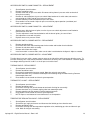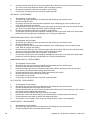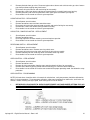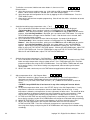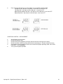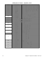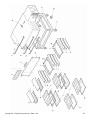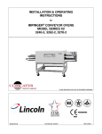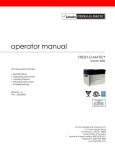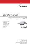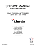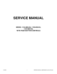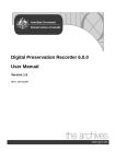
1
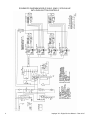
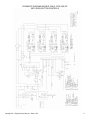
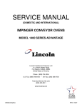
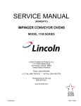
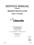
SERVICE MANUAL
(DOMESTIC & INTERNATIONAL)
IMPINGER X2 OVENS
WITH PUSH BUTTON CONTROLS
MODEL
3240-2, 3262-2, 3270-2
Lincoln Foodservice Products, LLC
1111 North Hadley Road
Fort Wayne, Indiana 46804
United States of America
Phone : (800) 374-3004
U.S. Fax: (888) 790-8193 • Int’l Fax: (260) 436-0735
Technical Service Hot Line
(800) 678-9511
www.lincolnfp.com
X2digservman
REV: 1/22/07
SEQUENCE OF OPERATION
IMPINGER X2 OVENS - DOMESTIC
WITH PUSH BUTTON CONTROLS
3240-2*
3240-2*
3262-2*
3262-2*
3270-2*
3270-2*
230VAC
230VAC
230VAC
230VAC
230VAC
230VAC
60 HZ.
60 HZ.
60 HZ.
60 HZ.
60 HZ.
60 HZ.
1 PHASE
3 PHASE
1 PHASE
3 PHASE
1 PHASE
3 PHASE
*NOTE:
Model number ending in TS indicates top belt is split belt
Model number ending in SB indicates bottom belt is split belt
Model number ending in SS indicates both belts are split belts
POWER SUPPLY
MAIN FAN CIRCUIT
BURNER CIRCUIT
TEMPERATURE CONTROL
CONVEYOR DRIVE
AUTOMATIC COOL DOWN
2
Electrical power to be supplied to the oven by a three conductor service for single phase
or a four conductor service for three phase.
Black conductor is hot.
Red conductor is hot.
Orange conductor is hot.
Green conductor is ground.
Power is permanently supplied to the normally open contacts of the main fan relay.
Power is also supplied, through a 3 amp. fuse, to the 30 minute time delay relay.
Closing the oven power switch enables the 30 minute time delay relay. The 30 minute
time delay relay supplies line voltage to the coil of the main fan relay. These normally
open contacts now close energizing the main fan motor. Closing the main power switch
also supplies power to the burner and conveyor circuits.
Closing the main power switch supplies line voltage to the oven control transformer. The
transformer’s secondary supplies 24VAC to the oven control and, through the burner
blower air pressure switch, to the burner control. When the burner control is supplied
with 24VAC, the pilot valve is energized and the igniter circuit is energized. Ignition
should now occur. After the pilot flame is proven, the main gas valve is energized.
Closing the main fan switch supplies line voltage to the oven control transformer. The
transformer’s secondary supplies 24VAC to the oven control. The oven control is set to
the desired temperature. The thermocouple will provide varying millivolts to the oven
control. The oven control supplies line voltage to the temperature regulation valve at
intermittent intervals to maintain desired temperature. The display on the oven control
will indicate when the temperature regulation valve is energized.
NOTE: The display also indicates oven temperature.
THE OVEN WILL CONTAIN BETWEEN TWO AND FOUR SEPARATE CONVEYOR
DRIVE SYSTEMS. THE SEQUENCE OF OPERATIONS WILL BE THE SAME FOR
EACH MOTOR SYSTEM.
Closing the main fan switch supplies line voltage, to the conveyor motor and to the
primary of the control transformer. Secondary voltage, 24VAC, is supplied to he oven
control. Setting the oven control to the desired time, outputs voltage, through a
reversing switch, to the conveyor motor.
NOTE: The conveyor control uses a hall effect sensor and magnet to prove operation of
the conveyor motor. If the conveyor motor is not running, “BELT JAM” is indicated on
the display.
When the oven is started, the 30 minute time delay relay is enabled, permitting the oven
fan to operate for approximately 30 minutes after the oven is shut off, to cool the oven.
When the oven is shut off, the 30 minute time delay relay will keep the coil of the main
fan relay closed for 30 minutes, maintaining operation of the main fan motor.
Impinger X2 – Digital Service Manual – Dom & Int’l
SEQUENCE OF OPERATION
IMPINGER X2 OVENS - INTERNATIONAL
WITH PUSH BUTTON CONTROLS
3240-2*
3262-2*
3270-2*
230VAC
230VAC
230VAC
50 HZ.
50 HZ.
50 HZ.
1 PHASE
1 PHASE
1 PHASE
*NOTE:
Model number ending in TS indicates top belt is split belt
Model number ending in SB indicates bottom belt is split belt
Model number ending in SS indicates both belts are split belts
POWER SUPPLY
MAIN FAN CIRCUIT
BURNER CIRCUIT
TEMPERATURE CONTROL
CONVEYOR DRIVE
AUTOMATIC COOL DOWN
Electrical power to be supplied to the oven by a three conductor service for single phase
or a four conductor service for three phase.
Black conductor is hot.
Red conductor is hot.
Orange conductor is hot.
Green conductor is ground.
Power is permanently supplied to the normally open contacts of the main fan relay.
Power is also supplied, through a 3 amp. fuse, to the 30 minute time delay relay.
Closing the oven power switch enables the 30 minute time delay relay. The 30 minute
time delay relay supplies line voltage to the coil of the main fan relay. These normally
open contacts now close energizing the main fan motor. Closing the main power switch
also supplies power to the burner and conveyor circuits.
Closing the oven power switch supplies line voltage, through the air pressure switch and
through the oven cavity hi-limit thermostat, to the burner control. The burner control
supplies line voltage to the burner blower motor. The normally open air pressure switch
closes upon sensing air pressure. The spark and pilot valve are now energized. Ignition
should now occur. After the pilot flame is proven, the main gas valve is energized.
Closing the main fan switch supplies line voltage, through a filter, to the oven control
transformer. The transformer’s secondary supplies 24VAC to the oven control. The oven
control is set to the desired temperature. The thermocouple will provide varying millivolts
to the oven control. The oven control supplies line voltage to the temperature regulation
valve at intermittent intervals to maintain desired temperature. The display on the oven
control will indicate when the temperature regulation valve is energized.
NOTE: The display also indicates oven temperature.
THE OVEN WILL CONTAIN BETWEEN TWO AND FOUR SEPARATE CONVEYOR
DRIVE SYSTEMS. THE SEQUENCE OF OPERATIONS WILL BE THE SAME FOR
EACH MOTOR SYSTEM.
Closing the main fan switch supplies line voltage, through a filter, to the conveyor motor
and, through a filter, to the primary of the control transformer. Secondary voltage,
24VAC, is supplied to he oven control. Setting the oven control to the desired time,
outputs voltage, through a reversing switch, to the conveyor motor.
NOTE: The conveyor control uses a hall effect sensor and magnet to prove operation of
the conveyor motor. If the conveyor motor is not running, “STALL” is indicated on the
display.
When the oven is started, the 30 minute time delay relay is enabled, permitting the oven
fan to operate for approximately 30 minutes after the oven is shut off, to cool the oven.
When the oven is shut off, the 30 minute time delay relay will keep the coil of the main
fan relay closed for 30 minutes, maintaining operation of the main fan motor.
Impinger X2 – Digital Service Manual – Dom & Int’l
3
SCHEMATIC DIAGRAM MODELS 3240-2, 3262-2, 3270-2 60 HZ.
WITH PUSH BUTTON CONTROLS
4
Impinger X2 – Digital Service Manual – Dom & Int’l
SCHEMATIC DIAGRAM MODELS 3262-2, 3270-2 50 HZ.
WITH PUSH BUTTON CONTROLS
Impinger X2 – Digital Service Manual – Dom & Int’l
5
TROUBLESHOOTING GUIDE - DOMESTIC
3240-2*
3240-2*
3262-2*
3262-2*
3270-2*
3270-2*
230VAC
230VAC
230VAC
230VAC
230VAC
230VAC
60 HZ.
60 HZ.
60 HZ.
60 HZ.
60 HZ.
60 HZ.
1 PHASE
3 PHASE
1 PHASE
3 PHASE
1 PHASE
3 PHASE
*NOTE:
Model number ending in TS indicates top belt is split belt
Model number ending in SB indicates bottom belt is split belt
Model number ending in SS indicates both belts are split belts
SYMPTOM
Oven fan will not run
POSSIBLE CAUSE
Incoming power supply
Fuse, 3 Amp, control
Fuse holder
Switch, oven fan
30 minute time delay relay
Relay, main fan
Overload protector, main fan
Main fan motor
Capacitor
Drive belt
Bearings, Fan shaft
6
EVALUATION
Check circuit breakers. Reset if required. Call power
co. if needed.
Check, replace if necessary.
Check, replace if necessary.
Check continuity between switch terminals. Replace
switch as needed.
Check for supply voltage to 30 minute time delay relay
at terminals #1 and #3. If no voltage is present, trace
wiring back to main power switch. If there is supply
voltage at terminals #1 and #3, check for output voltage
at terminals #2 and #3. If there is incoming voltage but
no output voltage, and the main power switch is on,
replace the 30 minute time delay relay.
Check for supply voltage to relay contacts, if no voltage
is present, trace wiring back to power supply. Check for
208/240VAC to the coil of the main fan relay. If no
voltage is present, trace wiring back to the 30 minute
time delay relay, check to be sure that the Overload
Protector contacts are closed. If contacts are open, see
“Overload Protector” below. If voltage is present, check
to insure relay contacts are closing. Replace relay as
needed.
Check to be sure overload contacts are closed. If not
closed, re-set overload. If contacts do not close,
replace overload protector. If contacts close, test for
proper operation. If the overload contacts do not stay
closed, and the amperage is below the overload
setting, replace the overload protector.
3240 should be set at 13A
3262 should be set at 18A
3270 should be set at 18A
Check for supply voltage at motor. If no voltage is
present, trace wiring back to the overload protector.
WITH POWER OFF: Check for opens, shorts or
grounds. Turn motor shaft to check for locked rotor.
Check for shorts or grounds.
WARNING: Capacitor has a stored charge, discharge
before testing.
Check for loose or broken drive belt. Adjust motor for
proper belt tension (maximum of 3/8-inch deflection), or
replace drive belt as needed.
Check for any damage or excessive wear on the shaft
bearings. Replace bearings as needed.
Impinger X2 – Digital Service Manual – Dom & Int’l
Oven will not heat
Gas supply
Manual gas shut off valve
Check for adequate gas supply to oven.
Check to see that the manual gas shut off valve is
open. Also, check flexible gas line connection for any
damage.
Main fan motor
Check for main fan operation. If it is not operating, refer
to “Oven fan will not run”.
Relay, main fan
Check for 208/240VAC supplied to relay terminal #13.
If voltage is not present, trace wiring back to power
supply. If voltage is present, check for 208/240VAC at
terminal #14. If there is no voltage at terminal #14, and
the relay is energized, replace the main fan relay.
Air pressure switch, Main fan
Check for 208/240VAC to the air pressure switch. If no
motor
voltage is present, trace wiring back to main fan switch.
This normally open switch should close when the main
fan is activated. Check air switch tube for blockage or
any obstructions, repair as needed. Refer to the
“Removal and installation” section for proper
adjustment of air pressure switch. Replace air pressure
switch as needed.
Hi-limit thermostat, oven cavity Terminals are normally closed. If open, reset
thermostat and retest. If thermostat will not hold for
maximum oven temperature, and oven is not exceeding
temperature setting, check for proper location of
capillary bulb in its spring holder. If the capillary checks
okay, replace the hi-limit thermostat.
Transformer, burner/control
Check for 208/240VAC supplied to primary of
transformer. If no voltage is present, trace wiring back
to the main fan switch. If voltage is present, check for
24VAC at transformer secondary.
NOTE: This is a dual secondary transformer, it is
important to check BOTH 24VAC outputs.
If there is primary voltage but no secondary voltage,
replace burner/control transformer.
Motor, burner blower
Check for 208/240VAC supplied to the burner blower
motor. If no voltage is present, trace wiring back to the
hi-limit thermostat. If voltage is present, and the motor
is not turning, check for opens, shorts or grounds.
WITH POWER OFF: Check for locked rotor.
Replace burner blower motor as needed.
Air pressure switch, burner
Check for 24VAC to the air pressure switch. If no
blower motor
voltage is present, trace wiring back to the
burner/control transformer. This normally open switch
should close when the burner blower motor is
activated. Check air switch tube for blockage or any
obstructions, repair as needed. Refer to the “Removal
and installation” section for proper adjustment of air
pressure switch. Replace air pressure switch as
needed.
Burner control
Check for 24VAC supply to the ignition control. If no
voltage is present, trace wiring back to centrifugal
switch of burner blower motor. If voltage is present,
check for 24VAC at pin #3 and ground (pilot valve).
NOTE: The Honeywell ignition control has a 30 second
pre-purge (time delay) built in. If voltage is not present,
replace ignition control. If the pilot valve is energized,
check to see that the high voltage igniter circuit is also
energized. To check, turn power off, disconnect the
igniter lead from the ignition control. Turn power on. If
no spark is visible, replace burner control. If a spark is
visible at burner control, proceed.
Pilot valve
Check for 24VAC supplied to pilot valve. If no voltage is
Impinger X2 – Digital Service Manual – Dom & Int’l
7
No pilot flame
Pilot tube
Pilot orifice
Burner igniter
Low flame is on, but no main
flame
NOTE: Flame should be
on at this time
Transformer, burner/control
Oven control
Thermocouple probe
Oven control
8
present, trace wiring back to burner control. If voltage is
present, check for gas pressure at the pilot line
connection. If no gas pressure is present during
ignition, check for any blockage in the assembly. If
there are no obstructions, and there is gas supplied to
the oven, replace the gas valve.
If the ignition control is supplied with 24VAC and the
pilot valve and igniter circuits are energized, visually
check for a pilot flame. This may be done by looking
through the inspection view port on the end of the
burner. If no pilot flame is visible, check the pilot tube.
Check for gas pressure at the pilot tube. Disconnect
pilot tube at the burner And connect manometer to pilot
tube. If no gas pressure is present during ignition,
check for blockage of the pilot tube. If the pilot tube is
clear, proceed.
If there is gas pressure at the pilot tube, check the pilot
orifice for blockage or obstructions. Replace pilot orifice
as needed.
Check the burner igniter head for any damage or
obstructions also check for frayed or broken wire.
Check spark gap, gap should be 3/32” If there is visible
damage, replace burner igniter.
Check for 208/240VAC supplied to primary of
transformer. If no voltage is present, trace wiring back
to the main fan switch. If voltage is present, check for
24VAC at transformer secondary.
NOTE: This is a dual secondary transformer, it is
important to check BOTH 24VAC outputs.
If there is primary voltage but no secondary voltage,
replace burner/control transformer.
Check for 24VAC supply to oven control. If no voltage
is present, trace wiring back to control transformer. If
24VAC is present, check for a read-out on the display.
If there is 24VAC supplied, but there is no read-out on
the display, replace oven control. If there is a read-out
on the control, set the control to maximum temperature
(see Installation operations manual for temperature
adjustment). With the control set at maximum
temperature, check for 208/240VAC at the temperature
regulation valve. If there is voltage at the temperature
regulation valve, proceed to “Temperature regulation
valve” for next check. If there is no voltage at the
temperature regulation valve, trace wiring back to the
oven control. If there is no voltage output at the oven
control, check the read-out on the oven control. If the
control reads “PROBE FAIL”, this indicates that the
thermocouple has failed or become disconnected from
the oven control.
Check to be sure that the thermocouple is securely
connected to the oven control. If the thermocouple is
connected to the oven control, and the control indicates
“PROBE FAIL”, disconnect the thermocouple from the
oven control and measure the resistance of the
thermocouple. The thermocouple should read approx.
11Ω. If these readings are not achieved, replace the
thermocouple. If these readings are correct, proceed.
If the thermocouple checks good, but the oven control
display indicates that there is a thermocouple failure,
Impinger X2 – Digital Service Manual – Dom & Int’l
Intermittent heating
Conveyor will not run
replace the oven control. If the oven control indicates a
temperature reading, but the oven will not heat,
proceed.
Main gas valve
Check to see that the switch on the valve is in the “ON”
position. Check for 24VAC supplied to main valve. If
there is voltage present, check to see that valve is
opening. Connect manometer to pressure tap on outlet
side of valve. If there is voltage to the valve, but no
output gas pressure, replace the valve.
Temperature regulation valve Check for 208/240VAC at temperature regulation valve.
If no voltage is present, trace wiring back to electronic
temperature control. If voltage is present, listen for
valve to open and close. Also check for opens or shorts
in the operating coil. Replace temperature regulation
valve as needed.
Oven control
Check for 3 – 24VDC from the oven control at terminals
#J2-6 and J2-9. If there is no output voltage, replace
oven control. If there is output voltage,
Proceed.
Modulating valve
Check for 3-24VDC at the modulating valve. If no
voltage is present, trace wiring back to the oven
control. If voltage is present, listen for valve to open
and close. Also check for opens or shorts in the
operating coil. Replace modulating valve as needed.
Thermal/Overload of main fan The main fan motor and burner blower motor are
and burner blower motors
equipped with internal thermal protection and will cease
to operate if overheating occurs. As the motors overheat and then cool, this will cause the units to cycle on
and off intermittently. Improper ventilation or lack of
preventive maintenance may cause this. Also, most of
the problems listed under “Oven will not heat” can
cause intermittent failure.
NOTE: The ovens may contain two, three or four conveyor drive systems using like
components. The trouble shooting sequence will be the same for each of the conveyor
drive systems
Power supply
Switch, oven power
Relay, main fan
Transformer, burner/control
Switch, conveyor reversing
Conveyor motor
Impinger X2 – Digital Service Manual – Dom & Int’l
Check circuit breakers, reset if required. Check power
plug to be sure it is firmly in receptacle. Measure
incoming power, call power co. if needed.
Check continuity between switch terminals. Replace
switch as needed.
Check for 120VAC supplied to relay terminal #13. If
voltage is not present, trace wiring back to power
supply. If voltage is present, check for 120VAC at
terminal #14. If there is no voltage at terminal #14, and
the relay is energized, replace the main fan relay.
Check for 208/240VAC supplied to primary of
transformer. If no voltage is present, trace wiring back
to the main fan switch. If voltage is present, check for
24VAC at transformer secondary.
NOTE: This is a dual secondary transformer, it is
important to check BOTH 24VAC outputs.
If there is primary voltage but no secondary voltage,
replace burner/control transformer.
Check for continuity between switch terminals. Replace
switch as needed.
Check for 208/240VAC supplied to the motor. I no
voltage is present, trace wiring back to the reversing
switch. If voltage is present, check motor windings for
opens or shorts.
9
Capacitor, conveyor motor
Conveyor
Oven control
Conveyor motor runs, but there
is no speed display
NOTE: Display will indicate
“STALL”
Oven control
Motor, conveyor
Oven control
10
WITH POWER OFF: Check the motor windings as
follows:
Grey to Black – 114 ohm approx.
Grey to Brown – 114 ohm approx.
Brown to Black – 228 ohm approx.
If any of the above fail, replace motor.
Check for shorts or grounds. Replace capacitor as
needed.
WARNING: Capacitor has a stored charge, discharge
before testing.
Check for any mechanical problems in the conveyor
assembly. Check for damaged or torn belting. Check
conveyor shaft bearings for damage or excessive wear.
Repair or replace conveyor components as needed.
If there is voltage supplied to the motor, and the motor,
capacitor, and reversing switch check good, replace the
oven control.
Check output voltage from oven control to hall effect
sensor (sensor is located in conveyor motor). Measure
voltage at the motor connector, red wire and yellow
wire. Voltage should be approx. 10VDC. If no voltage is
present, trace wiring back to the oven control. If there is
no voltage output present at the oven control, replace
the oven control.
If there is voltage supplied to the hall effect sensor,
check for a frequency output from the hall effect
sensor. Measure frequency across the yellow and white
wires at the motor connector. Frequency readings
should be between 15 Hz-500 Hz. If these readings are
not achieved, replace conveyor motor. If these readings
are achieved, proceed.
If the hall effect sensor readings are correct, but there
is no speed indicated on the display, replace the
control.
Impinger X2 – Digital Service Manual – Dom & Int’l
TROUBLESHOOTING GUIDE - INTERNATIONAL
3240-2*
3262-2*
3270-2*
230VAC
230VAC
230VAC
50 HZ.
50 HZ.
50 HZ.
1 PHASE
1 PHASE
1 PHASE
*NOTE:
Model number ending in TS indicates top belt is split belt
Model number ending in SB indicates bottom belt is split belt
Model number ending in SS indicates both belts are split belts
SYMPTOM
Oven fan will not run
POSSIBLE CAUSE
Incoming power supply
Fuse, 3 Amp, control
Fuse holder
Switch, oven fan
30 minute time delay relay
Relay, main fan
Overload protector, main fan
Main fan motor
Capacitor
Drive belt
Bearings, Fan shaft
Oven will not heat
Gas supply
Manual gas shut off valve
Impinger X2 – Digital Service Manual – Dom & Int’l
EVALUATION
Check circuit breakers. Reset if required. Call power
co. if needed.
Check, replace if necessary.
Check, replace if necessary.
Check continuity between switch terminals. Replace
switch as needed.
Check for supply voltage to 30 minute time delay relay
at terminals #1 and #3. If no voltage is present, trace
wiring back to fuse holder. If there is supply voltage at
terminals #1 and #3, check for output voltage at
terminals #2 and #3. If there is incoming voltage but no
output voltage, and the main power switch is on,
replace the 30 minute time delay relay.
Check for supply voltage to relay contacts, if no voltage
is present, trace wiring back to power supply. Check for
supply voltage to the coil of the main fan relay. If no
voltage is present, trace wiring back to the 30 minute
time delay relay, check to be sure that the Overload
Protector contacts are closed. If contacts are open, see
“Overload Protector” below. If voltage is present, check
to insure relay contacts are closing. Replace relay as
needed.
Check to be sure overload contacts are closed. If not
closed, re-set overload. If contacts do not close,
replace overload protector. If contacts close, test for
proper operation. If the overload contacts do not stay
closed, and the amperage is below the overload
setting, replace the overload protector.
3240 should be set at 13A
3262 should be set at 18A
3270 should be set at 18A
Check for supply voltage at motor. If no voltage is
present, trace wiring back to the overload protector.
WITH POWER OFF: Check for opens, shorts or
grounds. Turn motor shaft to check for locked rotor.
Check for shorts or grounds.
WARNING: Capacitor has a stored charge, discharge
before testing.
Check for loose or broken drive belt. Adjust motor for
proper belt tension (maximum of 3/8-inch deflection), or
replace drive belt as needed.
Check for any damage or excessive wear on the shaft
bearings. Replace bearings as needed.
Check for adequate gas supply to oven.
Check to see that the manual gas shut off valve is
open. Also, check flexible gas line connection for any
11
damage.
Check for main fan operation. If it is not operating, refer
to “Oven fan will not run”.
Relay, main fan
Check for supply voltage to relay terminal #13. If
voltage is not present, trace wiring back to power
supply. If voltage is present, check for supply voltage at
terminal #14. If there is no voltage at terminal #14, and
the relay is energized, replace the main fan relay.
Air pressure switch, Main fan
Check for supply voltage to the air pressure switch. If
motor
no voltage is present, trace wiring back to main fan
switch. This normally open switch should close when
the main fan is activated. Check air switch tube for
blockage or any obstructions, repair as needed. Refer
to the “Removal and installation” section for proper
adjustment of air pressure switch. Replace air pressure
switch as needed.
Hi-limit thermostat, oven cavity Terminals are normally closed. If open, reset
thermostat and retest. If thermostat will not hold for
maximum oven temperature, and oven is not exceeding
temperature setting, check for proper location of
capillary bulb in its spring holder. If the capillary checks
okay, replace the hi-limit thermostat.
Burner control
Check for supply voltage to burner control at terminal
#1 and Neutral. If no voltage is present, trace wiring
back to hi-limit thermostat. If voltage is present, check
for supply voltage to burner blower motor at terminal #8
and neutral. If no voltage is present, wait thirty
seconds, reset burner control, and re-try. If the above
fails, replace burner control.
Burner reset switch.
Switch is normally open, check to see that the switch
closes when reset button is pushed. Replace switch as
needed.
Motor, burner blower
Check for supply voltage to the burner blower motor. If
no voltage is present, trace wiring back to the burner
control. If voltage is present, and the motor is not
turning, check for opens, shorts or grounds.
WITH POWER OFF: Check for locked rotor.
Replace burner blower motor as needed.
Air pressure switch, burner
Check for air pressure switch to be switching from “NC”
blower motor
to “NO”. Check for air tube blockage or misalignment.
Replace air pressure switch as needed.
Burner control
A pre-purge time of 30 – 60 seconds occurs after
burner blower motor starts. Check for high voltage
spark output from the burner control. If there is no high
voltage spark output, check reset button for the burner
control. If there is still no high voltage output, replace
the burner control.
Igniter/sensor assembly
Check for visible damage to the igniter/sensor
assembly. If there is visible damage, replace
components as needed. If there is no visible damage to
the components, and there is no spark, replace the
igniter/sensor assembly. Also check for damaged wires
in the burner tube. Replace components as needed.
Burner control
Gas valve should open as the burner control generates
the high voltage spark. Check for supply voltage to pilot
valve at terminal #5 and neutral. If no voltage is
present, check reset button for the burner control. If
there is still no voltage the pilot valve, replace burner
control
Gas valve
Check for supply voltage at the pilot valve. If no voltage
is present, trace wiring back to the burner control. If
Impinger X2 – Digital Service Manual – Dom & Int’l
Main fan motor
12
Pilot tube
Pilot orifice
Flame will not stay on
Flame sensor
Power supply
Burner control
Low flame is on, but no main
flame
NOTE: Flame should be
on at this time
Transformer, control
Oven control
Thermocouple probe
Impinger X2 – Digital Service Manual – Dom & Int’l
there is voltage, connect a manometer to the pressure
tap fitting on the gas valve. If there is voltage to the
pilot valve, but there is no gas pressure, replace gas
valve.
Check for gas pressure at pilot tube. Disconnect pilot
tube at burner and connect manometer. If there is no
gas pressure, check for blockage in pilot tube. Repair
or replace tube as needed.
If there is gas pressure at the pilot tube, check the pilot
orifice for blockage or obstructions. Replace pilot orifice
as needed.
To check flame sensor operation, connect a digital
multimeter (capable of measuring D.C. Microamps)
between the flame sensor wire and the flame sensor
connection on the ignition control (terminal #3). Flame
sensor current is to be 0.7 microamp, minimum. If
these readings are not achieved, replace igniter/sensor
assembly. Also check for any type of damage to flame
sensor wire and connections.
NOTE: The D.C. microamp test must be conducted
with the oven in low flame operation.
Set the temperature to the lowest temperature setting.
If there is sufficient microamp current, but the flame will
not stay lit, check for proper polarity of the power
supply.
If there is sufficient microamp current, and there is
proper polarity of the power supply, but the burner will
not stay lit, check the reset button for the burner
control. If the above test is okay, replace the burner
control.
Check for supply voltage to primary of control
transformer. If no voltage is present, trace wiring back
to the main fan switch. If voltage is present, check for
24VAC at transformer secondary.
If there is primary voltage but no secondary voltage,
replace burner/control transformer.
Check for 24VAC supply to oven control. If no voltage
is present, trace wiring back to control transformer. If
24VAC is present, check for a read-out on the display.
If there is 24VAC supplied, but there is no read-out on
the display, replace oven control. If there is a read-out
on the control, set the control to maximum temperature
(see Installation operations manual for temperature
adjustment). With the control set at maximum
temperature, check for supply voltage at the
temperature regulation valve. If there is voltage at the
temperature regulation valve, proceed to “Temperature
regulation valve” for next check. If there is no voltage at
the temperature regulation valve, trace wiring back to
the oven control. If there is no voltage output at the
oven control, check the read-out on the oven control. If
the control reads “PROBE FAIL”, this indicates that the
thermocouple has failed or become disconnected from
the oven control.
Check to be sure that the thermocouple is securely
connected to the oven control. If the thermocouple is
connected to the oven control, and the control indicates
“PROBE FAIL”, disconnect the thermocouple from the
oven control and measure the resistance of the
13
Intermittent heating
Conveyor will not run
thermocouple. The thermocouple should read approx.
11Ω. If these readings are not achieved, replace the
thermocouple. If these readings are correct, proceed.
Oven control
If the thermocouple checks good, but the oven control
display indicates that there is a thermocouple failure,
replace the oven control. If the oven control indicates a
temperature reading, but the oven will not heat,
proceed.
Main gas valve
Check to see that the switch on the valve is in the “ON”
position. Check for supply voltage to main valve. If
there is voltage present, check to see that valve is
opening. Connect manometer to pressure tap on outlet
side of valve. If there is voltage to the valve, but no
output gas pressure, replace the valve.
Temperature regulation valve Check for supply voltage at temperature regulation
valve. If no voltage is present, trace wiring back to
electronic temperature control. If voltage is present,
listen for valve to open and close. Also check for opens
or shorts in the operating coil. Replace temperature
regulation valve as needed.
Oven control
Check for 3 – 24VDC from the oven control at terminals
#J2-6 and J2-9. If there is no output voltage, replace
oven control. If there is output voltage,
Proceed.
Modulating valve
Check for 3-24VDC at the modulating valve. If no
voltage is present, trace wiring back to the oven
control. If voltage is present, listen for valve to open
and close. Also check for opens or shorts in the
operating coil. Replace modulating valve as needed.
Thermal/Overload of main fan The main fan motor and burner blower motor are
and burner blower motors
equipped with internal thermal protection and will cease
to operate if overheating occurs. As the motors overheat and then cool, this will cause the units to cycle on
and off intermittently. Improper ventilation or lack of
preventive maintenance may cause this. Also, most of
the problems listed under “Oven will not heat” can
cause intermittent failure.
NOTE: The ovens may contain two, three or four conveyor drive systems using like
components. The trouble shooting sequence will be the same for each of the conveyor
drive systems
Power supply
Switch, oven power
Relay, main fan
Transformer, control
Switch, conveyor reversing
Conveyor motor
14
Check circuit breakers, reset if required. Check power
plug to be sure it is firmly in receptacle. Measure
incoming power, call power co. if needed.
Check continuity between switch terminals. Replace
switch as needed.
Check for supply voltage to relay terminal #13. If
voltage is not present, trace wiring back to power
supply. If voltage is present, check for supply voltage at
terminal #14. If there is no voltage at terminal #14, and
the relay is energized, replace the main fan relay.
Check for supply voltage to primary of transformer. If
no voltage is present, trace wiring back to the main fan
switch. If voltage is present, check for 24VAC at
transformer secondary.
If there is primary voltage but no secondary voltage,
replace burner/control transformer.
Check for continuity between switch terminals. Replace
switch as needed.
Check for supply voltage to the motor. If no voltage is
Impinger X2 – Digital Service Manual – Dom & Int’l
Capacitor, conveyor motor
Conveyor
Oven control
Conveyor motor runs, but there
is no speed display
NOTE: Display will indicate
“STALL”
Oven control
Motor, conveyor
Oven control
Impinger X2 – Digital Service Manual – Dom & Int’l
present, trace wiring back to the reversing switch. If
voltage is present, check motor windings for opens or
shorts.
WITH POWER OFF: Check the motor windings as
follows:
Grey to Black - 114 ohm approx.
Grey to Brown - 114 ohm approx.
Brown to Black - 228 ohm approx.
If any of the above fail, replace motor.
Check for shorts or grounds. Replace capacitor as
needed.
WARNING: Capacitor has a stored charge, discharge
before testing.
Check for any mechanical problems in the conveyor
assembly. Check for damaged or torn belting. Check
conveyor shaft bearings for damage or excessive wear.
Repair or replace conveyor components as needed.
If there is voltage supplied to the motor, and the motor,
capacitor, and reversing switch check good, replace the
oven control.
Check output voltage from oven control to hall effect
sensor (sensor is located in conveyor motor). Measure
voltage at the motor connector, red wire and yellow
wire. Voltage should be approx. 10VDC. If no voltage is
present, trace wiring back to the oven control. If there is
no voltage output present at the oven control, replace
the oven control.
If there is voltage supplied to the hall effect sensor,
check for a frequency output from the hall effect
sensor. Measure frequency across the yellow and white
wires at the motor connector. Frequency readings
should be between 15 Hz-500 Hz. If these readings are
not achieved, replace conveyor motor. If these readings
are achieved, proceed.
If the hall effect sensor readings are correct, but there
is no speed indicated on the display, replace the
control.
15
REMOVAL, INSTALLATION & ADJUSTMENTS
IMPINGER X2 SERIES OVENS
CAUTION!
BEFORE REMOVING OR INSTALLING ANY COMPONENT IN THE IMPINGER X2
OVEN BE SURE TO DISCONNECT ELECTRICAL POWER AND GAS SUPPLY
MOTOR, MAIN FAN - REPLACEMENT
1.
2.
3.
4.
5.
6.
Shut off power at main breaker.
Remove control box cover and control box rear cover.
Disconnect motor wiring and mark all wiring for reassembly.
Remove V-belt by loosening the four bolts on the motor mount plate and the two belt tensioning bolts.
Remove motor and motor mount assembly. Remove motor from motor mount. Remove pulley from motor
and install pulley on new motor.
Reassemble in reverse order and check system operation. Be sure to check for proper tension on drive
belt. Adjust tension bolts until there is no more than 3/8 inch deflection at the halfway point between the
motor pulley and the driven pulley.
SHAFT AND BLOWER WHEEL – REPLACEMENT
1.
2.
3.
4.
5.
6.
Shut off power at main breaker.
Remove cover panels form both sides.
Remove back.
Unbolt blower housings
Remove thermocouple from mount
Remove flanges from blower housing
( mark position of flange for replacement)
7. Unbolt air return panels from inside top
8. Remove sheet metal from plenum
16
Impinger X2 – Digital Service Manual – Dom & Int’l
9. Remove burner tube bracket
and Burner tube.
To remove burner tube,
Remove cap from idle end of
Oven wall and remove burner tube.
10. Measure distance from end of shaft to the collar
11. of blower wheel. Loosen blower wheels from shaft.
(1/4" allen screws - use liquid wrench)
Push blower wheels toward idle end.
12. Loosen and remove idle and drive end bearings.
13. Remove shaft and blower wheel assembles.( measure length of
shaft extension from oven wall. Use same measurement when
putting new shaft in)
Remove shaft through idle end of oven.
13.NOTE: When putting new shaft and blower wheels back in, the wheels will have to be removed from the shaft.
It is important to mark the blowers left and right and to mark the positioning of the blowers on the shaft so as to
maintain spacing and balance.
When replacing the burner tube, the top
of the holes in the burner tube should be
12 3/8" from the bottom of the oven.
1. When replacing the expansion bearing in
the drive end, be sure the yoke of the bearing
is pushed as far as possible towards the
oven wall and tightened on the shaft. This
will allow the bearing to expand outward.
Align pulley on drive end of shaft with
pulley on drive motor. Grease bearings
before starting oven.
Impinger X2 – Digital Service Manual – Dom & Int’l
17
RELAY, MAIN FAN, - REPLACEMENT
1.
2.
3.
4.
5.
6.
Shut off power at main breaker.
Remove control box cover.
Disconnect all wiring from relay and mark all wiring for reassembly.
Remove main relay and overload protector.
Remove overload protector from main relay and mount overload protector on new relay.
Reassemble in reverse order and check system for proper operation.
TIMER, 30 MINUTE COOL DOWN – REPLACEMENT
1.
2.
3.
4.
5.
Shut off power at main breaker.
Remove control box cover.
Disconnect all wiring from 30-minute cool down timer and mark all wires for reassembly.
Remove one mounting bolt and remove 30-minute cool down timer.
Reassemble in reverse order and check system operation.
FUSE HOLDER – REPLACEMENT
1.
2.
3.
4.
5.
Shut off power at main breaker.
Remove control box cover.
Disconnect wiring from fuse holder and mark all wiring for reassembly.
Remove mounting nut from fuse holder and remove fuse holder.
Reassemble in reverse order and check system operation.
SWITCH, ON/OFF – REPLACEMENT
1.
2.
3.
4.
5.
Shut off power at main breaker.
Remove control box cover.
Disconnect wiring from switch and mark all wiring for reassembly.
Remove switch by depressing spring clips on sides of switch. Push switch out.
Reassemble in reverse order and check system operation.
MOTOR, BURNER BLOWER – REPLACEMENT
1.
2.
3.
4.
Shut off power at main breaker.
Remove control box cover and front control box cover.
Disconnect wiring from motor. Mark all wiring for reassembly.
Remove three mounting screws and remove burner blower motor assembly.
Reassemble in reverse order and check system operation. Verify Air Mixture Disc is set to
0.75” ± 3/16 (24 – 14mm).
TRANSFORMER, BURNER/CONTROL – REPLACEMENT
1.
2.
3.
4.
5.
Shut off power at main breaker.
Remove control box cover.
Disconnect wiring from burner/control transformer and mark all wiring for reassembly.
Remove two mounting screws and remove burner/control transformer.
Reassemble in reverse order and check system operation.
BURNER CONTROL – REPLACEMENT
1.
2.
3.
4.
5.
18
Shut off power at main breaker.
Remove control box cover
Disconnect wiring from burner control and mark all wiring for reassembly.
Remove mounting screws and remove burner control.
Reassemble in reverse order and check system operation.
Impinger X2 – Digital Service Manual – Dom & Int’l
AIR PRESSURE SWITCH, MAIN FAN MOTOR – REPLACEMENT
1.
2.
3.
4.
5.
6.
Shut off power at main breaker.
Remove control box cover.
Remove cover from air pressure switch. Disconnect wiring from air pressure switch and mark all
wiring for reassembly.
Remove air switch tube from air pressure switch. Note location of air switch tube, tube must be
connected to the “HIGH” port of the air pressure switch.
Remove mounting screws and remove air pressure switch.
Reassemble in reverse order. Adjust air pressure switch for proper operation (see below) and
check system operation.
AIR PRESSURE SWITCH, MAIN FAN MOTOR – ADJUSTMENT
1.
2.
3.
4.
Start the oven. After the burner ignites, turn the air pressure switch adjustment screw Clockwise
until the burner shuts off .
Turn the adjustment screw Counterclockwise until the burner ignites, plus one full turn.
Seal adjustment screw with nail polish.
Replace cover on air pressure switch.
AIR PRESSURE SWITCH, BURNER MOTOR – REPLACEMENT
1.
2.
3.
4.
5.
Remove control panel top.
Disconnect wires from switch making note of wire number and location for reinstallation.
Remove air tube from switch assembly.
Remove switch from wire hangar.
Install new switch in reverse order, make sure air tube is not blocked or misaligned. Adjust as needed.
AIR PRESSURE SWITCH, BURNER MOTOR – ADJUSTMENT
To adjust the air pressure switch, remove snap-on cover on the side of the switch to expose adjusting screw. To
increase sensitivity, turn screw counter clockwise; to decrease sensitivity, turn screw clockwise. Check for proper
line voltage switching from N.C. to N.O. as the air pressure switch closes.
THERMOCOUPLE – REPLACEMENT
1.
2.
3.
4.
5.
Shut off power at main breaker.
Remove control box cover.
Disconnect thermocouple from oven control. Note wire colors for reassembly.
Remove oven back assy. Remove thermocouple from mounting flange in blower housing. Remove
thermocouple from oven.
Reassemble in reverse order and check system operation.
THERMOSTAT, HI-LIMIT – REPLACEMENT
1.
2.
3.
4.
5.
6.
7.
Shut off power at main breaker.
Remove control box cover.
Disconnect all wiring from hi-limit thermostat and mark all wiring for reassembly.
Remove oven back assy. Remove capillary tube from mounting bracket.
Remove mounting nut and remove hi-limit thermostat from oven.
Reassemble in reverse order and check system operation.
NOTE: Depress reset button to insure thermostat is set for operation.
TEMPERATURE REGULATION VALVE – REPLACEMENT
1.
2.
3.
4.
Shut off power at main breaker.
Shut off the gas supply to the oven and disconnect the flexible gas hose from the oven.
Remove control box cover.
Disconnect all wiring from the temperature regulation valve, modulating gas valve and the main gas
valve. Mark all wiring for reassembly.
Impinger X2 – Digital Service Manual – Dom & Int’l
19
5.
6.
7.
Remove pilot tube from gas valve. Disconnect pipe union at the burner and at the inlet side of the main
gas valve. Loosen pipe clamp and remove valves and piping assembly.
Remove piping from old valve and reassemble in reverse order.
Check all gas line fittings for leaks and check system operation.
GAS VALVE – REPLACEMENT
1.
2.
3.
4.
5.
6.
7.
Shut off power at main breaker.
Shut off the gas supply to the oven and disconnect the flexible gas hose from the oven.
Remove control box cover.
Disconnect all wiring from the temperature regulation valve, modulating gas valve and the main gas
valve. Mark all wiring for reassembly.
Remove pilot tube from gas valve. Disconnect pipe unions at the burner and at the inlet side of the main
gas valve. Loosen pipe clamp and remove valves and piping assembly.
Remove piping from old valve and reassemble in reverse order.
Check all gas line fittings for leaks and adjust manifold pressure on gas valve. Refer to the specification
plate on the oven for proper gas manifold pressure. Check system operation.
MODULATING GAS VALVE – REPLACEMENT
1.
2.
3.
4.
5.
6.
7.
Shut off power at main breaker.
Shut off the gas supply to the oven and disconnect the flexible gas hose from the oven.
Remove control box cover.
Disconnect all wiring from the temperature regulation valve, modulating gas valve and the main gas
valve. Mark all wiring for reassembly.
Remove pilot tube from gas valve. Disconnect pipe unions at the burner and at the inlet side of the main
gas valve. Loosen pipe clamp and remove valves and piping assembly.
Remove piping from old valve and reassemble in reverse order.
Check all gas line fittings for leaks and adjust manifold pressure on gas valve. Refer to the specification
plate on the oven for proper gas manifold pressure. Check system operation.
MAIN BURNER ORIFICE – REPLACEMENT
1.
2.
3.
4.
5.
6.
7.
8.
Shut off power at main breaker.
Shut off the gas supply to the oven and disconnect the flexible gas hose from the oven.
Remove control box cover and control box front cover.
Remove pilot tube from gas valve. Disconnect pipe union at burner, loosen pipe union at inlet to gas
valve, loosen pipe clamp and move piping away from burner.
Remove two mounting nuts from burner flange and remove burner flange.
Remove main burner orifice from the burner flange.
Reassemble in reverse order.
Check all gas line fittings for leaks and check system operation.
PILOT ORIFICE – REPLACEMENT
1.
2.
3.
4.
5.
6.
7.
8.
Shut off power at main breaker.
Shut off the gas supply to the oven and disconnect the flexible gas hose from the oven.
Remove control box cover and control box front cover.
Remove pilot tube from gas valve. Disconnect pipe union at burner and at inlet to main gas valve. Loosen
pipe clamp and move piping away from burner.
Disconnect wiring from burner and mark wiring for reassembly.
Remove four screws from burner end plate and remove burner assembly from burner housing.
Remove pilot tube from igniter assembly and remove pilot orifice.
Reassemble in reverse order. Check all gas line fittings for leaks. Check system operation.
SPARK IGNITER – REPLACEMENT
1.
2.
3.
20
Shut off power at main breaker.
Shut off the gas supply to the oven and disconnect the flexible gas hose from the oven.
Remove control box cover and control box front cover.
Impinger X2 – Digital Service Manual – Dom & Int’l
4.
5.
6.
7.
8.
Remove pilot tube from gas valve. Disconnect pipe union at burner and at inlet to main gas valve. Loosen
pipe clamp and move piping away from burner.
Disconnect wiring from burner and mark wiring for reassembly.
Remove four screws from burner end plate and remove burner assembly from burner housing.
Remove pilot tube, pilot shield and pilot orifice from spark igniter and remove spark igniter.
Reassemble in reverse order and check system operation.
CONVEYOR MOTOR – REPLACEMENT
1.
2.
3.
4.
5.
Shut off power at main breaker.
Remove control box cover and front control box cover.
Disconnect wiring from the conveyor motor assembly and mark all wiring for reassembly.
Remove four screws and remove conveyor motor assembly.
Reassemble in reverse order and check system operation.
CAPACITOR, CONVEYOR MOTOR – REPLACEMENT
1.
2.
3.
4.
Shut off power at main breaker.
Remove control box cover.
Discharge capacitor. Remove mounting screw and replace capacitor.
Reassemble in reverse order and check system operation.
REVERSING SWITCH – REPLACEMENT
1.
2.
3.
4.
5.
Shut off power at main breaker.
Remove control box cover. Remove reversing switch cover.
Disconnect wiring from reversing switch and mark all wiring for reassembly.
Remove mounting nut from reversing switch and remove reversing switch.
Reassemble in reverse order and check system operation.
OVEN CONTROL – REPLACEMENT
1.
2.
3.
4.
5.
Shut off power at main breaker.
Remove control box cover.
Remove all wiring connections from the oven control and mark all wires for reassembly.
Remove oven control by pulling control from the mounting pins. Remove control from oven.
Reassemble in reverse order and set the new control for the proper operating mode. See below for set-up
procedure:
OVEN CONTROL - PROGRAMMING
NOTES: All bake times should be within 10 seconds of set bake time, cavity temperature should be calibrated to
within 5° of set temperature. For temperature calibration, allow oven temperature to stabilize for, at minimum, 30
minutes. Before checking conveyor speed, allow conveyor to run for 10 minutes.
1.
BEFORE APPLYING POWER TO OVEN, ENSURE PROPER VOLTAGE JUMPER SETTING FOR 120V
or 240V, AND THAT THE 50HZ / 60HZ JUMPER SETTING IS CORRECT. JUMPERS ARE LOCATED
ON CONVEYOR CONTROL BOARDS.
Impinger X2 – Digital Service Manual – Dom & Int’l
21
22
2.
To initialize a new control, hold the two center buttons in, then turn unit on.
Release buttons.
A. Select the correct oven model number (e.g. 3240, 3262, or 3270) by toggling the UP or DOWN
buttons. When correct model # is selected, press the TEMP button to store.
B. Select the proper belt configuration for this oven by toggling the UP or DOWN buttons. Press the
TEMP button to store.
C. Allow control sufficient time to update programming. Shut off main fan switch. Initialization of control
is now complete.
3.
Set digital control for proper temperature scale – F or C
A. Press and hold the 2 RH buttons to enter Sub-Level program. A prompt will be displayed
“Technicians Only.” After a couple of seconds a second prompt will say “Please Release
Buttons.” After releasing the buttons, quickly press the TIME button and the UP button to enter the
program. After Sub Program Menu is displayed, press and release the TEMP button. Pressing the
UP or DOWN buttons will toggle choices between F and C. After desired scale is selected, allow
control to go into normal run mode.
B. Press and hold the 2 RH buttons to enter Sub-Level program. A prompt will be displayed
“Technicians Only.” After a couple of seconds a second prompt will say “Please Release
Buttons.” After releasing the buttons, quickly press the TIME button and the UP button to enter the
program. After Sub Program Menu is displayed, press temp. button in steps until BANDWITH
appears. Adjust with the UP and DOWN buttons to a BANDWITH setting of 6. Press the TEMP
button in steps until THE CUTOUT VOLTAGE appears. With the UP and DOWN buttons, adjust THE
CUTOUT VOLTAGE to 3.0. Press the TEMP button in steps until THE CUT IN VOLTAGE appears.
With the UP and DOWN buttons, adjust THE CUT IN VOLTAGE to 4.5.
4.
Set bake time and oven temperature – Set Point Menu
A. Press and hold the 2 LH buttons to enter Set Point program. Once in Set Point program, press TEMP
button and adjust temperature using up or down arrows. Press TIME button while still in Set Point
program and adjust time using the UP or DOWN buttons. Pressing TIME or TEMP button will show
the respective setting. Once desired settings are programmed, allow control to go into normal
running mode.
B. While in this mode, continue to press the TIME button to toggle between different conveyors.
5.
Adjust temperature offset – Sub Program Menu
A. Follow the instructions in Step 3 to enter the Sub-level program. After Sub Program Menu is
displayed, pressing the TEMP button will access the following temperature features:
SCALE (F or C), HI TEMP, LOW TEMP, OFFSET (+ or -), MANUFACTURE MODE (Inactive or
Active).
• DO NOT change SCALE after it has been set in step 3A or settings will reset to default
values.
B. To adjust the temperature offset, access the OFFSET display in the Sub Program Menu. If cavity
temperature is above the set temperature, decrease (down button) the offset value. If cavity
temperature is below the set temperature, increase (up button) the offset value. The amount of offset
needed should be the difference between the cavity temperature and the set temperature. Allow
oven to reach set temperature and verify cavity temperature. Readjust offset as necessary.
C. HI TEMP and LOW TEMP are not normally changed unless requested by the customer. Accessing
these displays and pressing the UP or DOWN buttons will change each indicated setting accordingly.
D. MANUFACTURE MODE is not normally used, therefore, this feature should be set to “clear.”
E. While in the Sub Program Menu, pressing the TIME button will access the time features:
HI TIME and LOW TIME. These are not normally changed unless requested by the customer.
Accessing these displays and pressing the UP or DOWN buttons will change each indicated setting
accordingly.
Impinger X2 – Digital Service Manual – Dom & Int’l
6.
Each conveyor motor will have a unique address on every Motor Controller PCB.
Top Belt or Top Front Belt – Dip Switch 1 will be ON, 2,3,and 4 are OFF.
Top Back Belt – Dip Switch 2 will be ON and 1, 3 and 4 are OFF.
Bottom Belt or Bottom Front Belt – Dip Switch 3 will be ON and 1,2 and 4 are OFF.
Bottom Back Belt – Dip Switch 4 will be ON and 1,2 and 3 are OFF.
CONVEYOR CONTROL – REPLACEMENT
1.
2.
3.
4.
5.
6.
Shut off power at main breaker.
Remove control box cover.
Remove wiring from appropriate conveyor control and mark all wiring for reassembly.
Remove conveyor control by pulling control from the mounting pins. Remove control from oven.
Reassemble in reverse order and set the new control for the proper operating mode. See: OVEN
CONTROL – PROGRAMMING,
Test system for proper operation.
Impinger X2 – Digital Service Manual – Dom & Int’l
23
IMPINGER X2 OVENS – GENERAL VIEW
LETTER
A
B
C
D
E
F
G
H
I
J
K
L
M
N
O
P
Q
R
S
T
U
V
W
X
Y
Z
24
PART NUMBER
9004984
9004984
9004983
9004983
9004985
9004985
7007757
7007168
7007168
1111302010
1001303010
2001303020
9004547
9004547
2805112
100302900
100303900
300202036
100202036
200202036
9004447
9004443
9004417
9004448
9004434
9004418
100537902
9409
9414
9402
9411
9404
9412
108003-1EP
108003-2EP
9004439
9004436
9004440
9004437
9004441
9004438
DESCRIPTION
Finger housing, bottom (3240), #5 left (3262, 3270)
Finger housing, bottom (3240), #6 right (3262, 3270)
Finger housing, middle (3240), #3 left (3262, 3270)
Finger housing, middle (3240), #4 right (3262, 3270)
Finger housing, top, (3240), #1 left (3262, 3270)
Finger housing, top, (3240), #2 right (3262, 3270)
Finger cover, top
Finger cover, middle
Finger cover bottom
Air return, middle, upper model 3262, 3270
Air return, lower model 3262
Air return, lower model 3270
Finger guide assy. model 3240, 3262, 3270
Finger guide, rear
SEE PAGE 31 FOR DOOR OPTIONS
Nameplate, Impinger X2
SEE PAGE 31 FOR DOOR OPTIONS
Caster, 5”
Caster, 5” w/brake
Bottom finger support, 3240
Bottom finger support, 3262
Bottom finger support, 3270
Center finger support, 3240
Center finger support, 3262
Center finger support, 3270
Top finger support, 3240
Top finger support, 3262
Top finger support, 3270
Door latch assy.
Oven base, high – 3240
Oven base, low –3240
Oven base, high – 3262
Oven base, low – 3262
Oven base, high – 3270
Oven base, low – 3270
Hinge plate, left
Hinge plate, right
Center air return, upper – 3262
Center air return, upper – 3270
Center air return, middle – 3262
Center air return, middle – 3270
Center air return, lower – 3262
Center air return, lower – 3270
Impinger X2 – Digital Service Manual – Dom & Int’l
Impinger X2 – Digital Service Manual – Dom & Int’l
25
IMPINGER X2 OVENS
OVEN CAVITY
LETTER
A
B
C
D
E
F
G
H
I
J
K
L
M
N
O
P
Q
R
S
26
PART NUMBER
9004435
9004419
4071215
100601417
200601417
100601417
200601417
100601394
100110224
100102601
100106000
300601280
100601280
200601280
300601328
100601328
200601328
3001401011
1001401011
2001401011
100601334 / 100601336
100601324
390048
390047
390063
9004431
100120224
100110204
7007374
7007375
DESCRIPTION
Guard, shaft – 3262
Guard, shaft – 3270
Housing, blower
Air return plate, right – 3240, 3262
Air return plate, right – 3270
Air return plate, left – 3240, 3262
Air return plate, left – 3270
Air dam, upper
Close-off, upper plenum
Support, oven cavity
Plate, connector
Extension tube, burner – 3240
Extension tube, burner – 3262
Extension tube, burner – 3270
Shaft, blower wheel assy. – 3240
Shaft, blower wheel assy. – 3262
Shaft, blower wheel assy. – 3270
Oven back – 3240
Oven back – 3262
Oven back – 3270
Burner heat shield, outer, inner
Burner opening cover
Heat slinger – 3240
Heat slinger – 3262, 3270
Bearing, idler
Top cover, idler end
Cover, idler end
Flange, thermocouple mount
Guard, center air return – 3262
Guard, center air return - 3270
Impinger X2 – Digital Service Manual – Dom & Int’l
Impinger X2 – Digital Service Manual – Dom & Int’l
27
IMPINGER X2 OVENS - CONTROL BOX
LETTER
A
B
C
D
E
F
G
H
I
J
K
L
M
N
O
P
Q
R
S
T
U
V
(Note: See page 30)
X
Y
Z
AA
AB
AC
AD
AE
AF
AG
AH
Not Shown
Not Shown
Not Shown
28
PART NUMBER
390080
390081
390082
390092
369013
390079
370342
370359
390100
370466
390083
369368
369125
390084
390085
390086
508120EP
390101
390102
390103
390087
390088
369432
370541
390089
370360
390090
501070EP
508202EP
390128
390059
390078
390096
390135
390136
369575
369393
370396
370364
390129
370178
369469
369376
369698
390138
390095
369579
390130
DESCRIPTION
Drive End, Rear
Drive End, Lid
Cover, Switch
Fuse – 1A
Fuse – 3A (50 Hz Model Only)
Fuse holder
Fuse holder (50 Hz Model Only)
Reversing Switch
Contactor
Time Delay Module, 230 Volt
Terminal Block 5 Pole (60 Hz Model Only)
Thermostat, Hi-Limit
Terminal Block
Front Facia, Control Box
Conveyor Motor, Models 3262, 3270
Conveyor Motor, Model 3240 (60 Hz Model Only)
Lovejoy Coupling
Front Cover – 2 oven
Front Cover – 2TS oven (split belt top)
Front Cover – 2SB oven (split belt bottom)
Front Cover – 2SS oven (split belt top & bottom)
Transformer 230 Volts AC
On-Off Switch – 60 Hz (60 Hz Model Only)
On-Off Switch – 50 Hz (50 Hz Model Only)
Digital Control Board
Capacitor, 230V Digital
Control, Conveyor
Air Pressure Switch
Fan Belt (with BK 45 Pulley)
Fan Belt
Pulley, BK 45
Motor, main fan, 3HP, 1 Phase (60 Hz Model Only)
Motor, main fan, 3HP, 3 Phase (60 Hz Model Only)
Motor, main fan, 3HP, 1 Phase (50 Hz Model Only)
Motor, main fan, 3HP, 3 Phase (50 Hz Model Only)
Air Pressure Switch
Ignition Control (60 Hz Model Only)
Ignition Control (50 Hz Model Only)
Ground Lug
J-Box Cover (50 Hz Model Only)
Junction Box (50 Hz Model Only)
Terminal Bracket Wldmt (50 Hz Model Only)
Terminal Block 3 Pole (50 Hz Model Only)
Cover 4” (50 Hz Model Only)
Control Panel Assembly
Thermocouple, type “K”
Alarm (50 Hz Model Only)
Motor Guard Shield (50 Hz Model Only)
Impinger X2 – Digital Service Manual – Dom & Int’l
Impinger X2 – Digital Service Manual – Dom & Int’l
29
!! CAUTION !!
Please note that a model number change associated with the Baldor Main Fan Motor has been instituted. This
change in motor model number also requires a change in the type of fan belt being used. Therefore, when
replacing a fan belt it is important to note which type of motor is being used.
Use the following fan belt …
Gates 6929 (V-Belt, 21/32” x 29”)
Lincoln Part # 390128
Gates 6931 (V-Belt, 21/32” x 31”)
Lincoln Part # 508202EP
30
when using this main fan motor…
Motor, main fan, 3HP, 1 Phase (60 Hz Model Only) Vendor-35V087T356G1
Motor, main fan, 3HP, 3 Phase (60 Hz Model Only) Vendor-35V426T676G1
Motor, main fan, 3HP, 1 Phase (50 Hz Model Only) Vendor-35V424Q013G1
Motor, main fan, 3HP, 3 Phase (50 Hz Model Only) Vendor-35V426Y886G1
Baldor Motor P/N M3161TA – Lincoln Production #4060274
Baldor Motor P/N 35S270T356 – Lincoln Production #4060276
Baldor Motors:
M3161TA
35S270T356
Baldor Motors:
35V424Q013G1
35V087T356G1
Baldor Motors:
35V426T676G1
35V426Y886G1
This motor requires the
following fan belt:
This motor requires the
following fan belt:
This motor requires the
following fan belt:
Lincoln Part # 508202EP
Dimensions: 21/32” x 31”
Lincoln Part # 390128
Dimensions: 21/32” x 29”
Lincoln Part # 390128
Dimensions: 21/32” x 29”
Impinger X2 – Digital Service Manual – Dom & Int’l
IMPINGER X2 OVENS - DOOR ASSEMBLY
PART NUMBER
390139
390140
100804622
300801140-1
100801140-1
200801140-1
300801140
100801140
200801140
9005192
DESCRIPTION
Sandwich Door Assembly (Single Handle)
Sandwich Door Assembly (Double Handle)
Old Style Single Sandwich Door
Door, Solid – Model 3240
Door, Solid – Model 3262
Door, Solid – Model 3270
Old Style Door, w/ single sandwich door – Model 3240
Old Style Door, w/ single sandwich door – Model 3262
Old Style Door, w/ single sandwich door – Model 3270
New Style Door, w/ double sandwich door – All Models
Old Style Door w/ Single Sandwich Door
Old Style Single Sandwich Door
Door, Solid
New Style Door w/ Double Sandwich Doors
Sandwich Door Assembly (Single Handle)
Sandwich Door Assembly (Double Handle)
Impinger X2 – Digital Service Manual – Dom & Int’l
31
IMPINGER X2 OVENS
BURNER/DRIVE END
LETTER
A
B
C
D
E
G
H
I
J
K
L
M
N
O
P
Q
32
PART NUMBER
390104
390048
390047
507500EP
390097
390076
390105
390132
369142
501250-1EP
390134
390114
390099
390115
369073
390098
390125
370059
390133
390111
390127
390093
370405
390094
390126
390116
390117
369400
369399
DESCRIPTION
Flange, burner
Heat slinger, 3240
Heat slinger, 3262, 3270
Bearing, drive end
Motor, burner blower (60 Hz Model Only)
Motor, Burner Blower (50 Hz Model Only)
Valve, Modulation (Nat.)
Valve, Modulation (L.P.)
Flame target (used on 60 Hz model only)
Igniter/sensor assy.
Igniter/sensor assy. with wire (50 Hz Model Only)
Shield, pilot
Cable, spark (60 Hz Model Only)
Orifice, Pilot, Nat. (60 Hz Model Only)
Orifice, Pilot, Nat. (50 Hz Model Only)
Orifice, Pilot, L.P. (60 Hz Model Only)
Orifice, Pilot, L.P. (50 Hz Model Only)
Manifold, Burner (60 Hz Model Only)
Manifold, Burner (50 Hz Model Only)
Temperature Regulation Valve (60 Hz Model Only)
Temperature Regulation Valve (50 Hz Model Only)
Valve, Natural Gas 24V (60 Hz Model Only)
Valve, Natural Gas (50 Hz Model Only)
Valve, L.P. Gas 24V (60 Hz Model Only)
Valve, L.P. Gas (50 Hz Model Only)
Orifice, Main Burner, Nat.
Orifice, Main Burner, L.P.
Moveable plate, air shutter
Air shutter
Impinger X2 – Digital Service Manual – Dom & Int’l
Impinger X2 – Digital Service Manual – Dom & Int’l
33
IMPINGER X2 OVENS
CONVEYOR, SINGLE
LETTER
A
B
C
D
E
F
G
H
I
J
K
L
34
PART NUMBER
100403103
100403101
100403107
10000686
10000687
369005
100405831
100405810
100405830
405830-1EP
390051
100404710
406000EP
405900EP
300403331
100403361
200403390
300403330
100403360
200403380
508103EP
100404810
DESCRIPTION
Shelf, infeed side
Shelf, out take side
Pan stop, zero stop
Crumb Tray Left
Crumb Tray Right
Connecting link
Conveyor belt - complete, 3240
Conveyor belt - complete, 3262
Conveyor belt - complete, 3270
Conveyor belt –1ft. section
Bushing assembly, single belt
Shaft, idle end
Roller, smooth
Roller, notched
Frame assembly, upper conveyor, 3240
Frame assembly, upper conveyor, 3262
Frame assembly, upper conveyor, 3270
Frame assembly, lower conveyor, 3240
Frame assembly, lower conveyor, 3262
Frame assembly, lower conveyor, 3270
Coupling half
Shaft, drive end
Impinger X2 – Digital Service Manual – Dom & Int’l
Impinger X2 – Digital Service Manual – Dom & Int’l
35
IMPINGER X2 OVENS
CONVEYOR, DUAL BELT
LETTER
A
B
C
D
E
F
G
H
I
J
K
L
36
PART NUMBER
100403103
390120
390119
10000686
10000687
405849-2EP
100405847
405849EP
100405844
405849-1EP
390050
100404710
406000EP
405900EP
300403331
100403361
200403390
300403330
100403360
200403380
508103EP
100404810
DESCRIPTION
Take off shelf, infeed side
Take off shelf, out take side
Pan stop, zero stop
Crumb Tray Left
Crumb Tray Right
Connecting link
Conveyor belt, complete, 3240
Conveyor belt, complete, 3262
Conveyor belt, complete, 3270
Conveyor belt, 1ft. section
Bushing assembly, dual belt
Shaft, idle end
Roller, smooth
Roller, notched
Frame assembly, upper conveyor, 3240
Frame assembly, upper conveyor, 3262
Frame assembly, upper conveyor, 3270
Frame assembly, lower conveyor, 3240
Frame assembly, lower conveyor, 3262
Frame assembly, lower conveyor, 3270
Coupling half
Shaft, drive
Impinger X2 – Digital Service Manual – Dom & Int’l
Impinger X2 – Digital Service Manual – Dom & Int’l
37
This page intentionally left blank.
38
Impinger X2 – Digital Service Manual – Dom & Int’l
This page intentionally left blank.
Impinger X2 – Digital Service Manual – Dom & Int’l
39
40
Impinger X2 – Digital Service Manual – Dom & Int’l