1
Guide for installers
METTLER TOLEDO MultiRange
Explosion-proof weighing system
MMRx – ID2sx
MMRx – ID5sx
Contents
1.
Documentation ............................................................................................................................................. 2
2.
Cautionary notes .......................................................................................................................................... 2
3.
System overview .......................................................................................................................................... 3
4.
4.1
4.2
4.3
4.4
4.5
4.6
Installation ...................................................................................................................................................
Setting up system modules .............................................................................................................................
Connecting devices ........................................................................................................................................
Connecting equipotential bonding ....................................................................................................................
Connecting power supply ...............................................................................................................................
Selecting peripheral units (ID5sx only) .............................................................................................................
Preparing cables ...........................................................................................................................................
5.
Installation dimensions of the system modules .............................................................................................. 9
4
4
5
6
6
6
8
Terminal diagram MMRx – ID2sx ................................................................................................................ 11
Terminal diagram MMRx – ID5sx ................................................................................................................ 12
1
1. Documentation
These instructions contain the information required for the installation and cabling of the MMRx weighing system when the ID5sx
resp. ID2sx terminal is used.
Information regarding the setting up, configuration and operation of the MMRx explosion-proof weighing system can be found in
the service manual, the installation information and the operating instructions of the corresponding system modules.
2. Cautionary notes
The MMRx explosion-proof weighing system ranks among
products associated with an increased liability risk owing to
their use in hazardous areas.
Special care must be exercised during operations in such
areas. The code of conduct is determined by the "Intrinsically
safe distribution" plan laid down by METTLER TOLEDO.
Strict adherence to the following basic rules is essential when installing an MMRx explosion-proof weighing system:
• The installation of the weighing system may be performed only by METTLER TOLEDO authorized service!
• Comply with the following during installation:
– the applicable national regulations and standards,
– the national regulations governing electrical systems in hazardous areas,
– the instructions for the system modules, particularly the operating instructions,
– and all "safety instructions" of the end-user company.
• Making and isolating the connection to the power supply must be effected solely by an electrician authorized by the end
user! Ensure compliance with the data on the model plates of the system modules.
• The equipment with the poorest characteristic values for the hazardous area, temperature class and explosion group
determines the application area of the entire weighing system.
• Fulfil requirements regarding splash- and dust-proofness.
• Install the weighing system in hazardous areas only if
– the end user has issued a permit ("spark certificate" or "fire certificate"),
– the area has been made safe before the installation,
– you may perform the necessary installation work,
– appropriate tools and, if need be, protective clothing are available.
• No modifications whatsoever may be made to the weighing system. This also applies to the use of system modules not
described in this guide for installers. Service work and repairs may be performed only by personnel authorized by METTLER
TOLEDO.
• Before putting into operation for the first time and at least every 3 years, the weighing system must be checked to ensure it is
in perfect condition with regard to safety.
• Route the cables to ensure they are protected against possible damage.
• When installing the MMRx explosion-proof weighing system, use only cables for intrinsically safe electric circuits in
compliance with the national regulations and standards in force.
• Insert cables in the housings of the system modules only via the grounding cable gland and ensure tight seals.
• The approval documentation (certificates of conformity, manufacturers’ declarations) must be available.
2
3. System overview
An MMRx weighing system for operation in hazardous areas comprises the following:
ID2sx weighing terminal
Type of protection:
EEx ib IIC T6
IP degree of protection:IP65
The weighing terminal has a chrome-nickel steel housing and a high-contrast LCD. A standard cable of length 5 m is
already fitted for attachment to the GD13x Power Supply Unit. The weighing terminal is located in the hazardous area.
ID5sx weighing terminal
Type of protection:
EEx ib IIC T6
IP degree of protection:IP65 for ID5sx and for the front of ID5sx-E
IP20 for the rear of ID5sx-E
The weighing terminal has a chrome-nickel steel housing and a high-contrast LCD. A standard cable of length 5 m is
already fitted for attachment to the GD13x power supply unit. The weighing terminal is located in the hazardous area.
The ID5sx weighing terminal is available as a bench unit or for installation in a switch cabinet. The appropriate Pac software
matches the ID5sx to the desired application.
Up to 3 weighing platforms can be attached to the ID5sx weighing terminal, each via a separate GD13x power supply unit.
In addition, up to 2 GD15x interfaces can be connected. The ID5sx has 3 digital inputs and 6 digital outputs, which can be
controlled with the appropriate Pac software.
GD13x power supply unit
Type of protection:
EEx ed [ib] IIC T6
IP degree of protection:IP65
The intrinsically safe power supply unit allows the weighing terminal and the weighing platform to be connected to the
power supply in the hazardous area. The connection cables of the weighing terminal and weighing platform are wired in the
terminal box of the GD13x.
The power supply is connected in the hazardous area in accordance with the applicable national installation regulations.
D...x weighing platforms
Type of protection:
EEx ib IIC T4
IP degree of protection:IP65
D...x weighing platforms are available for various maximum capacities and readabilities. A D...x weighing platform is
always equipped with an intrinsically safe A/D converter AWU...x and is supplied with a standard cable of length 5 m
already fitted.
K...x weighing platforms
K...x weighing platforms are available for various maximum capacities and readabilities. A K...x weighing platform is
always equipped with one of the explosion-proof TBrick 15-Ex, TBrick 32-Ex, K15x or K32x precision measuring cells and
is supplied with a standard cable of length 5 m already fitted.
TBrick ..-Ex measuring cells may not be connected to the GD13x power supply unit directly. They must be connected via the
ME-42101839 supply converter housed in the terminal box of the weighing platform.
Type of protection:
IP degree of protection:
TBrick 15-Ex, TBrick 32-x
II 2 GD EEx ib IIC T4
IP66/67
K15x, K32x
EEx ib q IIC T6
IP67
GD15x interface
Type of protection:
[EEx ib] IIC
IP degree of protection:IP65
The GD15x interface is optional. It must be installed in the "non-hazardous area". The GD15x is a bidrectional data interface
with an RS232 and CL connection. It is used for noninteracting separation (max. 375 V peak voltage) of the peripherals
between the nonhazardous and hazardous areas.
Line switch
A line switch is not included in the standard equipment of the MMRx weighing system.
3
4. Installation
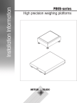
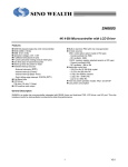
4.1 Setting up system modules
Hazardous area
GD13x
Power
supply
unit
Non-hazardous area
Weighing platform
K…x
D…x
GD15x
Interface
ID2sx/ID5sx
Weighing
terminal
Standard
configuration
Hazardous area
Non-hazardous area
ID5sx only
Maximum
expansion
6 outputs
3 inputs
• Set up weighing platform(s). See operating instructions of the weighing platform.
• Install a power supply unit for each weighing platform and fasten permanently in place using 4 screws (dimensions, see
section 5).
• Set up weighing terminal.
• Set up GD15x Interface(s) (if used) in the nonhazardous area. The GD15x has mounting holes for permanent screw
mounting if required (dimensions, see section 5).
4
4.2 Connecting devices
Attach devices in the following order:
1. Weighing platform to power supply unit
2. Weighing terminal to power supply unit
3. Interface to weighing terminal
4. Digital inputs/outputs at ID5sx
5. Equipotential bonding (see section 4.3)
6. Power supply (see section 4.4)
Preparatory work
While the devices are usually connected with the standard cables supplied, cables of lengths different to those of the
standard cables can also be used if they are prepared as described in section 4.6. This applies to the connections:
– from the weighing platform to the power supply unit,
– from the weighing terminal to the power supply unit,
– from the interface to the weighing terminal
– and from the weighing terminal to other intrinsically safe equipment via digital inputs/outputs.
General procedure when connecting devices
• Open device.
• Install prepared cable. To do this
– remove dummy stopper if fitted,
– ensure precise cable routing and correct seating of seals,
– tighten gland.
• Connect cable in device as described in the MMRx terminal diagram (see page 11 resp. page 12).
• Close device.
Connection of the weighing platform to the power supply unit
• To open the terminal box of the weighing platform, remove load plate if need be and replace after closing.
• In weighing platforms of type KC..., fix cable using cable ties to base frame so that it does not touch the moving lever
system.
• With K...x weighing platforms, following connection of the weighing platform to the power supply unit, secure by
breaking off the break-off screw at the terminal box of the weighing platform.
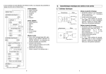
ME-42101839 supply converter
• With K...x weighing platforms equipped with the TBrickEx measuring cell the terminals of the supply converter
are not arranged in numeric order. It is essential to
comply with the modified order.
5 8 6 7 9 10
Connection of the ID5sx weighing terminal to the power supply unit
• On delivery, the ID5sx weighing terminal is preconfigured for one weighing platform. If necessary, set the hook switches
on the ID5sx board to match the number of installed weighing platforms (see service manual).
Connection of the interface to the weighing terminal
• Caution: The GD15x interface must be operated in the non-hazardous area.
• Route data line from non-hazardous area to hazardous area.
• Plug in power cable in non-hazardous area.
5
Connection of the digital inputs/outputs at ID5sx
Caution
Concept, assessment and installation of the equipment to the digital inputs/outputs are the sole responsibility of the end
user.
• Connect only intrinsically safe equipment.
• Check characteristics for intrinsic safety as prescribed in the declaration of conformity of ID5sx and the equipment to be
connected on the basis of the conditions described in section 4.5. Document your check of the characteristics.
• Prepare cable at weighing terminal end as described in section 4.6, at the peripheral end in accordance with the device
being attached. Ensure cable does not exceed maximum length.
• Connect cable at peripheral end as stipulated for the planned device. Ensure correct polarity.
Wiring of inputs
40x/1
40x/2
+
-
Wiring of outputs
40x/1
40x/2
+
-
4.3 Connecting equipotential bonding
Caution
The equipotential bonding must be installed by an electrician authorized by the end user. METTLER TOLEDO service
functions here only in a supervisory and advisory capacity.
• Connect equipotential bonding (EB) of all devices (ID2sx, ID5sx, GD13x, K...x or D...x weighing platforms, GD15x) in
accordance with the national regulations and standards. Ensure that
– all device housings are at the same potential by means of EB terminals,
– no compensating current flows via the shielding of the intrinsically safe cables.
4.4 Connecting power supply
Caution
The power supply must be connected only by an electrician authorized by the end user.
• Route power supply lead in accordance with the applicable national regulations and standards to GD13x power supply
unit (see GD13x model plate for voltage specifications).
• Pull cable through grounding cable gland into power supply unit and tighten gland.
• Attach connection leads in power supply unit as shown in MMRx terminal diagram (see page 11 resp. page 12).
• Close terminal box of GD13x power supply unit and tighten screws.
• Plug in power connector of GD15x interface (if used) in the non-hazardous area (see GD15x model plate for voltage
specifications).
4.5 Selecting peripheral units (ID5sx only)
Caution
For all characteristics of the peripheral unit mentioned in what follows, see approval documents of the peripheral unit.
4.5.1 Peripheral units for attachment to the outputs of ID5sx
Selecting peripheral unit
The following conditions must be met (see also MMRx terminal diagram on page 12):
1.
2.
3.
4.
5.
6.
6
U max (peripheral unit) £ U max (output), where U max (output) = 15 V
I max (peripheral unit) £ I max (output), where I max (output) = 40 mA
P max (peripheral unit) £ Pi max (output), where Pimax (output) = 150 mW
Ca (peripheral unit)
> Ci (output), where Ci (output) = 50 nF
La (peripheral unit)
> Li (output) where Li (output) = 0.5 mH
L (cable)/R (cable)
< La max (peripheral unit)/Ra (peripheral unit), where L (cable) is the length-related inductance
and R (cable) the length-related resistance of the cable to be used.
Calculating La max/Ra for the peripheral unit
With the protection-dependent energy characteristic e of the peripheral unit, the following results:
La max/Ra = 32/9 * e * Ri (peripheral unit)/U max
where e = 40 µJ for equipment with type of protection IIC.
Worked numeric example
Installation of the following equipment is envisaged:
• Isolation amplifier with NAMUR input following DIN 19234, type of protection EEx ib IIC T6 and the characteristics:
U max = 12.7 V; I max = 20 mA; P max = 63.5 mW; Ca = 1200 nF; La = 90 mH; Ri = 635 W
• Cable with the characteristics
L (cable) = 0.1 mH/100 m; R (cable) = 2.5 W/100 m
This results in
L (cable)/R (cable) = (0.1 mH/100 m)/(2.5 W/100 m) = 0.04 mH/W
La max/Ra = (32/9) * (40 * 10-6 J * 635 W)/12.7 V = 7.1 mH/W
The configuration meets all six conditions and is admissible at an ID5sx output.
4.5.2 Peripheral units for attachment to the inputs of ID5sx
Selecting peripheral unit
The following conditions must be met (see also MMRx terminal diagram on page 12):
1.
2.
3.
4.
5.
6.
U max (peripheral unit) = 15 V ... 30 V
I max (peripheral unit) = 15 mA ... 50 mA
P max (peripheral unit) = 56.25 ... 375 mW
Ca (peripheral unit)
> Ci (input), where Ci (input) = 50 nF
La (peripheral unit)
> Li (input) where Li (input) = 0.5 mH
L (cable)/R (cable)
< La max (peripheral unit)/Ra (peripheral unit), where L (cable) is the length-related inductance
and R (cable) the length-related resistance of the cable to be used. For the calculation of La max/Ra for the peripheral unit, see
section 4.5.1.
Worked numeric example
Installation of the following equipment is envisaged:
• Zener barrier with type of protection EEx ib IIC T6 and the following characteristics:
U max = 28 V; I max = 50 mA; P max = 350 mW; Ca = 60 nF; La = 12 mH; Ri = 620 W
• Cable (as above) with the characteristics
L (cable) = 0.1 mH/100 m; R (cable) = 2.5 W/100 m
This results in
L (cable)/R (cable) = 0.04 mH/W
La max/Ra = (32/9) * (40 * 10-6 J * 620 W)/28 V = 3.1 mH/W
The configuration meets all six conditions and is admissible at an ID5sx input.
7
4.6 Preparing cables
Customized cable
Max. length
Cable end length A
Power supply unit - weighing terminal
20 m
140 mm
480 mm
Power supply unit - weighing platform
20 m
120 mm
50 mm
100 m
80 mm
480 mm
Interface - weighing terminal
Peripheral unit (ID5sx)
- to inputs (I) weighing terminal
- to outputs (O) weighing terminal
Wire end ferrules with plastic collar,
crimp connection
Length A
depends on
peripheral
unit
15 m
15 m
480 mm
480 mm
Grounding cable gland
Fastening ring of
identcard
Cable (3 x 2 x 0.75 mm2) to
notional regulations for intrinsically
safe circuits
•
•
•
•
•
•
Cable end length B
Cable
shield
Length B
Push sleeve between
cores and shield
Cut cable to length: comply with max. admissible cable length in above table.
Strip insulation from cable ends in accordance with lengths A/B: comply with length to be stripped shown in above table.
Shorten shield to length 7 mm.
Strip insulation from litz wire ends.
Crimp wire end ferrules to litz wire ends with crimping tool.
Only with connection cables between weighing terminal and weighing platform:
Mount fastening ring of the identcard on the cable.
• Mount the three rear parts of the grounding cable gland on cable.
• Push sleeve between cores and shield.
Caution: Do not damage insulation of the cores!
• Mount front part of the gland and screw to the rear part.
8
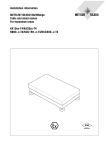
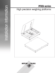
5. Installation dimensions of the system modules
Weighing terminals
- ID5sx bench version
25
185
5
50 90
265
194 (4xM4)
332
- ID5sx-E switch cabinet installation
- ID2sx bench version
9
Power supply unit
Interface
GD13x/EN version
GD15x
10
160
140
19
10
82
81
145
220
204
4 x Ø 6.2
4 x Ø8.8
8
284
140
2m
120
Weighing platforms
The installation dimensions of the weighing platforms can be found in the operating instructions of the weighing
platform in question.
10
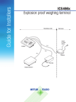
11
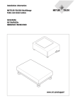
Caution
Power supply only via
GD13x; data
communication only
via GD15x
ID2sx Weighing
terminal
K15x, K32x:
T-Brick 15-Ex, T-Brick 32-Ex:
AWU…x:
terminals 5-10
terminals 5-10
terminals 5-8
Terminal box of the K15x, K32x,
T-Brick 15-Ex, T-Brick 32-Ex with
supply converter and AWU…x
measuring cells
Caution
T-Brick 15-Ex and T-Brick 32-Ex may
only be operated with the GD13x
power supply unit via the
ME-42101839 supply converter.
Replaces
Caution
Install GD 15x outside the
hazardous area
GD 15x
Interface
12
Caution
T-Brick 15-Ex and T-Brick 32-Ex may
only be operated with the GD13x
power supply unit via the
ME-42101839 supply converter.
00506467B
Subject to technical changes
© Mettler-Toledo (Albstadt) GmbH 02/11
Mettler-Toledo (Albstadt) GmbH
D-72458 Albstadt
Tel. ++49-7431-14 0, Fax ++49-7431-14 232
Internet: http://www.mt.com
Printed in Germany 00506467B