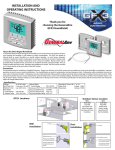
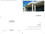
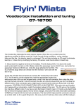
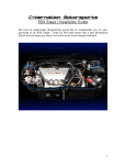
1
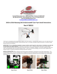
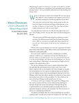
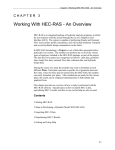
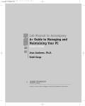
Granatelli Motor Sports, Inc. • 1000 Yarnell Place • Oxnard, CA 93033-2454
805-486-6644 (Phone) • 805-486-6684 (Fax) • Hours: M-F 8AM-5PM (PST)
www.GranatelliMotorSports.com/techsupport.htm [email protected]
Installation Instructions
2005-2007 Mustang GT
Single 76mm Turbo System
Proper Installation of the Granatelli Turbocharger Kit requires a general understanding of
automotive mechanics. Please read the entire installation manual completely and decided
whether you feel qualified to attempt the installation before you begin. A major portion of
this installation is to be done from the bottom. (4) Four sturdy jack stands with a minimum
of 18 inches of height is highly recommended.
Always use premium grade fuel 91 octane or higher and maintain regular oil changes every
3000 miles
Step (1) Find a place where you will be able to work on the car without having to move it
for at least 10 hours. Elevate car and place jack stands as wide as possible in all four
corners to support the car. A hoist is also very helpful.
Step (2) Disconnect (+) Positive and (-) Negative cables from battery using 5/16 or 8mm
wrench located at passenger side firewall
Step (3) Remove the entire factory air intake system. This includes the factory air box.
Note: Air Box is held in place by (2) 10mm bolts.
Step (4) Remove the plastic belly pan under the nose. Note: Held in place by (7) 5.5mm
screws. Keep this in a safe place as this part will be re-installed.
manual71.doc
© 2000-06 Granatelli Motor Sports, Inc. - All Rights Reserved - Intl. Copr. Secured –18Jul2006 V 1.0
1
Step (5) Remove plastic radiator cover. Note: Held in place by (6) push in clips.
Step (6) Remove front nose assembly held in place by 3 per side Phillips head screws at
lower front fender well. Note: It is also a good idea to remove the front tires to gain even
more access however, turning steering wheel lock to lock allows for all screws to be
removed. At front fender belt line, remove 1 per side 10mm bolts at the top of the engine
compartment, just to the side of each headlight. Before removing nose, disconnect wiring
harnesses to fog lights, turn signals and running lights.
Step (7)
Remove Passenger side headlight (3) 10mm bolts
Step (8) Remove windshield washer tank. (2) 10mm bolts and (1) 10mm nut off stud.
Note: this will be reinstalled.
Step (9)
Drain engine coolant. – Petcock is on passenger side bottom of radiator.
Step (10) Remove coolant tank (2) 8mm screws. Save to be reinstalled. Note: Once
bolts are removed, hold the tank up as high as possible so coolant in the tank drains back
to the engine, then pull 1” hose off bottom of the tank and drain excess coolant.
Step (11) Remove upper radiator hose off drivers’ side and at top of thermostat housing.
Disconnect lower radiator hose from drivers’ side of radiator.
Step (12) Remove bracket on block that supports radiator hose held in place by 15mm
nut on drivers side cylinder head. – This support bracket is not reused.
manual71.doc
© 2000-06 Granatelli Motor Sports, Inc. - All Rights Reserved - Intl. Copr. Secured –18Jul2006 V 1.0
2
Step (13) Remove (2) upper Radiator support bracket held in place by (2) 10mm bolts.
These parts are modified by drilling (2) 3/8 (7.93mm) holes in the brackets to pull the
upper portion of the radiator forward ¾ of an inch.
Step (14) Drill (2) two 3/8 holes, per bracket ¾” closer to the rubber grommet. Reinstall
brackets using newly drilled holes. We do this to tilt the top of the radiator/fan assembly
forward for more clearance for the turbo.
Step (15) Remove the power steering reservoir held in place with (1) 8mm bolt at fan
shroud. Drain all fluid.
Step (16) Remove factory power steering cooling tube. The tube is fastened in front of
the a/c condenser running from the rack and pinion and is returned back to the power
steering fluid reservoir. This is a simple “single pass” tube. It will no longer be needed.
Step (17) Remove the lower radiator hose.
Step (18) Remove the hose from the thermostat housing assembly to the expansion
reservoir.
Step (19) Remove the top/upper hose from the thermostat housing to the engine.
Step (20) Remove the side hose from the thermostat housing, leave the other end
attached to the engine.
Step (21) Remove the thermostat housing as an assembly to be modified
manual71.doc
© 2000-06 Granatelli Motor Sports, Inc. - All Rights Reserved - Intl. Copr. Secured –18Jul2006 V 1.0
3
Step (22) Remove the pressed in tube from the thermostat housing. This can be done 2
ways:
1. By heating the area around the pressed in fitting while moving it back and
forth, as the sealant get soft the fitting will pull out or
2. By placing the pressed in fitting in a vice and gently twisting it back and
forth. Once the pressed in fitting has been removed, clean out the excess
sealant and use a ½ npt tap to thread the hole. Once tapped and clean
apply thread sealer and install the supplied ½ npt x 5/8 barbed hose fitting.
Step (23) Remount the power steering reservoir to the left side strut tower using the
supplied bracket and hardware, use the existing tapped hole in the shock tower.
Step (24) Once the reservoir is mounted locate and install the 3/8 by 20” long, the hose
is routed from the reservoir to the rack and pinion. The larger of the two hoses needs to
be cut so you are able to rotate it to line up properly. Use the supplied ¾ brass hose
coupler and clamps.
manual71.doc
© 2000-06 Granatelli Motor Sports, Inc. - All Rights Reserved - Intl. Copr. Secured –18Jul2006 V 1.0
4
Step (25) Locate the lower radiator hose removed in step (17) cut and remove a 90
degree section from it.
Step (26) Install the 90 degree section of hose just modified onto the lower radiator outlet
pointing up at the 12 o’clock position.
Step (27) Install the thermostat housing modified in step (22) onto the lower radiator hose
as show in picture below.
Step (28) Install the aluminum extension pipe 1 ½ x 4” into the 1 ½ x 3” long silicone
hose, then install in between the radiator hose from the block. Tighten all clamps.
manual71.doc
© 2000-06 Granatelli Motor Sports, Inc. - All Rights Reserved - Intl. Copr. Secured –18Jul2006 V 1.0
5
Step (29) Lengthening the lower coolant Expansion Tank tube: Since we moved the
thermostat housing, now we need to extend the expansion tank hose that runs from the
thermostat housing to the tank. Locate ¾ x 5” metal extension tube supplied in your kit.
This needs to be installed in the middle of the lower reservoir hose to lengthen it. (See
photo). Once lengthened, reconnect to newly installed barbed fitting on housing
Fuel System Upgrades –
If you purchased a Granatelli Turbo kit that included injectors, now is the perfect time to
install them. Consult the factory service manual for detailed installation instructions.
However, this is really a simple and straight-forward procedure.
a. The fuel rails are held in place by two(2) 7mm bolts per side. Starting from
either side, remove the two bolts
b. Remove the wiring harnesses that snap into each injector
c. Wiggle the fuel rails in an upward motion. Doing so will gently pull the injectors
from their socket in the manifold.
d. Once the rails are away from the engine it will be easy to remove the factory
injectors and directly replace them with injectors supplied in the kit.
manual71.doc
© 2000-06 Granatelli Motor Sports, Inc. - All Rights Reserved - Intl. Copr. Secured –18Jul2006 V 1.0
6
Fuel Pump Upgrade
Your factory fuel pump is more then adequate to supply enough fuel to support 525 hp (at
the crank). When coupled with the Granatelli Turbo kit at less then 8psi, no fuel pump
modifications are required. Granatelli Motor Sports also offers a high flow / high pressure
fuel pump upgrade kit (part # GMFS0507) for those of you looking to exceed 480 rear
wheel hp. Caution internal engine modifications are highly recommended before
you proceed to increase boost past 10 psi.
Installing the Turbo Head Unit Mounting Brackets
Step (30) Your kit came with 5 spacers: 3 coupling nuts with 7/16 bolts and washers and
2 with 7/16 studs. The 2 shorts spacers with studs are used to mount the intercooler so
we are not ready for them. (see Intercooler Installation section) Locate the three coupling
nuts marked #1, #2, & #3. The #1 nut goes onto the lower alternator stud on the drivers’
side. #2 nut goes on the stud right under the water outlet neck on the driver’ side of
engine. Note: In some cases this stud will need to be shortened by cutting 3/8 of an inch
off the end of the stud. If required, simply remove the stud, make required modification
and reinstall bolt, now you can install #2 nut onto stud. #3 nut goes on the stud right
above power steering pulley. Note: this stud may require similar modifications as well.
Install #3 nut onto cut stud, tighten #1, #2, #3 nuts.
Step (31) Install the 2 turbo support backs, the straight bracket goes between #1 and #2
support Nuts first. (See photo).
manual71.doc
© 2000-06 Granatelli Motor Sports, Inc. - All Rights Reserved - Intl. Copr. Secured –18Jul2006 V 1.0
7
Step (32) The curved bracket goes between #2 and #3 nuts second.(See photo). These
brackets will go in several different ways, see photo to make sure they are installed
correctly. Note: The curved bracket stacks on top of the short bracket.
The last step is to install the oil drain tubing. The support bracket has the oil drain nipple
welded to it to prevent any chance for a leak. Put the oil drain hose on the bracket and
clamp tightly. Step 50 to 60 address getting the oil into the pan.
Installing Front Mount Intercooler
Step (33) The Intercooler is supported by the two(2) 8mm lower studs of the inter side of
the bumper mount. Start by threading the supplied intercooler spacers to the factory
studs. These are the spacers that have a ¼ x20 stud sticking out of one end. Once
spacers are fastened, mount intercooler and tighten in place using ½” wrench. When
facing the front of your car, the discharge side of intercooler should be pointing towards
passenger side of car on the bottom and the inlet side is pointing towards the drivers side
top Discharge side of intercooler is 3” and inlet side is 2.5” (See photo).
manual71.doc
© 2000-06 Granatelli Motor Sports, Inc. - All Rights Reserved - Intl. Copr. Secured –18Jul2006 V 1.0
8
Installing Discharge Tubing (3” Cold Side)
Your discharge tubing consists of 3 sections: MAF (mass airflow sensor) tube, transition
tube and throttle body tube. Additionally you were supplied a BA-2800 MAF and MAF
wiring harness extension.
Step (34) Install the blue GMS supplied blow off valve into the discharge transition tube
using the O-ring and snap ring supplied. Note: Vacuum nipple needs to point straight
down.
Step (35) A small portion of the passenger side head light support must be removed to
allow the discharge tubing to properly follow the path of least resistance. Using tin snips,
small air saw or narrow hacksaw cut the section out as needed (See photo).
Step (36) Install BA-2400 / BA-2800 MAF electronics into the appropriate section of
discharge piping. Be careful not to damage the electronics as you insert them into the
tube.
manual71.doc
© 2000-06 Granatelli Motor Sports, Inc. - All Rights Reserved - Intl. Copr. Secured –18Jul2006 V 1.0
9
Note the “airflow” arrow on the electronics and confirm the arrow points in the path of the
throttle body and not towards the intercooler. (see photo below step 39)
Step (37) With the MAF electronic securely fastened into the tube, connect the MAF tube
to the intercooler using the supplied 3” to 4” adapter sleeve with #64 clamp.
Step (38) Using the 3” x 4” long coupler sleeve, attach the transition elbow with #44
clamps.
Step (39) Using the 3” x 45^ angle coupler sleeve, install the throttle body tube in at one
side and using the 6” x 4” long coupler sleeve in the oval configuration fasten to the
throttle body. (See photo).
Step (40) Locate supplied MAF extension harness and install from factory wire to new
MAF sensor.
Step (41) Reinstall the windshield washer fluid tank back to the factory position and
location.
Step (42) Remove catalytic converter “H” pipe (“Y” in shape) section from exhaust
manifolds and save nuts and band clamps.
Step (43) Measure 2” in front of hanger brackets and cut both pipes. (See photo).
manual71.doc
© 2000-06 Granatelli Motor Sports, Inc. - All Rights Reserved - Intl. Copr. Secured –18Jul2006 V 1.0
10
Step (44) The starter wires will need to be rotated up to clear the new exhaust pipes.
Simply loosen wires to starter and flip them 180^ so that they are facing up. (See photo).
Before
After
Before
After
Sway Bar Drop Brackets. In order to add clearance for the down pipe from the
turbo the sway bar must be dropped one bolt hole. The sway bar will have to be relocated
by dropping it down 3 inches.
Step (45) Remove the (4) 15mm sway bar mounting nuts holding the sway bar to the
radiator omega brackets and remove sway bar from the studs. You will need to cut 3/8 of
an inch off the top of the studs.
Step (46) Locate the sway bar relocation brackets and (2) 3/8 x 1 bolts, locknuts and
washers. These brackets relocate the sway bar 3” lower. Install slotted sway bar drop
brackets over factory studs protruding from Omega brackets. The top factory sway bar
retainer hole now mounts the supplied brackets and the bottom stud from the factory
omega bracket now becomes the top-mounting hole for the sway bar clamps
Step (47) Reinstall sway bar onto brackets. (See photo).
manual71.doc
© 2000-06 Granatelli Motor Sports, Inc. - All Rights Reserved - Intl. Copr. Secured –18Jul2006 V 1.0
11
Step (48) Drain Engine Oil
Step (49) Locate 23 ½” oil pressure hose ¼ tee and ¼ x -3 90˚.
Step (50) Remove oil pressure sending unit from oil filter adapter and install ¼ pipe tee
and ¼ x -3 90˚ fitting, see photo for clocking. Install –3 braided steel oil feed hose and
tighten, reinstall sending unit.
Step (51) Locate 3/8 oil drain tee and 3/8 x ¾ hose barb,
Step (52) Remove oil level sensor on passenger side of oil pan.
manual71.doc
© 2000-06 Granatelli Motor Sports, Inc. - All Rights Reserved - Intl. Copr. Secured –18Jul2006 V 1.0
12
Step (53) Install 3/8 tee and hose barb and reinstall oil level sensor, see photo for
clocking.
Step (54) There are some power steering tubes that will need to be bent to clear the
exhaust discharge pipe, see photo to see which way they need to be bent , be careful not
to kink or break them.
Installing Turbocharger Head Unit
Step (55) Locate turbocharger, oil drain gasket and two 8mm oil drain bolts. Using
gasket sealer, glue gasket on to support bracket. Do not use silicone. Install
turbocharger onto support bracket using the two 8mm bolts and finger tighten only.
manual71.doc
© 2000-06 Granatelli Motor Sports, Inc. - All Rights Reserved - Intl. Copr. Secured –18Jul2006 V 1.0
13
Step (56) Locate all exhaust pipes and two rolls of heat wrap, you will need to heat wrap
all exhaust pipes except the 3” Y pipe and the two converters. (See photo).
Step (57) The crossover pipe is next, we have pre assembled this pipe, it will go in
assembled, install it now, leave the bolts loose for positioning.
Step (58) Locate small support bracket. This bracket bolts to the 2 ½ pipe and to the
lower front A/C stud (See photo), leave loose for positioning.
manual71.doc
© 2000-06 Granatelli Motor Sports, Inc. - All Rights Reserved - Intl. Copr. Secured –18Jul2006 V 1.0
14
Step (59) Install exhaust turbine drive pipe. Four bolt square flange on turbine side and
V band flange on the other side. This pipe goes from the turbo inlet to the 2 ½ pipe
installed above. Locate 2 ½ V band clamp, turbo inlet gasket and four 3/8 x 1 ¼ bolts and
locknuts. Install pipe onto bottom of turbo using gasket bolts, nuts and V band clamp. Do
not tighten yet.
Step (60) Locate four(4) 3/8 x 1” exhaust discharge bolts. Install the first bolt into the
upper rear exhaust turbine house through the support bracket. Finger Tight.
Step (61) (Locate exhaust discharge pipe, install this pipe onto turbo and under oil
filter, using the four 3/8 x 1” bolts and gaskets, do not tighten. (See photo).
Step (62) Once all these pipes have been installed, position pipes for clearance from
frame, radiator fan, AC compressor, sway bars mounts, tighten all bolts on turbo mount
from steps 55 to 62. Double check for clearance.
Step (63) Attach oil feed hose to turbo and tighten.
manual71.doc
© 2000-06 Granatelli Motor Sports, Inc. - All Rights Reserved - Intl. Copr. Secured –18Jul2006 V 1.0
15
Step (64) Install heat shield on turbo.
Step (65) Locate exhaust pipe and V band clamp, this pipe has a V band inlet and a 3”
slip outlet. Install onto down pipe using the V band clamp. This pipe should be pointed
straight back. Do not tighten yet.
Step (66) Locate Y pipe and two 3” V band clamps. Install Y pipe next.
Step (67) Locate converters and install onto previous mounted exhaust piping. (See
photos).
Step (68) Install V band clamps, position all pipes as to clear frame, power steering,
hoses, and floorboard, tighten all clamps now from steps 63 to 68. Double check for
clearance.
Step (69) Install three O2 sensors, one in crossover and one in each converter
Step (70) Reinstall previously cut factory rear H pipe. (“Y” in shape)
manual71.doc
© 2000-06 Granatelli Motor Sports, Inc. - All Rights Reserved - Intl. Copr. Secured –18Jul2006 V 1.0
16
Step (71) Locate wastegate and wastegate pipe, install wastegate now using supplied V
band clamps. Install wastegate discharge pipe, position pipe to clear sway bar and oil filter
and steering rack, tighten both clamps. Install wastegate pressure hose from turbo
compressor outlet to the side of wastegate. Your kit came preset at 7lbs of boost which
will support 450 hp and 470 ft/lbs of torque to the rear wheels Do not use top wastegate
port unless you are using a boost controller not supplied.
Installing Discharge Tubing (2 1/2” Hot Side)
Step (72) Install 90^ 2 ½” elbow on to driver side of intercooler with 90^ elbow facing
straight down. The first pipe goes between radiator fan and frame
Step (73) Install couplers onto turbo discharge and then slide pipe in from bottom and
into the coupler on turbo
Step (74) The second pipe, the horseshoe shaped intercooler inlet tube, goes from
intercooler to first pipe, (see photo)
manual71.doc
© 2000-06 Granatelli Motor Sports, Inc. - All Rights Reserved - Intl. Copr. Secured –18Jul2006 V 1.0
17
Once both pipes are installed, tighten all clamps making sure pipes do not come in
contact with brake lines or A/C hoses.
Step (75) Locate oil drain hose and two #10 clamps. Install onto turbo drain and oil pan.
Be sure to make sure hose does not come in contact with any moving parts or exhaust
pipes.
Step (76) Locate air filter, 4” coupler, two(2) #64 clamps, and air filter pipe. Install
coupler onto turbo. Install air filter onto pipe and install onto turbo. Position filter so it has
clearance and tighten.
manual71.doc
© 2000-06 Granatelli Motor Sports, Inc. - All Rights Reserved - Intl. Copr. Secured –18Jul2006 V 1.0
18
Step (77) Locate stainless water pipe and two 1-¼ couplers and four #24 clamps.
Install couplers onto motor and thermostat. Install pipe, be sure pipe clears brake lines
and turbo housing. (See photo).
Step (78) The breather system needs to be modified, the1/2 hose that goes from drivers
side valve cover needs to be cut and check valve needs to be installed. Remove tube
from engine and cut 1 ¾ section out of straight section, install check valve with arrow
pointing towards engine and tighten clamps, reinstall now. (See photo).
Step (79) The crank case vent needs to be modified also, this tube is on the passenger
side valve cover, remove tube and strip plastic tube off of valve cover fitting, locate 3/8
breather hose and install from passenger side valve cover to air filter pipe.
manual71.doc
© 2000-06 Granatelli Motor Sports, Inc. - All Rights Reserved - Intl. Copr. Secured –18Jul2006 V 1.0
19
Step (80) The plastic radiator cover needs to be notched to clear bypass pipe. (See
photo).
Step (81) Lower plastic air deflector, needs to be modified, (see photo) reinstall washer
reservoir , fill cooling system , install oil, fill power steering reservoir, install injectors, and
hook battery up.
Completed Kit
manual71.doc
© 2000-06 Granatelli Motor Sports, Inc. - All Rights Reserved - Intl. Copr. Secured –18Jul2006 V 1.0
20
LIMITED WARRANTY:
Granatelli Motor Sports warrants that all products shall be free from defects in materials and/or workmanship for ninety days from the
date of purchase (except in-tank and in-line fuel pumps purchased at dealer or wd prices as these items have no warranty and roller
rocker arms which have a 12-month limited warranty). The following requirements and exclusions apply: (1) You must be the original
purchaser and must complete the warranty registration form (located at www.GranatelliMotorSports.com/warranty.asp) and return the
defective product within 10 days after the expiration of the product warranty. Failure to do so voids all warranty, either express or
implied set forth herein. (2) You must reside in the United States or Canada and use the product as described in the warranty
registration. (3) The product must not have been altered, disassembled, modified, or converted for any other use than intended by
Granatelli Motor Sports. (4) The product, or any part thereof, is not used in accordance with the operating parameters specified by
Granatelli Motor Sports (5) The product or any part thereof is damaged or rendered unserviceable due to negligence, vandalism, theft,
fire, debris, flood, Act of God, or other peril, malfunction of equipment, or by any cause within the Customer's control. (6) The serial
number (if applicable) must not have been altered or removed. The extent of Granatelli Motor Sports' liability under this warranty shall
be limited to the prompt correction or replacement, at Granatelli Motor Sports' option and at no cost to the customer other than return
shipment, of any defective part of the product determined to be necessary by Granatelli Motor Sports. This only applies if written
Granatelli Motor Sports received notice of the claimed defect prior to expiration of the warranty period. All warranties of merchantability
and fitness for a particular purpose are expressly excluded. The duration of any and all implied warranties is limited to the duration of
this express warranty. All incidental and consequential damages including but not limited to loss profits even if it has been advised of
the possibility of such damages are hereby excluded. Regardless of the form of the claim, Granatelli Motor Sports liability for any
damages to the customer for such product is limited to the guidelines herein. This stated, expressed warranty is in lieu of all liabilities or
obligations of Granatelli Motor Sports for damages arising out of or in connection with delivery, use or performance of the product. This
warranty cannot be amended or changed by any Granatelli Motor Sports representative, employee, or agent and any promises
inconsistent with this warranty are void and unenforceable against Granatelli Motor Sports. Some states do not allow limitations of
incidental or consequential damages, so the above limitations or exclusions may not apply to you. This warranty gives you specific legal
rights and you may have other rights that vary from state to state. Your sole remedy for the above warranties is the repair or
replacement of the defective product only, at Granatelli Motor Sports' sole discretion.
RETURN POLICY:
Before you return a product for a warranty claim, contact our service department M-F 8AM-5PM (PST) at 805-486-6644 or
[email protected] for an RGA number. No returns are accepted without a pre-approved RGA (return goods
authorization). No returns on special orders, electrical items or after 90 days from date of original shipment. All returns must be safety
packaged in original packaging (if available) and clearly marked with your RGA number on the top and two sides of the box. Please
insure your shipment for full replacement value as lost, stolen or items damaged in shipment are not covered by our limited warranty.
We recommend using FedEx (www.FedEx.com) or UPS (www.UPS.com) for shipping. Lost, stolen or damaged items claims must be
made by the customer and resolved by the freight company and not Granatelli Motor Sports. All returns may be subject to a restocking
fee of up to 25%. The balance will be returned in the form of a company check or may be applied as credit towards another purchase.
PERFORMANCE CONSUMER'S BILL OF RIGHTS:
Legally, a vehicle manufacturer cannot void the warranty on a vehicle due to an aftermarket part unless they can prove that the
aftermarket part caused or contributed to the failure in the vehicle (per the Magnuson Moss Warranty Act,
www.GranatelliMotorSports.com/magnusonmoss.htm (15 U.S.C. 2302(C)). For best results, consider working with performanceoriented dealerships with a proven history of working with customers. If your vehicle manufacturer fails to honor emission/warranty
claims, contact EPA at (202) 260-2080 or www.epa.gov. If federal warranty protection is denied, contact the FTC at (202) 326-3128 or
www.ftc.gov. For additional information, check out www.GranatelliMotorSports.com/TechSupport.htm.
Disclaimer:
Actual products may vary from photographs shown. For latest information, please call 805-486-6644 first. You can also check out our
web site at www.GranatelliMotorSports.com. However, it may have not been updated at the time you actually view it. Therefore, we
cannot guarantee the accuracy of the information on our web site. Granatelli Motor Sports is not responsible for any unintentional
omissions or typographical errors and reserves the right to make changes to packages, services, operating procedures, colors,
materials, features, specifications, part numbers, pricing and to discontinue any products and/or components at any time without prior
notice. Some items shown are sold for off-road use only and/or racing use (not street legal) and not intended for use on public
highways, customer assumes costs and liability for installation and use. Performance figures shown can vary considerably due to a
variety of factors including but not limited to altitude, humidity, barometric pressure, outside temperature, vehicle age, state of vehicle
tune, vehicle manufacturer engine tolerances, vehicle modifications, chassis and engine dyno calibration, chassis and engine dyno
brand, etc.
manual71.doc
© 2000-06 Granatelli Motor Sports, Inc. - All Rights Reserved - Intl. Copr. Secured –18Jul2006 V 1.0
21