1
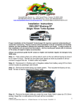
RSX Stage I Installation Guide
We here at Cybernation Motorsports would like to congratulate you on your
purchase of our RSX Stage I Turbo Kit. We have spent over a year developing
this kit and we hope you enjoy it as much as we have enjoyed making it.
1
This manual was designed as a guide for mechanics to install this kit. This is a
Level 10 installation that requires special tools and a good understanding of
automotive knowledge. Cybernation Motorsports takes no responsibility for any
problems or damaged that may or may not have been caused by errors in this
manual or errors done during installation. The Cybernation RSX Stage I Kit is a
High Performance aftermarket upgrade and is for off road use only. This turbo kit
like all others is not emissions legal. Installation is done at the users own risk.
Before starting the installation please go to www.cybernationmotorsports.com for
possible updates to this manual.
2
Parts List (for K20A2 / K20A3)
QTY….. PRODUCT DESCRIPTION
1 ….. Cybernation Customized Turbo
1….. Intercooler
1….. Set of Intercooler Piping (2 U-Bends / 1 J-Bend / 3 Long)
1….. Intake Filter
4 ….. Cybernation 550cc Injectors
4 ….. Injector Clips w/ 8 plug contacts
1 ….. BOV (blow off valve)
********************************************************
Note: The BOV Brand may vary due to availability and customer preference
********************************************************
1….. 3” Down Pipe
1….. Dump Pipe
1….. Turbo Manifold
1….. Exhaust Manifold
1….. Waste Gate
********************************************************
Note: The Waste Gate Brand may vary due to availability and customer preference
********************************************************
1….. Air/Fuel Gauge
1….. Boost Gauge
7….. 4 Layer Thermal Flex Couplers
1….. Throttle Body Hose (silicon transition)
1….. Cobra Fitting (90 Degree)
1….. Set of Vacuum Lines
1….. #4 Oil Feed Line 12”
1….. 1/8 Female Tee
1…..#10 Oil Return Line
1….. Oil Return Flange
14… Hose Clamps 036
3….. Large Clamps 56
1….. #10 Bulkhead Nut
1….. #10 Hose Fitting (male)
1….. #10 Hose Fitting (female)
1….. 1/8 Nipple Flare
1….. Rubber Grommet
11… Turbo Bolts
2….. Fuel Rail Bolts & Washers
1….. Wiring Diagram
3
Tools and Equipment List
************************************************************************
NOTE: All tools listed are what Cybernation Motorsports uses during installations. Some tools may or may not be
substituted. Some tools such as socket types are specific and required for the installation and will be labeled
accordingly.
Screw Drivers
Assorted Regular
Assorted Phillips
________________________________________________________________________
Pry Bar (optional but makes life easier)
1’
2’
3’
________________________________________________________________________
Hammer
Steel
Rubber or Plastic
________________________________________________________________________
Ratchet Set
¼”
½”
________________________________________________________________________
Ratchet Extensions
3”
6”
24” (recommended)
________________________________________________________________________
4
Sockets
Metric
8mm (shallow or deep throat socket ok)
10mm (deep throat socket REQUIRED)
12mm (deep throat socket REQUIRED)
14mm (shallow or deep throat socket ok)
16mm (deep throat socket REQUIRED)
17mm (deep throat socket REQUIRED)
18mm (deep throat socket REQUIRED)
19mm (deep throat socket REQUIRED)
21mm (deep throat socket REQUIRED)
23mm (deep throat socket REQUIRED)
Standard
9/16”
¼”
7/16”
½”
¾”
________________________________________________________________________
Wrenches
Metric (NOTE : all wrenches listed should be open and closed ended)
10mm (6 or 12 point ok)
12mm (6 or 12 point ok)
14mm (6 point REQUIRED)
Standard
9/16”
¼”
7/16”
½”
¾”
________________________________________________________________________
Car Jack and Jack Stands
________________________________________________________________________
Drill
¼”
½”
________________________________________________________________________
Drill Bits
7/8 step up bit (Substitute 7/8” metal drill bit)
________________________________________________________________________
Needle Nose Pliers
________________________________________________________________________
Channel Locks
________________________________________________________________________
Wire Cutters
________________________________________________________________________
Crimpers
________________________________________________________________________
Wire Strippers
________________________________________________________________________
5
Soldering Iron
________________________________________________________________________
Heat Shrink (Substitute : Electrical Tape)
________________________________________________________________________
Tie Straps
Small
Medium
Large
________________________________________________________________________
Torque Wrench (recommended in conjunction with Service Manual)
________________________________________________________________________
2 Adjustable Wrenches
________________________________________________________________________
Stud Puller (optional)
________________________________________________________________________
Oil Pan Seal Cutter (optional)
________________________________________________________________________
Honda Bond (Substitute : Permatex Ultra Gray)
________________________________________________________________________
Brake Cleaner. (this stuff goes quick so make sure to get a few cans)
________________________________________________________________________
6
Additional Recommended Tools and Equipment
The rest of this list includes tools that make the installation easier but are not required.
Car Lift
________________________________________________________________________
Acura RSX Shop Manual (Once can be obtained from helminc.com)
________________________________________________________________________
Digital Multi Meter (sub 200ohm)
________________________________________________________________________
Air Tools
Impact Gun
Grinder
Air Ratchet
________________________________________________________________________
Bench Grinder (w/ stone and wire wheel)
________________________________________________________________________
Digital Torque Wrench
________________________________________________________________________
Parts Cleaner
________________________________________________________________________
Drill Press
________________________________________________________________________
Quarter Panel Blanket or Cover (to prevent scratches)
7
Installation Guide
1. Disconnect the battery when performing this installation.
2. Remove the Front Bumper.
3. Put the car on an auto lift. If one is not available then use a jack and jack stands. If
using jack stands use extreme caution and make sure that they are secure.
4. Drain the oil from the car.
5. Before removing the sub-frame you must remember to make note of the subframe alignment markers. There is one marker indicated by 3 lines by the rear
sub-frame bolts. Make a note of these in relation to the bolts to ensure that the reinstallation of the sub-frame is straight. To remove the sub-frame, removing the 4
bolts that hold it, as well as the motor mount bolts in the front and the rear. (Note:
some cars have it in front of the rear sub-frame bolt.)
6. Remove the oil pan. WARNING!!!!!! DO NOT HAMMER A SCREW DRIVER
IN BETWEEN THE OIL PAN AND JOURNAL TO REMOVE IT! Damage to
the oil pan and or journal itself could cause oil leaks when put back together.
There are pry points you must use to remove the oil pan.
7. Once the oil pan has been removed, clean off the old Honda Bond being careful
not to gouge the pan. Do the same with the journal.
8
Manual Update Notice
If your kit came with a steel braided oil return line and
anodized fittings, do not drill the 7/8” hole in the oil pan as
described in the next section. The bulk head for the new oil
return line assembly should be ¾”.
9
8. Drill a hole using a 7/8” step-up drill bit in location shown in Figure 1. It is
important that the oil return line is not drilled low. If so, the oil may not flow
properly and the turbo could be damaged.
Figure 1
10
9. After drilling the hole, insert the bulkhead (seen in figure 2) in the hole drilled in
the previous step with the longer end on the inside of the pan. Screw the nut and
the washers hand tight. Make a mark on the bolt about 1/8” after the nut. Once the
bolt has been marked remove the bolt and cut it along the mark that you have
made. Now that the bolt has been cut, re-insert the bolt and washers and nut. You
will need to apply Honda Bond (if Honda Bond is not available “Permatex Ultra
Grey” can be substituted) between each plastic washer and the oil pan as well as
the nut on the inside of the oil pan. Tighten using 2 adjustable wrenches. It is
recommended to wait until the turbo and manifold and sub-frame are reinstalled
before attaching the #10 female push lock fitting for the oil return line. When
installing the #10 female push lock fitting use Honda Bond. Make sure not to get
any Honda Bond in the oil passage. If the Oil Passage is block it will prevent oil
flowing back into the oil pan, which will damage the turbo. (Note: Read
directions on sealant for curing times)
Figure 2
11
10. Before reinstalling the oil pan, make sure to thoroughly clean any excess oil that
may have accumulated on the journal with brake cleaner. Any oil not cleaned off
could cause the adhesive to not bond properly together, which will cause oil to
leak. Apply Honda Bond to the oil pan and reinstall. When reinstalling the oil pan
make sure not to get Honda Bond on the oil pump. NOTE: If the Honda Bond
applied to the oil pan has been sitting for more than 5 minutes, do not install the
oil pan. Remove the Honda Bond thoroughly and reapply.
11. Remove the O2 Sensors from the exhaust then remove the stock exhaust.
WARNING: Take care not to damage the exhaust gaskets when removing the
stock exhaust system from the motor. You will reuse it for the installation. Once
the exhaust system has been removed, inspect the gaskets for any sign of wear
such as scaring, tearing or deformity. If any of these are seen in the inspection,
replace with a new one. (Note: When removing the exhaust from the motor, it is highly
recommended that you use a 6 point closed ended wrench to prevent stripping of the nuts
and bolts)
12. Now that the exhaust is out of the way, remove the Oil Pressure Sensor. Replace with the
1/8” nipple and Brass T. When installing brass T and the 1/8” nipple to the motor do not
be alarmed if the nipple does not screw in very far before beginning to get tight. This is
normal. Reconnect the oil sensor to the brass T. This will leave one hole available on the
bottom for the Oil Feed Line, which we will get to later. (Note: Use Honda Bond when
connecting the Brass T to the motor as well as the Oil Pressure Sensor and 1/8” nipples. Ensure
that no adhesive is put into the oil passageways .Any clogs can and will cause insufficient oil
pressure to reach the sensor and the turbo. If this happens, the turbo will fail from oil starvation.)
13. Loosen (but do not remove) the bolts on the turbo shown in figure 3.
Figure 3
12
14. After the Bolts have been loosened, connect the turbo to the turbo manifold using
the provided hardware (metal gasket and nuts) but do not tighten fully until the
turbo has been rotated. Now that the turbo is connected (loosely) to the turbo
manifold, turn the turbo so that the position matches figure 4. The turbo should be
roughly 1-½” to 2” from the exhaust. Once the turbo has been properly clocked,
tighten the bolts mentioned in figure 3 as well as the turbo and turbo exhaust nuts.
Make sure that the bolts that connect the turbo and the manifold are very tight.
**Tech Tip** It is recommended that you install the Thermal Flex coupler to the
turbo before mounting it to the motor. It is much easier to tighten when it is out of
the car. Then install the 90 degree push lock vacuum fitting using Teflon tape in
the hole indicated in Figure 4 by the red arrow and install the nylon vacuum line.
Figure 4
13
15. Connect the turbo to the Down Pipe. Also make sure that you connect the Oil
Feed Line using a 1/8” nipple flare and Oil Return Flange and male Oil Return
Fitting before you install the assembly to the motor. (depending on the kit, some
oil return flanges will come with a gasket. If your kit did come with a gasket, do
not use it. Instead use Honda Bond for sealing. The oil feed line uses a
compression fitting. No Honda Bond or Teflon tape is required). You should now
have what looks like in figure 5.
Figure 5
16. With the turbo, manifold and down pipe assembled, bolt it up to the motor. After
installing the turbo reconnect the rear exhaust system along with the stock gaskets
and reinstall the O2 sensors. (Note: When installing the turbo manifold to the car, you
should use a #14mm 6 point closed ended wrench to prevent stripping of the nuts and bolts. These
bolts must be very tight to prevent them from coming loose. Also, do not forget to install the
exhaust gasket. If the current one is damaged then it must be replaced with a new one)
17. Connect the Oil Feed Line to the available hole on the Brass T using a 1/8” nipple flare.
18. Connect the Female #10 Push-Lock fitting to the #10 Bulkhead and connect the
Oil Return Line from the turbo to the oil pan.
19. Reinstall the Sub-Frame using the reference points made before removal.
14
20. Install the cobra fitting (figure 6) onto the turbo.
Figure 6
**Tech Tip** Installation of the
cobra should be installed after the
turbo and manifold have been
installed. Failure to do so will make
installation of the turbo and
manifold more difficult.
21. Install the waste gate and down pipe to the now mounted turbo manifold. **Tech Tip**
DO NOT install the waste gate and dump pipe before the turbo and manifold have been
bolted up. Installation before this will make the installation of the turbo and manifold
much more difficult.
22. Install Dump Pipe to the Waste Gate.
23. Attach the Waste Gate to the turbo manifold.
24. Install a 90-degree push-lock vacuum fitting to the side of the Waste Gate. If your kit
came with the Evolution waste gate you will notice 2 ports on the side where the fitting
can be installed. Use the bottom one.
25. Attach the vacuum line you installed onto the turbo to the 90-degree push-lock vacuum
fitting you just installed. (WARNING!!!! THIS IS A CRITICAL PART OF THE
INSTALLATION. FAILURE TO INSTALL THIS VACUUM LINE WILL
RESULT IN OVERBOOST, WHICH CAN AND WILL CAUSE THE ENGINE TO
FAIL. WITHOUT THIS VACUUM LINE THE WASTE GATE WILL NOT
WORK AND THE CAR WILL BOOST AS MUCH AS THE SYSTEM CAN PUSH
WHICH IS 30lbs T0 40lbs MAKE SURE THAT THE VACUUM LINE IS NOT TO
CLOSE OR TOUCHING THE TURBO MANIFOLD AND IS FREE OF
OBSTRUCTIONS. )
15
26. Injector installation.
a.) Remove both motor covers from the valve cover and intake manifold to allow
access to the injectors and fuel rail.
b.) Remove the stock injector clips.
c.) Remove the fuel rail.
d.) Save the stock spacers, as you will use them during the reinstallation of the fuel
rail.
e.) Remove the fuel rail studs with a stud puller.
f.) Remove the stock injectors. Make sure that none of the stock o-rings are still in
the injector cradles as well as in the fuel rail.
g.) Each injector clip has a wire approximately 2” long going back to the harness
wrapped in black rubber. Either cut or push back the rubber as far as possible to
the harness.
h.) Cut the old injector clips. Try to cut as close to the plug as possible. This will
save you the work of crimping on extension for the new plugs.
i.) Strip the ends of the wires about 3/10”.
j.) Feed the wires through the new injector clip. Make sure to keep the same color
wires on the same sides as the original injector plugs. The Yellow and Black wire
should be installed on the right side of the clip. To determine the right side, look
at the injector clip with the female connection side face down and the release clip
at the top. Note: The new metal contacts have to be crimped on with the wires
through the plugs since they clip in backwards.
k.) Crimp the new connectors to the stripped wire. Then pull the wires back through
the clip. (Note: The new connectors have a longer piece of metal on one side than
the other. This side will go to the slit on the injector clip. If it is not pulled
through with them aligned it may damage the connector and prevent the
connector from locking in place.)
l.) Attach the new injectors to the fuel rail. The injector clip connectors on the new
550cc injectors should be facing toward the rear of the car.
m.) Reinstall the fuel rail and new injectors using the stock spacers and washers and
bolts provided with the kit. You must make sure that the fuel rail is flush and
level to prevent leaks. Most installations require about 6 washers per side along
with the stock spacers. **Tech Tip** Make sure that you reconnect the ground
wire for the fuel rail. This is a commonly missed step. This will save you a lot of
trouble shooting later on.
n.) Attach the new injector clips to the 550cc injector plugs.
16
27. Intercooler piping installation overview. Refer to Figure 22 for routing information.
28. Please note: The u-bends that come with the kit have extra length on them to
accommodate aftermarket setups. Depending on whether or not you have a stock or
aftermarket bumper you may or may not have to cut the u-bends for proper fitment.
29. We have designed our kit so that the front bumper support does not have to be removed.
For installation, center the intercooler under the bumper support rail with the tabs facing
up. The intercooler should be installed as far back as possible with out touching. Mark
the tabs that are welded onto the intercooler, then drill and secure them to the bumper
support.
Figure 22
17
Page Intentionally Left Blank
18
This section covers the wiring of the system. WARNING!!! WHEN PERFORMING THIS
SECTION OF THE INSTALLATION, MAKE SURE THAT THE BATTERY IS
DISCONNECTED.
30. Remove the access panel on the side of the dash as indicated in figure 14
Figure 14
19
31. Remove the access panel from under the steering wheel on the inside of the car.
32. Remove the access panel from under the Glove Box.
33. Note: If installing a gauge pod, insert the wiring for the boost gauge and air/fuel gauge
before feeding down through the dash. Run all leads (power wires and pressure line for
the boost gauge) for the gauges from top of the dash as indicated in Figure 14. With the
side access panel removed feeding the wiring down through the dash is easier.
WARNING!!! TAKE CARE NOT TO KINK THE PRESSURE LINE FOR THE
BOOST GUAGE.
34. Run the Boost Gauge pressure line from inside the car out to the engine bay and
connect to a vacuum source. The u shaped vacuum line in front of the valve cover
will work fine.
35. Connect the power and ground for the Boost Gauge to the location shown in the diagram
below.
20
Guardian E.I. Installation
Note!!!
Disconnect battery when
installing the Guardian Unit.
21
22
23
24
25
26
27
28
29
30
31
Air Fuel Gauge Wiring Instructions
These instructions are intended for the Autometer Ultra Light Gauges only.
1.) Tap A/F Gauge RED wire to Guardian YELLOW wire.
2.) Tap A/F Gauge BLACK wire to Guardian PINK wire.
3.) Tap A/F Gauge PURPLE wire to Guardian WHITE with RED stripe wire.
32
Congratulations! You have finished the installation.
IMPORTANT! PLEASE READ.
Before test driving your car, ensure that all nuts and bolts are secure. Also to make sure that you
add oil back to your car. Check for fuel leaks and oil leaks before driving the car.
When driving your car for the first time, pay attention to the Air/Fuel and Boost Gauges. Drive
your car at a slow pace, check to make sure that the boost is not exceeding more then the
recommended psi for your stage kit. For stage 1 you want to be at around 7 to 8psi of boost. Also
make note of the Air/Fuel gauge. Make sure that the gauge stays in the green under acceleration.
You can progressively drive the car faster as you ensure everything is ok.
Stop boosting the car immediately if Air Fuel gauge does not read green while at wide-openthrottle and call Cybernation for help.
33