1
Change for Life
Service Manual
02'(/ *:+0%$'1$&
*:+0%$'1$&
5HIULJHUDQW5$
GREE ELECTRIC APPLIANCES,INC.OF ZHUHAI
6HUYLFH0DQXDO
7DEOHRI&RQWHQWV
3DUWĖ 7HFKQLFDO,QIRUPDWLRQ
6XPPDU\
6SHFL¿FDWLRQV
6SHFL¿FDWLRQ6KHHW
2SHUDWLRQ&KDUDFWHULVWLF&XUYH
&DSDFLW\9DULDWLRQ5DWLR$FFRUGLQJWR7HPSHUDWXUH
&RROLQJDQG+HDWLQJ'DWD6KHHWLQ5DWHG)UHTXHQF\
1RLVH&XUYH
2XWOLQH'LPHQVLRQ'LDJUDP
,QGRRU8QLW
2XWGRRU8QLW
5HIULJHUDQW6\VWHP'LDJUDP
(OHFWULFDO3DUW
:LULQJ'LDJUDP
3&%3ULQWHG'LDJUDP
)XQFWLRQDQG&RQWURO
5HPRWH&RQWUROOHU,QWURGXFWLRQ
%ULHI'HVFULSWLRQRI0RGHVDQG)XQFWLRQV
3DUWė ,QVWDOODWLRQDQG0DLQWHQDQFH
1RWHVIRU,QVWDOODWLRQDQG0DLQWHQDQFH
,QVWDOODWLRQ
,QVWDOODWLRQ'LPHQVLRQ'LDJUDP
,QVWDOODWLRQ3DUWVFKHFNLQJ
6HOHFWLRQRI,QVWDOODWLRQ/RFDWLRQ
(OHFWULF&RQQHFWLRQ5HTXLUHPHQW
,QVWDOODWLRQRI,QGRRU8QLW
,QVWDOODWLRQRI2XWGRRU8QLW
9DFXXP3XPSLQJDQG/HDN'HWHFWLRQ
&KHFNDIWHU,QVWDOODWLRQDQG7HVW2SHUDWLRQ
7DEOHRI&RQWHQWV
6HUYLFH0DQXDO
0DLQWHQDQFH
)ODVKLQJ/('RI,QGRRU2XWGRRU8QLWDQG3ULPDU\-XGJHPHQW
7URXEOHVKRRWLQJIRU0DLQ0DOIXQFWLRQ
0DLQWHQDQFH0HWKRGIRU1RUPDO0DOIXQFWLRQ
([SORGHG9LHZDQG3DUWV/LVW
,QGRRU8QLW
2XWGRRU8QLW
5HPRYDO3URFHGXUH
5HPRYDO3URFHGXUHRI,QGRRU8QLW
5HPRYDO3URFHGXUHRI2XWGRRU8QLW
$SSHQGL[
$SSHQGL[5HIHUHQFH6KHHWRI&HOVLXVDQG)DKUHQKHLW
$SSHQGL[&RQ¿JXUDWLRQRI&RQQHFWLRQ3LSH
$SSHQGL[3LSH([SDQGLQJ0HWKRG
$SSHQGL[/LVWRI5HVLVWDQFHIRU7HPSHUDWXUH6HQVRU
$SSHQGL[:LUHG&RQWUROOHU
7DEOHRI&RQWHQWV
6HUYLFH0DQXDO
3DUWĖ 7HFKQLFDO,QIRUPDWLRQ
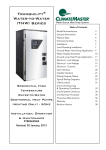
6XPPDU\
,QGRRU8QLW
*:+0%$'1$&,
*:+0%$'1$&,
2XWGRRU8QLW
*:+0%$'1$&2
*:+0%$'1$&2
5HPRWH&RQWUROOHU
<%)$)0272
MODE
ON/OFF
FAN
CLOCK
7HFKQLFDO,QIRUPDWLRQ
TIMER ON
X-FAN
TEMP
TIMER OFF
TURBO
SLEEP
LIGHT
6HUYLFH0DQXDO
6SHFL¿FDWLRQV
6SHFL¿FDWLRQ6KHHW
0RGHO
3URGXFW&RGH
5DWHG9ROWDJH
5DWHG)UHTXHQF\
3KDVHV
3RZHU6XSSO\0RGH
&RROLQJ&DSDFLW\0LQa0D[
+HDWLQJ&DSDFLW\0LQa0D[
&RROLQJ3RZHU,QSXW0LQa0D[
+HDWLQJ3RZHU,QSXW0LQa0D[
&RROLQJ&XUUHQW,QSXW
+HDWLQJ&XUUHQW,QSXW
5DWHG,QSXW
5DWHG&XUUHQW
$LU)ORZ9ROXPH6++0/
'HKXPLGLI\LQJ9ROXPH
((5
&23
6((5
+63)
$SSOLFDWLRQ$UHD
,QGRRU8QLW0RGHO
,QGRRU8QLW3URGXFW&RGH
,QGRRU8QLW)DQ7\SH
,QGRRU8QLW)DQ'LDPHWHU/HQJWK';/
&RROLQJ6SHHG6++0/
+HDWLQJ6SHHG6++0/
,QGRRU8QLW)DQ0RWRU3RZHU2XWSXW
,QGRRU8QLW)DQ0RWRU5/$
,QGRRU8QLW)DQ0RWRU&DSDFLWRU
+HDWHU3RZHU,QSXW
(YDSRUDWRU)RUP
(YDSRUDWRU3LSH'LDPHWHU
,QGRRU8QLW
(YDSRUDWRU5RZ¿Q*DS
(YDSRUDWRU&RLO/HQJWK/;';:
6ZLQJ0RWRU0RGHO
6ZLQJ0RWRU3RZHU2XWSXW
)XVH&XUUHQW
6RXQG3UHVVXUH/HYHO6++0/
6RXQG3RZHU/HYHO6++0/
'LPHQVLRQ:;+;'
'LPHQVLRQRI&DUWRQ%R[/;:;+
'LPHQVLRQRI3DFNDJH/;:;+
,QGRRU8QLW1HW:HLJKW
,QGRRU8QLW*URVV:HLJKW
3RZHU
6XSSO\
9a
+]
%WXK
%WXK
:
:
$
$
:
$
&)0
3LQWK
%WXK:
%WXK:
\G
LQFK
UPLQ
UPLQ
:
$
ȝ)
:
LQFK
LQFK
LQFK
:
$
G%$
G%$
LQFK
LQFK
LQFK
OE
OE
*:+0%$'1$&
&%
2XWGRRU
a
a
a
a
*:+0%$'1$&,
&%1
&URVVÀRZ
ĭ;
$OXPLQXP)LQFRSSHU7XEH
ĭ
;;
03$$
;;
;;
;;
7HFKQLFDO,QIRUPDWLRQ
6HUYLFH0DQXDO
2XWGRRU8QLW0RGHO
*:+0%$'1$&2
2XWGRRU8QLW3URGXFW&RGH
&%:
&RPSUHVVRU0DQXIDFWXUHU
=+8+$,/$1'$&2035(6625&2/7'
&RPSUHVVRU0RGHO
4;$$](
&RPSUHVVRU2LO
)9&'5%(3
&RPSUHVVRU7\SH
5RWDU\
&RPSUHVVRU/5$
$
&RPSUHVVRU5/$
$
&RPSUHVVRU3RZHU,QSXW
:
&RPSUHVVRU2YHUORDG3URWHFWRU
17/
7KURWWOLQJ0HWKRG
(OHFWURQH[SDQVLRQYDOYH
6HW7HPSHUDWXUH5DQJH
)
a
&RROLQJ2SHUDWLRQ$PELHQW7HPSHUDWXUH5DQJH
)
a
+HDWLQJ2SHUDWLRQ$PELHQW7HPSHUDWXUH5DQJH
)
&RQGHQVHU)RUP
2XWGRRU8QLW
a
$OXPLQXP)LQFRSSHU7XEH
&RQGHQVHU3LSH'LDPHWHU
LQFK
ĭ
&RQGHQVHU5RZV¿Q*DS
LQFK
&RQGHQVHU&RLO/HQJWK/;';:
LQFK
;;
2XWGRRU8QLW)DQ0RWRU6SHHG
USP
:
2XWGRRU8QLW)DQ0RWRU5/$
$
2XWGRRU8QLW)DQ0RWRU&DSDFLWRU
ȝ)
&)0
2XWGRRU8QLW)DQ0RWRU3RZHU2XWSXW
2XWGRRU8QLW$LU)ORZ9ROXPH
2XWGRRU8QLW)DQ7\SH
2XWGRRU8QLW)DQ'LDPHWHU
$[LDOÀRZ
LQFK
'HIURVWLQJ0HWKRG
$XWRPDWLF'HIURVWLQJ
&OLPDWH7\SH
7
,VRODWLRQ
,
0RLVWXUH3URWHFWLRQ
'HVLJQ3UHVVXUH+LJK
ĭ
,3
36,*
'HVLJQ3UHVVXUH/RZ
36,*
6RXQG3UHVVXUH/HYHO+0/
G%$
6RXQG3RZHU/HYHO+0/
G%$
'LPHQVLRQ:;+;'
LQFK
;;
'LPHQVLRQRI&DUWRQ%R[/;:;+
LQFK
;;
'LPHQVLRQRI3DFNDJH/;:;+
LQFK
;;
2XWGRRU8QLW1HW:HLJKW
OE
2XWGRRU8QLW*URVV:HLJKW
OE
5HIULJHUDQW
5HIULJHUDQW&KDUJH
&RQQHFWLRQ3LSH/HQJWK
&RQQHFWLRQ3LSH*DV$GGLWLRQDO&KDUJH
&RQQHFWLRQ 2XWHU'LDPHWHU/LTXLG3LSH
3LSH
2XWHU'LDPHWHU*DV3LSH
5$
R]
IW
R]IW
LQFK
LQFK
0D['LVWDQFH+HLJKW
IW
0D['LVWDQFH/HQJWK
IW
7KHDERYHGDWDLVVXEMHFWWRFKDQJHZLWKRXWQRWLFH3OHDVHUHIHUWRWKHQDPHSODWHRIWKHXQLW
7HFKQLFDO,QIRUPDWLRQ
6HUYLFH0DQXDO
0RGHO
*:+0%$'1$&
3URGXFW&RGH
3RZHU
6XSSO\
&%
5DWHG9ROWDJH
9a
5DWHG)UHTXHQF\
+]
3KDVHV
3RZHU6XSSO\0RGH
2XWGRRU
&RROLQJ&DSDFLW\0LQa0D[
%WXK
a
+HDWLQJ&DSDFLW\0LQa0D[
%WXK
a
&RROLQJ3RZHU,QSXW0LQa0D[
:
a
+HDWLQJ3RZHU,QSXW0LQa0D[
:
a
&RROLQJ&XUUHQW,QSXW
$
+HDWLQJ&XUUHQW,QSXW
$
5DWHG,QSXW
:
5DWHG&XUUHQW
$
$LU)ORZ9ROXPH6++0/
&)0
'HKXPLGLI\LQJ9ROXPH
3LQWK
((5
%WXK:
&23
%WXK:
6((5
+63)
$SSOLFDWLRQ$UHD
\G
,QGRRU8QLW0RGHO
*:+0%$'1$&,
,QGRRU8QLW3URGXFW&RGH
&%1
,QGRRU8QLW)DQ7\SH
&URVVÀRZ
,QGRRU8QLW)DQ'LDPHWHU/HQJWK';/
LQFK
ĭ;
&RROLQJ6SHHG6++0/
UPLQ
+HDWLQJ6SHHG6++0/
UPLQ
,QGRRU8QLW)DQ0RWRU3RZHU2XWSXW
:
,QGRRU8QLW)DQ0RWRU5/$
$
,QGRRU8QLW)DQ0RWRU&DSDFLWRU
ȝ)
+HDWHU3RZHU,QSXW
:
(YDSRUDWRU)RUP
,QGRRU8QLW
$OXPLQXP)LQFRSSHU7XEH
(YDSRUDWRU3LSH'LDPHWHU
LQFK
(YDSRUDWRU5RZ¿Q*DS
LQFK
(YDSRUDWRU&RLO/HQJWK/;';:
LQFK
;;
6ZLQJ0RWRU0RGHO
ĭ
03$$
6ZLQJ0RWRU3RZHU2XWSXW
:
)XVH&XUUHQW
$
6RXQG3UHVVXUH/HYHO6++0/
G%$
6RXQG3RZHU/HYHO6++0/
G%$
LQFK
;;
'LPHQVLRQ:;+;'
'LPHQVLRQRI&DUWRQ%R[/;:;+
LQFK
;;
'LPHQVLRQRI3DFNDJH/;:;+
LQFK
;;
,QGRRU8QLW1HW:HLJKW
OE
,QGRRU8QLW*URVV:HLJKW
OE
7HFKQLFDO,QIRUPDWLRQ
6HUYLFH0DQXDO
2XWGRRU8QLW0RGHO
*:+0%$'1$&2
2XWGRRU8QLW3URGXFW&RGH
&%:
&RPSUHVVRU0DQXIDFWXUHU
=+8+$,/$1'$&2035(6625&2/7'
&RPSUHVVRU0RGHO
4;$$](
&RPSUHVVRU2LO
)9&'5%(3
&RPSUHVVRU7\SH
&RPSUHVVRU/5$
5RWDU\
$
&RPSUHVVRU5/$
$
&RPSUHVVRU3RZHU,QSXW
:
&RPSUHVVRU2YHUORDG3URWHFWRU
17/
7KURWWOLQJ0HWKRG
(OHFWURQH[SDQVLRQYDOYH
6HW7HPSHUDWXUH5DQJH
)
a
&RROLQJ2SHUDWLRQ$PELHQW7HPSHUDWXUH5DQJH
)
a
+HDWLQJ2SHUDWLRQ$PELHQW7HPSHUDWXUH5DQJH
)
&RQGHQVHU)RUP
2XWGRRU8QLW
a
$OXPLQXP)LQFRSSHU7XEH
&RQGHQVHU3LSH'LDPHWHU
LQFK
ĭ
&RQGHQVHU5RZV¿Q*DS
LQFK
&RQGHQVHU&RLO/HQJWK/;';:
LQFK
;;
2XWGRRU8QLW)DQ0RWRU6SHHG
USP
2XWGRRU8QLW)DQ0RWRU3RZHU2XWSXW
:
2XWGRRU8QLW)DQ0RWRU5/$
$
2XWGRRU8QLW)DQ0RWRU&DSDFLWRU
2XWGRRU8QLW$LU)ORZ9ROXPH
ȝ)
&)0
2XWGRRU8QLW)DQ7\SH
2XWGRRU8QLW)DQ'LDPHWHU
$[LDOÀRZ
LQFK
'HIURVWLQJ0HWKRG
ĭ
$XWRPDWLF'HIURVWLQJ
&OLPDWH7\SH
7
,VRODWLRQ
,
0RLVWXUH3URWHFWLRQ
,3
'HVLJQ3UHVVXUH+LJK
36,*
'HVLJQ3UHVVXUH/RZ
36,*
6RXQG3UHVVXUH/HYHO+0/
G%$
6RXQG3RZHU/HYHO+0/
G%$
'LPHQVLRQ:;+;'
LQFK
;;
'LPHQVLRQRI&DUWRQ%R[/;:;+
LQFK
;;
'LPHQVLRQRI3DFNDJH/;:;+
LQFK
;;
2XWGRRU8QLW1HW:HLJKW
OE
2XWGRRU8QLW*URVV:HLJKW
OE
5HIULJHUDQW
5$
5HIULJHUDQW&KDUJH
R]
&RQQHFWLRQ3LSH/HQJWK
IW
R]IW
LQFK
&RQQHFWLRQ3LSH*DV$GGLWLRQDO&KDUJH
&RQQHFWLRQ 2XWHU'LDPHWHU/LTXLG3LSH
3LSH
2XWHU'LDPHWHU*DV3LSH
LQFK
0D['LVWDQFH+HLJKW
IW
0D['LVWDQFH/HQJWK
IW
7KHDERYHGDWDLVVXEMHFWWRFKDQJHZLWKRXWQRWLFH3OHDVHUHIHUWRWKHQDPHSODWHRIWKHXQLW
7HFKQLFDO,QIRUPDWLRQ
6HUYLFH0DQXDO
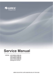
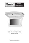
2SHUDWLRQ&KDUDFWHULVWLF&XUYH
Heating:
25.0 Conditions
22.5 Indoor: DB80°F/WB67°F
Outdoor: DB95°F/WB75°F
20.0
Indoor air flow: TURBO
17.5 Pipe length: 24.6 ft.
15.0
25.0
Conditions
Indoor: DB70°F/WB60°F
Outdoor: DB47°F/WB43°F
Indoor air flow: TURBO
Pipe length: 24.6 ft.
22.5
20.0
Current (A)
Current (A)
Cooling:
12.5
17.5
15.0
12.5
10.0
10.0
7.5
7.5
5.0
2.5
5.0
2.5
0
0
0
10
20
30
40
50
60
70
80
90
0
10 20 30 40 50 60 70 80 90 100 110 120
Compressor speed (rps)
Compressor speed (rps)
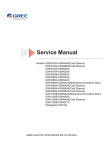
&DSDFLW\9DULDWLRQ5DWLR$FFRUGLQJWR7HPSHUDWXUH
Cooling:
Heating:
120
110
100
90
80
70
Conditions
Indoor: DB80°F/WB67°F
Indoor air flow: TURBO
Pipe length: 24.6 ft.
90 91 93 95 97 99 100 102 104 106 108 109 111 113 115
Outdoor temp. (˚F)
Capacity ratio (%)
Capacity ratio (%)
100
80
60
40
20
0
19
Conditions
Indoor: DB70°F/WB60°F
Indoor air flow: TURBO
Pipe length: 24.6 ft.
23
32
Outdoor temp. (˚F)
41
50
7HFKQLFDO,QIRUPDWLRQ
6HUYLFH0DQXDO
&RROLQJDQG+HDWLQJ'DWD6KHHWLQ5DWHG)UHTXHQF\
&RROLQJ
5DWHGFRROLQJFRQGLWLRQ)
'%:%
,QGRRU
2XWGRRU
3UHVVXUHRIJDVSLSH
,QOHWDQGRXWOHWSLSHWHPSHUDWXUH
FRQQHFWLQJLQGRRUDQG
)DQVSHHGRI )DQVSHHGRI &RPSUHVVRU
RIKHDWH[FKDQJHU
0RGHO
RXWGRRUXQLW
LQGRRUXQLW
RXWGRRUXQLW IUHTXHQF\+]
303D
7)
7)
.
.
WR
WR
WR
785%2
+LJK
WR
WR
785%2
+LJK
+HDWLQJ
3UHVVXUHRIJDVSLSH
5DWHGKHDWLQJFRQGLWLRQ)
'%:%
0RGHO
,QGRRU
2XWGRRU
.
.
FRQQHFWLQJLQGRRUDQG
RXWGRRUXQLW
303D
WR
,QOHWDQGRXWOHWSLSH
WHPSHUDWXUHRIKHDWH[FKDQJHU
)DQVSHHGRI )DQVSHHGRI &RPSUHVVRU
LQGRRUXQLW
RXWGRRUXQLW IUHTXHQF\+]
7)
7)
WR
WR
785%2
+LJK
WR
WR
785%2
+LJK
,QVWUXFWLRQ
7,QOHWDQGRXWOHWSLSHWHPSHUDWXUHRIHYDSRUDWRU
7,QOHWDQGRXWOHWSLSHWHPSHUDWXUHRIFRQGHQVHU
33UHVVXUHDWWKHVLGHRIELJYDOYH
&RQQHFWLRQSLSHOHQJWKIW
1RLVH&XUYH
Indoor side noise
Outdoor side noise
60
60
50
Noice/dB(A)
Noice/dB(A)
50
40
30
20
40
30
10
0
low
Middle
High
Super High
Indoor Fan Motor Rotating Speed
09K
7HFKQLFDO,QIRUPDWLRQ
20
0
20
40
60
80
100
Compressor frequency/Hz
12K
6HUYLFH0DQXDO
2XWOLQH'LPHQVLRQ'LDJUDP
,QGRRU8QLW
7
10 5/6
33 1/4
5 1/8
21 1/3
6 4/5
2 1/6
2 1/6
2 5/7
8QLWLQFK
4 7/8
2XWGRRU8QLW
10 1/8
H
30 5/9
W
D
21 1/4
11 1/4
8QLWLQFK
0RGHO
.
.
:
+
'
7HFKQLFDO,QIRUPDWLRQ
6HUYLFH0DQXDO
5HIULJHUDQW6\VWHP'LDJUDP
Outdoor unit
Indoor unit
Gas pipe
side
Valve
4-Way valve
Discharge
Heat
exchanger
(evaporator)
Suction
Heat
exchanger
(condenser)
Liquid pipe
side
Valve
Strainer
Electron
expansion
valve
Strainer
COOLING
HEATING
5HIULJHUDQWSLSHGLDPHWHU
/LTXLG*DV
7HFKQLFDO,QIRUPDWLRQ
6HUYLFH0DQXDO
(OHFWULFDO3DUW
:LULQJ'LDJUDP
Ɣ,QVWUXFWLRQ
6\PERO
6\PERO&RORU
6\PERO
6\PERO&RORU
6\PERO
1DPH
:+
:KLWH
*1
*UHHQ
&$3
-XPSHUFDS
<(
<HOORZ
%1
%URZQ
&203
&RPSUHVVRU
5'
5HG
%8
%OXH
<HOORZ*UHHQ
%.
%ODFN
9LROHW
2*
2UDQJH
<(*1
97
*URXQGLQJZLUH
1RWH-XPSHUFDSLVXVHGWRGHWHUPLQHIDQVSHHGDQGWKHVZLQJDQJOHRIKRUL]RQWDOORYHUIRUWKLVPRGHO
Ɣ,QGRRU8QLW
5220
78%(
7(06(1625 7(06(1625
57
',63/$<
$3
57
76(1625
1
',63 ',63 &20287
$&/
&$3
-803
$3
6:,1*8'
'&02725
0
0
6:,1*027258'
287'225 81,7
3(
/ %8 ;7
1
%.
%1
<(*1 <(*1
/
<(*1
&200$18$/
;7
1 1
/ 7(50,1$/
%/2&.
(9$325$725 (/(&75,&%2;
*
*
:,5('
&21752//(5
)$102725
:,5('&21752//(5
,6237,21$/
7HFKQLFDO,QIRUPDWLRQ
6HUYLFH0DQXDO
Ɣ2XWGRRU8QLW
:%8
/
:<(*1
:5'
/
&203
8 &203 ( :<(*1
9
:
/ / /
*
%8 <( 5'
78%(
2875220 (;+$867
7(06(1625 7(06(16257(06(1625
57
6$7
57
57
5'
$&1 $&1 $&/ $&/
(
29(5+($7
*
,1'225
81,7 ;7
1
7(50,1$/
%/2&.
:%.
&208
;7
),/7(5
/
/
:
:
1 1
$&1
%8
:+
/ :
/ :
$&/
/ %1 (
5'
:
:<(*1
+($7 +($71 +($7
<(*1
32:(5
/
1
*
*
(+
(+
+($7(5 +($7(5
&+$66,6&203
8
9
:
&1
$3
$&1 $&/ $&/
: : :
%8 2* %1
&
&
::+
9
&1
2)$1
(.9
0
$&1
<9
)$102725
*
7KHVHZLULQJGLDJUDPVDUHVXEMHFWWRFKDQJHZLWKRXWQRWLFHSOHDVHUHIHUWRWKHRQHVXSSOLHGZLWKWKHXQLW
7HFKQLFDO,QIRUPDWLRQ
6HUYLFH0DQXDO
3&%3ULQWHG'LDJUDP
,QGRRU8QLW
Ɣ7RSYLHZ
2
3
4
1
5
6
7
+HDOWKOLYHZLUHLQWHUIDFH
1HXWUDOZLUHLQWHUIDFH
+HDOWKQHXWUDOZLUHLQWHUIDFH
'&027(5LQWHUIDFH
-XPSFDS
$XWREXWWRQ
'LVSOD\LQWHUIDFH
8
9
11
8SGRZQVZLQJLQWHUIDFH
7XEH,QGRRUDPELHQWWHPSVHQVRU
LQWHUIDFH
1HXWUDODQGOLYHZLUH
FRPPXQLFDWLRQLQWHUIDFH
/LYHZLUHLQWHUIDFH
10
Ɣ%RWWRPYLHZ
7HFKQLFDO,QIRUPDWLRQ
6HUYLFH0DQXDO
2XWGRRU8QLW
Ɣ7RSYLHZ
1
2
3
4 5
6
7
8
9
12
1
EEV port
4
2
DC fan port
5
3
AC fan port
6
four-way valve port
compressor electric
heating band port
power supply live wire
port
11
10
7
power supply neutral
wire port
10
temp. sensor port
8
earth wire port
11
overload port
9
communication cable
interface
12
compressor output port
Ɣ%RWWRPYLHZ
7HFKQLFDO,QIRUPDWLRQ
6HUYLFH0DQXDO
)XQFWLRQDQG&RQWURO
5HPRWH&RQWUROOHU,QWURGXFWLRQ
Buttons on Remote Controller
1
ON/OFF Button
2
MODE Button
3
+/- Button
4
FAN Button
5
Button
6
CLOCK Button
7
TIMER ON/TIMER-OFF Button
8
X-FAN Button
2
1
3
4
5
6
8
7
9
TEMP Button
10
9
10
TURBO Button
12
11
11
LIGHT Button
12
SLEEP Button
Introduction for Icons on Display Screen
Operation mode
mode
Set fan speed
Send signal
Auto mode
Cool mode
X-fan mode
Dry mode
Fan mode
Heat mode
Set temperature
Turbo mode
Set time
Clock
TIMER ON/TIMER OFF
Sleep mode
Child lock
Temp. display
display type
type
:Set temp.
:Indoor ambient temp.
:Outdoor ambient temp.
Light
Up&down swing
Introduction for Buttons on Remote Controller
Note:After putting through the power, the air conditioner will give out a sound. Operation indictor "
you can operate the air conditioner by using remote controller.
" is ON (red indicator). After that,
1. ON/OFF Button
Press this button can turn on or turn off the air conditioner. After turning on the air conditioner, operation indicator "
unit’s display is ON (green indicator. The colour is different for different models), and indoor unit will give out a sound.
" on indoor
2. MODE Button
Press this button to select your required operation mode.
AUTO COOL DRY
FAN
HEAT
2QO\IRUPRGHOVZLWKKHDWLQJIXQFWLRQ
7HFKQLFDO,QIRUPDWLRQ
6HUYLFH0DQXDO
● When selecting auto mode, Air conditioner will start auto operation according to indoor ambient temperature.Set temperature can’t be
adjusted and will not be displayed as well. Press "FAN" button can adjust fan speed. Press " " button can adjust fan blowing angle.
" on indoor unit is ON. Press "+" or "-" button
● After selecting cool mode, air conditioner will operate under cool mode. Cool indicator "
to adjust set temperature. Press "FAN" button to adjust fan speed. Press " " button to adjust fan blowing angle.
● When selecting dry mode, the air conditioner operates at low speed under dry mode. Dry indicator " " on indoor unit is ON. Under dry
mode, fan speed can’t be adjusted. Press " " button to adjust fan blowing angle.
● When selecting fan mode, the air conditioner will only blow fan, no cooling and no heating.All indicators are OFF.Operation indicator is
ON.Press "FAN" button to adjust fan speed. Press " " button to adjust fan blowing angle.
● When selecting heating mode, the air conditioner operates under heat mode. Heat indicator " " on indoor unit is ON. Press “+” or “-“
button to adjust set temperature Press “FAN” button to adjust fan speed. Press " " button to adjust fan blowing angle.(Cooling only unit
won’t receive heating mode signal. If setting heat mode with remote controller, press ON/OFF button can’t start up the unit).
Note:
● For preventing cold air, after starting up heating mode, indoor unit will delay 1~5minutes to blow air (actual delay time is depend on
indoor ambient temperature).
● Set temperature range from remote controller: 16~30 ; Fan speed: auto, low speed,medium speed, high speed.
3. “+” or“-” Button
● Press “+” or “-“ button once increase or decrease set temperature 1
.Holding "+" or "-" button, 2s later, set temperature on remote
controller will change quickly. On releasing button after setting is finished, temperature indicator on indoor unit will change accordingly.
(Temperature can’t be adjusted under auto mode)
● When setting TIMER ON, TIMER OFF or CLOCK, press “+” or “-“ button to adjust time.(Refer to CLOCK, TIMER ON, TIMER OFF
buttons)
4. FAN Button
Pressing this button can set fan speed circularly as: auto (AUTO), low(
) ,medium(
),high(
).
Auto
Note:
● Under AUTO speed, the IDU fan motor will adjust the fan speed (high, medium or low speed) according to ambient temperature.
● Fan speed under dry mode is low speed.
5. Button
Pressing this button can select up&down swing angle. Fan blow angle can be selected circularly as below:
no display
(horizontal louvers
stops at current position)
● When selecting "
" , air conditioner is blowing fan automatically. Horizontal louver will automatically swing up & down at
maximum angle.
● When selecting " ǃ ǃ ǃ ǃ ", air conditioner is blowing fan at fixed position. Horizontal louver will stop at the fixed
position.
● When selecting " ǃ
ǃ
”, air conditioner is blowing fan at fixed angle. Horizontal louver will send air at the fixed angle.
● Hold " " button above 2s to set your required swing angle. When reaching your required angle, release the button.
Note:
" ǃ
ǃ
" may not be available. When air conditioner receives this signal, the air conditioner will blow fan automatically.
6. CLOCK Button
" icon on remote controller will blink. Pess "+" or "-" button within 5s to set clock time. Each
Press this button to set clock time. "
pressing of "+" or "-" button, clock time will increase or decrease 1 minute. Hold "+" or "-" button, 2s later, time will change quickly.
" icon stops blinking.
Release this button when reaching your required time. Press “CLOCK" button to confirm the time. "
Note:
● Clock time adopts 24-hour mode.
● The interval between two operation can’t exceeds 5s. Otherwise, remote controller will quit setting status. Operation for TIMER
ON/TIMER OFF is the same.
7. TIMER-ON/TIMER-OFF Button
● TIMER ON button
TIMER ON button
“TIMER ON” button can set the time for timer on. After pressing this button, "
7HFKQLFDO,QIRUPDWLRQ
" icon disappears and the word “ON" on remote
6HUYLFH0DQXDO
controller blinks. Press "+" or "-"button to adjust TIMER ON setting. After each pressing "+" or "-"button, TIMER ON setting will increase
or decrease 1min. Hold "+" or "-"button, 2s later, the time will change quickly
until reaching your required time. Press “ TIMER ON”to confirm it. The word “ON" will stop blinking. "
" icon resumes displaying.
Cancel TIMER ON: Under the condition that TIMER ON is started up, press “TIMER ON” button to cancel it.
● TIMER OFF button
"TIMER OFF" button can set the time for timer off. After pressing this button, "
" icon disappears and the word "OFF" on remote
controller blinks. Press "+" or "-" button to adjust TIMER OFF setting. After each pressing "+" or "-" button, TIMER OFF setting will
increase or decrease 1min. Hold "+" or "-" button, 2s later, the time will change
quickly until reaching your required time. Press "TIMER OFF" to confirm it .The word "OFF"will stop blinking "
" icon resumes
displaying. Cancel TIMER OFF. Under the condition that TIMER OFF is started up, press “TIMER OFF” button to cancel it.
Note:
● Under on and off status, you can set TIMER OFF or TIMER on simultaneously.
● Before setting TIMER ON or TIMER OFF, please adjust the clock time.
● After starting up TIMER ON or TIMER OFF, set the constant circulating valid. After that, air conditioner will be turned on or turned off
according to setting time. ON/OFF button has no effect on setting. If you don’t need this function, please use remote controller to cancel
it.
8. X-FAN Button
Press this button under cool and dry mode to start up x-fan function, and "
" icon on remote controller will be displayed. Press this
"icon will disappear.
button again to cancel x-fan function, and "
Note:
● When x-fan function is on, if the air conditioner is turned off, indoor fan will still operate at low speed for a while to blow the residual
water inside the air duct.
● During x-fan operation, press X-FAN button to turn off x-fan function. Indoor fan will stop operation immediately.
9. TEMP Button
By pressing this button, you can see indoor set temperature, indoor ambient temperature or outdoor ambient temperature on indoor
unit’s display. The setting on remote controlleris selected circularly as below:
no display
When selecting " " or no display with remote controller, temperature indicator on indoor unit displays set temperature;
When selecting " " with remote controller, temperature indicator on indoor unit displays indoor ambient temperature;
When selecting "
" with remote controller, temperature indicator on indoor unit displays outdoor ambient temperature.
Note:
● Outdoor temperature display is not available for some models. At that time, indoor unit receives"
" signal, while it displays
indoor set temperature.
● It’s defaulted to display set temperature when turning on the unit.There is no display in the remote controller.
● Only for the models whose indoor unit has dual-8 display
10. TURBO Button
Under COOL or HEAT mode, press this button to turn to quick COOL or quick HEAT mode. "
" icon will disappear.
controller. Press this button again to exit turbo function and "
" icon is displayed on remote
11. SLEEP Button
Under COOL, HEAT mode, press this button to start up sleep function. "
" icon will disappear.
again to cancel sleep function and "
" icon is displayed on remote controller. Press this button
12. LIGHT Button
Press this button to turn off display light on indoor unit. "
" icon is displayed.
on display light. "
" icon on remote controller disappears. Press this button again to turn
Function Introduction for Combination Buttons
Child lock function:
Press "+"and "-" simultaneously to turn on or turn off child lock function. When child lock function is on, " " icon is displayed on
remote controller. If you operate the remote controller, it won’t send signal.
Temperature display switchover function:
Under OFF status, press "-" and "MODE" buttons simultaneously to switch temperature display between
and
.
7HFKQLFDO,QIRUPDWLRQ
6HUYLFH0DQXDO
Operation Guide
1. After putting through the power, press “ON/OFF” button on remote controller to turn on
the air conditioner.
2. Press "MODE" button to select your required mode:AUTO,COOL,DRY,FAN,HEAT.
3. Press “+” or “-“ button to set your required temperature. (Temperature can’t be
adjusted under auto mode).
4. Press ‘FAN” button to set your required fan speed: auto, low, medium and high speed.
5. Press " " button to select fan blowing angle.
2
1
3
4
5
Replacement of Batteries in Remote Controller
1.Press the back side of remote controller marked with“
of battery box along the arrow direction.
”as shown in the fig, and then push out the cover
2. Replace two 7# (AAA 1.5V) dry batteries, and make sure the position of “+” polar and “-“ polar are correct.
3. Reinstall the cover of battery box.
Note:
● During operation, point the remote control signal sender at the receiving window
on indoor unit.
● The distance between signal sender and receiving window should be no more than
8m, and there should be no obstacles between them.
● Signal may be interfered easily in the room where there is fluorescent lamp or
wireless telephone; remote controller should be close to indoor unit during operation.
● Replace new batteries of the same model when replacement is required.
● When you don’t use remote controller for a long time, please take out the batteries.
● If the display on remote controller is fuzzy or there’s no display, please replace
batteries.
7HFKQLFDO,QIRUPDWLRQ
Signal sender
Battery
Reinstall
Cover of
battery box
Remove
6HUYLFH0DQXDO
%ULHI'HVFULSWLRQRI0RGHVDQG)XQFWLRQV
&RQYHUVLRQIRUPXODIRU)DKUHQKHLWGHJUHHDQG&HOVLXVGHJUHH7I 7F[
1. Temperature Parameters
ƹ Indoor preset temperature (Tpreset)
ƹ Indoor ambient temperature (T amb.)
2. Basic Functions
Once energized, in no case should the compressor be restarted within less than 3 minutes. In the situation that memory function is availthe compressor is in operation before de-energization, the compressor will be started with a 3-minute lag; and once started, the compressor will not be stopped within 6 minutes regardless of changes in room temperature.
(1)Cooling Mode
ķ The condition and process of cooling
If Tamb.≥Tpreset cooling mode will act, the compressor and outdoor fan will run, and the indoor fan will run at the set speed.
If Tamb.≤Tpreset-2°C, the compressor will stop, the outdoor fan will delay 30 seconds to stop, and the indoor fan will run at the set speed.
If Tpreset-2°C<Tamb.<Tpreset , the unit will keep running in the previous mode.
In this mode, the reversal valve will not be powered on and the temperature setting range is 16~30°C.
Tpreset
Start cooling
Tamb.
Original operating status
Tpreset –2 ˚C
≥ 6 min.
≥ 3 min.
30S
Compressor
Stop cooling
≥ 6 min.
30S
Outdoor fan
Set fan spee d
Indoor fan
ĸ Protection function
Run
Stop
ƹ Overcurrent protection
If total current is high, the compressor will run in limited frequency. If total current is too high , the compressor will stop, the outdoor fan will
delay 30 seconds to stop, indoor unit will display E5 and out door yellow light will blink 5 times.
ƹ Antifreezing protection
When the antifreezing protection is detected, the compressor will stop, the outdoor fan will stop after 30 seconds, and the indoor fan and
swing motor will keep running in the original mode. When antifreezing protection is eliminated and the compressor has stopped for 3 minutes, the compressor will resume running in the original mode.
During antifreeze protection
Compressor
30S
3 min
Outdoor fan
Preset speed
Indoor fan
Run
Stop
(2) Dehumidifying Mode
ķ Working conditions and process of dehumidifying
If Tamb.>Tpreset, the unit will enter cooling and dehumidifying mode, in which case the compressor and the outdoor fan will operate and the
indoor fan will run at low speed.
If Tpreset-2°C≤Tamb.≤Tpreset, the compressor remains at its original operation state.
If Tamb.< Tpreset-2°C, the compressor will stop, the outdoor fan will stop with a time lag of 30s, and the indoor fan will operate at low speed.
ĸ Protection function
Protection is the same as that under the cooling mode.
(3) Heating Mode
ķ The condition and process of heating
If Tamb.≤Tpreset+2°C, heating mode will act, the compressor, outdoor fan and reversal valve will run, the indoor fan will delay 3min to stop at
the latest
If Tpreset +2°C<Tamb.<Tpreset +5°C,the unit will keep running in the original mode.
If Tamb.≥Tpreset+5°C, the compressor will stop, the outdoor fan will delay 30s to stop and indoor fan will blow 60s at low speed, the fan speed
cannot be shifted within blow residual heat.
ƹ In this mode, the temperature setting range is 16 ~30°C.
ƹ The air conditioner will adjust the running frequency of the compressor automatically according to the change of ambient temperature.
ƹ When the unit is turned off in heating mode, or switched to other mode from heating mode, the four-way valve will be powered off after
the compressor stops.
7HFKQLFDO,QIRUPDWLRQ
6HUYLFH0DQXDO
ƹ When compressor is running (not including each malfunction and protection):
Stop heating
Tpreset+5
Original operating status
Tpreset+2
Tamb.
6min.
Compressor
3min.
Start heating
6min.
30s
30s
Outdoor fan
60s
Indoor fan <2 min.
preset
<2 min.
wind
60s
preset
wind
Reversing valve
Run
Stop
ĸ Condition and process of defrost
When duration of successive heating operation is more than 45 minutes, or accumulated heating time more than 90 minutes, and one of
the following conditions is reached, the unit will enter the defrost mode after 3 minutes.
(1). T outdoor ambient ˚ 5°C, T outdoor tube≤-2°C;
(2) -2°C≤T outdoor ambient ˘ 5°C, T outdoor tube -T compensatory ≤-6°C;
(3) -5°C≤T outdoor ambient ˘ -2°C, T outdoor tube -T compensatory ≤-8°C;
(4)-10°C≤T outdoor ambient ˘ -5°C, T outdoor tube-T compensatory ≤ (T outdoor ambient-5°C)
(5)T outdoor ambient ˘ -10°C, T outdoor tube-T compensatory ≤ (T outdoor ambient-5°C)
tube of quitting last defrosting: a. when T outdoor tube ˚ 2°C, T compensatory=0°C; b. when T outdoor tube ≤ 2°C, Tcompensatory=3°C)
At that time, the indoor fan stops and the compressor stops, and after 30 seconds the outdoor fan will stop, and then after 30 seconds,the
four-way valve will stop. After 30 seconds, the compressor is initiated for raising the frequency to defrost frequency.When the compressor has operated under defrost mode for 7.5 minutes, or T outdoor ambient ≥ 10°C, the compressor will be converted to 46Hz operation.
After 30 seconds, the compressor will stop. And after another 30 seconds, the four-way valve will be opened, and after 60 seconds, the
compressor and the oudoor fan will be started, the indoor fan will run under preset cold air prevention conditions,
Defrost frequency is 80Hz.
Ĺ Protection
ƹ Cold air prevention
The unit is started under heating mode (the compressor is ON):
ķ In the case of T indoor amb. <24°C: if T tube≤40°C and the indoor fan is at stop state, the indoor fan will begin to run at low speed with
a time lag of 2 minutes. Within 2 minutes, if T tube>40°C, the indoor fan also will run at low speed; and after 1-minute operation at low
speed, the indoor fan will be converted to operation at preset speed. Within 1-minute low speed operation or 2-minute nonoperation,if T
tube>42°C, the fan will run at present speed.
ĸ In the case of T indoor amb. ≥24°C: if T tube≤42°C, the indoor fan will run at low speed, and after one minute, the indoor fan will be
converted to preset speed. Within one-minute low speed operation, if T tube>42°C, the indoor fan will be converted to preset speed.
Note: T indoor amb. indicated in ķ and ĸ refers to, under initially heating mode, the indoor ambient temperature before the command to
start the compressor is performed according to the program, or after the unit is withdrawn from defrost, the indoor ambient temperature
before the defrost symbol is cleared.
ƹ Total current up and frequency down protection
If the total current Itotal≤W, frequency rise will be allowed; if Itotal≥X, frequency rise will not be allowed; if Itotal≥Y, the compressor will run at
reduced frequency; and if Itotal≥Z, the compressor will stop and the outdoor fan will stop with a time lag of 30s.
09k: W=12A;X=14A;Y=16A;Z=18A
12k: W=13A;X=15A;Y=17A;Z=19A
(5) Fan Mode
Under the mode, the indoor fan will run at preset speed and the compressor, the outdoor fan, the four-way valve and the electric heater will
stop.
Under the mode, temperature can be set within a range of 16~30°C.
(6)AUTO Mode
ķ Operation way of AUTO mode
a.When Tambient≥26°C, it will run in cooling mode. The implied set temperature is 25°C (note: the set temperature sending to outdoor
unit is 25°C).
b.For heating and cooling unit, when Tambient≤22°C, it will run in heating mode. The implied set temperature is 20°C;
for cooling only unit, when Tambient≤22°C, it will run in fan mode and the displayed set temperature is 25°C.
7HFKQLFDO,QIRUPDWLRQ
6HUYLFH0DQXDO
c.For heating and cooling unit, when 22°C<Tindoor ambient<26°C (for cooling only unit, 22°C<Tindoor ambient<26°C), it will keep the
ĸ Protection
a. In cooling operation, protection is the same as that under the cooling mode;
b. In heating operation, protection is the same as that under the heating mode;
c. When ambient temperature changes, operation mode will be converted preferentially. Once started, the compressor willremain
unchanged for at least 6 minutes.
(7)Common Protection Functions and Fault Display under COOL, HEAT, DRY and AUTO Modes
ķ Overload protection
Ttube: measured temperature of outdoor heat exchanger under cooling mode; and measured temperature of indoor heat exchanger under
heating mode.
1) Cooling overload
a.If T tube≤52°C, the unit will return to its original operation state.
b.If T tube≥55°C, frequency rise is not allowed.
c.If T tube≥58°C, the compressor will run at reduced frequency.
d.If T tube≥62°C, the compressor will stop and the indoor fan will run at preset speed.
2) Heating overload
a.If T tube≤50°C, the unit will return to its original operation state.
b.If T tube≥53°C, frequency rise is not allowed.
c.If T tube≥56°C, the compressor will run at reduced frequency.
d.If T tube≥60°C, the compressor will stop and the indoor fan will blow residue heat and then stop.
ĸ Exhaust temperature protection of compressor
If exhaust temperature≥98°C, frequency is not allowed to rise.
If exhaust temperature≥103°C, the compressor will run at reduced frequency.
If exhaust temperature≥110°C, the compressor will stop.
If exhaust temperature≤90°C and the compressor has stayed at stop for at least 3 minutes, the compressor will resume its operation.
Ĺ Communication fault
ĺ Module protection
Under module protection mode, the compressor will stop. When the compressor remains at stop for at least 3 minutes, the compressor will
resume its operation. If module protection occurs six times in succession, the compressor will not be started again.
Ļ Overload protection
If temperature sensed by the overload sensor is over 115 , the compressor will stop and the outdoor fan will stop with a time lag of 30
seconds. If temperature is below 95 , the overload protection will be relieved.
ļ DC bus voltage protection
If voltage on the DC bus is below 150V or over 420V, the compressor will stop and the outdoor fan will stop with a time lag of 30 seconds.
When voltage on the DC bus returns to its normal value and the compressor has stayed at stop for at least 3 minutes, the compressor will
resume its operation.
Ľ Faults of temperature sensors
Designation of sensors
Indoor ambient temperature
Indoor tube temperature
Outdoor ambient temperature
Outdoor tube temperature
Exhaust
Overload
Faults
The sensor is detected to be open-circuited or short-circuited for successive 5 seconds
The sensor is detected to be open-circuited or short-circuited for successive 5 seconds
The sensor is detected to be open-circuited or short-circuited for successive 30 seconds
The sensor is detected to be open-circuited or short-circuited for successive 30 seconds, and no
detection is performed within 10 minutes after defrost begins.
After the compressor has operated for 3 minutes, the sensor is detected to be open-circuited or
short-circuited for successive 30 seconds.
After the compressor has operated for 3 minutes, the sensor is detected to be open-circuited or
short-circuited for successive 30 seconds.
3. Other Controls
(1) ON/OFF
Press the remote button ON/OFF: the on-off state will be changed once each time you press the button.
(2) Mode Selection:
Press the remote button MODE, then select and show in the following ways: AUTO, COOL, DRY, FAN, HEAT, AUTO.
(3) Temperature Setting Option Button
Each time you press the remote button TEMP+ or TEMP-, the setting temperature will be up or down by 1°C. Regulating Range: 16~30°C,
the button is useless under the AUTO mode.
(4) Time Switch
You should start and stop the machine according to the setting time by remote control.
(5) SLEEP State Control
7HFKQLFDO,QIRUPDWLRQ
6HUYLFH0DQXDO
1. In cooling mode:
1.1 When the initial set temperature is16-23°C,the temperature will rise 1°C by every hour after sleep function is set;the temperature will
not change after rising 3°C;after running for 7hours,the temperature will decrease1°C and it will not change after that.
1.2 When the initial set temperature is 24-27°C,the temperature will rise 1°C by every hour after sleep function is set; the temperature will
not change after rising 2°C;after running for 7 hours, the temperature will decrease 1°C and it will not change after that.
1.3 When the initial set temperature is 28-29°C,the temperature will rise 1°C by every hour after sleep function is set; the temperature will
not change after rising 1°C; after running for 7 hours, the temperature will decrease 1°C and it will not change after that.
1.4 When the initial set temperature is 30°C, the unit will keep on running at this temperature; after running for 7 hours, the temperature will
decrease 1°C and it will not change after that.
Relationship between set temperature and running time:
Initial Temp.
0(start)
16
17
18
19
20
21
22
23
24
25
26
27
28
29
30
1
17
18
19
20
21
22
23
24
25
26
27
28
29
30
30
2
18
19
20
21
22
23
24
25
26
27
28
29
29
30
30
3
19
20
21
22
23
24
25
26
26
27
28
29
29
30
30
Running time(+RXU )
4
5
19
19
20
20
21
21
22
22
23
23
24
24
25
25
26
26
26
26
27
27
28
28
29
29
29
29
30
30
30
30
6
19
20
21
22
23
24
25
26
26
27
28
29
29
30
30
7
18
19
20
21
22
23
24
25
25
26
27
28
28
29
29
8
18
19
20
21
22
23
24
25
25
26
27
28
28
29
29
2. In heating mode:
2.1 When the initial set temperature is 16°C, the unit will keep on running at this temperature;
2.2 When the initial set temperature is 17-20°C, the temperature will decrease 1°C by every hour after sleep function is set; the temperature
will not change after decreasing 1°C;
2.3 When the initial set temperature is 21-27°C, the temperature will decrease 1°C by every hour after sleep function is set; the temperature
will not change after decreasing 2 ;
2.4 When the initial set temperature is 28-30°C, the temperature will decrease 1°C by every hour after sleep function is set; the temperature
will not change after decreasing 3°C;
Relationship between set temperature and running time:
Temp.
°C
0(start)
16
17
18
19
20
21
22
23
24
25
26
27
28
29
30
1
16
16
17
18
19
20
21
22
23
24
25
26
27
28
29
2
16
16
17
18
19
19
20
21
22
23
24
25
26
27
28
3
16
16
17
18
19
19
20
21
22
23
24
25
25
26
27
Running time(+RXU )
4
5
16
16
16
16
17
17
18
18
19
19
19
19
20
20
21
21
22
22
23
23
24
24
25
25
25
25
26
26
27
27
6
16
16
17
18
19
19
20
21
22
23
24
25
25
26
27
7
16
16
17
18
19
19
20
21
22
23
24
25
25
26
27
8
16
16
17
18
19
19
20
21
22
23
24
25
25
26
27
(6) Indoor Fan Control
Indoor fan could be set at ultra-high, high, medium, low speed by wireless remote controller and operated as that speed.
Auto fan speed could be set as well, indoor fan will operate under auto fan speed as following:
7HFKQLFDO,QIRUPDWLRQ
6HUYLFH0DQXDO
1. Under heating mode: auto speed under heating or auto heating mode:
a. When Tamb.≤Tpreset+1°C, indoor fan will operate at high speed;
b. When Tpreset+1°C<Tamb.<Tpreset+3°C, indoor fan will operate at medium speed;
c. When Tamb.≥Tpreset+3°C, indoor fan will operate at low speed;
There should be at least 180s operation time during switchover of each speed.
2. Under cooling mode: auto speed under cooling or auto cooling mode:
a. When Tamb.≥Tpreset+2°C, indoor fan will operate at high speed;
b. When Tpreset<Tamb.<Tpreset+2°C, indoor fan will operate at medium speed;
c. When Tamb.≤Tpreset, indoor fan will operate at low speed
There should be at least 210s operation time during switchover of each speed.
(7) Buzzer Control
The buzzer will send a “Di” sound when the air conditioner is powered up or received the information sent by the remote control or there is
a button input, the single tube cooler doesn’t receive the remote control ON signal under the mode of heating mode.
(8) Auto button
If the controller is on, it will stop by pressing the button, and if the controller is off, it will be automatic running state by pressing the button,
swing on and light on, and the main unit will run based on the remote control if there is remote control order.
(9) Up-and-Down Swinging Control
Cooling angle
Heating angle
O(0°)
O(0°)
After starting the machine, if you don’t set the swinging functi on,
will move to D clockwise; under other modes, the up-and-down air
L1
A1
B1
L
A
B
C
D
C1
the machine, then the wind blade will swing between L and D. The air
D1
Location D, Location L to Location D, stop at any location between L-D (the included angle between L~D is the same).
fectual only on condition that setting the swinging order and the inner
(10) Display
ķ Operation pattern and mode pattern display
All the display patterns will display for a time when the power on, the operation indication pattern will display in red under standby status.
When the machine is start by remote control, the indication pattern will light and display the current operation mode (the mode light includes: Cooling, heating and dehumidify). If you close the light key, all the display patterns will close.
ĸDouble-8 display
According to the different setting of remote control, the nixie light may display the current temperature (the temperature scope is from 16°C
to 30°C) and indoor ambient temperature. The set temperature displayed in auto cooling and fan mode is 25°C and the set temperature
displayed in auto heating mode is 20°C. Under heating mode, nixie tube displays H1 or heating indicator is off 0.5s and blinks 10s in defrosting.(If you set the fahrenheit temperature display, the nixie light will display according to fahrenheit temperature)(11) Protection function
and failure display
F1: Indoor ambient sensor start and short circuit (continuously measured failure in 5s)
F2: Indoor evaporator sensor start and short circuit (continuously measured failure in 5s)
F3: Outdoor ambient sensor start and short circuit (continuously measured failure in 30s)
F4: Outdoor condenser sensor start and short circuit (continuously measured failure in 30s, and don’t measure within 10 minutes after
defrosted)
F5: Outdoor exhausting sensor start and short circuit (continuously measured failure in 30s after the compressor operated 3 minutes)
H3: Overload protection of compressor
H5: Module protection PH: High-voltage protection
PL: Low-voltage protection
P1: Nominal cooling and heating test
P2: Maximum cooling and heating test
P3: Medium cooling and heating test
P0: Minimum cooling and heating test
(12) Drying Function
You may start or stop the drying function under the modes of cooling and dehumidify at the starting status (The modes of automatism,
heating and air supply do not have drying function). When you start the drying function, after stop the machine by pressing the switch
button, you should keep running the inner fans for 2 minutes under low air damper (The swing will operate as the D1 status within 2
minutes, and other load is stopped), then stop the entire machine; When you stop the drying function, press the switch button will stop the
machine directly.When you start the drying function, operating the drying button will stop the inner fans and close the guide louver.
(13) Memory Function
When interrupting the power supply memory content: mode, swing function, light, set temperature and wind speed.
After interrupted the power supply, the machine will start when recovering the power according to the memory content automatically.
7HFKQLFDO,QIRUPDWLRQ
6HUYLFH0DQXDO
3DUWė ,QVWDOODWLRQDQG0DLQWHQDQFH
1RWHVIRU,QVWDOODWLRQDQG0DLQWHQDQFH
6DIHW\3UHFDXWLRQV
,PSRUWDQW
3OHDVHUHDGWKHVDIHW\SUHFDXWLRQVFDUHIXOO\EHIRUH
LQVWDOODWLRQDQGPDLQWHQDQFH
7KH IROORZLQJ FRQWHQWV DUH YHU\ LPSRUWDQW IRU LQVWDOODWLRQ
DQGPDLQWHQDQFH
3OHDVHIROORZWKHLQVWUXFWLRQVEHORZ
Ɣ7KHLQVWDOODWLRQRUPDLQWHQDQFHPXVWDFFRUGZLWKWKH
LQVWUXFWLRQV
Ɣ&RPSO\ZLWKDOOQDWLRQDOHOHFWULFDOFRGHVDQGORFDO
HOHFWULFDOFRGHV
Ɣ3D\DWWHQWLRQWRWKHZDUQLQJVDQGFDXWLRQVLQWKLV
PDQXDO
Ɣ$OOLQVWDOODWLRQDQGPDLQWHQDQFHVKDOOEHSHUIRUPHGE\
GLVWULEXWRURUTXDOL¿HGSHUVRQ
Ɣ$OOHOHFWULFZRUNPXVWEHSHUIRUPHGE\DOLFHQVHG
WHFKQLFLDQDFFRUGLQJWRORFDOUHJXODWLRQVDQGWKH
LQVWUXFWLRQVJLYHQLQWKLVPDQXDO
Ɣ%HFDXWLRQGXULQJLQVWDOODWLRQDQGPDLQWHQDQFH3URKLELW
LQFRUUHFWRSHUDWLRQWRSUHYHQWHOHFWULFVKRFNFDVXDOW\DQG
RWKHUDFFLGHQWV
:DUQLQJV
(OHFWULFDO6DIHW\3UHFDXWLRQV
&XWRIIWKHSRZHUVXSSO\RIDLUFRQGLWLRQHUEHIRUH
FKHFNLQJDQGPDLQWHQDQFH
7KHDLUFRQGLWLRQPXVWDSSO\VSHFLDOL]HGFLUFXLWDQG
SURKLELWVKDUHWKHVDPHFLUFXLWZLWKRWKHUDSSOLDQFHV
7KHDLUFRQGLWLRQHUVKRXOGEHLQVWDOOHGLQVXLWDEOH
ORFDWLRQDQGHQVXUHWKHSRZHUSOXJLVWRXFKDEOH
0DNHVXUHHDFKZLULQJWHUPLQDOLVFRQQHFWHG¿UPO\
GXULQJLQVWDOODWLRQDQGPDLQWHQDQFH
+DYHWKHXQLWDGHTXDWHO\JURXQGHG7KHJURXQGLQJ
ZLUHFDQ¶WEHXVHGIRURWKHUSXUSRVHV
0XVWDSSO\SURWHFWLYHDFFHVVRULHVVXFKDVSURWHFWLYH
ERDUGVFDEOHFURVVORRSDQGZLUHFOLS
7KHOLYHZLUHQHXWUDOZLUHDQGJURXQGLQJZLUHRI
SRZHUVXSSO\PXVWEHFRUUHVSRQGLQJWRWKHOLYHZLUH
QHXWUDOZLUHDQGJURXQGLQJZLUHRIWKHDLUFRQGLWLRQHU
7KHSRZHUFRUGDQGSRZHUFRQQHFWLRQZLUHVFDQ¶WEH
SUHVVHGE\KDUGREMHFWV
,ISRZHUFRUGRUFRQQHFWLRQZLUHLVEURNHQLWPXVWEH
UHSODFHGE\DTXDOL¿HGSHUVRQ
,QVWDOODWLRQDQG0DLQWHQDQFH
,IWKHSRZHUFRUGRUFRQQHFWLRQZLUHLVQRWORQJHQRXJK
SOHDVHJHWWKHVSHFLDOL]HGSRZHUFRUGRUFRQQHFWLRQZLUH
IURPWKHPDQXIDFWXUHRUGLVWULEXWRU3URKLELWSURORQJWKHZLUH
E\\RXUVHOI
)RUWKHDLUFRQGLWLRQHUZLWKRXWSOXJDQDLUVZLWFKPXVW
EHLQVWDOOHGLQWKHFLUFXLW7KHDLUVZLWFKVKRXOGEHDOOSROH
SDUWLQJDQGWKHFRQWDFWSDUWLQJGLVWDQFHVKRXOGEHPRUHWKDQ
LQFK
0DNHVXUHDOOZLUHVDQGSLSHVDUHFRQQHFWHGSURSHUO\DQG
WKHYDOYHVDUHRSHQHGEHIRUHHQHUJL]LQJ
&KHFNLIWKHUHLVHOHFWULFOHDNDJHRQWKHXQLWERG\,I\HV
SOHDVHHOLPLQDWHWKHHOHFWULFOHDNDJH
5HSODFHWKHIXVHZLWKDQHZRQHRIWKHVDPHVSHFL¿FDWLRQ
LILWLVEXUQWGRZQGRQ¶WUHSODFHLWZLWKDFRRSHUZLUHRU
FRQGXFWLQJZLUH
,IWKHXQLWLVWREHLQVWDOOHGLQDKXPLGSODFHWKHFLUFXLW
EUHDNHUPXVWEHLQVWDOOHG
,QVWDOODWLRQ6DIHW\3UHFDXWLRQV
6HOHFWWKHLQVWDOODWLRQORFDWLRQDFFRUGLQJWRWKHUHTXLUH
PHQWRIWKLVPDQXDO6HHWKHUHTXLUHPHQWVLQLQVWDOODWLRQ
SDUW
+DQGOHXQLWWUDQVSRUWDWLRQZLWKFDUHWKHXQLWVKRXOGQRW
EHFDUULHGE\RQO\RQHSHUVRQLILWLVPRUHWKDQOEV
:KHQLQVWDOOLQJWKHLQGRRUXQLWDQGRXWGRRUXQLWDVXI¿
FLHQW¿[LQJEROWPXVWEHLQVWDOOHGPDNHVXUHWKHLQVWDOODWLRQ
VXSSRUWLV¿UP
:DUHVDIHW\EHOWLIWKHKHLJKWRIZRUNLQJLVDERYHIW
8VHHTXLSSHGFRPSRQHQWVRUDSSRLQWHGFRPSRQHQWVGXU
LQJLQVWDOODWLRQ
0DNHVXUHQRIRUHLJQREMHFWVDUHOHIWLQWKHXQLWDIWHU¿Q
LVKLQJLQVWDOODWLRQ
5HIULJHUDQW6DIHW\3UHFDXWLRQV
$YRLGFRQWDFWEHWZHHQUHIULJHUDQWDQG¿UHDVLWJHQHUDWHV
SRLVRQRXVJDV3URKLELWSURORQJWKHFRQQHFWLRQSLSHE\
ZHOGLQJ
$SSO\VSHFL¿HGUHIULJHUDQWRQO\1HYHUKDYHLWPL[HGZLWK
DQ\RWKHUUHIULJHUDQW1HYHUKDYHDLUUHPDLQLQWKHUHIULJHUDQW
OLQHDVLWPD\OHDGWRUXSWXUHRURWKHUKD]DUGV
0DNHVXUHQRUHIULJHUDQWJDVLVOHDNLQJRXWZKHQ
LQVWDOODWLRQLVFRPSOHWHG
,IWKHUHLVUHIULJHUDQWOHDNDJHSOHDVHWDNHVXI¿FLHQW
PHDVXUHWRPLQLPL]HWKHGHQVLW\RIUHIULJHUDQW
1HYHUWRXFKWKHUHIULJHUDQWSLSLQJRUFRPSUHVVRUZLWKRXW
ZHDULQJJORYHWRDYRLGVFDOGRUIURVWELWH
,PSURSHULQVWDOODWLRQPD\OHDGWR¿UHKD]DUGH[SORVLRQ
HOHFWULFVKRFNRULQMXU\
6HUYLFH0DQXDO
0DLQ7RROVIRU,QVWDOODWLRQDQG0DLQWHQDQFH
/HYHOPHWHUPHDVXULQJWDSH
6FUHZGULYHU
,PSDFWGULOOGULOOKHDGHOHFWULFGULOO
(OHFWURSUREH
8QLYHUVDOPHWHU
7RUTXHZUHQFKRSHQHQGZUHQFKLQQHU
KH[DJRQVSDQQHU
(OHFWURQLFOHDNDJHGHWHFWRU
9DFXXPSXPS
3UHVVXUHPHWHU
3LSHSOLHUVSLSHFXWWHU
3LSHH[SDQGHUSLSHEHQGHU
6ROGHULQJDSSOLDQFHUHIULJHUDQWFRQWDLQHU
,QVWDOODWLRQDQG0DLQWHQDQFH
6HUYLFH0DQXDO
,QVWDOODWLRQ
At least 0.5ft.
Space to the ceiling
,QVWDOODWLRQ'LPHQVLRQ'LDJUDP
Space to the wall
Space to the wall
At least 0.5ft.
At least 8.2ft.
ft.
10
st
lea
At
ac
At
et
ot
lea
he
st
wa
the
o
et
ac
Sp
tr
bs
o
ft.
t1
as
ll
1ft
.
tio
uc
Sp
n
tio
uc
le
At
tr
bs
e
ac
At least 1.6ft.
Sp
Space to the obstruction
Sp
ac
et
ot
he
ob
str
uc
tio
Space to the floor
n
At least 0.5ft.
to
eo
th
At
st
lea
n
Drainage pipe
t.
f
6.6
Sp
At
ac
et
lea
st
ot
he
1.6
ft.
,QVWDOODWLRQDQG0DLQWHQDQFH
ob
str
uc
tio
n
6HUYLFH0DQXDO
,QVWDOODWLRQSURFHGXUHV
Start installation
Preparation before installation
Read the requirements
for electric connection
select installation
location
Select indoor unit
installation location
Prepare tools
Select outdoor unit
installation location
Install the support of outdoor unit
(select it according to the actual situation)
Install wall-mounting
frame, drill wall holes
Connect pipes of indoor
unit and drainage pipe
Fix outdoor unit
Connect wires of indoor unit
Install drainage joint of outdoor unit
(only for cooling and heating unit)
Bind up pipes and
hang the indoor unit
Make the bound pipes pass
through the wall hole and then
connect outdoor unit
Connect pipes of outdoor unit
Connect wires of outdoor unit
Neaten the pipes
Vacuum pumping and leakage detection
Check after installation and test operation
Finish installation
Note: this flow is only for reference; please find the more detailed installation steps in this section.
,QVWDOODWLRQDQG0DLQWHQDQFH
6HUYLFH0DQXDO
,QVWDOODWLRQ3DUWVFKHFNLQJ
1R
1DPH
,QGRRUXQLW
2XWGRRUXQLW
1R
&RQQHFWLRQSLSH
'UDLQDJHSLSH
:DOOPRXQWLQJ
IUDPH
&RQQHFWLQJ
FDEOHSRZHUFRUG
:DOOSLSH
1DPH
6HDOLQJJXP
:UDSSLQJWDSH
6XSSRUWRIRXWGRRU
XQLW
)L[LQJVFUHZ
'UDLQDJHSOXJFRROLQJ
DQGKHDWLQJXQLW
2ZQHU¶VPDQXDO
UHPRWHFRQWUROOHU
1RWH
3OHDVHFRQWDFWWKHORFDODJHQWIRULQVWDOODWLRQ
'RQ
WXVHXQTXDOL¿HGSRZHUFRUG
6HOHFWLRQRI,QVWDOODWLRQ/RFDWLRQ
%DVLF5HTXLUHPHQW
,QVWDOOLQJWKHXQLWLQWKHIROORZLQJSODFHVPD\FDXVH
PDOIXQFWLRQ,ILWLVXQDYRLGDEOHSOHDVHFRQVXOWWKHORFDOGHDOHU
7KHSODFHZLWKVWURQJKHDWVRXUFHVYDSRUVÀDPPDEOHRU
H[SORVLYHJDVRUYRODWLOHREMHFWVVSUHDGLQWKHDLU
7KH SODFH ZLWK KLJKIUHTXHQF\ GHYLFHV VXFK DV ZHOGLQJ
PDFKLQHPHGLFDOHTXLSPHQW
7KHSODFHQHDUFRDVWDUHD
7KHSODFHZLWKRLORUIXPHVLQWKHDLU
7KHSODFHZLWKVXOIXUHWHGJDV
2WKHUSODFHVZLWKVSHFLDOFLUFXPVWDQFHV
,QGRRU8QLW
7KHUHVKRXOGEHQRREVWUXFWLRQQHDUDLULQOHWDQGDLURXWOHW
6HOHFWDORFDWLRQZKHUHWKHFRQGHQVDWLRQZDWHUFDQEH
GLVSHUVHGHDVLO\DQGZRQ
WDIIHFWRWKHUSHRSOH
6HOHFWDORFDWLRQZKLFKLVFRQYHQLHQWWRFRQQHFWWKH
RXWGRRUXQLWDQGQHDUWKHSRZHUVRFNHW
6HOHFWDORFDWLRQZKLFKLVRXWRIUHDFKIRUFKLOGUHQ
7KHORFDWLRQVKRXOGEHDEOHWRZLWKVWDQGWKHZHLJKWRI
LQGRRUXQLWDQGZRQ
WLQFUHDVHQRLVHDQGYLEUDWLRQ
7KHDSSOLDQFHPXVWEHLQVWDOOHGIWDERYHÀRRU
'RQ
WLQVWDOOWKHLQGRRUXQLWULJKWDERYHWKHHOHFWULF
DSSOLDQFH
7KHDSSOLDQFHVKDOOQRWEHLQVWDOOHGLQWKHODXQGU\
2XWGRRU8QLW
6HOHFWDORFDWLRQZKHUHWKHQRLVHDQGRXWÀRZDLUHPLWWHGE\
WKHRXWGRRUXQLWZLOOQRWDIIHFWQHLJKERUKRRG
7KHORFDWLRQVKRXOGEHZHOOYHQWLODWHGDQGGU\LQZKLFKWKH
RXWGRRU XQLW ZRQ
W EH H[SRVHG GLUHFWO\ WR VXQOLJKW RU VWURQJ
ZLQG
7KH ORFDWLRQ VKRXOG EH DEOH WR ZLWKVWDQG WKH ZHLJKW RI
RXWGRRUXQLW
0DNHVXUHWKDWWKHLQVWDOODWLRQIROORZVWKHUHTXLUHPHQWRI
LQVWDOODWLRQGLPHQVLRQGLDJUDP
6HOHFWDORFDWLRQZKLFKLVRXWRIUHDFKIRUFKLOGUHQDQGIDU
DZD\ IURP DQLPDOV RU SODQWV,I LW LV XQDYRLGDEOH SOHDVH DGG
IHQFHIRUVDIHW\SXUSRVH
,QVWDOODWLRQDQG0DLQWHQDQFH
(OHFWULF&RQQHFWLRQ5HTXLUHPHQW
6DIHW\3UHFDXWLRQ
0XVWIROORZWKHHOHFWULFVDIHW\UHJXODWLRQVZKHQ LQVWDOOLQJ
WKHXQLW
$FFRUGLQJ WR WKH ORFDO VDIHW\ UHJXODWLRQV XVH TXDOLILHG
SRZHUVXSSO\FLUFXLWDQGDLUVZLWFK
0DNHVXUHWKHSRZHUVXSSO\PDWFKHVZLWKWKHUHTXLUHPHQW
RI DLU FRQGLWLRQHU 8QVWDEOH SRZHU VXSSO\ RU LQFRUUHFW ZLULQJ
PD\UHVXOWLQHOHFWULFVKRFN¿UHKD]DUGRUPDOIXQFWLRQ3OHDVH
LQVWDOO SURSHU SRZHU VXSSO\ FDEOHV EHIRUH XVLQJ WKH DLU
FRQGLWLRQHU
3URSHUO\FRQQHFWWKHOLYHZLUHQHXWUDOZLUHDQGJURXQGLQJ
ZLUHRISRZHUVRFNHW
%HVXUHWRFXWRIIWKHSRZHUVXSSO\EHIRUHSURFHHGLQJDQ\
ZRUNUHODWHGWRHOHFWULFLW\DQGVDIHW\
'RQRWSXWWKURXJKWKHSRZHUEHIRUH¿QLVKLQJLQVWDOODWLRQ
)RU DSSOLDQFHV ZLWK W\SH < DWWDFKPHQWWKH LQVWUXFWLRQV
VKDOOFRQWDLQWKHVXEVWDQFHRIWKHIROORZLQJ,IWKHVXSSO\FRUGLV
GDPDJHGLWPXVWEHUHSODFHGE\WKHPDQXIDFWXUHULWVVHUYLFH
DJHQWRUVLPLODUO\TXDOL¿HGSHUVRQVLQRUGHUWRDYRLGDKD]DUG
7KH WHPSHUDWXUH RI UHIULJHUDQWFLUFXLWZLOOEHKLJK SOHDVH
NHHSWKHLQWHUFRQQHFWLRQFDEOHDZD\IURPWKHFRSSHUWXEH
*URXQGLQJ5HTXLUHPHQW
7KHDLUFRQGLWLRQHULV¿UVWFODVVHOHFWULFDSSOLDQFH,WPXVW
EH SURSHUO\ JURXQGLQJ ZLWK VSHFLDOL]HG JURXQGLQJ GHYLFH
E\ D SURIHVVLRQDO 3OHDVH PDNH VXUH LW LV DOZD\V JURXQGHG
HIIHFWLYHO\RWKHUZLVHLWPD\FDXVHHOHFWULFVKRFN
7KH\HOORZJUHHQZLUHLQDLUFRQGLWLRQHULVJURXQGLQJZLUH
ZKLFKFDQ
WEHXVHGIRURWKHUSXUSRVHV
7KH JURXQGLQJ UHVLVWDQFH VKRXOG FRPSO\ ZLWK QDWLRQDO
HOHFWULFVDIHW\UHJXODWLRQV
7KH DSSOLDQFH PXVW EH SRVLWLRQHG VR WKDW WKH SOXJ LV
DFFHVVLEOH
$QDOOSROHGLVFRQQHFWLRQVZLWFKKDYLQJDFRQWDFWVHSDUDWLRQ
RI DW OHDVW LQFK LQ DOO SROHV VKRXOG EH FRQQHFWHG LQ IL[HG
ZLULQJ
,QFOXGLQJDQDLUVZLWFKZLWKVXLWDEOHFDSDFLW\SOHDVHQRWH
WKH IROORZLQJ WDEOH$LU VZLWFK VKRXOG EH LQFOXGHG PDJQHW
EXFNOH DQG KHDWLQJ EXFNOH IXQFWLRQ LW FDQ SURWHFW WKH FLUFXLW
VKRUWDQGRYHUORDG&DXWLRQSOHDVHGRQRWXVHWKHIXVHRQO\
IRUSURWHFWWKHFLUFXLW
,QVWDOODWLRQRI,QGRRU8QLW
&KRRVLQJ,QVWDOODWLRQ,RFDWLRQ
5HFRPPHQG WKH LQVWDOODWLRQ ORFDWLRQ WR WKH FOLHQW DQG WKHQ
FRQ¿UPLWZLWKWKHFOLHQW
,QVWDOO:DOOPRXQWLQJ)UDPH
+DQJ WKH ZDOOPRXQWLQJ IUDPH RQ WKH ZDOO DGMXVW LW LQ
KRUL]RQWDOSRVLWLRQZLWKWKHOHYHOPHWHUDQGWKHQSRLQWRXWWKH
VFUHZ¿[LQJKROHVRQWKHZDOO
'ULOOWKHVFUHZ¿[LQJKROHVRQWKHZDOOZLWKLPSDFWGULOOWKH
VSHFLILFDWLRQ RI GULOO KHDG VKRXOG EH WKH VDPH DV WKH SODVWLF
H[SDQVLRQSDUWLFOHDQGWKHQ¿OOWKHSODVWLFH[SDQVLRQSDUWLFOHV
6HUYLFH0DQXDO
LQWKHKROHV
)L[WKHZDOOPRXQWLQJIUDPHRQWKHZDOOZLWKWDSSLQJVFUHZV
67;7$DQGWKHQFKHFNLIWKHIUDPHLV¿UPO\LQVWDOOHGE\
SXOOLQJ WKH IUDPH ,I WKH SODVWLF H[SDQVLRQ SDUWLFOH LV ORRVH
SOHDVHGULOODQRWKHU¿[LQJKROHQHDUE\
,QVWDOO:DOOPRXQWLQJ)UDPH
&KRRVHWKHSRVLWLRQRISLSLQJKROHDFFRUGLQJWRWKHGLUHFWLRQ
RI RXWOHW SLSH7KH SRVLWLRQ RI SLSLQJ KROH VKRXOG EH D OLWWOH
ORZHUWKDQWKHZDOOPRXQWHGIUDPH$VVKRZLQ)LJ
Wall
Mark in the middle of it
Wall
Level meter
Space
to the
wall
above
5 8/9
inch
Space
to the
wall
above
5 8/9
inch
Left
Φ2 1/6inch
Rear piping hole
)LJ
&RQQHFWWKH3LSHRI,QGRRU8QLW
$LPWKHSLSHMRLQWDWWKHFRUUHVSRQGLQJEHOOPRXWK$VVKRZ
LQ)LJ
3UHWLJKWHQLQJWKHXQLRQQXWZLWKKDQG
$GMXVWWKHWRUTXHIRUFHE\UHIHUULQJWRWKHIROORZLQJVKHHW
3ODFH WKH RSHQHQG ZUHQFK RQ WKH SLSH MRLQW DQG SODFH WKH
WRUTXH ZUHQFK RQ WKH XQLRQ QXW7LJKWHQ WKH XQLRQ QXW ZLWK
WRUTXHZUHQFK$VVKRZLQ)LJ
:UDS WKH LQGRRU SLSH DQG MRLQW RI FRQQHFWLRQ SLSH ZLWK
LQVXODWLQJSLSHDQGWKHQZUDSLWZLWKWDSH$VVKRZLQ)LJ
Open-end
wrench
Union nut
Pipe joint
Union nut
Right
Φ2 1/6inch
Rear piping hole
Pipe
)LJ
Indoor pipe
2SHQDSLSLQJKROHZLWKWKHGLDPHWHURILQFKRQWKH
VHOHFWHG RXWOHW SLSH SRVLWLRQ,Q RUGHU WR GUDLQ VPRRWKO\ VODQW
WKH SLSLQJ KROH RQ WKH ZDOO VOLJKWO\ GRZQZDUG WR WKH RXWGRRU
VLGHZLWKWKHJUDGLHQWRI$VVKRZLQ)LJ
Indoor
Pipe
Torque wrench
)LJ
Insulating pipe
)LJ
Outdoor
5HIHUWRWKHIROORZLQJWDEOHIRUZUHQFKPRPHQWRIIRUFH
+H[QXWGLDPHWHULQFK
ĭ
ĭ
ĭ
ĭ
ĭ
2 1/6inch
e
)LJ
1RWH
3D\ DWWHQWLRQ WR GXVW SUHYHQWLRQ DQG WDNH UHOHYDQW VDIHW\
PHDVXUHVZKHQRSHQLQJWKHKROH
7KHSODVWLFH[SDQVLRQSDUWLFOHVDUHQRWSURYLGHGDQGVKRXOG
EHERXJKWORFDOO\
7LJKWHQLQJWRUTXHIWÂ,EI
a
a
a
a
a
,QVWDOO'UDLQ+RVH
&RQQHFWWKHGUDLQKRVHWRWKHRXWOHWSLSHRILQGRRUXQLW$V
VKRZLQ)LJ
%LQGWKHMRLQWZLWKWDSH$VVKRZLQ)LJ
2XWOHW3LSH
7KHSLSHFDQEHOHGRXWLQWKHGLUHFWLRQRIULJKWUHDUULJKW
OHIWRUUHDUOHIW$VVKRZLQ)LJ
:KHQVHOHFWLQJOHDGLQJRXWWKHSLSHIURPOHIWRUULJKWSOHDVH
FXWRIIWKHFRUUHVSRQGLQJKROHRQWKHERWWRPFDVH$VVKRZLQ
)LJ
Drain hose
Outlet pipe
)LJ
Outlet
pipe
Drain hose
Tape
)LJ
1RWH
Left
)LJ
Left
Right
Cut off
the hole
Right
Rear right
Rear left
$GG LQVXODWLQJ SLSH LQ WKH LQGRRU GUDLQ KRVH LQ RUGHU WR
SUHYHQWFRQGHQVDWLRQ
7KHSODVWLFH[SDQVLRQSDUWLFOHVDUHQRWSURYLGHG
$VVKRZLQ)LJ
Drain hose
)LJ
Insulating pipe
)LJ
,QVWDOODWLRQDQG0DLQWHQDQFH
6HUYLFH0DQXDO
&RQQHFW:LUHRI,QGRRU8QLW
%LQGXS3LSH
2SHQWKHSDQHOUHPRYHWKHVFUHZRQWKHZLULQJFRYHUDQG
WKHQWDNHGRZQWKHFRYHU$VVKRZLQ)LJ
%LQG XS WKH FRQQHFWLRQ SLSH SRZHU FRUG DQG GUDLQ KRVH
ZLWKWKHEDQG$VVKRZLQ)LJ
5HVHUYH D FHUWDLQ OHQJWK RI GUDLQ KRVH DQG SRZHU FRUG
IRULQVWDOODWLRQZKHQELQGLQJWKHP:KHQELQGLQJWRDFHUWDLQ
GHJUHHVHSDUDWHWKHLQGRRUSRZHUDQGWKHQVHSDUDWHWKHGUDLQ
KRVH$VVKRZLQ)LJ
%LQGWKHPHYHQO\
7KHOLTXLGSLSHDQGJDVSLSHVKRXOGEHERXQGVHSDUDWHO\DW
WKHHQG
Panel
Screw
)LJ
Wiring cover
)L[ WKH ZLUH FURVVLQJ ERDUG RQ FRQQHFWLRQ ZLUH VOHHYH DW
WKHERWWRPFDVHOHWWKHFRQQHFWLRQZLUHVOHHYHJRWKURXJKWKH
ZLUHFURVVLQJKROHDWWKHEDFNRILQGRRUXQLWDQGWKHQSXOOLWRXW
IURPWKHIURQW$VVKRZLQ)LJ
Indoor and
outdoor power cord
Indoor unit
Gas
pipe
)LJ
Liquid
pipe
Band
Drain hose
connection wire sleeve
)LJ
5HPRYHWKHZLUHFOLSFRQQHFWWKHSRZHUFRQQHFWLRQZLUH
WRWKHZLULQJWHUPLQDOWLJKWHQWKHVFUHZDQGWKHQ¿[WKHSRZHU
FRQQHFWLRQZLUHZLWKZLUHFOLS$VVKRZLQ)LJ
Indoor unit
Wring Cover
N(1)
2
3
Connection pipe
Drain hose
Band
)LJ
Indoor power cord
1RWH
7KH SRZHU FRUG DQG FRQWURO ZLUH FDQ
W EH FURVVHG RU
ZLQGLQJ
7KHGUDLQKRVHVKRXOGEHERXQGDWWKHERWWRP
+DQJWKH,QGRRU8QLW
N
L
N(1)
2
3
Outdoor unit
)LJ
3XWZLULQJFRYHUEDFNDQGWKHQWLJKWHQWKHVFUHZ
&ORVHWKHSDQHO
1RWH
$OO ZLUHV RI LQGRRU XQLW DQG RXWGRRU XQLW VKRXOG EH
FRQQHFWHGE\DSURIHVVLRQDO
,IWKHOHQJWKRISRZHUFRQQHFWLRQZLUHLVLQVXI¿FLHQWSOHDVH
FRQWDFWWKHVXSSOLHUIRUDQHZRQH$YRLGH[WHQGLQJWKHZLUHE\
\RXUVHOI
)RU WKH DLU FRQGLWLRQHU ZLWK SOXJ WKH SOXJ VKRXOG EH
UHDFKDEOHDIWHU¿QLVKLQJLQVWDOODWLRQ
)RUWKHDLUFRQGLWLRQHUZLWKRXWSOXJDQDLUVZLWFKPXVWEH
LQVWDOOHG LQ WKH OLQH7KH DLU VZLWFK VKRXOG EH DOOSROH SDUWLQJ
DQGWKHFRQWDFWSDUWLQJGLVWDQFHVKRXOGEHPRUHWKDQLQFK
,QVWDOODWLRQDQG0DLQWHQDQFH
3XWWKHERXQGSLSHVLQWKHZDOOSLSHDQGWKHQPDNHWKHP
SDVVWKURXJKWKHZDOOKROH
+DQJWKHLQGRRUXQLWRQWKHZDOOPRXQWLQJIUDPH
6WXIIWKHJDSEHWZHHQSLSHVDQGZDOOKROHZLWKVHDOLQJJXP
)L[WKHZDOOSLSH$VVKRZLQ)LJ
&KHFNLIWKHLQGRRUXQLWLVLQVWDOOHG¿UPO\DQGFORVHGWRWKH
ZDOO$VVKRZLQ)LJ
Indoor
Wall pipe
Outdoor
)LJ
Sealing gum
Upper hook
)LJ
Lower hook of
wall-mounting frame
1RWH
'RQRWEHQGWKHGUDLQKRVHWRRH[FHVVLYHO\LQRUGHUWRSUHYHQW
EORFNLQJ
6HUYLFH0DQXDO
,QVWDOODWLRQRI2XWGRRU8QLW
)L[WKH6XSSRUWRI2XWGRRU8QLWVHOHFWLWDFFRUGLQJWRWKH
DFWXDOLQVWDOODWLRQVLWXDWLRQ
5HIHUWRWKHIROORZLQJWDEOHIRUZUHQFKPRPHQWRIIRUFH
+H[QXWGLDPHWHULQFK
ĭ
ĭ
ĭ
ĭ
ĭ
6HOHFWLQVWDOODWLRQORFDWLRQDFFRUGLQJWRWKHKRXVHVWUXFWXUH
)L[WKHVXSSRUWRIRXWGRRUXQLWRQWKHVHOHFWHGORFDWLRQZLWK
H[SDQVLRQVFUHZV
1RWH
7DNH VXIILFLHQW SURWHFWLYH PHDVXUHV ZKHQ LQVWDOOLQJ WKH
RXWGRRUXQLW
0DNHVXUHWKHVXSSRUWFDQZLWKVWDQGDWOHDVWIRXUWLPHVWKH
XQLWZHLJKW
7KH RXWGRRU XQLW VKRXOG EH LQVWDOOHG DW OHDVW LQFK
DERYHWKHÀRRULQRUGHUWRLQVWDOOGUDLQMRLQW$VVKRZLQ)LJ
)RU WKH XQLW ZLWK FRROLQJ FDSDFLW\ RI :a: H[SDQVLRQVFUHZVDUHQHHGHGIRUWKHXQLWZLWKFRROLQJFDSDFLW\
RI :a: H[SDQVLRQ VFUHZV DUH QHHGHG IRU WKH
XQLWZLWKFRROLQJFDSDFLW\RI:a:H[SDQVLRQ
VFUHZVDUHQHHGHG
7LJKWHQLQJWRUTXHIWÂ,EI
a
a
a
a
a
&RQQHFW2XWGRRU(OHFWULF:LUH
5HPRYHWKHFDEOHFURVVLQJERDUGRIULJKWVLGHSODWHIRU
RXWGRRUXQLW
5HPRYHWKHZLUHFODPSVSDVVWKHSRZHUFRQQHFWLRQZLUH
DQGSRZHUFRUGWKURXJKWKHFDEOHFURVVLQJERDUGWRFRQQHFW
WKHWHUPLQDO
7KHZLULQJGLVWULEXWLRQPXVWPDWFKZLWKWKHHOHFWULFGLDJUDP
)L[WKHSRZHUFRQQHFWLRQZLUHDQGSRZHUFRUGZLWKZLUH
FODPSVWLJKWO\
&KHFNZKHWKHUWKHZLULQJLV¿[HGZHOO
,QVWDOOWKHFDEOHFURVVLQJERDUG
Cable-Crossing board 2
Outdoor unit
Drain vent
At least 1 1/6 inch
above the floor
2 3
Chassis
Outdoor drain joint
Drain hose
2
)LJ
)LJ
,QVWDOO'UDLQ-RLQW2QO\IRUFRROLQJDQGKHDWLQJXQLW
&RQQHFWWKHRXWGRRUGUDLQMRLQWLQWRWKHKROHRQWKHFKDVVLV
&RQQHFWWKHGUDLQKRVHLQWRWKHGUDLQYHQW
$VVKRZLQ)LJ
)L[2XWGRRU8QLW
3ODFHWKHRXWGRRUXQLWRQWKHVXSSRUW
)L[WKHIRRWKROHVRIRXWGRRUXQLWZLWKEROWV
$VVKRZLQ)LJ
9DOYH&RYHU
)LJ
)LJ
&RQQHFW,QGRRUDQG2XWGRRU3LSHV
5HPRYHWKHVFUHZRQWKHFDEOHFURVVLQJERDUGDQGYDOYH
FRYHURIRXWGRRUXQLWDQGWKHQUHPRYHWKHFDEOHFURVVLQJERDUG
DQGYDOYHFRYHU$VVKRZLQ)LJ
5HPRYHWKHVFUHZFDSRIYDOYHDQGDLPWKHSLSHMRLQWDWWKH
EHOOPRXWKRISLSH$VVKRZLQ)LJ
Liquid pipe
L
N
3
Indoor unit
Cable-Crossing board 1
1RWH
6FUHZ
&DEOH&URVVLQJ
ERDUG
Liquid
valve
POWER
)LJ
Foot holes
Foot holes
L
N
$IWHU WLJKWHQLQJ WKH VFUHZ SXOO WKH SRZHU FRUG VOLJKWO\ WR
FKHFNLILWLV¿UP
1HYHUFXWWKHSRZHUFRQQHFWLRQZLUHWRSURORQJRUVKRUWHQ
WKHGLVWDQFH
1HDWHQWKH3LSHV
7KHSLSHVVKRXOGEHSODFHGDORQJWKHZDOOEHQWUHDVRQDEO\
DQGKLGGHQSRVVLEO\0LQVHPLGLDPHWHURIEHQGLQJWKHSLSHLV
LQFK
,IWKHRXWGRRUXQLWLVKLJKHUWKDQWKHZDOOKROH\RXPXVWVHW
D 8VKDSHG FXUYH LQ WKH SLSH EHIRUH SLSH JRHV LQWR WKH URRP
LQ RUGHU WR SUHYHQW UDLQ IURP JHWWLQJ LQWR WKH URRP$V VKRZ LQ
)LJ
The drain hos
can't raise
upwards
Pipe joint
gas pipe
Wall
gas valve
Union nut
)LJ
)LJ
U-shaped curve
3UHWLJKWHQLQJWKHXQLRQQXWZLWKKDQG
7LJKWHQWKHXQLRQQXWZLWKWRUTXHZUHQFK
)LJ
Drain hose
,QVWDOODWLRQDQG0DLQWHQDQFH
6HUYLFH0DQXDO
1RWH
7KHWKURXJKZDOOKHLJKWRIGUDLQKRVHVKRXOGQ
WEHKLJKHU
WKDQWKHRXWOHWSLSHKROHRILQGRRUXQLW$VVKRZLQ)LJ
6ODQW WKH GUDLQ KRVH VOLJKWO\ GRZQZDUGV7KH GUDLQ KRVH
FDQ
WEHFXUYHGUDLVHGDQGÀXFWXDQWHWF$VVKRZLQ)LJ
7KHZDWHURXWOHWFDQ
WEHSODFHGLQZDWHULQRUGHUWRGUDLQ
VPRRWKO\$VVKRZLQ)LJ
&KHFN DIWHU ,QVWDOODWLRQ DQG 7HVW
2SHUDWLRQ
The drain hose can't be fluctuant
The drain hose
can't be fluctuant
/HDNDJH'HWHFWLRQ
:LWKOHDNDJHGHWHFWRU
&KHFNLIWKHUHLVOHDNDJHZLWKOHDNDJHGHWHFWRU
:LWKVRDSZDWHU
,IOHDNDJHGHWHFWRULVQRWDYDLODEOHSOHDVHXVHVRDSZDWHUIRU
OHDNDJHGHWHFWLRQ$SSO\VRDSZDWHUDWWKHVXVSHFWHGSRVLWLRQ
DQG NHHS WKH VRDS ZDWHU IRU PRUH WKDQ PLQ ,I WKHUH DUH DLU
EXEEOHVFRPLQJRXWRIWKLVSRVLWLRQWKHUH
VDOHDNDJH
&KHFNDIWHU,QVWDOODWLRQ
&KHFN DFFRUGLQJ WR WKH IROORZLQJ UHTXLUHPHQW DIWHU ILQLVKLQJ
LQVWDOODWLRQ
The water outlet
can't be placed
in water
The water
outlet can't be
fluctuant
)LJ
1R
)LJ
9DFXXP3XPSLQJDQG/HDN'HWHFWLRQ
8VH9DFXXP3XPS
5HPRYH WKH YDOYH FDSV RQ WKH OLTXLG YDOYH DQG JDV YDOYH
DQGWKHQXWRIUHIULJHUDQWFKDUJLQJYHQW
&RQQHFWWKHFKDUJLQJKRVHRISLH]RPHWHUWRWKHUHIULJHUDQW
FKDUJLQJYHQWRIJDVYDOYHDQGWKHQFRQQHFWWKHRWKHUFKDUJLQJ
KRVHWRWKHYDFXXPSXPS
2SHQWKHSLH]RPHWHUFRPSOHWHO\DQGRSHUDWHIRUPLQ
WRFKHFNLIWKHSUHVVXUHRISLH]RPHWHUUHPDLQVLQ03D
&ORVHWKHYDFXXPSXPSDQGPDLQWDLQWKLVVWDWXVIRUPLQ
WRFKHFN LI WKH SUHVVXUHRISLH]RPHWHUUHPDLQVLQ03D,I
WKHSUHVVXUHGHFUHDVHVWKHUHPD\EHOHDNDJH
5HPRYHWKHSLH]RPHWHURSHQWKHYDOYHFRUHRIOLTXLGYDOYH
DQGJDVYDOYHFRPSOHWHO\ZLWKLQQHUKH[DJRQVSDQQHU
7LJKWHQ WKH VFUHZ FDSVRIYDOYHVDQGUHIULJHUDQWFKDUJLQJ
YHQW$VVKRZLQ)LJ
Liquid valve
Piezometer
Lo
Hi
Gas valve
Refrigerant charging
vent
Valve cap
Nut of refrigerant
Charging vent
Vacuum pump
Inner hexagon
spanner
)LJ
,QVWDOODWLRQDQG0DLQWHQDQFH
Close
Open
,WHPVWREHFKHFNHG
+DVWKHXQLWEHHQ
LQVWDOOHG¿UPO\"
+DYH\RXGRQHWKH
UHIULJHUDQWOHDNDJHWHVW"
,VKHDWLQVXODWLRQRI
SLSHOLQHVXI¿FLHQW"
,VZDWHUGUDLQHGZHOO"
3RVVLEOHPDOIXQFWLRQ
7KHXQLWPD\GURSVKDNHRU
HPLWQRLVH
,WPD\FDXVHLQVXI¿FLHQWFRROLQJ
KHDWLQJFDSDFLW\
,WPD\FDXVHFRQGHQVDWLRQDQG
ZDWHUGULSSLQJ
,WPD\FDXVHFRQGHQVDWLRQDQG
ZDWHUGULSSLQJ
,VWKHYROWDJHRISRZHU
VXSSO\DFFRUGLQJWRWKH ,WPD\FDXVHPDOIXQFWLRQRU
YROWDJHPDUNHGRQWKH GDPDJHWKHSDUWV
QDPHSODWH"
,VHOHFWULFZLULQJDQG
,WPD\FDXVHPDOIXQFWLRQRU
SLSHOLQHLQVWDOOHG
GDPDJHWKHSDUWV
FRUUHFWO\"
,VWKHXQLWJURXQGHG
,WPD\FDXVHHOHFWULFOHDNDJH
VHFXUHO\"
'RHVWKHSRZHUFRUG
,WPD\FDXVHPDOIXQFWLRQRU
IROORZWKHVSHFL¿FDWLRQ" GDPDJHWKHSDUWV
,VWKHUHDQ\REVWUXFWLRQ ,WPD\FDXVHLQVXI¿FLHQWFRROLQJ
LQDLULQOHWDQGDLURXWOHW" KHDWLQJ
7KHGXVWDQG
,WPD\FDXVHPDOIXQFWLRQRU
VXQGULHVFDXVHG
GDPDJLQJWKHSDUWV
GXULQJLQVWDOODWLRQDUH
UHPRYHG"
7KHJDVYDOYHDQGOLTXLG
,WPD\FDXVHLQVXI¿FLHQWFRROLQJ
YDOYHRIFRQQHFWLRQSLSH
KHDWLQJFDSDFLW\
DUHRSHQFRPSOHWHO\"
7HVW2SHUDWLRQ
3UHSDUDWLRQRIWHVWRSHUDWLRQ
Ɣ7KHFOLHQWDSSURYHVWKHDLUFRQGLWLRQHULQVWDOODWLRQ
Ɣ6SHFLI\WKHLPSRUWDQWQRWHVIRUDLUFRQGLWLRQHUWRWKHFOLHQW
0HWKRGRIWHVWRSHUDWLRQ
Ɣ3XWWKURXJKWKHSRZHUSUHVV212))EXWWRQRQWKHUHPRWH
FRQWUROOHUWRVWDUWRSHUDWLRQ
Ɣ3UHVV02'(EXWWRQWRVHOHFW$872&22/'5<)$1DQG
+($7WRFKHFNZKHWKHUWKHRSHUDWLRQLVQRUPDORUQRW
Ɣ,IWKHDPELHQWWHPSHUDWXUHLVORZHUWKDQ)WKHDLU
FRQGLWLRQHUFDQ¶WVWDUWFRROLQJ
6HUYLFH0DQXDO
0DLQWHQDQFH
)ODVKLQJ/('RI,QGRRU2XWGRRU8QLWDQG3ULPDU\-XGJHPHQW
Display Method of Indoor Unit
Indicator Display (during
No.
Malfunction
Name
Dual-8 blinking, ON 0.5s and OFF
Code 0.5s)
Display
Operation Cool
Heating
Display Method of Outdoor
Unit
Indicator has 3 kinds of
display status and during
blinking, ON 0.5s and OFF
0.5s
Yellow
Red
A/C status
Possible Causes
Green
Indicator Indicator Indicator Indicator Indicator Indicator
1
2
3
4
Antifreezing
protection
In defect of
refrigerant
High
discharge
temperature
protection of
compressor
5
Overcurrent
protection
6
Communication
Malfunction
7
High
temperature
resistant
protection
8
EEPROM
malfunction
9
Limit/
decrease
frequency
due to high
temperature
of module
10
High
pressure
protection of
system
Malfunction
protection of
jumper cap
E1
E2
During cooling and drying
operation, except indoor
fan operates, all loads stop
operation.
During heating operation, the
complete unit stops.
OFF 3s
and blink
once
OFF 3S
and blink
twice
During cooling and drying
operation, compressor and
outdoor fan stop while indoor
fan operates.
OFF 1S
and blink
3 times
OFF 1S
and
blink
9 times
F0
Possible reasons:
1. Refrigerant was superabundant;
2. Poor heat exchange (including
and bad radiating environment );
Ambient temperature is too high.
1. Poor air-return in indoor unit;
2. Fan speed is abnormal;
3. Evaporator is dirty.
1. In defect of refrigerant;
The Dual-8 Code Display will 2. Indoor evaporator temperature
show F0 and the complete unit
sensor works abnormally;
stops.
3. The unit has been plugged up
somewhere.
E4
OFF 3S
and blink
4 times
OFF 1S
and blink
7 times
During cooling and drying
operation, compressor and
outdoor fan stop while indoor
fan operates. During heating
operation, all loads stop.
Please refer to the malfunction
analysis (discharge protection,
overload).
E5
OFF 3S
and blink
5
times
OFF 1S
and blink
5 times
During cooling and drying
operation, compressor and
outdoor fan stop while indoor
fan operates. During heating
operation, all loads stop.
1. Supply voltage is unstable;
2. Supply voltage is too low and
load is too high;
3. Evaporator is dirty.
E6
OFF 3S
and blink
6
times
Always
ON
During cooling operation,
compressor stops while
indoor fan motor operates.
During heating operation, the
complete unit stops.
Refer to the corresponding
malfunction analysis.
E8
OFF 3S
and blink
8
times
OFF 1S
and blink
6 times
During cooling operation:
compressor will stop while
indoor fan will operate.
During heating operation, the
complete unit stops.
Refer to the malfunction analysis
(overload, high temperature
resistant).
OFF 3S OFF 1S
and blink and blink
15 times 11 times
EE
OFF 3S OFF 3S
and blink and blink
6 times 6 times
EU
C5
OFF 3S
and blink
15 times
During cooling and drying
operation, compressor will stop
Replace outdoor control panel AP1
while indoor fan will operate;
During heating operation, the
complete unit will stop
All loads operate normally,
while
operation frequency for
compressor is decreased
Wireless remote receiver and
button are effective, but can
not dispose the related
command
Discharging after the complete unit
is de-energized for 20mins, check
whether the thermal grease on
IPM Module of outdoor control
the radiator is inserted tightly.
If its no use, please replace control
panel AP1.
1. No jumper cap insert on
mainboard.
2. Incorrect insert of jumper cap.
3. Jumper cap damaged.
4. Abnormal detecting circuit of
mainboard.
,QVWDOODWLRQDQG0DLQWHQDQFH
6HUYLFH0DQXDO
Display Method of Indoor Unit
Indicator Display (during
No.
Malfunction
Name
Dual-8 blinking, ON 0.5s and OFF
Code 0.5s)
Display
11
Gathering
refrigerant
12
Indoor
ambient
temperature
sensor is
open/short
circuited
Fo
F1
Display Method of Outdoor
Unit
Indicator has 3 kinds of
display status and during
blinking, ON 0.5s and OFF
13
0.5s
OFF 3S OFF 3S
and blink and blink
1 times 1 times
When the outdoor unit receive
signal of Gathering refrigerant
,the system will be forced to
Nominal cooling mode
run under cooling mode for
gathering refrigerant
OFF 1S
and blink
17 times
During cooling and drying
operation, indoor unit operates
while other loads will stop;
during heating operation,
the complete unit will stop
operation.
OFF 3S
and blink
once
AC stops operation once
reaches the setting
sensor is
open/short
F2
temperature. Cooling, drying:
OFF 3S
and blink
twice
internal fan motor stops
operation while other loads
stop operation; heating: AC
stop operation
circuited
14
15
Outdoor
ambient
temperature
sensor is
open/short
circuited
Outdoor
condenser
temperature
sensor is
open/short
circuited
Possible Causes
Operation Cool
Heating Yellow
Red
Green
Indicator Indicator Indicator Indicator Indicator Indicator
Indoor
evaporator
temperature
A/C status
F3
OFF 3S
and blink
3 times
F4
OFF 3S
and blink
4 times
OFF 1S
and
blink
6 times
OFF 1S
and
blink
5 times
During cooling and drying
operating, compressor stops
while indoor fan operates;
During heating operation,
the complete unit will stop
operation
During cooling and drying
operation, compressor stops
while indoor fan will operate;
During heating operation,
the complete unit will stop
operation.
1. Loosening or bad contact of
indoor ambient temp. sensor and
mainboard terminal.
2. Components in mainboard fell
down leads short circuit.
3. Indoor ambient temp. sensor
damaged.(check with sensor
resistance value chart)
4. Mainboard damaged.
1. Loosening or bad contact of
Indoor
evaporator temp. sensor and
mainboard terminal.
2. Components on the mainboard
fall
down leads short circuit.
3. Indoor evaporator temp. sensor
damaged.(check temp. sensor
value
chart for testing)
4. Mainboard damaged.
Outdoor temperature sensor
hasnt been connected well or
is damaged. Please check it by
referring to the resistance table for
temperature sensor)
Outdoor temperature sensor
hasnt been connected well or
is damaged. Please check it by
referring to the resistance table for
temperature sensor)
F5
OFF 3S
and blink
5 times
OFF 1S
and
blink
7 times
During cooling and drying
operation, compressor will sop
after operating for about 3
mins,
while indoor fan will operate;
During heating operation, the
complete unit will stop after
operating for about 3 mins.
OFF 1S
and
blink
3 times
All loads operate normally,
while
operation frequency for
compressor is decreased
Refer to the malfunction analysis
(overload, high temperature
resistant)
OFF 1S
and
blink
once
All loads operate normally,
while
operation frequency for
compressor is decreased
The input supply voltage is too low;
System pressure is too high and
overload
16
Outdoor
discharge
temperature
sensor is
open/short
circuited
17
Limit/
decrease
frequency
due to
overload
F6
OFF 3S
and blink
for 6
times
18
Decrease
frequency
due to
overcurrent
F8
OFF 3S
and blink
8 times
,QVWDOODWLRQDQG0DLQWHQDQFH
1.Outdoor temperature sensor
hasnt been connected well or is
damaged. Please check it by
referring to the resistance table for
temperature sensor)
2.The head of temperature sensor
hasnt been inserted into the copper
tube
6HUYLFH0DQXDO
Display Method of Indoor Unit
Indicator Display (during
No.
Malfunction
Name
Dual-8 blinking, ON 0.5s and OFF
Code 0.5s)
Display
Display Method of Outdoor
Unit
Indicator has 3 kinds of
display status and during
19
F9
high air
OFF 1S
and
blink
twice
OFF 3S
and blink
9 times
discharge
20
21
Limit/
decrease
frequency
due to
antifreezing
Voltage for
DC bus-bar
is too high
22
Voltage of
DC bus-bar
is too low
23
Compressor
Min
frequence in
test state
24
Compressor
rated
frequence in
test state
25
Compressor
maximum
frequence in
test state
FH
PH
Possible Causes
Operation Cool
Heating Yellow
Red
Green
Indicator Indicator Indicator Indicator Indicator Indicator
Decrease
frequency
due to
A/C status
blinking, ON 0.5s and OFF
0.5s
OFF 1S
and
blink
4 times
OFF 3S OFF 3S
and blink and blink
2 times 2 times
OFF 3S
and blink
11 times
OFF 3S
and blink
21 times
PL
All loads operate normally,
while
operation frequency for
compressor is decreased
All loads operate normally,
while operation frequency for
compressor is decreased
Overload or temperature is too
high;
Malfunction of electric expansion
valve (EKV)
Poor air-return in indoor unit or fan
speed is too low
OFF 1S
and
blink
13 times
1. Measure the voltage of position
L and N on wiring board (XT), if the
During cooling and drying
voltage is higher than 265VAC, turn
operation, compressor will stop on the unit after the supply voltage
is increased to the normal range.
while indoor fan will operate;
2.If the AC input is normal,
During heating operation, the measure the voltage of electrolytic
complete unit will stop
capacitor C on control panel (AP1),
operation.
if its normal, theres malfunction
for the circuit, please replace the
control panel (AP1)
OFF 1S
and
blink
12 times
1. Measure the voltage of position
L and N on wiring board (XT), if the
voltage is higher than 150VAC,
turn on the unit after the supply
During cooling and drying
voltage is increased to the normal
operation, compressor will stop
range.
while indoor fan will operate;
During heating operation, the 2.If the AC input is normal,
measure the voltage of electrolytic
complete unit will stop
capacitor C on control panel (AP1),
if its normal, theres malfunction
for the circuit, please replace the
control panel (AP1)
P0
(during
blinking,
ON
0.25s
and OFF
0.25s)
(during
blinking,
ON
0.25s
and OFF
0.25s)
Showing during min. cooling or
min. heating test
P1
(during
blinking,
ON
0.25s
and OFF
0.25s)
(during
blinking,
ON
0.25s
and OFF
0.25s)
Showing during nominal cooling or
nominal heating test
P2
(during
blinking,
ON
0.25s
and OFF
0.25s)
(during
blinking,
ON
0.25s
and OFF
0.25s)
Showing during max. cooling or
max. heating test
,QVWDOODWLRQDQG0DLQWHQDQFH
6HUYLFH0DQXDO
Display Method of Indoor Unit
Indicator Display (during
No.
Malfunction
Name
Dual-8 blinking, ON 0.5s and OFF
Code 0.5s)
Display
Compressor
26
intermediate
frequence in
P3
test state
27
Overcurrent
protection of
phase
28
29
30
Malfunction
of module
temperature
sensor circuit
Module high
temperature
protection
Unit
Indicator has 3 kinds of
display status and during
blinking, ON 0.5s and OFF
A/C status
Possible Causes
0.5s
Operation Cool
Heating Yellow
Red
Green
Indicator Indicator Indicator Indicator Indicator Indicator
(during
blinking,
ON
0.25s
and OFF
0.25s)
(during
blinking,
ON
0.25s
and OFF
0.25s)
Showing during middle cooling or
middle heating test
During cooling and drying
P5
current for
compressor
Charging
malfunction
of capacitor
Display Method of Outdoor
PU
P7
P8
Refer to the malfunction
operation, compressor will stop
analysis (IPM protection, loss
while indoor fan will operate;
of synchronism protection and
During heating operation, the
overcurrent protection of phase
complete unit will stop
current for compressor.
operation.
OFF 3S
and blink
15 times
OFF 3S
and blink
17 times
OFF 3S
and blink
18 times
OFF 3S
and blink
19 times
During cooling and drying
operation, compressor will stop
Refer to the part three—charging
while indoor fan will operate;
malfunction analysis of capacitor
During heating operation, the
complete unit will stop
During cooling and drying
operation, compressor will stop
while indoor fan will operate;
Replace outdoor control panel AP1
During heating operation, the
complete unit will stop
During cooling operation,
compressor will stop while
indoor fan will operate;
During heating operation, the
complete unit will stop
After the complete unit is deenergized for 20mins, check
whether the thermal grease on IPM
Module of outdoor control panel
radiator is inserted tightly. If its no
use, please replace control panel
AP1.
Decrease
31
32
frequency
due to high
temperature
resistant
during
heating
operation
Static
dedusting
H0
10 times
H2
protection
33
Overload
protection for
compressor
OFF 3S
and blink
All loads operate normally,
while
operation frequency for
compressor is decreased
Refer to the malfunction analysis
During cooling and drying
operation, compressor will stop
while indoor fan will operate;
During heating operation, the
complete unit will stop
operation.
1. Wiring terminal OVC-COMP
is loosened. In normal state, the
resistance for this terminal should
be less than 1ohm.
2.Refer to the malfunction analysis (
discharge protection, overload)
(overload, high temperature
resistant)
OFF 3S
and blink
twice
H3
,QVWDOODWLRQDQG0DLQWHQDQFH
OFF 3S OFF 1S
and blink and blink
3 times 8 times
6HUYLFH0DQXDO
Display Method of Indoor Unit
Indicator Display (during
No.
Malfunction
Name
Dual-8 blinking, ON 0.5s and OFF
Code 0.5s)
Display
34
System is
abnormal
Display Method of Outdoor
Unit
Indicator has 3 kinds of
display status and during
blinking, ON 0.5s and OFF
A/C status
Operation Cool
Heating Yellow
Red
Green
Indicator Indicator Indicator Indicator Indicator Indicator
During cooling and drying
operation, compressor will stop
OFF 3S OFF 1S
and blink and blink
4 times 6 times
H4
while indoor fan will operate;
During heating operation, the
complete unit will stop
operation.
During cooling and drying
operation, compressor will stop
35
IPM
protection
OFF 3S OFF 1S
and blink and blink
5 times 4 times
H5
while indoor fan will operate;
During heating operation, the
complete unit will stop
operation.
Module
36
37
temperature
is too high
Internal motor
(fan motor) do
not operate
39
PFC
protection
40
Outdoor DC
fan motor
malfunction
Refer to the malfunction
analysis (IPM protection, loss
of synchronism protection and
overcurrent protection of phase
current for compressor.
OFF 3S
H7
and blink
7 times
OFF 3S OFF 1S
and blink and blink
6 times 14 times
HC
OFF 1S
and
blink
14 times
DC fan motor malfunction or
Outdoor DC fan motor
malfunction lead to compressor system blocked or the connector
stop operation,
loosed
L3
OFF 3S
and blink
23 times
41
power
protection
L9
OFF 3S
and blink
20 times
OFF 1S
and blink
9 times
compressor stop operation and
To protect the electronical
Outdoor fan motor will stop
components when detect high
30s latter , 3 minutes latter
fan motor and compressor will power
restart
42
Indoor unit
and outdoor
unit doesn't
match
LP
OFF 3S
and blink
19 times
OFF 1S
and blink
16 times
compressor and Outdoor fan
motor can’t work
43
nizing of
compressor
resistant)
1. Bad contact of DC motor
feedback terminal.
Internal fan motor, external fan 2. Bad contact of DC motor
motor, compressor and electric control end.
heater stop operation,guide
3. Fan motor is stalling.
louver stops at present
4. Motor malfunction.
location.
5. Malfunction of mainboard rev
detecting circuit.
During cooling and drying
Refer to the malfunction
operation, compressor will stop analysis (IPM protection, loss
while indoor fan will operate;
of synchronism protection and
During heating operation, the
overcurrent protection of phase
complete unit will stop
current for compressor.
operation.
During cooling and drying
operation, compressor will stop
while indoor fan will operate;
Refer to the malfunction analysis
During heating operation, the
complete unit will stop
operation.
OFF 3S
and blink
11 times
Desynchro38
Refer to the malfunction analysis
(overload, high temperature
OFF 3S OFF 1S
and blink and blink
5 times 10 times
H5
H6
Possible Causes
0.5s
Failure startup
LC
OFF 3S
and blink
11 times
Indoor unit and outdoor unit doesn't
match
During cooling and drying
operation, compressor will stop
while indoor fan will operate;
Refer to the malfunction analysis
During heating operation, the
complete unit will stop
operation.
,QVWDOODWLRQDQG0DLQWHQDQFH
6HUYLFH0DQXDO
Display Method of Indoor Unit
Indicator Display (during
No.
Malfunction
Name
Dual-8 blinking, ON 0.5s and OFF
Code 0.5s)
Display
Operation Cool
Heating
Display Method of Outdoor
Unit
Indicator has 3 kinds of
display status and during
blinking, ON 0.5s and OFF
0.5s
Yellow
Red
A/C status
Possible Causes
Green
Indicator Indicator Indicator Indicator Indicator Indicator
Malfunction of
44
phase current
detection
U1
circuit for
compressor
45
46
Malfunction of
voltage
dropping for
DC bus-bar
Malfunction
of complete
units current
detection
13 times
valve is
abnormal
During cooling and drying
operation, compressor will stop
OFF 3S
and blink
20 times
U3
while indoor fan will operate;
During heating operation, the
During cooling and drying
operation, the compressor will
stop while indoor fan will
operate;
OFF 3S
and blink
13 times
U5
During heating operating,
the complete unit will stop
operation.
If this malfunction occurs
OFF 3S
and blink
20 times
U7
48
unit will stop operation.
U9
During cooling operation,
compressor will stop while
indoor fan will operate; during
heating,the complete unit will
stop operation.
OFF 3S
and blink
18 times
Frequency
49
limiting
(power)
50
Compressor
running
51
The
temperature
for turning
on the unit is
reached
Theres circuit malfunction on
outdoor units control panel AP1,
please replace the outdoor units
control panel AP1.
1.Supply voltage is lower than
AC175V;
during
2.Wiring terminal 4V is loosened or
heating operation, the complete broken;
Zerocrossing
malfunction of
outdoor unit
Supply voltage is unstable
complete unit will stop
The four-way
47
During cooling and drying
operation, compressor will stop
while indoor fan will operate;
Replace outdoor control panel AP1
During heating operation, the
complete unit will stop
OFF 3S
and blink
3.4V is damaged, please replace
4V.
Replace outdoor control panel AP1
OFF 1S
and blink
13 times
OFF 1S
and blink
once
OFF 1S
and blink
8 times
Frequency
52
limiting
(module
OFF 1S
and blink
11 times
temperature)
,QVWDOODWLRQDQG0DLQWHQDQFH
6HUYLFH0DQXDO
Display Method of Indoor Unit
Indicator Display (during
No.
Malfunction
Name
Dual-8 blinking, ON 0.5s and OFF
Code 0.5s)
Display Method of Outdoor Unit
Indicator has 3 kinds of display
status and during blinking, ON
Heating Yellow
Red
Display Operation Cool
Indicator Indicator Indicator Indicator Indicator
54
communication
Defrosting
Possible Causes
Green
Indicator
OFF 0.5S
and blink
once
Normal
53
A/C status
0.5s and OFF 0.5s
OFF 3S
and blink
once
(during
OFF 1S
blinking,
and blink
ON 10s
twice
and OFF
0.5s)
Defrosting will occur in
heating
mode. Compressor will
operate
while indoor fan will stop
operation.
Its the normal state
,QVWDOODWLRQDQG0DLQWHQDQFH
6HUYLFH0DQXDO
7URXEOHVKRRWLQJIRU0DLQ0DOIXQFWLRQ
,QGRRU8QLW
0DOIXQFWLRQRI7HPSHUDWXUH6HQVRU))
Troubleshooting for
F1,F2 malfunction
Is
the wiring terminal between the
temperature sensor and the controller
loosened or poorly contacted?
Yes
Insert the temperature
sensor tightly
No
Is malfunction
eliminated
No
Is there short circuit due to trip-over of
the parts?
Yes
Make the parts upright
No
Is malfunction
eliminated
No
Is the
temperature sensor normal according
to the Resistance
Table?
Yes
No
Replace it with a
temperature sensor
with the same model
Yes
Yes
No
Is malfunction
removed
Replace the mainboard
with the same model.
Yes
End
,QVWDOODWLRQDQG0DLQWHQDQFH
6HUYLFH0DQXDO
0DOIXQFWLRQRI%ORFNHG3URWHFWLRQRI,'8)DQ0RWRU+
Start
Turn the fan blades
by hand under
power-off condition
Whether the fan blades
can run smoothly?
Yes
Turn unit on
to check whether the
malfunction is
eliminated.
No
Under power-off condition,
check whether the wiring terminal
between indoor fan and main
board is loose.
No
Adjust the motor and blade
assembly so that rotor can run
smoothly.
No
Reinsert the wiring
terminal of indoor fan.
Yes
Turn unit on
to check whether the
malfunction is
eliminated.
No
Connect power and restart the unit.
Test whether the voltage between terminal 1 and terminal 2
of motor interface is within 280~310VDC.
No
Yes
It's the malfunction of main board.
Replace a new main board that is
of the same model.
Yes
Yes
Then check whether the voltage
between terminal 2 and terminal 3
No
It's the malfunction of main board.
Replace a new main board that is
of the same model.
No
It's the malfunction of main board.
Replace a new main board that is
of the same model.
of the motor interface is 15VDC.
Yes
Then check whether there is voltage
between terminal 2 and terminal 4
of the motor interface.
Yes
It's the malfunction of motor.
Replace a new motor that is
of the same model.
End
,QVWDOODWLRQDQG0DLQWHQDQFH
6HUYLFH0DQXDO
0DOIXQFWLRQRI3URWHFWLRQRI-XPSHU&DS&
Troubleshooting for C5
malfunction
Is there jumper cap on the
mainboard?
No
Appearance of
the jumper cap
Assemble the jumper
cap with the same
model
Yes
Is malfunction
eliminated
No
Is
the jumper cap inserted
correctly and
tightly ?
No
Insert the
jumper cap
tightly
Yes
No
Is malfunction
eliminated
Yes
Replace the jumper cap
with the same model
Yes
Is malfunction
eliminated
Yes
No
Replace the mainboard
with the same model.
End
,QVWDOODWLRQDQG0DLQWHQDQFH
6HUYLFH0DQXDO
&RPPXQLFDWLRQPDOIXQFWLRQ(
Start
Cut off power, check if the wire
between indoor unit and outdoor
unit, and the wire inside electric
box are connected correctly
Connected correctly?
Reconnect the wire
according to
wiring diagram
No
Malfunction is
eliminated
No
Yes
Is there incorrect
match between the mainboard
and the display panel or between
the indoor and outdoor
mainboards?
No
Match them
according to
the requirement
Malfunction is
eliminated
Yes
No
Yes
Communication wire
connection is broken?
Yes
No
Replace the
wire
Malfunction is
eliminated
Yes
No
Replace indoor
mainboard
Yes
Malfunction is
eliminated
No
Replace outdoor
mainboard
Yes
End
,QVWDOODWLRQDQG0DLQWHQDQFH
6HUYLFH0DQXDO
0DOIXQFWLRQRI=HURFURVVLQJ,QVSHFWLRQ&LUFXLW0DOIXQFWLRQRIWKH,'8)DQ0RWRU8
Troubleshooting
for U8 malfunction
Re-energize1
minute after
de-erergization
U8 is still
displayed
No
The unit returns to normal.
Conclusion:U8 is displayed due
to instant energization afte deenergization while the capacitor
discharges slowly.
Yes
The zero-cross detection
circuit of the mainboard is
defined abnormal.Replace
the mainboard with the same
model
End
,QVWDOODWLRQDQG0DLQWHQDQFH
6HUYLFH0DQXDO
2XWGRRU8QLW
(1) Capacitor charge fault (Fault with outdoor unit) (AP1 below refers to the outdoor control panel)
Main Check Points:
●Use AC voltmeter to check if the voltage between terminal L and N on the wiring board is within 210VAC~240VAC.
●Is the reactor (L) correctly connected? Is the connection loose or fallen? Is the reactor (L) damaged?
Fault diagnosis process:
Turn on the unit
and wait 1 minute
Use DC voltmeter
to measure the
voltage on the two
ends of electrolytic
capacitor
Voltage higher than 200V?
Fault with the voltage
testing circuit on
control panel AP1
Y
Replace the control
panel AP1
N
Measure the AC voltage between
terminalL and N on wiring board
XT(power supply)
Voltage within
210VAC~250VAC?
N
Shut down the power
and repair the power
supply to restore the
range
210VAC~250VAC
power on and
restart the unit
If the fault is
eliminated?
Y
Y
Shut down the power and wait 20 minutes;
or use DC voltmeter to measure the voltage
on the two ends of capacitor , until the
voltage is lower than 20V
N
Check the
connection of reactor
(L in the Electrical
Wiring Diagram)
If the wiring of
reactor Lis normal?
N
Connect the reactor
Laccording to Electrical Wiring Diagram correctly
Re-energize and
turn on the unit
If the fault is
eliminated?
Y
Y
Replace the control
panel AP1
N
End
,QVWDOODWLRQDQG0DLQWHQDQFH
6HUYLFH0DQXDO
(2) IPM Protection, Out-of-step Fault, Compressor Phase Overcurrent (AP1 below refers to the outdoor control
panel)
Main check points:
●Is the connection between control panel AP1 and compressor COMP secure? Loose? Is the connection in correct order?
●Is the voltage input of the machine within normal range? (Use AC voltmeter to measure the voltage between terminal L and N on the
wiring board XT)
●Is the compressor coil resistance normal? Is the insulation of compressor coil against the copper tube in good condition?
●Is the working load of the machine too high? Is the radiation good?
I●s the charge volume of refrigerant correct?
Fault diagnosis process:
Energize and
switch on
IPM protection
occurs after the
machine has run for
a period of time?
Y
Use AC voltmeter
to measure the
voltage between
terminal L and N
on the wiring
board XT)
If the voltage
between terminal L
and N on wiring
board XT is within
210VAC~250VAC?
N
Check the supply
voltage and
restore it to
210VAC~250VAC
Y
Restart the unit. Before
protection occurs,
use DC voltmeter to
measure the voltage
between the two
ends of electrolytic
capacitor on control
panel AP1
Voltage between
the two ends of celectrolytic
capacitor is
higher than
250V
Y
Please confirm:
1. If the indoor and
outdoor heat
exchangers are
dirty? If they are
obstructed by other
objects which affect
the heat exchange
of indoor and
outdoor unit.
2. If the indoor and
outdoor fans are
working normally?
3. If the environment
temperature is too
high, resulting in
that the system
pressure is too high
and exceeds the
permissible range?
4. If the charge
volume of
refrigerant is too
much, resulting in
that the system
pressure is too
high?
5. Other conditions
resulting in that the
system pressure
becomes too high.
The connection
of capacitor C2
is loose.
Reconnect the
capacitor C2 according
to Electrical Wiring
Diagram. Then,
Restart the
unit.
Y
N
Stop the unit and
disconnect the power
supply. Wait 20 minutes,
or use DC voltmeter to
measure the voltage
between the two ends of
capacitor C2, until the
voltage is lower than 20V
Remove the wires
on the two ends of
capacitor C2. Then,
use capacitance
meter to measure
the capacitor C2.
Verify as per the
Parameters Sheet.
If capacitor
C2 is failed?
Replace the capacitor
C2. Then, energize
and start the unit.
Y
Replace the
control panel AP1
N
If there is any
abnormality
described above?
Y
Y
Take corrective actions
according to Technical
Service Manual, and
then energize and start
the unit.
Connect the control panel
AP1 and compressor
COMP correctly according
to the Electrical Wiring
Diagram. Then, energize
and start the unit.
If the
resistance is
normal?
N
N
If the unit can
work normallv?
If the unit can
work normally?
Y
Y
N
Replace the
control panel AP1
N
Use ohmmeter to
measure the resistance
between the three
terminals on compressor
COMP, and compare the
measurements with the
compressor resistance on
Service Manual.
Y
N
Stop the unit and
disconnect the power
supply. Then, check
the connection of
capacitor C2
according to Electrical
Wiring Diagram.
Refer to the
Electrical Wiring
Diagram and check
if the connection
between AP1 and
COMP is loose and if
the connection order
is correct.
If the connection
between AP1 and
COMP is unsecure
or the connection
order is wrong?
If the unit can
work
normally?
N
If the unit can
work
normally?
If the unit can
work normally?
Y
N
Y
Replace the
compressor
COMP
N
Use ohmmeter to
measure the resistance
between the two
terminals of compressor
COMP and copper tube.
Resistance higher
than 500MΩ?
Y
Replace the
control panel
AP1
END
,QVWDOODWLRQDQG0DLQWHQDQFH
6HUYLFH0DQXDO
(3)High temperature and overload protection diagnosis (AP1 hereinafter refers to the control board of the outdoor
unit)
Mainly detect:
●Is outdoor ambient temperature in normal range?
●Are the outdoor and indoor fans operating normally?
●Is the heat dissipation environment inside and outside the unit good?
Fault diagnosis process:
Overheat and high
temperature protection
Is outdoor ambient temperature higher than 53?
Y
Normal protection, please operate
it after the outdoor ambient temperature is normalized.
N
20 minutes after the complete
unit is powered off.
Is heat dissipation of the indoor unit
and outdoor unit abnormal?
Y
Improve the heat
dissipation environment of the unit
N
Does the outdoor fan work normally?
N
1. Check if the fan terminal OFAN
is connected correctly
2. Resistance between any two
terminals is measure by an ohm
gauge and should be less than 1K
Ohm.
Y
Replace the fan
capacitor C1
Replace the
control panel AP1
Replace the
outdoor fan
End
,QVWDOODWLRQDQG0DLQWHQDQFH
6HUYLFH0DQXDO
(4) Start-up failure (following AP1 for outdoor unit control board)
Mainly detect:
●Whether the compressor wiring is connected correct?
●Is compressor broken?
●Is time for compressor stopping enough?
Fault diagnosis process:
Power on the unit
Is stop time of the compressor
longer than 3 minutes?
Restart it up after
3 minutes
N
Y
Does startup fail?
Y
Are the wires for the compressor connected
correctly? Is connection sequence right?
N
Connect the wires as
per the connection
diagram
Y
Replace the control panel AP1
N
If the fault is eliminated?
N
Replace the
compressor
Y
End
,QVWDOODWLRQDQG0DLQWHQDQFH
6HUYLFH0DQXDO
(5) Out of step diagnosis for the compressor (AP1 hereinafter refers to the control board of the outdoor unit)
Mainly detect:
●Is the system pressure too high?
●Is the input voltage too low?
Fault diagnosis process:
Out of step occurs once the
unit is powered on.
Out of step occurs in
operation
Is stop time of the
compressor longer than
3 minutes?
Is the outdoor fan working
normally?
Is the outdoor unit blocked
by foreign objects?
Check if the fan terminal
OFAN is connected correctly
Replace the fan
capacitor C1
Replace the
outdoor fan
Remove foreign objects
Are the wires for the compressor connected
correctly? Is connection sequence right?
Is the connection made in clockwise
direction?
Replace the
control panel AP1
Connect the
wires correctly
Replace the control
panel AP1
If the fault is eliminated?
If the fault is eliminated?
Replace the
compressor
Replace the
compressor
End
End
,QVWDOODWLRQDQG0DLQWHQDQFH
6HUYLFH0DQXDO
(6)Overload and air exhaust malfunction diagnosis (following AP1 for outdoor unit control board)
Mainly detect:
●Is the PMV connected well or not? Is PMV damaged?
●Is refrigerant leaked?
Fault diagnosis process:
20 minutes after the
complete unit is
powered off
Is the terminal FA for the
electronic expansion valve
connected correctly?
Connect the
wires correctly
Resistances between the first four pins
close to the terminal hole and the fifth
pin are almost the same, less than 100
ohm.
Replace the electronic
expansion valve
If the fault is eliminated?
Replace the
control panel
AP1
If the fault is eliminated?
Coolant leakage, refilling
the coolant
End
,QVWDOODWLRQDQG0DLQWHQDQFH
6HUYLFH0DQXDO
(7)Power factor correct or (PFC) fault (a fault of outdoor unit) (AP1 hereinafter refers to the control board of the
outdoor unit)
Mainly detect:
●Check if the reactor (L) of the outdoor unit and the PFC capacitor are broken
Fault diagnosis process:
Start
Check wiring of the
reactor (L) of the
outdoor unit and the
PFC capacitor
Whether there is any
damage or
short-circuit?
Y
Replace it as per the
wiring diagram and
reconnect the wires
If the fault is eliminated?
N
Remove the PFC capacitor
and measure resistance
between the two terminals.
Is the resistance around zero?
N
Y
The capacitor is
short circuited and
the capacitor
should be replaced
Restart the unit
If the fault is eliminated?
Y
N
Disconnect the terminals for the
reactor and measure the resistance
between the two terminals of the
reactor by an ohm gauge
Whether there is any damage
or short-circuit?
N
Y
Replace the reactor
Restart the unit
If the fault is eliminated?
Y
N
Replace the control
panel AP1
N
Y
End
,QVWDOODWLRQDQG0DLQWHQDQFH
6HUYLFH0DQXDO
(8) Communication malfunction: (following AP1 for outdoor unit control board)
Mainly detect:
●Is there any damage for the indoor unit mainboard communication circuit? Is communication circuit damaged?
●Detect the indoor and outdoor units connection wire and indoor and outdoor units inside wiring is connect well or not, if is there any
damage?
Fault diagnosis process:
Start
Y
Did the equipment operate
normally before the failure
occurs?
N
Check the wiring of the indoor and
outdoor units with reference to the
wiring diagram
Check wiring inside of
the indoor and outdoor
units
Y
Is the connection right?
N
N
The AP1 voltage
detection circuit
is at fault
Y
Correctly connect the
corresponding wires for
the indoor and outdoor
units with reference to
the wiring diagram
Are wires broken?
N
If the fault is eliminated?
N
Check the communication
circuit of the outdoor unit
If the fault is eliminated?
The communication
circuit is abnormal
Y
N
Replace the main board
AP1 of the outdoor unit
If the fault is eliminated?
N
Replace the main board
of the indoor unit
Y
Y
,QVWDOODWLRQDQG0DLQWHQDQFH
End
Y
6HUYLFH0DQXDO
0DLQWHQDQFH0HWKRGIRU1RUPDO0DOIXQFWLRQ
$LU&RQGLWLRQHU&DQ
WEH6WDUWHG8S
3RVVLEOH&DXVHV
1RSRZHUVXSSO\RUSRRU
FRQQHFWLRQIRUSRZHUSOXJ
'LVFULPLQDWLQJ0HWKRG$LUFRQGLWLRQHU6WDWXV
7URXEOHVKRRWLQJ
&RQ¿UPZKHWKHULW
VGXHWRSRZHUIDLOXUH,I\HV
$IWHUHQHUJL]DWLRQRSHUDWLRQLQGLFDWRULVQ¶WEULJKW ZDLWIRUSRZHUUHFRYHU\,IQRWFKHFNSRZHU
DQGWKHEX]]HUFDQ
WJLYHRXWVRXQG
VXSSO\FLUFXLWDQGPDNHVXUHWKHSRZHUSOXJLV
FRQQHFWHGZHOO
:URQJZLUHFRQQHFWLRQEHWZHHQ
LQGRRUXQLWDQGRXWGRRUXQLW
8QGHUQRUPDOSRZHUVXSSO\FLUFXPVWDQFHV
RUSRRUFRQQHFWLRQIRUZLULQJ
RSHUDWLRQLQGLFDWRULVQ
WEULJKWDIWHUHQHUJL]DWLRQ
WHUPLQDOV
&KHFNWKHFLUFXLWDFFRUGLQJWRFLUFXLWGLDJUDP
DQGFRQQHFWZLUHVFRUUHFWO\0DNHVXUHDOO
ZLULQJWHUPLQDOVDUHFRQQHFWHG¿UPO\
0DNHVXUHWKHDLUFRQGLWLRQHULVJURXQGHG
UHOLDEO\
0DNHVXUHZLUHVRIDLUFRQGLWLRQHULVFRQQHFWHG
$IWHUHQHUJL]DWLRQURRPFLUFXLWEUHDNHUWULSVRIIDW
FRUUHFWO\
(OHFWULFOHDNDJHIRUDLUFRQGLWLRQHU
RQFH
&KHFNWKHZLULQJLQVLGHDLUFRQGLWLRQHU&KHFN
ZKHWKHUWKHLQVXODWLRQOD\HURISRZHUFRUGLV
GDPDJHGLI\HVSODFHWKHSRZHUFRUG
0RGHOVHOHFWLRQIRUDLUVZLWFKLV
$IWHUHQHUJL]DWLRQDLUVZLWFKWULSVRII
6HOHFWSURSHUDLUVZLWFK
LPSURSHU
$IWHUHQHUJL]DWLRQRSHUDWLRQLQGLFDWRULVEULJKW
5HSODFHEDWWHULHVIRUUHPRWHFRQWUROOHU
0DOIXQFWLRQRIUHPRWHFRQWUROOHU ZKLOHQRGLVSOD\RQUHPRWHFRQWUROOHURUEXWWRQV
5HSDLURUUHSODFHUHPRWHFRQWUROOHU
KDYHQRDFWLRQ
3RRU&RROLQJ+HDWLQJIRU$LU&RQGLWLRQHU
3RVVLEOH&DXVHV
6HWWHPSHUDWXUHLVLPSURSHU
5RWDWLRQVSHHGRIWKH,'8IDQ
PRWRULVVHWWRRORZ
)LOWHURILQGRRUXQLWLVEORFNHG
'LVFULPLQDWLQJ0HWKRG$LUFRQGLWLRQHU6WDWXV
7URXEOHVKRRWLQJ
2EVHUYHWKHVHWWHPSHUDWXUHRQUHPRWHFRQWUROOHU$GMXVWWKHVHWWHPSHUDWXUH
6PDOOZLQGEORZ
6HWWKHIDQVSHHGDWKLJKRUPHGLXP
&KHFNWKH¿OWHUWRVHHLW
VEORFNHG
&OHDQWKH¿OWHU
&KHFNZKHWKHUWKHLQVWDOODWLRQSRVWLRQLVSURSHU
$GMXVWWKHLQVWDOODWLRQSRVLWLRQDQGLQVWDOOWKH
,QVWDOODWLRQSRVLWLRQIRULQGRRUXQLW
DFFRUGLQJWRLQVWDOODWLRQUHTXLUHPHQWIRUDLU
UDLQSURRIDQGVXQSURRIIRURXWGRRUXQLW
DQGRXWGRRUXQLWLVLPSURSHU
FRQGLWLRQHU
'LVFKDUJHGDLUWHPSHUDWXUHGXULQJFRROLQJLV
KLJKHUWKDQQRUPDOGLVFKDUJHGZLQGWHPSHUDWXUH
'LVFKDUJHGDLUWHPSHUDWXUHGXULQJKHDWLQJLV
)LQGRXWWKHOHDNDJHFDXVHVDQGGHDOZLWKLW
5HIULJHUDQWLVOHDNLQJ
ORZHUWKDQQRUPDOGLVFKDUJHGZLQGWHPSHUDWXUH $GGUHIULJHUDQW
8QLW
VSUHVVXUHLVPXFKORZHUWKDQUHJXODWHG
UDQJH
0DOIXQFWLRQRIZD\YDOYH
%ORZFROGZLQGGXULQJKHDWLQJ
5HSODFHWKHZD\YDOYH
'LVFKDUJHGDLUWHPSHUDWXUHGXULQJFRROLQJLV
KLJKHUWKDQQRUPDOGLVFKDUJHGZLQGWHPSHUDWXUH
'LVFKDUJHGDLUWHPSHUDWXUHGXULQJKHDWLQJLV
0DOIXQFWLRQRIFDSLOODU\
ORZHUWKDQQRUPDOGLVFKDUJHGZLQGWHPSHUDWXUH 5HSODFHWKHFDSLOODU\
8QLW
WSUHVVXUHLVPXFKORZHUWKDQUHJXODWHG
UDQJH,IUHIULJHUDQWLVQ¶WOHDNLQJSDUWRIFDSLOODU\
LVEORFNHG
)ORZYROXPHRIYDOYHLV
7KHSUHVVXUHRIYDOYHVLVPXFKORZHUWKDQWKDW
2SHQWKHYDOYHFRPSOHWHO\
LQVXI¿FLHQW
VWDWHGLQWKHVSHFL¿FDWLRQ
5HIHUWRSRLQWRIPDLQWHQDQFHPHWKRGIRU
0DOIXQFWLRQRIKRUL]RQWDOORXYHU +RUL]RQWDOORXYHUFDQ¶WVZLQJ
GHWDLOV
5HIHUWRWURXEOHVKRRWLQJIRU+IRUPDLQWHQDQFH
0DOIXQFWLRQRIWKH,'8IDQPRWRU 7KH,'8IDQPRWRUFDQ¶WRSHUDWH
PHWKRGLQGHWDLOV
5HIHUWRSRLQWRIPDLQWHQDQFHPHWKRGIRU
0DOIXQFWLRQRIWKH2'8IDQPRWRU7KH2'8IDQPRWRUFDQ
WRSHUDWH
GHWDLOV
5HIHUWRSRLQWRIPDLQWHQDQFHPHWKRGIRU
0DOIXQFWLRQRIFRPSUHVVRU
&RPSUHVVRUFDQ
WRSHUDWH
GHWDLOV
+RUL]RQWDO/RXYHU&DQ
W6ZLQJ
3RVVLEOH&DXVHV
'LVFULPLQDWLQJ0HWKRG$LUFRQGLWLRQHU6WDWXV
:URQJZLUHFRQQHFWLRQRUSRRU &KHFNWKHZLULQJVWDWXVDFFRUGLQJWRFLUFXLW
FRQQHFWLRQ
GLDJUDP
6WHSSLQJPRWRULVGDPDJHG
0DLQERDUGLVGDPDJHG
6WHSSLQJPRWRUFDQ
WRSHUDWH
2WKHUVDUHDOOQRUPDOZKLOHKRUL]RQWDOORXYHU
FDQ
WRSHUDWH
7URXEOHVKRRWLQJ
&RQQHFWZLUHVDFFRUGLQJWRZLULQJGLDJUDPWR
PDNHVXUHDOOZLULQJWHUPLQDOVDUHFRQQHFWHG
¿UPO\
5HSDLURUUHSODFHVWHSSLQJPRWRU
5HSODFHWKHPDLQERDUGZLWKWKHVDPHPRGHO
,QVWDOODWLRQDQG0DLQWHQDQFH
6HUYLFH0DQXDO
2'8)DQ0RWRU&DQ
W2SHUDWH
3RVVLEOHFDXVHV
'LVFULPLQDWLQJPHWKRGDLUFRQGLWLRQHUVWDWXV
:URQJZLUHFRQQHFWLRQRUSRRU &KHFNWKHZLULQJVWDWXVDFFRUGLQJWRFLUFXLW
FRQQHFWLRQ
GLDJUDP
7URXEOHVKRRWLQJ
&RQQHFWZLUHVDFFRUGLQJWRZLULQJGLDJUDPWR
PDNHVXUHDOOZLULQJWHUPLQDOVDUHFRQQHFWHG
¿UPO\
0HDVXUHWKHFDSDFLW\RIIDQFDSDFLWRUZLWKDQ
&DSDFLW\RIWKH2'8IDQPRWRULV XQLYHUVDOPHWHUDQG¿QGWKDWWKHFDSDFLW\LVRXWRI
5HSODFHWKHFDSDFLW\RIIDQ
GDPDJHG
WKHGHYLDWLRQUDQJHLQGLFDWHGRQWKHQDPHSODWHRI
IDQFDSDFLWRU
3RZHUYROWDJHLVDOLWWOHORZRU
8VHXQLYHUVDOPHWHUWRPHDVXUHWKHSRZHUVXSSO\
6XJJHVWWRHTXLSZLWKYROWDJHUHJXODWRU
KLJK
YROWDJH7KHYROWDJHLVDOLWWOHKLJKRUORZ
:KHQXQLWLVRQFRROLQJKHDWLQJSHUIRUPDQFH
&KDQJHFRPSUHVVRURLODQGUHIULJHUDQW,IQR
0RWRURIRXWGRRUXQLWLVGDPDJHG LVEDGDQG2'8FRPSUHVVRUJHQHUDWHVDORWRI
EHWWHUUHSODFHWKHFRPSUHVVRUZLWKDQHZRQH
QRLVHDQGKHDW
&RPSUHVVRU&DQ
W2SHUDWH
3RVVLEOHFDXVHV
'LVFULPLQDWLQJPHWKRGDLUFRQGLWLRQHUVWDWXV
:URQJZLUHFRQQHFWLRQRUSRRU &KHFNWKHZLULQJVWDWXVDFFRUGLQJWRFLUFXLW
FRQQHFWLRQ
GLDJUDP
7URXEOHVKRRWLQJ
&RQQHFWZLUHVDFFRUGLQJWRZLULQJGLDJUDPWR
PDNHVXUHDOOZLULQJWHUPLQDOVDUHFRQQHFWHG
¿UPO\
0HDVXUHWKHFDSDFLW\RIIDQFDSDFLWRUZLWKDQ
XQLYHUVDOPHWHUDQG¿QGWKDWWKHFDSDFLW\LVRXWRI
5HSODFHWKHFRPSUHVVRUFDSDFLWRU
WKHGHYLDWLRQUDQJHLQGLFDWHGRQWKHQDPHSODWHRI
IDQFDSDFLWRU
3RZHUYROWDJHLVDOLWWOHORZRU
8VHXQLYHUVDOPHWHUWRPHDVXUHWKHSRZHUVXSSO\
6XJJHVWWRHTXLSZLWKYROWDJHUHJXODWRU
KLJK
YROWDJH7KHYROWDJHLVDOLWWOHKLJKRUORZ
8VHXQLYHUVDOPHWHUWRPHDVXUHWKHUHVLVWDQFH
&RLORIFRPSUHVVRULVEXUQWRXW
5HSDLURUUHSODFHFRPSUHVVRU
EHWZHHQFRPSUHVVRUWHUPLQDOVDQGLW
V
&\OLQGHURIFRPSUHVVRULVEORFNHG&RPSUHVVRUFDQ
WRSHUDWH
5HSDLURUUHSODFHFRPSUHVVRU
&DSDFLW\RIFRPSUHVVRULV
GDPDJHG
$LU&RQGLWLRQHULV/HDNLQJ
3RVVLEOHFDXVHV
'LVFULPLQDWLQJPHWKRGDLUFRQGLWLRQHUVWDWXV
7URXEOHVKRRWLQJ
(OLPLQDWH WKH IRUHLJQ REMHFWV LQVLGH WKH GUDLQ
SLSH
5HSODFHGUDLQSLSH
'UDLQSLSHLVEORFNHG
:DWHUOHDNLQJIURPLQGRRUXQLW
'UDLQSLSHLVEURNHQ
:DWHUOHDNLQJIURPGUDLQSLSH
:DWHUOHDNLQJIURPWKHSLSHFRQQHFWLRQSODFHRI
:UDSLWDJDLQDQGEXQGOHLWWLJKWO\
LQGRRUXQLW
:UDSSLQJLVQRWWLJKW
$EQRUPDO6RXQGDQG9LEUDWLRQ
3RVVLEOHFDXVHV
'LVFULPLQDWLQJPHWKRGDLUFRQGLWLRQHUVWDWXV
:KHQWXUQRQRUWXUQRIIWKHXQLW
WKHSDQHODQGRWKHUSDUWVZLOO
7KHUH
VWKHVRXQGRI3$3$
H[SDQGDQGWKHUH
VDEQRUPDO
VRXQG
:KHQWXUQRQRUWXUQRIIWKHXQLW
WKHUH
VDEQRUPDOVRXQGGXH
:DWHUUXQQLQJVRXQGFDQEHKHDUG
WRÀRZRIUHIULJHUDQWLQVLGHDLU
FRQGLWLRQHU
)RUHLJQREMHFWVLQVLGHWKHLQGRRU
XQLWRUWKHUH
UHSDUWVWRXFKLQJ
7KHUH
VDEQRUPDOVRXQGIURLQGRRUXQLW
WRJHWKHULQVLGHWKHLQGRRUXQLW
)RUHLJQREMHFWVLQVLGHWKHRXWGRRU
XQLWRUWKHUH
UHSDUWVWRXFKLQJ
7KHUH
VDEQRUPDOVRXQGIURRXWGRRUXQLW
WRJHWKHULQVLGHWKHRXWGRRUXQLW
6KRUWFLUFXLWLQVLGHWKHPDJQHWLF 'XULQJKHDWLQJWKHZD\YDOYHKDVDEQRUPDO
FRLO
HOHFWURPDJQHWLFVRXQG
$EQRUPDOVKDNHRIFRPSUHVVRU 2XWGRRUXQLWJLYHVRXWDEQRUPDOVRXQG
$EQRUPDOVRXQGLQVLGHWKH
FRPSUHVVRU
,QVWDOODWLRQDQG0DLQWHQDQFH
$EQRUPDOVRXQGLQVLGHWKHFRPSUHVVRU
7URXEOHVKRRWLQJ
1RUPDOSKHQRPHQRQ$EQRUPDOVRXQGZLOO
GLVDSSHDUDIWHUDIHZPLQXWHV
1RUPDOSKHQRPHQRQ$EQRUPDOVRXQGZLOO
GLVDSSHDUDIWHUDIHZPLQXWHV
5HPRYHIRUHLJQREMHFWV$GMXVWDOOSDUWV
SRVLWLRQRILQGRRUXQLWWLJKWHQVFUHZVDQGVWLFN
GDPSLQJSODVWHUEHWZHHQFRQQHFWHGSDUWV
5HPRYHIRUHLJQREMHFWV$GMXVWDOOSDUWV
SRVLWLRQRIRXWGRRUXQLWWLJKWHQVFUHZVDQG
VWLFNGDPSLQJSODVWHUEHWZHHQFRQQHFWHGSDUWV
5HSODFHPDJQHWLFFRLO
$GMXVWWKHVXSSRUWIRRWPDWRIFRPSUHVVRU
WLJKWHQWKHEROWV
,IDGGWRRPXFKUHIULJHUDQWGXULQJPDLQWHQDQFH
SOHDVHUHGXFHUHIULJHUDQWSURSHUO\5HSODFH
FRPSUHVVRUIRURWKHUFLUFXPVWDQFHV
6HUYLFH0DQXDO
([SORGHG9LHZDQG3DUWV/LVW
,QGRRU8QLW
1
2
3
32
31
4
30
5
29
6
7
8
9
10
11
12
28
13
27
14
26
15
25
22
24
23
21
20
19
17
18
16
33
34
35
36
37
38
,QVWDOODWLRQDQG0DLQWHQDQFH
6HUYLFH0DQXDO
1R
'HVFULSWLRQ
3URGXFW&RGH
3DUW&RGH
*:+0%$'1$&,
*:+0%$'1$&,
&%1
&%1
4W\
7HPSHUDWXUH6HQVRU
5HPRWH&RQWUROOHU
(YDSRUDWRU6XSSRUW
5LQJRI%HDULQJ
2*DVNHWVXEDVV\RI%HDULQJ
&URVV)ORZ)DQ
5HDU&DVHDVV\
5HDU&DVH
$[LOH%XVK
/HIW$[LOH%XVK
$LU/RXYHU
*XLGH/RXYHU
)URQW&DVH6XEDVV\
)LOWHU6XE$VV\
)URQW3DQHO6XE$VV\
6FUHZ&RYHU
-XPSHU
(OHFWULF%R[&RYHU
0DLQ%RDUG
(OHFWULF%R[
$LU/RXYHU
+HOLFRLG7RQJXH
&
&
&UDQN
6WHSSLQJ0RWRU
5XEEHU3OXJ:DWHU7UD\
&DEOH&URVV3ODWH
'UDLQDJH+RVH
&RQQHFWLQJSLSHFODPS
:DOO0RXQWLQJ)UDPH
)DQ0RWRU
0RWRU3UHVV3ODWH
(YDSRUDWRU$VV\
/RZHU6KLHOG6XEDVV\RI(OHFWULF%R[
7HUPLQDO%RDUG
'LVSOD\%RDUG
(OHFWULF%R[$VV\
(OHFWULF%R[&RYHU
6KLHOG&RYHURI(OHFWULF%R[6XEDVV\
$ERYHGDWDLVVXEMHFWWRFKDQJHZLWKRXWQRWLFH
,QVWDOODWLRQDQG0DLQWHQDQFH
6HUYLFH0DQXDO
2XWGRRU8QLW
*:+0%$'1$&2
29
30
28
27
26
25
31
32
24
33
23
22
21
20
19
18
17
16
15
14
13
12
1
2
3
4
5
6
7
8
9
10
11
,QVWDOODWLRQDQG0DLQWHQDQFH
6HUYLFH0DQXDO
1R
'HVFULSWLRQ
3URGXFW&RGH
)URQW*ULOO
&DELQHW
$[LDO)ORZ)DQ
(OHFWULFDO+HDWHU
)DQ0RWRU
&KDVVLV6XEDVV\
'UDLQDJH&RQQHFWHU
&RPSUHVVRU*DVNHW
(OHFWULFDO+HDWHU&RPSUHVVRU
&RPSUHVVRUDQG)LWWLQJV
(OHFWULF([SDQVLRQ9DOYH6XE$VV\
9DOYH&RYHU
9DOYH
9DOYH
9DOYH6XSSRUW
&DEOH&URVV3ODWH
&DEOH&URVV3ODWH
5LJKW6LGH3ODWH$VV\
&RYHURI3DVV:LUH
(OHFWULF([SDQG9DOYH)LWWLQJ
7HPSHUDWXUH6HQVRU
:D\9DOYH$VV\
0DJQHW&RLO
&RPSUHVVRU2YHUORDG3URWHFWRU([WHUQDO
&RPSUHVVRU2YHUORDG3URWHFWRU([WHUQDO
&RPSUHVVRU2YHUORDG3URWHFWRU([WHUQDO
5HDU*ULOO
&RQGHQVHU$VV\
&ODSERDUG6XE$VV\
7RS&RYHU3ODWH
0RWRU6XSRUW6SRW:HOGLQJ6XEDVV\
(OHFWULF%R[&RYHU6XE$VV\
0DLQ%RDUG
(OHFWULF%R[$VV\
7HUPLQDO%RDUG
3DUW&RGH
*:+0%$'1$&2
&%:
3
3
3
3
4W\
$ERYHGDWDLVVXEMHFWWRFKDQJHZLWKRXWQRWLFH
,QVWDOODWLRQDQG0DLQWHQDQFH
6HUYLFH0DQXDO
*:+0%$'1$&2
28
27
26
25
24
29
30
23
31
22
32
21
33
34
35
20
36
19
37
18
17
16
1
2
3
4
5
6
7
8
9
10
11
12
13
14
15
,QVWDOODWLRQDQG0DLQWHQDQFH
6HUYLFH0DQXDO
1R
'HVFULSWLRQ
3URGXFW&RGH
)URQW*ULOO
)URQW3DQHO
$[LDO)ORZ)DQ
)DQ0RWRU
(OHFWULFDO+HDWHU
&KDVVLV6XEDVV\
'UDLQDJH&RQQHFWHU
(OHFWULFDO+HDWHU&RPSUHVVRU
&RPSUHVVRUDQG)LWWLQJV
&RPSUHVVRU*DVNHW
0DJQHW&RLO
9DOYH6XSSRUW
9DOYH
9DOYH
9DOYH&RYHU
&DEOH&URVV3ODWH
&DEOH&URVV3ODWH
5LJKW6LGH3ODWH
:D\9DOYH$VV\
:D\9DOYH
(OHFWURQLF([SDQVLRQ9DOYH
(OHFWULF([SDQG9DOYH)LWWLQJ
5HDU*ULOO
&RQGHQVHU$VV\
&RPSUHVVRU2YHUORDG3URWHFWRU([WHUQDO
&RPSUHVVRU2YHUORDG3URWHFWRU([WHUQDO
&RPSUHVVRU2YHUORDG3URWHFWRU([WHUQDO
&ODSERDUG6XE$VV\
7RS&RYHU3ODWH
0RWRU6XSRUW6SRW:HOGLQJ6XEDVV\
(OHFWULF%R[&RYHU6XE$VV\
0DLQ%RDUG
5DGLDWRU
(OHFWULF%R[
7HUPLQDO%RDUG
&DSDFLWRU%R[6XE$VV\
:LUH&ODPS
(OHFWULF%R[$VV\
7HPSHUDWXUH6HQVRU
3DUW&RGH
*:+0%$'1$&2
&%:
3
3
3
3
4W\
$ERYHGDWDLVVXEMHFWWRFKDQJHZLWKRXWQRWLFH
,QVWDOODWLRQDQG0DLQWHQDQFH
6HUYLFH0DQXDO
5HPRYDO3URFHGXUH
5HPRYDO3URFHGXUHRI,QGRRU8QLW
&DXWLRQGLVFKDUJHWKHUHIULJHUDQW
FRPSOHWHO\EHIRUHUHPRYDO
Steps
Procedure
1.Remove panel
Open the front panel.Push the rotor shaft
on both sides of the panel to make it
separate from the groove .Remove the
panel.
panel
2.Remove filter
Loosen the clasp of the filter.Push the
filter inward and then draw it upward to
remove it.
filter
3.Remove horizontal louver and front case
front case
Remove axial sleeve of horizontal louver.
Bend the louver outwards and then
remove the louver.
Loosen the screws of the electric box
cover2 with screwdriver.Remove the
electric box cover2.
Open the screw cap on the front case.
Loosen the six clasps of the front case.
Remove the front case.
horizontal louver
electric box cover 2
,QVWDOODWLRQDQG0DLQWHQDQFH
6HUYLFH0DQXDO
Steps
Procedure
4.Remove electric box assy
Remove the screws of the electric box
assy.Remove the screws at the joint of
the earthing wire and evaporator.Loosen
the clasp at the joint of the electric box
cover and the electric box.Remove the 2
screws of the display.Remove the electric
box assy.
display board
electric box assy
5.Remove evaporator
pipe clamp
1
Remove the screws of the press plate of
connecting pipe.Remove press plate of
connecting pipe.
evaporator
2
Remove the 3 screws at the joint of the
evaporator and rear case.Adjust slightly
the pipe on the evaporator.Remove the
evaporator.
,QVWDOODWLRQDQG0DLQWHQDQFH
auxiliary piping
6HUYLFH0DQXDO
Steps
Procedure
6.Remove motor and cross flow blade
1
Remove screws of step motor and then
remove the motor.
Remove the screw of the motor clamp
and then remove the clamp.
Remove the screws at the joint of the
cross flow blade and the motor. Take
down the motor.
motor
step motor
motor clamp
2
cross flow blade
,QVWDOODWLRQDQG0DLQWHQDQFH
6HUYLFH0DQXDO
5HPRYDO3URFHGXUHRI2XWGRRU8QLW
:DUQLQJ%HVXUHWRZDLWIRUDPLQLPXPRIPLQXWHVDIWHU
WXUQLQJRIIDOOSRZHUVXSSOLHVDQGGLVFKDUJHWKHUHIULJHUDQW
FRPSOHWHO\EHIRUHUHPRYDO
Steps
Procedure
1.Remove valve cover and handle
handle
the
Twist off the screws used for
valve cover and handle, pull the valve
cover and handle upward to remove it.
valve cover
2.Remove top cover
top cover
Remove connection screws connecting
the top cover plate with the front panel
and the right side plate, and then remove
the top cover.
3.Remove rear grill and front grill
Remove the rear grill ,then remove connection
screws between the front grille and the front
panel, and then remove the front grill.
,QVWDOODWLRQDQG0DLQWHQDQFH
rear grill
front grill
6HUYLFH0DQXDO
Steps
Procedure
4.Remove front panel
front panel
Remove connection screws connecting
the front panel with the chassis and the
motor support, and then remove the front
panel.
5.Remove right side plate
right side plate
Remove connection screws connecting
the right side plate with the valve support
and the electric box. Then remove the
right side plate.
6.Remove electric box assy
electric box assy
the cover of
Remove the 2 screws
elec-tric box. Lift to remove the cover.
Loosen thewire and disconnect the
terminal. Lift to remove the electric box
assy.
,QVWDOODWLRQDQG0DLQWHQDQFH
6HUYLFH0DQXDO
Steps
Procedure
8.Remove motor and motor support
Remove the nut
the blade and
thenremove the axial
blade.
axial
blade
8.Remove motor and motor support
Remove the 4 tapping screws
the motor.Pull out the lead-out wire and
remove themotor. Remove the 2 tapping
screws
motor support. Lift motor
support to re-move it.
motor support
motor
9.Remove 4-way valve assy
4-way valve assy
assyUnscrew the fastening nut of the
4-way ValveAssy coil and remove the
coil. Wrap the 4-way Valve Assy with
wet cotton and unsolderthe 4 weld
spots connecting the 4-way ValveAssy
to take it out.(Note: Refrigerant
shouldbe discharged
Welding
processshould be as quickly as possible
and keepwrapping cotton wet all the time.
Be sure notto burn out the lead-out wire
of compressor.
,QVWDOODWLRQDQG0DLQWHQDQFH
6HUYLFH0DQXDO
Steps
Procedure
10.Remove gas valve and liquid valve
Twist off the 2 bolts fixing the valve sub-assy.
Unsolder the soldering joint between gas valve
andair-return pipe and then remove the gas valve.
(note: when unsoldering the soldering joint, wrap
the gas valve with wet cloth completely to avoid
the damage to valve, and release all refrigerant
completely at first). Unsolder the soldering joint
between liquid valve and connection pipe of liquid
valve, and then remove the liquid valve.
liquid valve
gas valve
11.Remove clapboard sub-assy
Loosen the screws of the clapboard subassy .The clapboard sub-assy has a
hook on thelower side. Lift and pull the
clapboard sub-assy to remove.
clapboard sub-assy
12.Remove compressor and electric
expansion valve sub-assy
Remove the 3 footing screws of the
compressor and remove the compressor.
Then remove the electric expansion
valve sub-assy.
electric expansion
valve sub-assy
compressor
,QVWDOODWLRQDQG0DLQWHQDQFH
6HUYLFH0DQXDO
$SSHQGL[
$SSHQGL[5HIHUHQFH6KHHWRI&HOVLXVDQG)DKUHQKHLW
&RQYHUVLRQIRUPXODIRU)DKUHQKHLWGHJUHHDQG&HOVLXVGHJUHH7I 7F[
6HWWHPSHUDWXUH
)DKUHQKHLW
)DKUHQKHLW
GLVSOD\
&HOVLXV˄ć˅
WHPSHUDWXUH
˄̧˅
˄̧˅
)DKUHQKHLW
)DKUHQKHLW
GLVSOD\
&HOVLXV˄ć˅
WHPSHUDWXUH
˄̧˅
˄̧˅
)DKUHQKHLW
)DKUHQKHLW
GLVSOD\
&HOVLXV˄ć˅
WHPSHUDWXUH
˄̧˅
˄̧˅
)DKUHQKHLW
GLVSOD\ )DKUHQKHLW
&HOVLXV˄ć˅
WHPSHUDWXUH ˄̧˅
˄̧˅
)DKUHQKHLW
)DKUHQKHLW
GLVSOD\
&HOVLXV˄ć˅
WHPSHUDWXUH
˄̧˅
˄̧˅
$PELHQWWHPSHUDWXUH
)DKUHQKHLW
)DKUHQKHLW
GLVSOD\
&HOVLXV˄ć˅
WHPSHUDWXUH
˄̧˅
˄̧˅
$SSHQGL[&RQ¿JXUDWLRQRI&RQQHFWLRQ3LSH
6WDQGDUGOHQJWKRIFRQQHFWLRQSLSH
ƔPPP
0LQOHQJWKRIFRQQHFWLRQSLSHLVP
0D[OHQJWKRIFRQQHFWLRQSLSHDQGPD[KLJKGLIIHUHQFH
7KHDGGLWLRQDOUHIULJHUDQWRLODQGUHIULJHUDQWFKDUJLQJUHTXLUHGDIWHU
SURORQJLQJFRQQHFWLRQSLSH
Ɣ$IWHUWKHOHQJWKRIFRQQHFWLRQSLSHLVSURORQJHGIRUPDWWKHEDVLV
RI VWDQGDUG OHQJWK \RX VKRXOG DGG PO RI UHIULJHUDQW RLO IRU HDFK
DGGLWLRQDOPRIFRQQHFWLRQSLSH
Ɣ7KHFDOFXODWLRQPHWKRGRIDGGLWLRQDOUHIULJHUDQWFKDUJLQJDPRXQWRQ
WKHEDVLVRIOLTXLGSLSH
0D[OHQJWKRI
FRQQHFWLRQSLSH
%WXK:
IW
%WXK:
IW
%WXK:
IW
%WXK:
IW
%WXK:
IW
%WXK:
IW
%WXK:
IW
%WXK:
IW
%WXK:
IW
%WXK:
IW
&RROLQJFDSDFLW\
0D[KHLJKW
GLIIHUHQFH
IW
IW
IW
IW
IW
IW
IW
IW
IW
IW
Ɣ:KHQWKHOHQJWKRIFRQQHFWLRQSLSHLVDERYHPDGGUHIULJHUDQWDFFRUGLQJWRWKHSURORQJHGOHQJWKRIOLTXLGSLSH7KHDGGLWLRQDO
UHIULJHUDQWFKDUJLQJDPRXQWSHUPHWHULVGLIIHUHQWDFFRUGLQJWRWKHGLDPHWHURIOLTXLGSLSH6HHWKHIROORZLQJVKHHW
Ɣ$GGLWLRQDOUHIULJHUDQWFKDUJLQJDPRXQW SURORQJHGOHQJWKRIOLTXLGSLSH;DGGLWLRQDOUHIULJHUDQWFKDUJLQJDPRXQWSHUPHWHU
$GGLWLRQDOUHIULJHUDQWFKDUJLQJDPRXQWIRU55&5$DQG5D
'LDPHWHURIFRQQHFWLRQSLSH
2XWGRRUXQLWWKURWWOH
/LTXLGSLSHLQFK
*DVSLSHLQFK
&RROLQJRQO\JP &RROLQJDQGKHDWLQJJP
Ɏ
ɎRUɎ
ɎRUɎ
ɎRUɎ
Ɏ
ɎRUɎɎ
Ɏ
ɎRUɎ
Ɏ
Ɏ
,QVWDOODWLRQDQG0DLQWHQDQFH
6HUYLFH0DQXDO
$SSHQGL[3LSH([SDQGLQJ0HWKRG
Pipe
1RWH
Pipe cutter
,PSURSHU SLSH H[SDQGLQJ LV WKH PDLQ FDXVH RI UHIULJHUDQW OHDNDJH3OHDVH
H[SDQGWKHSLSHDFFRUGLQJWRWKHIROORZLQJVWHSV
Leaning
Uneven
Burr
$&XWWKHSLS
Ɣ&RQ¿UPWKHSLSHOHQJWKDFFRUGLQJWRWKHGLVWDQFHRILQGRRUXQLWDQGRXWGRRUXQLW
Ɣ&XWWKHUHTXLUHGSLSHZLWKSLSHFXWWHU
Pipe
%5HPRYHWKHEXUUV
Ɣ5HPRYHWKHEXUUVZLWKVKDSHUDQGSUHYHQWWKHEXUUVIURPJHWWLQJLQWRWKHSLSH
Shaper
Downwards
&3XWRQVXLWDEOHLQVXODWLQJSLSH
Union pipe
'3XWRQWKHXQLRQQXW
Ɣ5HPRYHWKHXQLRQQXWRQWKHLQGRRUFRQQHFWLRQSLSHDQGRXWGRRUYDOYHLQVWDOO
Pipe
WKHXQLRQQXWRQWKHSLSH
(([SDQGWKHSRUW
Ɣ([SDQGWKHSRUWZLWKH[SDQGHU
1RWH
Expander
Hard
mold
Ɣ$LVGLIIHUHQWDFFRUGLQJWRWKHGLDPHWHUSOHDVHUHIHUWRWKHVKHHWEHORZ
2XWHU
GLDPHWHULQFK
Ɏ
Ɏ
Ɏ
Ɏ
$LQFK
0D[
Pipe
0LQ
),QVSHFWLRQ
Ɣ&KHFNWKHTXDOLW\RIH[SDQGLQJSRUW,IWKHUHLVDQ\EOHPLVKH[SDQGWKH
SRUWDJDLQDFFRUGLQJWRWKHVWHSVDERYH
Smooth surface
Improper expanding
leaning
damaged
surface
crack
uneven
thickness
The length is equal
,QVWDOODWLRQDQG0DLQWHQDQFH
6HUYLFH0DQXDO
$SSHQGL[/LVWRI5HVLVWDQFHIRU7HPSHUDWXUH6HQVRU
5HVLVWDQFH7DEOHRI$PELHQW7HPSHUDWXUH6HQVRUIRU,QGRRUDQG2XWGRRU.
7HPSR)
5HVLVWDQFHNȍ
7HPSR) 5HVLVWDQFHNȍ
7HPSR)
5HVLVWDQFHNȍ
7HPSR)
5HVLVWDQFHNȍ
,QVWDOODWLRQDQG0DLQWHQDQFH
6HUYLFH0DQXDO
5HVLVWDQFH7DEOHRI7XEH7HPSHUDWXUH6HQVRUVIRU,QGRRUDQG2XWGRRU.
7HPSR) 5HVLVWDQFHNȍ
7HPSR)
5HVLVWDQFHNȍ
7HPSR)
5HVLVWDQFHNȍ
7HPSR)
5HVLVWDQFHNȍ
,QVWDOODWLRQDQG0DLQWHQDQFH
6HUYLFH0DQXDO
5HVLVWDQFH7DEOHRI'LVFKDUJH7HPSHUDWXUH6HQVRUIRU2XWGRRU.
7HPSR)
5HVLVWDQFHNȍ
7HPSR)
5HVLVWDQFHNȍ
7HPSR) 5HVLVWDQFHNȍ
7HPSR)
5HVLVWDQFHNȍ
,QVWDOODWLRQDQG0DLQWHQDQFH
6HUYLFH0DQXDO
$SSHQGL[:LUHG&RQWUROOHU
,IWKHSURGXFW\RXERXJKWLVHTXLSSHGZLWKZLUHGFRQWUROOHUSOHDVHUHIHUWRWKHIROORZLQJLQWURGXFWLRQVRIZLUHGFRQWUROOHU
'LVSOD\LQJ3DUW
)LJ2XWOLQHRIZLUHGFRQWUROOHU
/&''LVSOD\RI:LUHG&RQWUROOHU
)LJ/&'GLVSOD\
,QVWUXFWLRQWR/&''LVSOD\
No.
Symbols
7DEOH
Description
No.
Symbols
12
SHIELD
1
Swing function
2
Air exchange function (this function is yet
unavailable for this unit).
13
Turbo
3
Sleep function (Only sleep 1).
14
MEMORY
4
Each kind of running mode of indoor unit
(auto mode)
15
5
Cooling mode
16
6
Dry mode
17
7
Fan mode
18
E-HEATER
8
Heating mode
19
BLOW
9
Defrosting function for the outdoor unit.
20
10
Gate-control function (this function is yet
unavailable for this unit).
21
11
Lock function.
Description
Shield functions (Button operation, temperature setting,
On/Off operation,Mode setting are disabled by the remote
monitoring system.)
Turbo function state
Memory function (The indoor unit resumes the original
setting state after power failure and then power recovery).
It blinks under on state of the unit without
operation of any button.
SAVE
Energy-saving function (this function is
yet unavailable for this unit).
Ambient/setting temperature value
Electric auxiliary heating function.
Blow function.
Timing value.
QUIET
Quiet function (two types: quiet and auto quiet)
(this function is yet unavailable for this unit).
,QVWDOODWLRQDQG0DLQWHQDQFH
6HUYLFH0DQXDO
%XWWRQV
/D\RXWRI%XWWRQV
)XQFWLRQVRI%XWWRQV
7DEOH
No.
Name
1
Enter/Cancel
2
▲
Function
Function selection and cancellation.
ķ Running temperature setting of the indoor unit, range:16~30oC(61~86°F).
ĸ Timer setting, range:0.5-24 hr.
6
▼
3
Fan
4
Mode
5
Function
7
Timer
Timer setting.
8
On/Off
Turn on/off the indoor unit
4+2
▲+Mode
3+6
Fan+▼
2+6
▲+▼
Setting of the high/middle/low/auto fan speed.
Setting of the Cooling/Heating/Fan/Dry/Auto mode of the indoor unit.
Switchover among the functions of Turbo/Save/E-heater/Blow etc..
Press them for 5s under off state of the unit to enter/cancel the Memory
function(If memory is set, indoor unit after power failure and then power
recovery will resume the original setting state. If not, the indoor unit is
defaulted to be off after power recovery. Memory off is default before
delivery.).
By pressing them at the same time under off state of the unit,
will be
will be
displayed on the wired controller for the cooling only unit, while
displayed on the wired controller for the cooling and heating unit.
Upon startup of the unit without malfunction or under off state of the
unit,press them at the same time for 5s to enter the lock state, in which
case,any other buttons won’t respond the press. Repress them for 5s to quit
this state.
2SHUDWLRQ,QVWUXFWLRQV
2Q2II
3UHVV2Q2IIWRWXUQRQWKHXQLWDQGWXUQLWRIIE\DQRWKHUSUHVV
1RWH7KHVWDWHVKRZQLQ)LJLQGLFDWHVWKH³2II´VWDWHRIWKHXQLWDIWHUSRZHURQ7KHVWDWHVKRZQLQ)LJLQGLFDWHVWKH
³2Q´VWDWHRIWKHXQLWDIWHUSRZHURQ
)LJ³2II´6WDWH
)LJ³2Q´6WDWH
0RGH6HWWLQJ
8QGHU21VWDWHRIWKHXQLWSUHVVWKH0RGHWRVZLWFKWKHRSHUDWLRQPRGHVDVWKHIROORZLQJVHTXHQFH$XWR±&RROLQJ±'U\±)DQ±+HDWLQJ
,QVWDOODWLRQDQG0DLQWHQDQFH
6HUYLFH0DQXDO
7HPSHUDWXUH6HWWLQJ
3UHVVŸRUźWRLQFUHDVHGHFUHDVHWKHSUHVHWWHPSHUDWXUH,ISUHVVLQJHLWKHURIWKHPFRQWLQXRXVO\WKHWHPSHUDWXUHZLOOEHLQFUHDVHGRU
GHFUHDVHGE\&HYHU\VDVVKRZQLQ)LJ
,QWKH&RROLQJ'U\)DQRU+HDWLQJPRGHWKHWHPSHUDWXUHVHWWLQJUDQJHLV&a&)a)
,QWKH$XWRPRGHWKHVHWWLQJWHPSHUDWXUHLVXQDGMXVWDEOH
)LJ
)LJ
)DQ6HWWLQJ
8QGHUWKH³2Q´VWDWHRIWKHXQLWSUHVV)DQDQGWKHQIDQVSHHGRIWKHLQGRRUXQLWZLOOFKDQJHFLUFXODUO\DVVKRZQLQ)LJ
Low
Middle
High
7LPHU6HWWLQJ
8QGHURQVWDWHRIWKHXQLW3UHVV7LPHUEXWWRQWRVHWWLPHURIIRIWKHXQLW8QGHURIIVWDWHRIWKHXQLWSUHVV7LPHUEXWWRQWRVHWWLPHURQRI
WKHXQLWLQWKHVDPHZD\
7LPHURQVHWWLQJ
8QGHU RIIVWDWH RI WKH XQLW ZLWKRXW WLPHU VHWWLQJ LI7LPHU EXWWRQ LV SUHVVHG /&' ZLOO GLVSOD\ [[ +RXUZLWK 21 EOLQNLQJ ,QWKLV FDVH
SUHVVŸRUźEXWWRQWRDGMXVWWLPHURQDQGWKHQSUHVV7LPHUWRFRQ¿P
7LPHURIIVHWWLQJ
8QGHURQVWDWHRIWKHXQLWZLWKRXWWLPHUVHWWLQJLI7LPHUEXWWRQLVSUHVVHG/&'ZLOOGLVSOD\[[+RXUZLWK2))EOLQNLQJ,QWKLVFDVH
SUHVVŸRUźEXWWRQWRDGMXVWWLPHURQDQGWKHQSUHVV7LPHUWRFRQ¿P
&DQFHOWLPHU
$IWHUVHWWLQJRIWLPHULI7LPHUEXWWRQLVSUHVVHG/&'ZRQ¶WGLVSOD\[[+RXUVRWKDWWLPHUVHWWLQJLVFDQFHOHG
7LPHURIIVHWWLQJXQGHUWKH³2Q´VWDWHRIWKHXQLWLVVKRZQDV)LJ
)LJ7LPHURII6HWWLQJXQGHUWKH³2Q´6WDWHRIWKH8QLW
,QVWDOODWLRQDQG0DLQWHQDQFH
6HUYLFH0DQXDO
7LPHURQVHWWLQJXQGHUWKH³2II´VWDWHRIWKHXQLWLVVKRZQDV)LJ
)LJ7LPHURQ6HWWLQJXQGHUWKH³2II´6WDWHRIWKH8QLW
7LPHUUDQJHKU(YHU\SUHVVRIŸRUźZLOOPDNHWKHVHWWLPHLQFUHDVHGRUGHFUHDVHGE\KU,IHLWKHURIWKHPLVSUHVVHG
FRQWLQXRXVO\WKHVHWWLPHZLOOLQFUHDVHGHFUHDVHE\KUHYHU\V
6ZLQJ6HWWLQJ
6ZLQJ2Q3UHVV)XQFWLRQXQGHURQVWDWHRIWKHXQLWWRDFWLYDWHWKHVZLQJIXQFWLRQ,QWKLVFDVHZLOOEOLQN$IWHUWKDWSUHVV(QWHU&DQFHO
WRPDNHDFRQ¿UPDWLRQ
6ZLQJ2II:KHQWKH6ZLQJIXQFWLRQLVRQSUHVV)XQFWLRQWRHQWHUWKH6ZLQJVHWWLQJLQWHUIDFHZLWKEOLQNLQJ$IWHUWKDWSUHVV(QWHU
&DQFHOWRFDQFHOWKLVIXQFWLRQ6ZLQJVHWWLQJLVVKRZQDV)LJ
)LJ6ZLQJ6HWWLQJ
1RWHV
ķ6OHHS7XUERRU%ORZVHWWLQJLVWKHVDPHDVWKH6ZLQJVHWWLQJ
ĸ$IWHUWKHVHWWLQJKDVEHHQGRQHLWKDVWRSUHVVWKHNH\³(QWHU&DQFHO´WREDFNWRWKHVHWWLQJVWDWXVRUTXLWDXWRPDWLFDOO\¿YHVHFRQGV
ODWHU
,QVWDOODWLRQDQG0DLQWHQDQFH
6HUYLFH0DQXDO
6OHHS6HWWLQJ
6OHHSRQ3UHVV)XQFWLRQXQGHUWKH2QVWDWHRIWKHXQLWWLOOWKHXQLWHQWHUVWKH6OHHSVHWWLQJVWDWH$IWHUWKDWSUHVV(QWHU&DQFHOWR
FRQ¿UPWKLVVHWWLQJ
6OHHSRII:KHQWKH6OHHSIXQFWLRQLVDFWLYDWHGSUHVV)XQFWLRQWRHQWHUWKH6OHHSVHWWLQJVWDWXV$IWHUWKDWSUHVV(QWHU&DQFHOWRFDQFHO
WKLVIXQFWLRQ
,QWKH&RROLQJRU'U\PRGHWKHWHPSHUDWXUHZLOOLQFUHDVHE\&)DIWHUWKHXQLWUXQVXQGHU6OHHSIRUKUDQG&)DIWHUDQRWKHU
KU$IWHUWKDWWKHXQLWZLOOUXQDWWKLVWHPSHUDWXUH
,QWKH+HDWLQJPRGHWKHWHPSHUDWXUHZLOOGHFUHDVHE\&)DIWHUWKHXQLWUXQVXQGHU6OHHSIRUKUDQG&)DIWHUDQRWKHUKU
$IWHUWKDWWKHXQLWZLOOUXQDWWKLVWHPSHUDWXUH
6OHHSVHWWLQJLVVKRZQDV)LJ
)LJ6OHHS6HWWLQJ
7XUER6HWWLQJ
7XUERIXQFWLRQ7KHXQLWDWWKHKLJKIDQVSHHGFDQUHDOL]HTXLFNFRROLQJRUKHDWLQJVRWKDWWKHURRPWHPSHUDWXUHFDQTXLFNO\DSSURDFK
WKHVHWWLQJYDOXH
,QWKH&RROLQJRU+HDWLQJPRGHSUHVV)XQFWLRQWLOOWKHXQLWHQWHUVWKH7XUERVHWWLQJVWDWXVDQGWKHQSUHVV(QWHU&DQFHOWRFRQ¿UPWKH
VHWWLQJ
:KHQWKH7XUERIXQFWLRQLVDFWLYDWHGSUHVV)XQFWLRQWRHQWHUWKH7XUERVHWWLQJVWDWXVDQGWKHQSUHVV(QWHU&DQFHOWRFDQFHOWKLV
IXQFWLRQ7XUERIXQFWLRQVHWWLQJLVDVVKRZQLQ)LJ
)LJ7XUER6HWWLQJ
,QVWDOODWLRQDQG0DLQWHQDQFH
6HUYLFH0DQXDO
(KHDWHU6HWWLQJ
(KHDWHUDX[LOLDU\HOHFWULFKHDWLQJIXQFWLRQ,QWKH+HDWLQJPRGH(KHDWHULVDOORZHGWREHWXUQHGRQIRULPSURYHPHQWRIHIIFLHQF\
2QFHWKHZLUHGFRQWUROOHURUWKHUHPRWHFRQWUROOHUHQWHUVWKH+HDWLQJPRGHWKLVIXQFWLRQZLOOEHWXUQHGRQDXWRPDWLFDOO\
3UHVV)XQFWLRQLQWKH+HDWLQJPRGHWRHQWHUWKH(KHDWHUVHWWLQJLQWHUIDFHDQGWKHQSUHVV(QWHU&DQFHOWRFDQFHOWKLVIXQFWLRQ
3UHVV)XQFWLRQWRHQWHUWKH(KHDWHUVHWWLQJVWDWXVLIWKH(KHDWHUIXQFWLRQLVQRWDFWLYDWHGDQGWKHQSUHVV(QWHU&DQFHOWRDFWLYDWHLW
7KHVHWWLQJRIWKLVIXQFWLRQLVVKRZQDV)LJEHORZ
)LJ(KHDWHU6HWWLQJ
%ORZ6HWWLQJ
%ORZIXQFWLRQ$IWHUWKHXQLWLVWXUQHGRIIWKHZDWHULQHYDSRUDWRURILQGRRUXQLWZLOOEHDXWRPDWLFDOO\HYDSRUDWHGWRDYRLGPLOGHZ
,QWKH&RROLQJRU'U\PRGHSUHVV)XQFWLRQWLOOWKHXQLWHQWHUVWKH%ORZVHWWLQJVWDWXVDQGWKHQSUHVV(QWHU&DQFHOWRDFWLYHWKLVIXQFWLRQ
:KHQWKH%ORZIXQFWLRQLVDFWLYDWHGSUHVV)XQFWLRQWRWKH%ORZVHWWLQJVWDWXVDQGWKHQSUHVV(QWHU&DQFHOWRFDQFHOWKLVIXQFWLRQ
%ORZIXQFWLRQVHWWLQJLVDVVKRZQLQ)LJ
)LJ%ORZ6HWWLQJ
1RWHV
ķ:KHQWKH%ORZIXQFWLRQLVDFWLYDWHGLIWXUQLQJRIIWKHXQLWE\SUHVVLQJ2Q2IIRUE\WKHUHPRWHFRQWUROOHUWKHLQGRRUIDQZLOOUXQDWWKH
ORZIDQVSHHGIRUPLQZLWK³%/2:´GLVSOD\HGRQWKH/&':KLOHLIWKH%ORZIXQFWLRQLVGHDFWLYDWHGWKHLQGRRUIDQZLOOEHWXUQHGRII
GLUHFWO\
ĸ%ORZIXQFWLRQLVXQDYDLODEOHLQWKH)DQRU+HDWLQJPRGH
,QVWDOODWLRQDQG0DLQWHQDQFH
6HUYLFH0DQXDO
2WKHU)XQFWLRQV
D/RFN
8SRQVWDUWXSRIWKHXQLWZLWKRXWPDOIXQFWLRQRUXQGHUWKH³2II´VWDWHRIWKHXQLWSUHVVŸDQGźDWWKHVDPHWLPHIRUVWLOOWKHZLUHG
FRQWUROOHUHQWHUVWKH/RFNIXQFWLRQ,QWKLVFDVH/&'GLVSOD\V
$IWHUWKDWUHSUHVVWKHVHWZREXWWRQVDWWKHVDPHWLPHIRUVWRTXLWWKLVIXQFWLRQ
8QGHUWKH/RFNVWDWHDQ\RWKHUEXWWRQSUHVVZRQ¶WJHWDQ\UHVSRQVH
E0HPRU\
0HPRU\VZLWFKRYHU8QGHUWKH³2II´VWDWHRIWKHXQLWSUHVV0RGHDQGŸDWWKHVDPHWLPHIRUVWRVZLWFKPHPRU\VWDWHVEHWZHHQ
PHPRU\RQDQGPHPRU\RII:KHQWKLVIXQFWLRQLVDFWLYDWHG0HPRU\ZLOOEHGLVSOD\HG,IWKLVIXQFWLRQLVQRWVHWWKHXQLWZLOOEHXQGHUWKH
³2II´VWDWHDIWHUSRZHUIDLOXUHDQGWKHQSRZHUUHFRYHU\
0HPRU\UHFRYHU\,IWKLVIXQFWLRQKDVEHHQVHWIRUWKHZLUHGFRQWUROOHUWKHZLUHGFRQWUROOHUDIWHUSRZHUIDLOXUHZLOOUHVXPHLWVRULJLQDO
UXQQLQJVWDWHXSRQSRZHUUHFRYHU\0HPRU\FRQWHQWV2Q2II0RGHVHWWHPSHUDWXUHVHWIDQVSHHGDQG/RFNIXQFWLRQ
,QVWDOODWLRQDQG'LVPDQWOHPHQW
&RQQHFWLRQRIWKH6LJQDO/LQHRIWKH:LUHG&RQWUROOHU
Ɣ2SHQWKHFRYHURIWKHHOHFWULFFRQWUROER[RIWKHLQGRRUXQLW
Ɣ/HWWKHVLQJOHOLQHRIWKHZLUHGFRQWUROOHUWKURXJKWKHUXEEHUULQJ
Ɣ&RQQHFWWKHVLJQDOOLQHRIWKHZLUHGFRQWUROWRWKHSLQVRFNHWRIWKHLQGRRUXQLW3&%
Ɣ7LJKWHQWKHVLJQDOZLUHZLWKWLHV
Ɣ7KHFRPPXQLFDWLRQGLVWDQFHEHWZHHQWKHPDLQERDUGDQGWKHZLUHGFRQWUROOHUFDQEHXSWRPIW
WKHVWDQGDUGGLVWDQFHLVPIW
,QVWDOODWLRQRIWKH:LUHG&RQWUROOHU
PVC Pipe
1
2
3
4
5
)LJ$FFHVVRULHVIRUWKH,QVWDOODWLRQRIWKH:LUHG&RQWUROOHU
7DEOH
1R
1DPH
6RFNHWER[
HPEHGGHG
LQWKHZDOO
6ROHSODWHRIWKH
:LUHG&RQWUROOHU
6FUHZ
0;
)URQW3DQHORIWKH
:LUHG&RQWUROOHU
6FUHZ
67;
,QVWDOODWLRQDQG0DLQWHQDQFH
6HUYLFH0DQXDO
3
2
1
4
6
7
8
5
9
10
)LJ
)LJVKRZVWKHLQVWDOODWLRQVWHSVRIWKHZLUHGFRQWUROOHUEXWWKHUHDUHVRPHLVVXHVWKDWQHHG\RXUDWWHQWLRQ
3ULRUWRWKHLQVWDOODWLRQSOHDVH¿UVWO\FXWRIIWKHSRZHUVXSSO\RIWKHZLUHEXULHGLQWKHLQVWDOODWLRQKROHWKDWLVQRRSHUDWLRQLVDOORZHG
ZLWKHOHFWULFLW\GXULQJWKHZKROHLQVWDOODWLRQ
3XOORXWWKHIRXUFRUHWZLVWHGSDLUOLQHIURPWKHLQVWDOODWLRQKROHVDQGWKHQOHWLWJRWKURXJKWKHUHFWDQJXODUKROHEHKLQGWKHVROHSODWHRI
WKHZLUHGFRQWUROOHU
6WLFNWKHVROHSODWHRIWKHZLUHGFRQWUROOHUWRWKHZDOORYHUWKHLQVWDOODWLRQKROHDQGWKHQ¿[LWZLWKVFUHZV0;
,QVHUWWKHIRXUFRUHWZLVWHGSDLUOLQHLQWRWKHVORWRIWKHZLUHGFRQWUROOHUDQGWKHQEXFNOHWKHIURQWSDQHODQGWKHVROHSODWHRIWKHZLUHG
FRQWUROOHUWRJHWKHU
)LQDOO\¿[WKHIURQWSDQHODQGWKHVROHSODWHRIWKHZLUHGFRQWUROOHUWLJKWO\E\VFUHZV67;
&$87,21
3OHDVHSD\VSHFLDODWWHQWLRQWRWKHIROORZLQJVGXULQJWKHFRQQHFWLRQWRDYRLGWKHPDOIXQFWLRQRIWKHDLUFRQGLWLRQLQJXQLWGXHWR
HOHFWURPDJQHWLFLQWHUIHUHQFH
ķ6HSDUDWHWKHVLJQDODQGFRPPXQLFDWLRQOLQHVRIWKHZLUHGFRQWUROOHUIURPWKHSRZHUFRUGDQGFRQQHFWLRQOLQHVEHWZHHQWKHLQGRRU
DQGRXWGRRUXQLWZLWKDPLQLPXPLQWHUYDORIFPLQFKRWKHUZLVHWKHFRPPXQLFDWLRQRIWKHXQLWZLOOSUREDEO\ZRUNDEQRUPDOO\
ĸ,IWKHDLUFRQGLWLRQLQJXQLWLVLQVWDOOHGZKHUHLVYXOQHUDEOHWRHOHFWURPDJQHWLFLQWHUIHUHQFHWKHQWKHVLJQDODQGFRPPXQLFDWLRQOLQHVRI
WKHZLUHGFRQWUROOHUPXVWEHWKHVKLHOGLQJWZLVWHGSDLUOLQHV
'LVPDQWOHPHQWRIWKH:LUHG&RQWUROOHU
1
,QVWDOODWLRQDQG0DLQWHQDQFH
2
3
4
6HUYLFH0DQXDO
(UURUV'LVSOD\
,IWKHUHLVDQHUURURFFXUULQJGXULQJWKHRSHUDWLRQRIWKHV\VWHPWKHHUURUFRGHZLOOEHGLVSOD\HGRQWKH/&'DVVKRZLQ)LJ,IPXOWL
HUURUVRFFXUDWWKHVDPHWLPHWKHLUFRGHVZLOOEHGLVSOD\HGFLUFXODUO\
1RWH,QHYHQWRIDQ\HUURUSOHDVHWXUQRIIWKHXQLWDQGFRQWDFWWKHSURIHVVLRQDOO\VNLOOHGSHUVRQQHO
Error
Return air temperature sensor open/
short circuited
evaporator temperature sensor open/
short circuited
Indoor unit liquid valve temperature
sensor open/short circuited
Indoor gas valve temperature sensor
open/ short circuited
IPM temperature sensor open/short
circuited
Outdoor ambient temperature sensor
open/ short circuited
Outdoor unit condenser mid-tube
temperature sensor open/short circuited
Discharge temperature sensor open/
short circuited
)LJ
Error
Code
Error
Code
Error
F1
Drive board communication error
P6
F2
Compressor overheating protection
H3
b5
Indoor and outdoor units unmatched
LP
b7
Communication line misconnected or
expansion valve error
dn
P7
E7
F3
Pump-down
Fo
F4
Jumper error
C5
F5
Forced defrosting
H1
Indoor and outdoor communication error
E6
Compressor startup failure
Lc
DC bus under-voltage protection
PL
High discharge temperature protection
E4
DC bus over-voltage protection
PH
Overload protection
E8
Compressor phase current sensing
circuit error
U1
Whole unit over-current protection
E5
Compressor demagnetization protection
HE
Over phase current protection
P5
PFC protection
Hc
Compressor desynchronizing
H7
IPM Temperature Protection
P8
IPM Current protection
H5
Compressor phase loss/reversal
unit protection
Frequency restricted/reduced with
whole current protection
Frequency restricted/reduced with
IPM current protection
Frequency restricted/reduced with
high discharge temperature
Frequency restricted/reduced with antifreezing protection
Frequency restricted/reduced with
overload protection
Frequency restricted/reduced with
IPM temperature protection
Ld
Over-power protection
L9
System charge shortage or blockage
protection
F0
Capacitor charging error
PU
High pressure protection
E1
Low pressure protection
E3
Compressor stalling
LE
Over-speeding
LF
Drive board temperature sensor error
PF
Indoor unit full water error
E9
AC contactor protection
P9
Anti-freezing protection
E2
Temperature drift protection
PE
AC input voltage abnormal
PP
Sensor connection protection
Pd
Whole unit current sensing circuit error
U5
DC bus voltage drop error
U3
4-way valve reversing error
U7
Outdoor fan 1 error protection
L3
Motor stalling
H6
Outdoor fan 2 error protection
LA
PG motor zero-crossing protection
U8
F8
En
F9
FH
F6
EU
,QVWDOODWLRQDQG0DLQWHQDQFH
-)
GREE ELECTRIC APPLIANCES,INC.OF ZHUHAI
Add: West Jinji Rd, Qianshan, Zhuhai, Guangdong, China 519070
Tel: (+86-756) 8522218
Fax: (+86-756) 8669426
Email: [email protected]
Http://www.gree.com
HONG KONG GREE ELECTRIC APPLIANCES SALES LIMITED
Add: Unit 2612,26/F.,Miramar Tower 132 Nathan Road,TST,Kowloon,HK
Tel: (852) 31658898
Fax: (852) 31651029