1
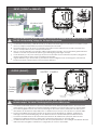
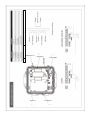
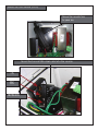
Installation and Operation Instructions
Before attempting to connect or operate this product, please
read these instructions completely.
PB24FM-SC
Standard Multi-Functional Power Box with EOF2N (Ethernet Over Fiber Converter)
PB24FM-SC...............Rugged cast aluminium power box with 220/115Vac input converting to 24Vac and 96W output power. Includes Ethernet over Fiber converter (EOF2N)
EOF2N
Moog Inc.
Sensor and Surveillance Systems
© 2013, Moog Inc. All Rights Reserved
3650 Woodhead Drive, Northbrook, IL. USA 60062
+1.847.498.0700 Fax: +1.847.498.1258 www.moogS3.com
81-IN5432 111913
IMPORTANT SAFEGUARDS
1
Read these instructions.
2
Keep these instructions.
3
Heed all warnings
4
Follow all instructions.
5
Do not use this apparatus near water.
6
Clean only with damp cloth.
7
CAUTION
RISK OF ELECTRIC SHOCK
DO NOT OPEN
Do not block any of the ventilation openings. Install in accordance with the
manufacturers instructions.
8
9
SAFETY PRECAUTIONS
Cable Runs- All cable runs must be within permissible distance.
CAUTION: TO REDUCE THE RISK OF
ELECTRIC SHOCK, DO NOT REMOVE
COVER ( OR BACK). NO USER- SERVICEABLE PARTS INSIDE. REFER SEVICING
TO QUALIFIED SERVICE PERSONNEL.
Mounting - This unit must be properly and securely mounted to a supporting
structure capable of sustaining the weight of the unit.
Accordingly:
a. This installation should be made by a qualified service person and should conform
to all local codes.
b. Care should be exercised to select suitable hardware to install the unit, taking into
account both the composition of the mounting surface and the weight of the unit.
10 Do not install near any heat sources such as radiators, heat registers, stoves, or other
apparatus ( including amplifiers) that produce heat.
11 Do not defeat the safety purpose of the polarized or grounding-type plug. A
polarized plug has two blades with one wider than the other. A grounding type
plug has two blades and a third grounding prong. The wide blade or the third
prong are provided for your safety. When the provided plug does not fit into your
outlet, consult an electrician for replacement of the obsolete outlet.
12 Protect the power cord from being walked on or pinched particularly at plugs,
convenience receptacles, and the point where they exit from the apparatus.
13 Only use attachment/ accessories specified by the manufacturer.
14 Use only with a cart, stand, tripod, bracket, or table specified by the manufacturer,
or sold with the apparatus. When a cart is used, use caution when moving the cart/
apparatus combination to avoid injury from tip-over.
15 Unplug this apparatus during lighting storms or when unused for long periods of time.
16 Refer all servicing to qualified service personnel. Servicing is required when the
apparatus has been damaged in any way, such as power-supply cord or plug is
damaged, liquid has been spilled of objects have fallen into the apparatus, the
The lightning flash with an arrowhead symbol,
within an equilateral triangle, is intended to
alert the user to the presence of non-insulated
“dangerous voltage” within the product’s
enclosure that may be of sufficient magnitude
to constitute a risk to persons.
Este símbolo se piensa para alertar al usuario a la presencia
del “voltaje peligroso no-aisIado” dentro del recinto de los
productos que puede ser un riesgo de choque eléctrico.
Ce symbole est prévu pour alerter I’utilisateur à la presence
“de la tension dangereuse” non-isolée dans la clôture de
produits qui peut être un risque de choc électrique.
Dieses Symbol soll den Benutzer zum Vorhandensein der
nicht-lsolier “Gefährdungsspannung” innerhalb der
Produkteinschließung alarmieren die eine Gefahr des
elektrischen Schlages sein kann.
Este símbolo é pretendido alertar o usuário à presença “di
tensão perigosa non-isolada” dentro do cerco dos produtos
que pode ser um risco de choque elétrico.
Questo simbolo è inteso per avvertire I’utente alla presenza
“di tensione pericolosa” non-isolata all’interno della
recinzione dei prodotti che può essere un rischio di scossa
elettrica.
apparatus has been exposed to rain or moisture, does not operate normally, or
has been dropped.
Be sure to periodically examine the unit and the supporting structure to make sure that the integrity
of the installation is intact. Failure to comply with the foregoing could result in the unit separating
from the support structure and falling, with resultant damages or injury to anyone or anything struck
by the falling unit.
UNPACKING
Unpack carefully. Electronic components can be
damaged if improperly handled or dropped. If an item
appears to have been damaged in shipment, replace
it properly in its carton and notify the shipper.
Be sure to save:
1 The shipping carton and packaging material.
They are the safest material in which to make future
shipments of the equipment.
2 These Installation and Operating Instructions.
SERVICE
If technical support or service is needed, contact us at
the following number:
TECHNICAL SUPPORT
AVAILABLE 24 HOURS
1 - 800 - 554 -1124
The exclamation point within an equilateral
triangle is intended to alert the user to
presence of important operating and
maintenance (servicing) instructions in the
literature accompanying the appliance.
Este símbolo del punto del exclamation se piensa para
alertar al usuario a la presencia de instrucciones importantes
en la literatura que acompaña la aplicación.
Ce symbole de point d’exclamation est prévu pour alerter
l’utilisateur à la presence des instructions importantes dans
la littérature accompagnant l’appareil.
Dieses Ausruf Punktsymbol soll den Benutzer zum
Vorhandensein de wichtigen Anweisungen in der Literatur
alarmieren, die das Gerät begleitet.
Este símbolo do ponto do exclamation é pretendido alertar o
usuário à presença de instruções importantes na literatura
que acompanha o dispositivo.
Questo simbolo del punto del exclamaton è inteso per
avvertire l’utente alla presenza delle istruzioni importanti nella
letteratura che accompagna l'apparecchio.
MADEIN
USA
BUY AMERICA COMPLIANT • COUNTRY OF ORIGIN U.S.A.
Product Warranty Registration
Register Your Products Online
www.moogS3.com/technical-support/product-registration
Moog values your patronage. We are solely committed to providing you with the highest quality products and
superior customer service. With 3-Year and 5-Year warranties (depending on the product purchased) we stand
behind every product we sell.
See full warranty details at www.moogS3.com/technical-support/warranty-plan/
:
• Simple and Trouble-Free RMA process
• Product / software updates
• Special promotions
• Eliminate the need to archive purchase documents such as receipts, purchase orders, etc.
Limited Warranty for Moog Products
Moog - Decatur Operations, subsequently referred to as “Manufacturer,” warrants these products to be free from defects in material or workmanship as follows:
PRODUCT CATEGORY
PARTS \ LABOR
All Enclosures and Electronics
Five (5) Years
Accessory Brackets
Five (5) Years
Controllers
Three (3) Years
Power Supplies / IR Illuminators
Three (3) Years
Poles / PolEvators / CamEvator
Three (3) Years
Warrior Series / Q-View
Three (3) Years
™
™
™
Three (3) Years 6 months if used in auto scan / tour operation
SView Series™
DeputyDome , NiteTrac , Igloo Dome, PurgeDome
Three (3) Years 6 months if used in auto scan / tour operation
EXO Series™ Dome and Fixed Camera Systems*
Three (3) Years 6 months if used in auto scan / tour operation
EXO Series™ GeminEye Visible and Thermal Camera Systems
One (1) Year
™
™
™
During the labor warranty period, to repair the Product, Purchaser will either return the defective product, freight prepaid, or deliver it to Manufacturer at Moog Decatur
Operations, 2525 Park Central Boulevard, Decatur, Georgia, 30035. The Product to be repaired is to be returned in either its original carton or a similar package affording
an equal degree of protection with a RMA # (Return Materials Authorization number) displayed on the outer box or packing slip. To obtain a RMA# you must contact our
Technical Support Team at 800.554.1124, extension 101. Manufacturer will return the repaired product freight prepaid to Purchaser. Manufacturer is not obligated to
provide Purchaser with a substitute unit during the warranty period or at any time. After the applicable warranty period, Purchaser must pay all labor and/or parts charges.
The limited warranty stated in these product instructions is subject to all of the following terms and conditions.
TERMS AND CONDITIONS
1. NOTIFICATION OF CLAIMS: WARRANTY SERVICE: If Purchaser believes that the Product is defective in material or workmanship, then written notice with an explanation
of the claim shall be given promptly by Purchaser to Manufacturer. All claims for warranty service must be made within the warranty period. If after investigation,
Manufacturer determines the reported problem was not covered by the warranty, Purchaser shall pay Manufacturer for the cost of investigating the problem at its then
prevailing per incident billable rate. No repair or replacement of any Product or part thereof shall extend the warranty period of the entire Product. The specific warranty on
the repaired part only shall be in effect for a period of ninety (90) days following the repair or replacement of that part or the remaining period of the Product parts warranty,
whichever is greater.
2. EXCLUSIVE REMEDY: ACCEPTANCE: Purchaser’s exclusive remedy and Manufacturer’s sole obligation is to supply (or pay for) all labor necessary to repair any Product
found to be defective within the warranty period and to supply, at no extra charge, new or rebuilt replacements for defective parts.
3. EXCEPTIONS TO LIMITED WARRANTY: Manufacturer shall have no liability or obligation to Purchaser with respect to any Product requiring service during the warranty
period which is subjected to any of the following: abuse, improper use, negligence, accident, or acts of God (i.e., hurricanes, earthquakes), modification, failure of the
end-user to follow the directions outlined in the product instructions, failure of the end-user to follow the maintenance procedures recommended by the International Security
Industry Organization, written in product instructions, or recommended in the service manual for the Product. Furthermore, Manufacturer shall have no liability where a
schedule is specified for regular replacement or maintenance or cleaning of certain parts (based on usage) and the end-user has failed to follow such schedule; attempted
repair by non-qualified personnel; operation of the Product outside of the published environmental and electrical parameters, or if such Product’s original identification
(trademark, serial number) markings have been defaced, altered, or removed. Manufacturer excludes from warranty coverage Products sold AS IS and/or WITH ALL FAULTS
and excludes used Products which have not been sold by Manufacturer to the Purchaser. All software and accompanying documentation furnished with, or as part of the
Product is furnished “AS IS” (i.e., without any warranty of any kind), except where expressly provided otherwise in any documentation or license agreement furnished with
the Product. ANY COST ASSOCIATED WITH REMOVAL OF DEFECTIVE PRODUCT AND INSTALLATION OF REPLACEMENT PRODUCT IS NOT INCLUDED IN THIS WARRANTY.
4. PROOF OF PURCHASE: The Purchaser’s dated bill of sale must be retained as evidence of the date of purchase and to establish warranty eligibility.
DISCLAIMER OF WARRANTY
EXCEPT FOR THE FOREGOING WARRANTIES, MANUFACTURER HEREBY DISCLAIMS AND EXCLUDES ALL OTHER WARRANTIES, EXPRESS OR IMPLIED, INCLUDING, BUT
NOT LIMITED TO ANY AND/OR ALL IMPLIED WARRANTIES OF MERCHANTABILITY, FITNESS FOR A PARTICULAR PURPOSE AND/OR ANY WARRANTY WITH REGARD TO ANY
CLAIM OF INFRINGEMENT THAT MAY BE PROVIDED IN SECTION 2-312(3) OF THE UNIFORM COMMERCIAL CODE AND/OR IN ANY OTHER COMPARABLE STATE STATUTE.
MANUFACTURER HEREBY DISCLAIMS ANY REPRESENTATIONS OR WARRANTY THAT THE PRODUCT IS COMPATIBLE WITH ANY COMBINATION OF NON-MANUFACTURER
PRODUCTS OR NON-MANUFACTURER RECOMMENDED PRODUCTS PURCHASER MAY CHOOSE TO CONNECT TO THE PRODUCT.
LIMITATION OF LIABILITY
THE LIABILITY OF Manufacturer, IF ANY, AND PURCHASER’S SOLE AND EXCLUSIVE REMEDY FOR DAMAGES FOR ANY CLAIM OF ANY KIND WHATSOEVER, REGARDLESS
OF THE LEGAL THEORY AND WHETHER ARISING IN TORT OR CONTRACT, SHALL NOT BE GREATER THAN THE ACTUAL PURCHASE PRICE OF THE PRODUCT WITH RESPECT
TO WHICH SUCH CLAIM IS MADE. IN NO EVENT SHALL MANUFACTURER BE LIABLE TO PURCHASER FOR ANY SPECIAL, INDIRECT, INCIDENTAL, OR CONSEQUENTIAL
DAMAGES OF ANY KIND INCLUDING, BUT NOT LIMITED TO, COMPENSATION, REPLACEMENT LABOR COSTS, REIMBURSEMENT, OR DAMAGES ON ACCOUNT OF THE LOSS
OF PRESENT OR PROSPECTIVE PROFITS OR FOR ANY OTHER REASON WHATSOEVER.
* NOTE
Moog will repair or replace, at its option, any equipment which is damaged by transient voltage surge/spike or lightning strike (an “Occurrence”), while properly connected
to wired AC power line with protective ground. Any repair or modification of the equipment done by someone other than Moog voids the warranty.
Electrical Specifications
PB24FM-SC
English
Input Power: 110 VAC/220VAC 1A/.5A Power Consumption: 1Amp
(120 Watts) at 120 VAC Power Output: 96 VA at 24 VAC 52 Watts
Heater/Blower 32 Watts Camera Power
An all pole main switch with a contact of at least 3mm in each
pole shall be incorporated in the electrical installation of the
building.
Tools Required: .150” Flathead Screwdriver 7/16 Wrench or Socket
9/16 Wrench or Socket
Español
Energía De Entrada: 110 Consumo De Energía de VAC/220VAC
1A/.5A: 1Amp (120 vatios) en 120 VAC de salida de energía: VA
96 en 24 VAC 52 vatios de Heater/Blower 32 vatios de energía de
la cámara fotográfica
Todo el interruptor principal del poste con un contacto de por lo
menos 3m m en cada poste será incorporado en la instalación
eléctrica del edificio.
Herramientas Requeridas: destornillador de cabeza llana del
150"7/16 llave de la llave o del zócalo 9/16 o zócalo
Français
Puissance D'entrée : 110 Puissance D'Énergie de VAC/220VAC
1A/.5A : 1Amp (120 watts) à 120 VCA de rendement de
puissance : VA 96 à 24 VCA 52 watts de Heater/Blower 32 watts
de puissance d'appareil-photo
Un tout le commutateur principal de poteau avec un contact au
moins de 3mm dans chaque poteau sera incorporé dans
l'installation électrique du bâtiment.
Outils Requis : tournevis à tête plate de 150"7/16 clé de clé ou de
douille 9/16 ou douille
Deutsch
Zugeführte Energie: 110 VAC/220VAC 1A/.5A Leistungsaufnahme:
1Amp (120 Watt) bei 120 VAC Abgabeleistung: VA 96 bei 24 VAC
52 Watt Heater/Blower 32 Watt Kamera-Energie
Ein aller Pfostenhauptschalter mit einem Kontakt von 3mm
mindestens in jedem Pfosten wird in der elektrischen Installation
des Gebäudes enthalten.
Werkzeuge Erforderten: 150"Flachkopfschraubenzieher 7/16
Schlüssel-oder Einfaßung 9/16 Schlüssel oder Einfaßung
Portuguese
Poder De Entrada: 110 Consumo De Potência de VAC/220VAC
1A/.5A: 1Amp (120 watts) em 120 VAC de saída de poder: VA 96
em 24 VAC 52 watts de Heater/Blower 32 watts de poder da
câmera
Todo o interruptor principal do pólo com um contato ao menos
de 3mm em cada pólo será incorporado na instalação elétrica
do edifício.
As Ferramentas Requereram: chave de fenda flathead do
150"7/16 de chave da chave ou do soquete 9/16 ou soquete
Italiano
Alimentazione in ingresso Di Entrata: 110 Assorbimento di corrente
Di energia di VAC/220VAC 1A/.5A: 1Amp (120 watt) a 120 VCA di
uscita di alimentazione: VA 96 a 24 VCA 52 watt di Heater/Blower
32 watt di alimentazione della macchina fotografica
Tutto l'interruttore principale del palo con un contatto almeno di
3mm in ogni palo sarà compreso nell'installazione elettrica della
costruzione.
Attrezzi Richiesti: cacciavite a testa piatta del 150"7/16 di chiave
dallo zoccolo o dalla chiave 9/16 o zoccolo
Contents of Box
1
2
Wall Mounting: Attach unit securely with (4)
3/8” or 8mm hardware (not supplied).
• La pared que monta la caja de la energía es posible,
pero el hardware no es incluido.
• Le mur montant la boîte de puissance est possible,
mais le matériel n'est pas inclus.
• Die Wand, die den Energie Kasten anbringt, ist
möglich, aber die Kleinteile sind nicht enthalten.
• A parede que monta a caixa do poder é possível,
mas a ferragem não é incluída.
• La parete che monta la scatola di alimentazione è
possibile, ma i fissaggi non sono inclusi.
3
Wall Mount
Gasket
The power box may be pole mounted with
the pole support clips.
• Ésta es la plantilla del montaje para la caja de la
energía.
• C'est le calibre de support pour la boîte de puissance.
• Dieses ist die Montageschablone für den Energie
Kasten.
• Este é o molde da montagem para a caixa do poder.
• Ciò è la mascherina del montaggio per la scatola di
alimentazione.
4
3/8” Bolts
Washer
3/8” Nut and Lockwashers
Conduit Fitting
The wall mount bracket must be attached
using the gasket as shown.
This is the assembled unit with the housing
and conduit.
• El soporte del montaje de la pared se debe unir
usando la junta según lo demostrado.
• La parenthèse de bâti de mur doit être jointe utilisant
la garniture comme montrée.
• Der Wandeinfassung Haltewinkel muß mit der Dichtung angebracht werden, wie gezeigt worden.
• O suporte da montagem da parede deve ser unido
usando a gaxeta como mostrado.
• La staffa del supporto della parete deve essere
fissata per mezzo della guarnizione come indicata.
• El soporte del montaje de la pared se debe unir
usando la junta según lo demostrado.
• La parenthèse de bâti de mur doit être jointe utilisant
la garniture comme montrée.
• Der Wandeinfassung Haltewinkel muß mit der
Dichtung angebracht werden, wie gezeigt worden.
• O suporte da montagem da parede deve ser unido
usando a gaxeta como mostrado.
• La staffa del supporto della parete deve essere fissata
per mezzo della guarnizione come indicata.
INPUT: (120VAC or 240VAC)
220-240VAC INPUT
110-120VAC INPUT
240Vac
120Vac Input
Input
Main
Switch
Line (L) and Neutral (N) wires should be connected as marked on the board and plugged
into the corresponding voltage for the input single phase.
Los alambres de la línea (l) y del hilo neutro (n) se deben conectar según lo marcados en el tablero y tapados en el voltaje correspondiente para la monofásico de la entrada.
Des fils de la ligne (l) et du neutre (n) devraient être reliés comme marqué sur le conseil et branché à la
tension correspondante pour le monophasé d'entrée.
Linie (L) und des Neutralen (N) Leitungen sollten angeschlossen werden, wie auf dem Brett gekennzeichnet
worden und in die entsprechende Spannung für das Eingang einphasige verstopft.
Os fios da linha (L) e do ponto morto (N) devem ser conectados como marcados na placa e plugged na
tensão correspondente para a fase monofásica da entrada.
I legare della linea (l) e del neutrale (n) dovrebbero essere collegati come contrassegnato sul bordo ed
inserito la tensione corrispondente per la monofase dell'input.
OUTPUT: (24VAC)
HEATERS CAMERA
Connect
Housing
Power
24Vac Power
To Housing
Optional 24Vac
Output
Main
Switch
Internal resettable fuses are supplied for the main 24VAC output lines. Do not connect heaters
to camera output. The 30334 is not designed for 3 phase or 208V systems.
Los fusibles restaurables internos se proveen para las líneas de salida principales 24VAC. No conecte los
calentadores con la salida de la cámara fotográfica. El 30334 no se diseña para 3 fases o sistemas 208V.
Des fusibles réglables internes sont fournis pour les lignes de la sortie 24VAC principales. Ne reliez pas les
réchauffeurs au rendement d'appareil-photo. Le 30334 n'est pas conçu pour 3 phases ou systèmes 208V.
Interne rückstellbare Sicherungen werden für die Haupt-24VAC Ertragskurven geliefert. Schließen Sie
Heizungen nicht an Kameraausgang an. Das 30334 ist nicht für 3 Phase oder Systeme 208V bestimmt.
Os fusíveis resettable internos são fornecidos para as linhas de saída 24VAC principais. Não conecte
calefatores à saída da câmera. O 30334 não é projetado para 3 fases ou sistemas 208V.
I fusibili resettable interni sono forniti per le linee di uscita principali 24VAC. Non colleghi i riscaldatori all'uscita
della macchina fotografica. Il 30334 non è progettato per 3 fase o sistemi 208V.
Ethernet over Fiber Converter
EOF2N
RP70TRAN11
RP76PCBPB01
N/S
RP70TRAN11
RP4OHGPB1000
RPVL2781
RP96GK2680
Ethernet Over Fiber Converter (EOF2N)
Remove fiber converter from
the power box.
Connect fiber lines and RJ45 network cable to the fiber converter.
TX
RX
Network
Electrostatic Discharge (ESD)
Always observe the following ESD precautions when installing or handing the EOF2N media converter:
• Do not remove the converter from its protective packaging until you are ready to install it.
• Wear an ESD wrist grounding strap before handling any module or component. If you do not have a wrist strap,
maintain grounded connection with the system unit throughout any procedure requiring ESD protection.
CAUTION:
Integrated circuits and fiber optic components are extremely susceptible to electrostatic discharge damage. Failure to
observe this caution could result in damage to these components.
WARNING:
If the media converter is an IEEE802.3-2005 Powered Device (PD) capable of receiving power via the Media Dependent
Interface (MDI) leads, the power source, connector, and cables attached to the barrel power connector must meet the isolation
requirement specified in IEEE802.3-2005.
Copper and Fiber ports
The illustration below shows the front panel of the EOF2N media converters.
TX-Link/Act LED
FX-Link /Act LED
TX
RX
Copper Port
Fiber Port
Power ON LED
Connect the fiber cable
Full duplex (always ON) is on the fiber side only; therefore, the 512-Bit Rule does not apply. The cable lengths are constrained by
the cable requirement.
1. Locate or build IEEE 803.2™ compliant 100Base-FX fiber cable with male, two-stranded TX to RX connectors installed at
both ends.
2. Connect the fiber cable to the EOF2N media converters as follows:
• Connect the male TX cable connector to the female TX port.
• Connect the male RX cable connector to the female RX port.
3. Connect the fiber cable to the other device (another media converter, hub, etc.) as follows:
• Connect the male TX cable connector to the female RX port.
• Connect the male RX cable connector to the female TX port.
Connect the fiber cable to
the media converters as
shown.
Connect the fiber cable
to other device (media
converter, hub, etc.) as
shown
RX
RX
TX
TX
Connect the twisted-pair copper cable
The EOF2N allows either MDI (straight-through) or MDI-X (crossover) cable connections to be configured automatically, according to network
conditions.
• If half-duplex mode is used, refer to the 512-Bit Rule.
• If full-duplex mode is used, the 512-Bit Rule does not apply. The cable lengths are constrained by the cable requirements.
1. Locate or build IEEE 803.2™ compliant 10Base-T or 100Base-TX cables, with RJ-45 connectors installed at both ends.
2. Connect the RJ-45 connector at one end of the cable to the RJ-45 port on the EOF2N media converter.
3. Connect the RJ-45 connector at the other end of the cable to the RJ-45 port on the other device (switch, workstation, etc.).
RJ-45 port
on the media
converter
RJ-45 port
on the other device
(switch, work station, etc.)
Status LEDs
LED discriptions are as follows:
Use the LEDs to monitor the status of the media converter.
TX-Link/Act LED
FX-Link/Act LED
Green
FX-Link/Act LED RX
TX
ON = Link (fiber)
Flashing = Activity
TX -Link/Act LED
Green
ON = Link
Flashing = Activity
Power LED
Fiber
Port
Power ON LED
Green
ON
= Connected to power
Front Panel
Product features
Congestion reduction
The EOF2N media converter do not forward collision signals or error packets from one collision domain to another, resulting in improvements in baseline network performance. In
addition, the media converter filters packets destined for local devices, which reduces network congestion also.
Auto-Negotiation
The Auto-Negotiation feature is ON permanently for the EOF2N media converters. Auto-Negotiation allows the media converter to configure itself automatically to achieve the
best possible mode of operation over a link. It broadcasts speed (10 Mb/s or 100 Mb/s) and duplex capabilities (full or half) to the other device and negotiates the best mode of
operation. Auto-Negotiation allows quick and easy installation because the optimal link is established automatically.
In a scenario where an auto-negotiation device is linked to a non-negotiating device, the negotiating device via parallel detection recognizes the speed of that second device then
establishes the best operating speed (10Mbs or 100Mbs) at half-duplex.
MDI or MDI-X
The EOF2N utilizes either straight-through (MDI) or crossover (MDI-X) copper cables when connecting to 10Base-T or 100Base-TX devices. the EOF2N determines the
characteristics of the connection and automatically configures the device to link up, regardless of the copper cable configuration, MDI or MDI-X.
Link Pass-Through
The Link Pass-Through feature (illustrated below) allows the media converter to monitor both the fiber and copper RX (receive) port for loss of signal. In the event of an RX signal
loss (1), the media converter will automatically disable the TX (transmit) signal (2), thus “passing through” the link loss (3). The far-end device is automatically notified of the link
loss (4), which prevents the loss of valuable data unknowingly transmitted over an invalid link.
media converter A
disables the fiber TX link
media converter B
loses the fiber RX link
2
3
Media
Converter A
Near-End
Device
Media
Converter B
1
Far-End
Device
4
original fault
on the copper link
media converter B
disables the copper link
Note: In the link pass-through devices (EOF2N) both copper and fiber cables must be installed before the LEDs will light.
Auto-Negotiation, AutoCross, Link Pass-Through, Far End Fault
Media ConverterAuto-NegotiationAutoCrossLPTFEF
EOF2N
Yes
Yes
No
Yes
Product features
Automatic link restoration
The media converter will automatically re-establish the link when connected to switches if the link is lost, even with Auto-Negotiation and Link
Pass-through ( both directions) enabled.
Full-Duplex flow control
In a full-duplex network, the maximum cable lengths are determined by the type of cables used for EOF2N cable specifications.
The 512-Bit Rule does not apply in a full-duplex network.
Note:
Full duplex is ON permanently for the fiber port only.
Half-Duplex flow control (512-Bit Rule)
In a half-duplex network, the maximum cable lengths are determined by the round-trip dely limitations of each Fast Ethernet collision domain.
( A collision domain is the longest path between any two terminal devices; e.g., a terminal, switch, or router.)
The 512-Bit Rule determines the maximum length of cable permitted by calculating the round-trip delay in bit-times (BT) of a particular
collision domain. If the result is less than or equal to 512 BT, the path is good.
Flow Control
The process of adjusting the flow of data from one device to another ensures that the receiving decive can handle all of the incoming data.
This is particularly important where the sending device is capable of transmitting data much faster than the receiving device can accept it.
Distance extension
The EOF2N media converters cam segment one (1) 10Base-T copper Ethernet and/or 100Base-TX copper Fast Ethernet, and one (1)
100Base-FX fiber Fast Ethernet collision domain:
In a half-duplex Ethernet or Fast Ethernet environment, the EOF2N media converters extend network distances by segmenting collision
domains so that the 512-Bit Rule applies separately to each collision domain.
In a full-duplex Ethernet or Fast environment, the EOF2N media converters extend network distances to the physical cable limitations imposed
by the selected twisted-pair copper fiber cables.
Rate conversion
The EOF2N media converters allow connection of 10Mb/s terminal devices on a 10Base-T legacy Ethernet copper network to 100Mb/s
terminal devices on a 100Base-TX Fast Ethernet copper network and/or to 100Mb/s terminal devices on a 100Base-FX Fast Ethernet fiber
network.
Far-End Fault (always ON)
When a fault occurs on an incoming fiber link (1), the media converter transmits a Far-End Fault signal on the outgoing fiber link (2). In
addition the Far-End Fault signal also activates the Link Pass-Through, which, in turn, disables the link on the copper portion of the network (3)
and (4). original fault
on the fiber link
1
Near-End
Device
Media
Converter A
4
media converter A
disables the copper link
Media
Converter B
2
Far-End Fault
signal is sent
Far-End
Device
3
media converter B
disables the copper link
Cable Specifications
The physical characteristics must meet or exceed IEEE 802.3™ specifications.
Fiber cable
Bite Error Rate:<10-9
single mode fiber (recommended):
9 µm
Multimode fiber (recommended):
62.5/125 µm
Multimode fiber (optional):
100/140, 85/140, 50/125 µm
EOF2N
EOF2N1300 nm multimode
Fiber-Optic Transmitter Power:
min: -19.0 dBm max: - 14.0 dBm
Fiber-Optic Receiver Sensitivity:
min: - 30.0 dBm max: - 14.0 dBm
The fiber optic transmitters on this device meet Class I Laser safety requirements per IEC-825/CDRH standards and comply with 21
CFR1040.10 and 21CFR1040.11.
Copper cable
Category 3:
( Minimum requirement for 10 Mb/s operation )
Gauge24 to 22 AWG
Attenuation11.5 dB/100m @ 5-10 MHz
Maximum Cable Distance100 meters
Category 5:
( Minimum requirement for 100 Mb/s operation )
Gauge24 to 22 AWG
Attenuation22.0 dB /100m @ 100 MHz
Maximum Cable Distance100 meters
• Straight-through or crossover twisted-pair cable may be used.
• Shielded (STP) or unshielded (UTP) twisted-pair cable may be used.
• Pins 1&2 and 3&6 are the two active pairs in an Ethernet network.
• Use only dedicated wire pairs for the active pins:
(e.g., blue/white & white/blue, orange/white & white/orange, etc.)
• Do not use flat or silver satin wire.
Straight-Through
Crossover Cable
Twisted Pair #1
Twisted Pair #1
Twisted Pair #2
Twisted Pair #2