1
Installation and Operation Instructions
Before attempting to connect or operate this product, please
read these instructions completely.
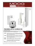
VLRM58 and VLRM24
MIMO Wireless Solutions
VLRM58........Wireless 5.8GHz MIMO access point, 120Vac input (Power supply) 24Vdc PoE
VLRM24.........Wireless 2.4GHz MIMO access point, 120Vac input (Power supply) 24Vdc PoE
VLRM58
5.8 Receiver
VLRM24
2.4 Receiver
Moog Inc.
Sensor and Surveillance Systems
© 2014, Moog Inc. All Rights Reserved
3650 Woodhead Drive Northbrook, IL. USA 60062
+1.847.498.0700 Fax: +1.847.498.1258 www.moogS3.com
81-IN5468 102814
IMPORTANT SAFEGUARDS
1
Read these instructions.
2
Keep these instructions.
3
Heed all warnings
4
Follow all instructions.
5
Do not use this apparatus near water.
6
Clean only with damp cloth.
7
SAFETY PRECAUTIONS
CAUTION
RISK OF ELECTRIC SHOCK
DO NOT OPEN
CAUTION: TO REDUCE THE RISK OF
ELECTRIC SHOCK, DO NOT REMOVE
COVER ( OR BACK). NO USER- SERVICEABLE PARTS INSIDE. REFER SEVICING
TO QUALIFIED SERVICE PERSONNEL.
Do not block any of the ventilation openings. Install in accordance with the
manufacturers instructions.
8
9
Cable Runs- All cable runs must be within permissible distance.
Mounting - This unit must be properly and securely mounted to a supporting
structure capable of sustaining the weight of the unit.
Accordingly:
a. The installation should be made by a qualified installer.
b. The installation should be in compliance with local codes.
c. Care should be exercised to select suitable hardware to install the unit, taking into
account both the composition of the mounting surface and the weight of the unit.
10 Do not install near any heat sources such as radiators, heat registers, stoves, or other
apparatus ( including amplifiers) that produce heat.
11 Do not defeat the safety purpose of the polarized or grounding-type plug. A
polarized plug has two blades with one wider than the other. A grounding type
plug has two blades and a third grounding prong. The wide blade or the third
prong are provided for your safety. When the provided plug does not fit into your
outlet, consult an electrician for replacement of the obsolete outlet.
12 Protect the power cord from being walked on or pinched particularly
at plugs,
convenience receptacles, and the point where they exit from the apparatus.
13 Only use attachment/ accessories specified by the manufacturer.
14 Use only with a cart, stand, tripod, bracket, or table specified by the manufacturer,
or sold with the apparatus. When a cart is used, use caution when moving the cart/
apparatus combination to avoid injury from tip-over.
15 Unplug this apparatus during lighting storms or when unused for long periods of time.
16 Refer all servicing to qualified service personnel. Servicing is required when the
apparatus has been damaged in any way, such as power-supply cord or plug is
damaged, liquid has been spilled of objects have fallen into the apparatus, the
The lightning flash with an arrowhead symbol,
within an equilateral triangle, is intended to
alert the user to the presence of non-insulated
“dangerous voltage” within the product’s
enclosure that may be of sufficient magnitude
to constitute a risk to persons.
Este símbolo se piensa para alertar al usuario a la presencia
del “voltaje peligroso no-aisIado” dentro del recinto de los
productos que puede ser un riesgo de choque eléctrico.
Ce symbole est prévu pour alerter I’utilisateur à la presence
“de la tension dangereuse” non-isolée dans la clôture de
produits qui peut être un risque de choc électrique.
Dieses Symbol soll den Benutzer zum Vorhandensein der
nicht-lsolier “Gefährdungsspannung” innerhalb der
Produkteinschließung alarmieren die eine Gefahr des
elektrischen Schlages sein kann.
Este símbolo é pretendido alertar o usuário à presença “di
tensão perigosa non-isolada” dentro do cerco dos produtos
que pode ser um risco de choque elétrico.
Questo simbolo è inteso per avvertire I’utente alla presenza
“di tensione pericolosa” non-isolata all’interno della
recinzione dei prodotti che può essere un rischio di scossa
elettrica.
apparatus has been exposed to rain or moisture, does not operate normally, or
has been dropped.
Be sure to periodically examine the unit and the supporting structure to make sure that the integrity
of the installation is intact. Failure to comply with the foregoing could result in the unit separating
from the support structure and falling, with resultant damages or injury to anyone or anything struck
by the falling unit.
UNPACKING
Unpack carefully. Electronic components can be
damaged if improperly handled or dropped. If an item
appears to have been damaged in shipment, replace
it properly in its carton and notify the shipper.
Be sure to save:
1 The shipping carton and packaging material.
They are the safest material in which to make future
shipments of the equipment.
2 These Installation and Operating Instructions.
SERVICE
If technical support or service is needed, contact us at
the following number:
TECHNICAL SUPPORT
AVAILABLE 24 HOURS
1 - 800 - 554 -1124
The exclamation point within an equilateral
triangle is intended to alert the user to
presence of important operating and
maintenance (servicing) instructions in the
literature accompanying the appliance.
Este símbolo del punto del exclamation se piensa para
alertar al usuario a la presencia de instrucciones importantes
en la literatura que acompaña la aplicación.
Ce symbole de point d’exclamation est prévu pour alerter
l’utilisateur à la presence des instructions importantes dans
la littérature accompagnant l’appareil.
Dieses Ausruf Punktsymbol soll den Benutzer zum
Vorhandensein de wichtigen Anweisungen in der Literatur
alarmieren, die das Gerät begleitet.
Este símbolo do ponto do exclamation é pretendido alertar o
usuário à presença de instruções importantes na literatura
que acompanha o dispositivo.
Questo simbolo del punto del exclamaton è inteso per
avvertire l’utente alla presenza delle istruzioni importanti nella
letteratura che accompagna l'apparecchio.
MADEIN
USA
BUY AMERICA COMPLIANT • COUNTRY OF ORIGIN U.S.A.
Product Warranty Registration
Register Your Products Online
www.moogS3.com/technical-support/product-registration
Moog values your patronage. We are solely committed to providing you with the highest quality products and
superior customer service. With 3-Year and 5-Year warranties (depending on the product purchased) we stand
behind every product we sell.
See full warranty details at www.moogS3.com/technical-support/warranty-plan/
:
• Simple and Trouble-Free RMA process
• Product / software updates
• Special promotions
• Eliminate the need to archive purchase documents such as receipts, purchase orders, etc.
Limited Warranty for Moog Products
Moog - Decatur Operations, subsequently referred to as “Manufacturer,” warrants these products to be free from defects in material or workmanship as follows:
PRODUCT CATEGORY
PARTS \ LABOR
All Enclosures and Electronics
Five (5) Years
Accessory Brackets
Five (5) Years
Controllers
Three (3) Years
Power Supplies / IR Illuminators
Three (3) Years
Poles / PolEvators / CamEvator
Three (3) Years
Warrior Series™ / Q-View™
Three (3) Years
SView Series
Three (3) Years 6 months if used in auto scan / tour operation
DeputyDome™, NiteTrac™, Igloo Dome, PurgeDome™
Three (3) Years 6 months if used in auto scan / tour operation
EXO Series Dome and Fixed Camera Systems*
Three (3) Years 6 months if used in auto scan / tour operation
EXO Series GeminEye Visible and Thermal Camera Systems
One (1) Year
™
™
™
™
During the labor warranty period, to repair the Product, Purchaser will either return the defective product, freight prepaid, or deliver it to Manufacturer at Moog Decatur
Operations, 2525 Park Central Boulevard, Decatur, Georgia, 30035. The Product to be repaired is to be returned in either its original carton or a similar package affording
an equal degree of protection with a RMA # (Return Materials Authorization number) displayed on the outer box or packing slip. To obtain a RMA# you must contact our
Technical Support Team at 800.554.1124, extension 101. Manufacturer will return the repaired product freight prepaid to Purchaser. Manufacturer is not obligated to
provide Purchaser with a substitute unit during the warranty period or at any time. After the applicable warranty period, Purchaser must pay all labor and/or parts charges.
The limited warranty stated in these product instructions is subject to all of the following terms and conditions.
TERMS AND CONDITIONS
1. NOTIFICATION OF CLAIMS: WARRANTY SERVICE: If Purchaser believes that the Product is defective in material or workmanship, then written notice with an explanation
of the claim shall be given promptly by Purchaser to Manufacturer. All claims for warranty service must be made within the warranty period. If after investigation,
Manufacturer determines the reported problem was not covered by the warranty, Purchaser shall pay Manufacturer for the cost of investigating the problem at its then
prevailing per incident billable rate. No repair or replacement of any Product or part thereof shall extend the warranty period of the entire Product. The specific warranty on
the repaired part only shall be in effect for a period of ninety (90) days following the repair or replacement of that part or the remaining period of the Product parts warranty,
whichever is greater.
2. EXCLUSIVE REMEDY: ACCEPTANCE: Purchaser’s exclusive remedy and Manufacturer’s sole obligation is to supply (or pay for) all labor necessary to repair any Product
found to be defective within the warranty period and to supply, at no extra charge, new or rebuilt replacements for defective parts.
3. EXCEPTIONS TO LIMITED WARRANTY: Manufacturer shall have no liability or obligation to Purchaser with respect to any Product requiring service during the warranty
period which is subjected to any of the following: abuse, improper use, negligence, accident, or acts of God (i.e., hurricanes, earthquakes), modification, failure of the
end-user to follow the directions outlined in the product instructions, failure of the end-user to follow the maintenance procedures recommended by the International Security
Industry Organization, written in product instructions, or recommended in the service manual for the Product. Furthermore, Manufacturer shall have no liability where a
schedule is specified for regular replacement or maintenance or cleaning of certain parts (based on usage) and the end-user has failed to follow such schedule; attempted
repair by non-qualified personnel; operation of the Product outside of the published environmental and electrical parameters, or if such Product’s original identification
(trademark, serial number) markings have been defaced, altered, or removed. Manufacturer excludes from warranty coverage Products sold AS IS and/or WITH ALL FAULTS
and excludes used Products which have not been sold by Manufacturer to the Purchaser. All software and accompanying documentation furnished with, or as part of the
Product is furnished “AS IS” (i.e., without any warranty of any kind), except where expressly provided otherwise in any documentation or license agreement furnished with
the Product. ANY COST ASSOCIATED WITH REMOVAL OF DEFECTIVE PRODUCT AND INSTALLATION OF REPLACEMENT PRODUCT IS NOT INCLUDED IN THIS WARRANTY.
4. PROOF OF PURCHASE: The Purchaser’s dated bill of sale must be retained as evidence of the date of purchase and to establish warranty eligibility.
DISCLAIMER OF WARRANTY
EXCEPT FOR THE FOREGOING WARRANTIES, MANUFACTURER HEREBY DISCLAIMS AND EXCLUDES ALL OTHER WARRANTIES, EXPRESS OR IMPLIED, INCLUDING, BUT
NOT LIMITED TO ANY AND/OR ALL IMPLIED WARRANTIES OF MERCHANTABILITY, FITNESS FOR A PARTICULAR PURPOSE AND/OR ANY WARRANTY WITH REGARD TO ANY
CLAIM OF INFRINGEMENT THAT MAY BE PROVIDED IN SECTION 2-312(3) OF THE UNIFORM COMMERCIAL CODE AND/OR IN ANY OTHER COMPARABLE STATE STATUTE.
MANUFACTURER HEREBY DISCLAIMS ANY REPRESENTATIONS OR WARRANTY THAT THE PRODUCT IS COMPATIBLE WITH ANY COMBINATION OF NON-MANUFACTURER
PRODUCTS OR NON-MANUFACTURER RECOMMENDED PRODUCTS PURCHASER MAY CHOOSE TO CONNECT TO THE PRODUCT.
LIMITATION OF LIABILITY
THE LIABILITY OF Manufacturer, IF ANY, AND PURCHASER’S SOLE AND EXCLUSIVE REMEDY FOR DAMAGES FOR ANY CLAIM OF ANY KIND WHATSOEVER, REGARDLESS
OF THE LEGAL THEORY AND WHETHER ARISING IN TORT OR CONTRACT, SHALL NOT BE GREATER THAN THE ACTUAL PURCHASE PRICE OF THE PRODUCT WITH RESPECT
TO WHICH SUCH CLAIM IS MADE. IN NO EVENT SHALL MANUFACTURER BE LIABLE TO PURCHASER FOR ANY SPECIAL, INDIRECT, INCIDENTAL, OR CONSEQUENTIAL
DAMAGES OF ANY KIND INCLUDING, BUT NOT LIMITED TO, COMPENSATION, REPLACEMENT LABOR COSTS, REIMBURSEMENT, OR DAMAGES ON ACCOUNT OF THE LOSS
OF PRESENT OR PROSPECTIVE PROFITS OR FOR ANY OTHER REASON WHATSOEVER.
* NOTE
Moog will repair or replace, at its option, any equipment which is damaged by transient voltage surge/spike or lightning strike (an “Occurrence”), while properly connected
to wired AC power line with protective ground. Any repair or modification of the equipment done by someone other than Moog voids the warranty.
Form 500-911 081913
Electrical Specifications
English
Contents of Box
Power Supply: 24Vdc, .5A POE Supply Included
Max Power Consumption: 6.5 Watts (2.4GHz) 8 Watts (5.8GHz)
Power Method: Passive Power over Ethernet (pairs 4,5+; 7,8 return)
VLRM24
An all pole main switch with a contact of at least 3mm in each
pole shall be incorporated in the electrical installation of the
building.
Tools Required: .150” Flathead Screwdriver 7/16 Wrench or Socket
9/16 Wrench or Socket
Español
Fuente de alimentación: 24Vdc, fuente de .5A POE incluida
Consumo de energía máximo: 6.5 vatios (2.4GHz) 8 vatios (5.8GHz)
Método de la energía: Energía pasiva sobre Ethernet
(pares 4.5+; vuelta 7.8)
Todo el interruptor principal del poste con un contacto de por lo
menos 3m m en cada poste será incorporado en la instalación
eléctrica del edificio.
Herramientas Requeridas: destornillador de cabeza llana del
150"7/16 llave de la llave o del zócalo 9/16 o zócalo
Français
Alimentation d'énergie: 24Vdc, approvisionnement de .5A POE
inclus Puissance maximum: 6.5 watts (2.4GHz) 8 watts (5.8GHz)
Méthode de puissance: Puissance passive au-dessus d'Ethernet
(paires 4.5+ ; retour 7.8)
Un tout le commutateur principal de poteau avec un contact au
moins de 3mm dans chaque poteau sera incorporé dans
l'installation électrique du bâtiment.
Outils Requis : tournevis à tête plate de 150"7/16 clé de clé ou de
douille 9/16 ou douille
Deutsch
Spg.Versorgungsteil: 24Vdc, .5A POE Versorgungsmaterial schloß
ein Maximale Leistungsaufnahme: 6.5 Watt (2.4GHz) 8 Watt
(5.8GHz) Energien-Methode: Passive Energie über Ethernet
(Paare 4.5+; Rückkehr 7.8)
Ein aller Pfostenhauptschalter mit einem Kontakt von 3mm
mindestens in jedem Pfosten wird in der elektrischen Installation
des Gebäudes enthalten.
Werkzeuge Erforderten: 150"Flachkopfschraubenzieher 7/16
Schlüssel-oder Einfaßung 9/16 Schlüssel oder Einfaßung
Portuguese
VLRM58
Fonte de alimentação: 24Vdc, fonte do ponto de entrada de
.5A incluída.
Consumo de potência máximo: 6.5 watts (2.4GHz) 8 watts (5.8GHz)
Método do poder: Poder passivo sobre o Ethernet
(pares 4.5+; retorno 7.8)
Todo o interruptor principal do pólo com um contato ao menos
de 3mm em cada pólo será incorporado na instalação elétrica
do edifício.
As Ferramentas Requereram: chave de fenda flathead do
150"7/16 de chave da chave ou do soquete 9/16 ou soquete
Italiano
Alimentazione elettrica: 24Vdc, rifornimento di .5A POE incluso
Assorbimento di corrente di energia massimo: 6.5 watt (2.4GHz)
8 watt (5.8GHz)
Metodo di potere: Potere passivo sopra Ethernet
(accoppiamenti 4.5+; ritorno 7.8)
Tutto l'interruttore principale del palo con un contatto almeno di
3mm in ogni palo sarà compreso nell'installazione elettrica della
costruzione.
Attrezzi Richiesti: cacciavite a testa piatta del 150"7/16 di chiave
dallo zoccolo o dalla chiave 9/16 o zoccolo
GENERAL INSTRUCTIONS (Mechanical):
Tools Required (minimum)
.150” Flat head Screwdriver
7/16” Wrench or Socket
9/16” Wrench or Socket
Wireless Cabling Best Practice
CAUTION:
MUST USE SHIELDED CABLE / CONNECTOR
Product Description
The VLRM24/58 is a Wi-Fi Station with WPA and WPA2 supplicant support. It is specially designed to act as a
Transparent Wireless Bridge that associates to a service provider and authenticates using 802.1x, if required, on start up.
Product Features
•
10/100 Ethernet interface with
•
High Power outdoor access point and adjustable auto-crossover detectiontransmit power
•
WPA/WPA2- Personal and WPA/WPA2
•
Specially designed for transparent
- Enterprise supportInternet access
1
When using directional antennae, the AP unit and
client should be aimed toward each other.
• Al usar las antenas direccionales, la unidad del AP y el cliente se
deben estar dirigido hacia uno a.
• À l'aide des antennes directrices, l'unité d'AP et le client devraient être
visés vers l'un l'autre.
• Wenn man Richtantennen verwendet, sollten die AP-Maßeinheit und
der Klient in Richtung zu einander gezielt werden.
• Ao usar antenas direcionais, a unidade do AP e o cliente devem ser
apontados para se.
• Nel per mezzo delle antenne direzionali, l'unità di AP ed il cliente
dovrebbero essere mirati verso a vicenda.
2
Insert radio in back of sectional antenna and connect the
2 antenna cables from the radio to antenna. Remove the
bottom cover plate to connect network cable.
COVER PLATE
+ AB
1.
Connect the radio to the PoE port of the power adapter.
2.
Connect the end of the included power adapter to a power socket.
3.
Power on the power adaptor.
2.1
LED Description
LED
ColorStatusDescription
PWR
Green On
Power is on
OffPower is off
LAN
Green On
Ethernet is connected
Off Ethernet is not connected
Green
On
Wi-Fi
Associated with an access point. The number of LED lights from “MIN” to” MAX”
indicates the received signal strength level.
Not associated with any access point.
Off
3
Complete the following steps to configure a wireless link between a VLRM24/58 with a PB24M24/58:
• Connect to the VLRM24/58 by opening a web browser and connecting to http://192.168.1.20.
Login to the device using UNBT for the
username and UNBT for the password.
Click on the Network tab on the
configuration page.
Note that a static IP address of 192.168.1.20
has been assigned to the unit as default.
The default IP address, subnet mask, and
gateway can all be changed from this screen
if needed.
Click in the corresponding box and enter in
the required IP setting, then click the Change
button in the bottom right hand corner of
the window.
NOTE - Connection to the VLRM24/58 will be lost if the IP address is changed at this time. A connection will need
to be made to the new IP address that has just been assigned in order to view the configuration page again.
3.1
Wireless Configuration
Click on the Wireless tab on the configuration page.
Note that the unit is set to a Wireless Mode
of Access Point and the default SSID for the
wireless network is set to UBNT.
The default SSID can be changed by clicking
in the SSID box, typing in the new SSID that
is required, and clicking on the Change button
at the bottom right hand corner of the window.
3.2
Wireless Security Options
Encryption for the wireless link is also set from this page.
Select the Encryption method that is desired
and enter the appropriate encryption key. Note
that this same key will need to be entered in
all devices connecting to the wireless network.
Click the Change button in the bottom right
hand corner to apply the security settings.
3.3
Complete the following steps to connect two VLRM58 units on the same wireless network using WDS.
• Connect to the VLRM24/58 by opening a web browser and connecting to http://192.168.1.20.
Login to the device using UBNT for the
username and UNBT for the password.
Click on the Network tab on the
configuration page.
Note that a static IP address of 192.168.1.20
has been assigned to the unit be default.
The default IP address, subnet mask, and
gateway can all be changed from this screen
if needed.
Click in the corresponding box and enter in
the required IP setting, then click the Change
button in the bottom right hand corner of
the window.
NOTE - Connection to the VLRM24/58 will be lost if the IP address is changed at this time. A connection will need
to be made to the new IP address that has just been assigned in order to view the configuration page again.
3.4
Wireless Configuration
Click on the Wireless tab on the configuration page.
Note that the unit is set to a Wireless Mode
of Access Point and the default SSID for the
wireless network is set to UBNT.
3.5
Changing Wireless Mode
Change the Wireless Mode to Access Point WDS.
Place a check mark in the Auto box beside
the selection.
Connect to the second device and complete
the proceeding steps.
In most cases the units will connect to one
another using the Auto mode. However this
might not always be the case.
If the units do not connect automatically then
the MAC addresses for the devices will need
to be entered into the WDS Peers section.
The MAC address of the unit on the OPPOSITE
end of the connection must be entered in the
WDS Peers box.
The MAC address for each unit can be located
on the Main tab where it shows the units
status. There MAC address can be found in
three separate locations on that screen under
LAN MAC, WAN MAC, and AP MAC. All three
MAC address will be the same.
Log into each unit, take note of the listed MAC address, and enter it into the WDS Peers box on the other unit.
The default SSID can be changed by clicking in the SSID box, typing in the new SSID that is required, and clicking
on the Change button at the bottom right hand corner of the window.
Encryption for the wireless link is also set
from this page.
Select the Encryption method that is desired
and enter the appropriate encryption key. Note
that this same key will need to be entered in
all devices connecting to the wireless network.
Click the Change button in the bottom right
hand corner to apply the security settings.
Wireless IP & Mac Address Form
For your convenience and future reference, the following form has been included to record your wireless surveillance systems IP and Mac addresses. Once
completed, remove the form from instruction packet and place in a secure place or inside the Moog wireless product. The information recorded will prove beneficial
when servicing or expanding your wireless system.
Camera #
1
IP Address
192.168.1.101
Mac Address
00-65-29-12-12
Location
Parking1
Password
Root
Notes
Megapixl Cam
1
2
3
4
5
6
7
8
9
10
11
12
Wireless #
IP Address
192.168.1.1
1
1
2
3
4
5
6
7
8
9
10
11
12
Mac Address
00-08-d3-12-d2
Location
Parking1
BSSID
Videolarm
Mode
Client ch 11