1
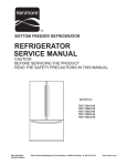
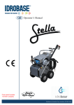
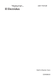
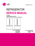
REFRIGERATOR
SERVICE MANUAL
CAUTION
BEFORE SERVICING THE UNIT,
READ THE SAFETY PRECAUTIONS IN THIS MANUAL.
MODELS:
LFC23760ST / 04
LFC23760SW / 04
LFC23760SB / 04
ECN (Engineering Change Number)
Rev.01
Change Cover Lower (improve structure)
SVC Improvement opening door freezer (Change connector rail in order to reduce claims for bad sealing and
door misaligned. New connector rail has 1º degree of inclination)
Rev.02
Valve inclined in order to improve house connection
Rev.03
Change model to Barrierless type & Twisting Ice Maker
Rev.04
Compressor change from MQ53LAUM (PTC) to MQ53LAUM (e-PTC)
CONTENTS
SAFETY PRECAUTIONS ........................................................................................................ 3
1. SPECIFICATIONS ............................................................................................................... 4
2. PARTS IDENTIFICATION .................................................................................................... 5
3. DISASSEMBLY ................................................................................................................... 6
3-1 Fan and Fan Motor.......................................................................................................... 6
3-2 Defrost Control Assembly................................................................................................. 6
3-3 Lamp................................................................................................................................ 6
3-4 Control Box Refrigerator.................................................................................................. 7
3-5 Multiduct.......................................................................................................................... 7
3-6 Cover Valve...................................................................................................................... 9
3-7 Door Disassembly............................................................................................................ 10
3-8 How to remove the Door Handle..................................................................................... 12
3-9 How to remove Pull out drawer........................................................................................ 14
3-10 Closing and aligning the doors...................................................................................... 16
4. ADJUSTMENT .................................................................................................................... 17
4-1 Compressor ................................................................................................................... 17
4-2 PTC-Starter .................................................................................................................... 17
4-3 OLP (overload protector) ............................................................................................... 18
5. CIRCUIT DIAGRAM ............................................................................................................ 19
6. TROUBLESHOOTING ........................................................................................................ 20
6-1 Compressor and electric components ........................................................................... 20
6-2 PTC and OLP ................................................................................................................. 21
6-3 Other electrical components .......................................................................................... 22
6-4 Service diagnosis chart .................................................................................................. 23
6-5 Refrigeration cycle ......................................................................................................... 24
7. OPERATION PRINCIPLE AND REPAIR METHOD OF ICEMAKER .................................. 26
7.1 Operation principle ......................................................................................................... 26
7.2 Ice maker functions ........................................................................................................ 27
8. CIRCUIT OF MICOM............................................................................................................ 30
8.1 Function ......................................................................................................................... 30
8.2 PCB function .................................................................................................................. 34
8.3 Resistance specification of sensor ................................................................................. 38
9. EXPLODED VIEW ............................................................................................................... 39
-2-
SAFETY PRECAUTIONS
Please read the following instructions before
servicing your refrigerator.
1.Check the refrigerator for current leakage.
2.To prevent electric shock,unplug before
servicing.
3.Always check line voltage and amperage.
4.Use standard electrical components.
5.Don't touch metal products in the freezer
with wet hands.This may cause frost bite.
7.Before tilting the refrigerator, remove all
materials from on or in the refrigerator.
8.When servicing the evaporator, wear gloves
to prevent injuries from the sharp evaporator
fins.
9.Service on the refrigerator should be
performed by a qualified technician.Sealed
system repair must be performed by a CFC
certified technician.
6.Prevent water from spiling on to electric
elements or the machine parts.
-3-
SPECIFICATIONS
Color
MODELS
1. SPECIFICATIONS
LFC23760SW /04
LFC23760ST /04
LFC23760SB /04
Super White
Stainless
Black
892 (W) x 925 (D) x 1860 (H) mm
Dimensions
Net Weight
123 Kg
Capacity
23 cuft
Refrigerant
R134a
Climate class
Temperate (T)
Rated Rating
115V~ / 60Hz
GENERAL FEATURES
Cooling System
Fan Cooling
Temperature Control
MICOM control
Full Automatic
Defrosting System
Heater Defrost
Insulation
Cyclo, Pentane
Compressor
MQ53LAUM PTC Starting Type
Evaporator
Fin Tube Type
Condenser
Wire Condenser
Lubricanting Oil
Polyol Ester (POE) RL-7H/7 cst 220 ± 10cc
Drier
MOLECULAR SIEVE XH-7
Capillary Tube
ID Ø0.75
First Defrost
4 Hours
Defrost Cycle
7 - 40 Hours
Desfrosting Device
Heater, Sheath
Anti-freezing Heater
Water Tank Heater
Case Material
FREEZER
REFRIGERATOR
Door Material
Embo (normal)
PCM
Stainless
Handle Type
Vista
Display Graphic
ICE PLUS
Basket, Quantity
3 left + 3 right
Ice Tray & Bank
1B/(1EA)
Lamp
Yes (2) 40W/Blue
Shelf
1Fix(S/Proof)+1Fold+2S/Out(S/Proof)
Tray meat
No
Egg Bank
Yes (Cover + Egg tray)
Basket, Quantity
No
Lamp
Yes (1) 40W/Blue
Shelf
No
-4-
VCM
DIMENSIONS
Description
LFC23760**
Depth w/ Handles
A
34 5 8
Depth w/o Handles
B
32 1 8
Depth w/o Door
C
28 ¼
Depth (Total with Door Open)
D
45 ½
Height to Top of Case
E
67
11
Height to Top of Door Hinge
F
69
1
Width
G
32 ¾
Width (door open 90 deg. w/o handle)
H
36 ¼
Width (door open 90 deg. w/ handle)
I
41 ¼
16
16
2. PARTS IDENTIFICATION
A
L
B
C
M
D
E
N
F
G
H
O
I
P
J
K
Read this section to familiarize yourself with the parts and features of your new refrigerator.
NOTE: This guid ecovers different models. Your refrigerator could have some or all of the features and parts listed
below. The location of some of the parts may not correspond to that of your model.
A Digital Sensor Control *
I Ice Bin
B Refrigerator Light
J Durabase
C Shelves
K Durabase Divider
D Temperature Control *
L Dairy Compartment
E Chef Fresh / Snack Pan
M Egg Compartment *
F Can Dispenser *
N Refrigerator Door Rack
G Optibin Crisper
Keeps fruits and vegetable fresh and crisp
O Freezer Light
P Pull out Drawer
H Icemaker
* On some models
-5-
A
K
B
C
L
D
M
E
F
G
N
H
O
I
J
Read this section to familiarize yourself with the parts and features of your new refrigerator.
NOTE: This guid ecovers different models. Your refrigerator could have some or all of the features and parts listed
below. The location of some of the parts may not correspond to that of your model.
A Digital Sensor Control *
I Durabase
B Refrigerator Light
J Durabase Divider
C Shelves
K Dairy Compartment
D Chef Fresh / Snack Pan
L Egg Compartment *
E Can Dispenser *
M Refrigerator Door Rack
F Optibin Crisper
Keeps fruits and vegetable fresh and crisper
N Freezer Light
O Pull out Drawer
G Icemaker
H Ice Bin
* On some models
-6-
3. DISASSEMBLY
3-1 FAN AND FAN MOTOR
3-3 LAMP
1. Remove the freezer shelf. (If your refrigerator has an
icemaker, remove the icemaker first).
2. Remove the plastic guide for slides on left side by
unscrewing phillips head screws.
3. Remove the grille by removing one screw and pulling the
grille forward.
4. Remove the Fan Motor assembly by loosening 2 screw and
disassemble the shroud.
5. Pull out the fan and separate the Fan Motor and Bracket.
3-3-1 REFRIGERATOR COMPARTMENT LAMP
1. Unplug your refrigerator.
2. Pull out all of the shelves.
3. Slide a flat screwdriver (1) into the opening of the
light bulb, and pull it downwards (2).
1
2
FAN MOTOR
4. Turn the bulb counter clockwise and remove it.
5. Install the new light bulb.
6. Take the cover (1), lock the hooks (2) from the rear part
of the light bulb and push it upwards (3).
BRACKET
MOTOR
FAN
2
GRILLE
1
3-2 DEFROST CONTROL ASSEMBLY
3
Defrost Control assembly consist of Drefrost Sensor and
FUSE-M.
The Defrost Sensor works to defrost automatically. It is
attached to the metal side of the Evaporator and senses its
temperature.
Fuse-M is safety device for preventing over-heating of the
Heater when defrosting.
At 72°C, it turns the Defrost Heater off.
1. Pull out the grille assembly. (Fig. 1)
2. Separate the connector with the Defrost Control assembly
and replace the Defrost Control assembly after cutting the Tie
Wrap. (Fig. 2)
GRILLE ASSEMBLY
3-3-2 FREEZER COMPARTMENT LAMP
1. Unplug refrigerator.
2. Unlock the cover of the light bulb using your thumbs (2).
1
2
3. Remove the light bulb and replace it with a new one.
4. Take the cover (3), lock the hooks of it (4) and push it
upwards (5).
5. Plug the refrigerator back in.
DEFROST-CONTROL
ASSEMBLY
4
Fig. 1
Fig. 2
3
-7-
5
3-4 CONTROL BOX-REFRIGERATOR
1. First, remove all shelves in the refrigerator, than remove the Refrigerator control Box by loosening 2 screws.
CONTROL BOX
COVER LAMP
2. Remove the Refrigerator Control Box by pulling it downward.
3. Disconnect the lead wire on the right position and separate the lamp sockets.
3-5 MULTI DUCT
1. Remove an upper and lower Cap by using a flat screwdriver, and loosen 2 screws.
2. Disconnect the lead wire on the botton position.
-8-
3-6 VALVE COVER (in some models)
3-6-1 DISASSEMBLE
3-6-2 ASSEMBLE
1. Unscrew the back cover.
1. Insert the ribs to the right side of the back cover hole.
2. Unscrew the valve cover from the back side.
2. Screw the valve cover from the back side.
3. Push to the left and release.
3. Screw the back cover.
-9-
3-7 DOOR DISASSEMBLY
1. To remove Refrigerator door
IMPORTANT: Before you begin, turn the refrigerator OFF and
Unplug it. Remove all food and the shelves from the doors.
Right Door
Left Door
5
NOTE: The appearance of the handle might be different.
With the Philips screw driver, loose the two screws from
the upper lid (1) remove it after that.
1
Unplug the switches cable (6) it’s optional, it’s no
neccesary do it for removing the door.
Unplug the switches cable (2) it’s optional, it’s no neccesary
do it for removing the door.
6
Unplug the cable harness pulling up the hook located in
the upper part of it (7) and separate both parts of the
harness (8).
2
With the 10mm socket wrench, loose the two pins from the
hinge (3) and remove it (4).
Upper view of
the harness
3
4
Place the door with the inner face over the surface so it
won't scratch.
- 10 -
3
Front view of
the harness
Right Door
7
2
8
Loose the grounding screw (9) and the pins (10) located
over the hinge, after, lift the hinge and remove it (11).
Place the hinge in its original position (4) assembly the
two pins (5) and the ground screws (6).
10
5
11
4
9
6
Remove the door and place it over its inner face to avoid
scratching.
Plug the cable harness (7) and the switch (8) (just in case
if you unplugged the switch).
2. To install Refrigerator door
Right Door
7
Take the door and place it gently over the pin of the
hinge (1).
8
1
Pin
Place the hinge lid (9) and install both screws (10). Be
sure the door is correctly assembled.
10
9
Be sure the hook (2) (located in the upper part of the door)
matches with the divisor of the refrigerator's door (3).
Check that the sealing patch of the door is leveled to the
refrigerator and that it isn´t bended.
- 11 -
Plug the cable to the switch (16) (just in case if you
unplugged the switch).
Left Door
Take the left door and place it over the hinge (11).
11
16
Place the hinge's lid (17) and screw the two screw (18).
Check that the door is well installed.
18
17
Be sure that the hook (12) located in the upper part of the
door) matches with the splitter of the refrigerator (13).
Check that the sealing patch of the door ends leveled with
the refrigerator and that it isn't bended.
13
Left Door
3-8 HOW TO REMOVE DOOR HANDLE
Loose the screws (1) with the Allen tool 3/32” and remove
the handle (2).
Remove the mounting screws with the ¼” Allen tool (3).
12
Mounting
Screws
3
Screws
Place the hinge in its original position (14) and place the
two screws (15).
1
2
15
14
Allen Wrench
- 12 -
1. To install the handle of the refrigerator
3. To install the freezer's handle
Install the mounting screws over the door (1) place the
handle over them (2) and tight the screws up (3).
Install the mounting screws over the door (1) place the
handle over them (2) and tight the screws up (3).
Mounting
Screws
1
1
Screws
1
2
3
2
3
Allen
Wrench
2. To remove the freezer's handle
With an 3/32” Allen tool, loose the screws (1) located on
the bottom of the handle, remove it (2) remove the screws
from the door (3) with an ¼” Allen tool.
3
3
2
1
- 13 -
3-9 HOW TO REMOVE PULL OUT DRAWER
IMPORTANT: To avoid possible injury or damage to the
product or your property, please use two people to perform
• With both hands, hold both sides of the door and pull up
to separate it.
the following instructions:
1. Removing the Pull Out Drawer
• Pull the drawer out to maximum extension. Remove the
bottom rack (1) by tilting it back a little and then lifting it
off the railing tracks.
1
• With both hands, hold the center of the bar and push it
in so that it is fit to both rails simultaneously.
• Put pressure on the two hangers (2) with your thumbs in
order to lift it up.
• Separate the left and right rail cover.
CAUTION: When removing the drawer, do not hold the
handle. If it comes off, it could cause personal injury.
CAUTION: To place the drawer on the floor, take care
not to damage the floor or hurt your feet with the sharp
edges on the side with the hinges.
2
2. Installing the Pull Out Drawer
• Remove the screws (3) from both sides of the rail track.
3
• With both hands, hold the center of the bar and pull it
outward so that the two rails extend out at the same
time.
- 14 -
• Mount door supports (1) into the tabs on the railing
track (2), starting in the back first and then connecting
the part in the front last, as shown in the figure.
• Align the top holes of the rail cover with the top holes of
the door supports to mount the cover.
1
2
Verify the hole’s
alignment
• Push the drawer down into position and tighten the
screws (3).
3
• With the drawer fully extended, insert the lower basket
over the front part of the rail assembly and then the
back part (4).
• Compare the left and right rail covers on each side.
4
Right
Rail
Left
Rail
WARNING: To prevent entrapment risk and accidental
child or animal suffocation, DO NOT permit them to
play inside of the drawer.
WARNING: DO NOT step ot sit on the Freezer Door.
- 15 -
3-10 CLOSING AND ALIGNING THE DOORS
Closing the Doors
Aligning the Doors
Your refrigerator has two front leveling screws, one on the
right and one on the left. If your refrigerator seems
unstable or if you would like the doors to close more easily,
simply adjust the inclination of the refrigerator by following
the instructions below:
If the spacing between the doors is uneven, follow the
instructions below to align them:
1. Plug the refrigerator into a 3 prong grounded outlet.
Move the refrigerator into its final position.
2. Remove the base grille (Refer to the section on
“Installation of Base Grille”).
1. With one hand, lift up the door you want to raise at
middle hinge.
2. With other hand, use pliers to insert snap ring as
shown.
3. Insert additional snap rings until the doors are aligned.
(Three snap rings are provided per unit.)
3. Use a flat head screwdriver to adjust the leveling
screws, turning clockwise to raise the side of the
refrigerator and counter-clockwise to lower it. It may
take several turns to adjust it to the inclination you
would like.
NOTE: Having someone push against the top of the
refrigerator takes some weight off the leveling screws.
This will make it easier to adjust the screws.
4. Open both doors again and check to make sure that
they close easily. If not, slightly tilt the refrigerator
further back by turning both leveling screws clockwise.
It may take several more turns. Make sure that you
turn both leveling screws the same amount.
5. Ensure that the refrigerator is even by using a level.
6. Replace the base grille.
- 16 -
4. ADJUSTMENT
4-1 COMPRESSOR
4-2-3 PTC-Applied Circuit Diagram
Starting Method for the Motor
4-1-1 Role
The compressor intakes low temperature and low pressure
gas from the evaporator of the refrigerator and compresses
this gas to high-temperature and high-pressure gas. It then
delivers the gas to the condenser.
OVERLOAD PROTECTOR
L1
C
4-1-2 Composition
2
The compressor includes overload protection. The PTC
starter and OLP (overload protector) are attached to the
outside of the compressor. Since the compressor is
manufactured to tolerances of 1 micron and is hermetically
sealed in a dust and moisture-free environment, use
extreme caution when repairing it.
PTC
5
S
3
6
N
COMPRESSOR
MOTOR
M
S
M
C
PTC STARTER
SEALED
TERMINAL
Resistance Starter Capacitor Running
4-1-3 Note for Usage
Fig. 1
(1) Be careful not to allow over-voltage and over-current.
(2) If compressor is dropped or handled carelessly, poor
operation and noise may result.
(3) Use proper electric components appropriate to the
Particular Compressor in your product.
(4) Keep Compressor dry.
If the Compressor gets wet (in the rain or a damp
environment) and rust forms in the pin of the Hermetic
Terminal, poor operation and contact may result.
(5) When replacing the Compressor, be careful that dust,
humidity, and soldering flux don’t contaminate the inside
of the compressor. Dust, humidity, and solder flux
contaminate the cylinder and may cause noise,
improper operation or even cause it to lock up.
4-2-4 Motor Restarting and PTC Cooling
(1) It requires approximately 5 minutes for the pressure to
equalize before the compressor can restart.
(2) The PTC device generates heat during operation.
Therefore, it must be allowed to cool before the
compressor can restart.
4-2-5 Relation of PTC-Starter and OLP
(1) If the compressor attempts to restart before the PTC
device is cooled, the PTC device will allow current to
flow only to the main winding.
(2) The OLP will open because of the over current
condition. This same process will continue (3 to 5
times) when the compressor attempts to restart until
the PTC device has cooled. The correct OLP must be
properly attached to prevent damage to the
compressor.
Parts may appear physically identical but could have
different electrical ratings. Replace parts by part
number and model number. Using an incorrect part
could result in damage to the product, fire, injury, or
possibly death.
4-2 PTC-STARTER
4-2-1 Composition of PTC-Starter
(1) PTC (Positive Temperature Coefficient) is a no-contact
semiconductor starting device which uses ceramic
material consisting of BaTiO3.
(2) The higher the temperature is, the higher the resistance
value. These features are used as a starting device for
the Motor.
4-2-6 Note for Using the PTC-Starter
(1) Be careful not to allow over-voltage and over-current.
(2) Do not drop or handle carelessly.
(3) Keep away from any liquid.
If liquid such as oil or water enters the PTC,
PTC materials may fail due to breakdown of their
insulating capabilities.
(4) If the exterior of the PTC is damaged, the resistance
value may be altered. This can cause damage to the
compressor and result in a no-start or hard-to-start
condition.
(5) Always use the PTC designed for the compressor and
make sure it is properly attached to the compressor.
Parts may appear physically identical but could have
different electrical ratings. Replace parts by part
number and model number. Using an incorrect part
could result in damage to the product, fire, injury, or
possibly death.
4-2-2 Role of PTC-Starter
(1) The PTC is attached to the Sealed Compressor and is
used for starting the Motor.
(2) The compressor is a single-phase induction motor.
Durign the starting operation, the PTC allows current
flow to both the start winding and main winding.
- 17 -
4-3 OLP (OVERLOAD PROTECTOR)
4-3-1 Definition of OLP
(OVERLOAD PROTECTOR cross section)
(1) OLP (OVERLOAD PROTECTOR) is attached to the
Compressor and protects the Motor by opening the
circuit to the Motor if the temperature rises and
activating the bimetal spring in the OLP.
12345678
Electrical
characteristics
part number
330 FBYY
-S1 BOX98
Customer part
number
Lot code/
date code
Physical
termination
part number
(2) When high current flows to the Compressor motor, the
Bimetal works by heating the heater inside the OLP,
and the OLP protects the Motor by cutting off the
current flowing to the Compressor Motor.
4-3-2 Role of the OLP
(1) The OLP is attached to the Sealed Compressor used
for the Refrigerator. It prevents the Motor Coil from
being started in the Compressor.
Part
No. Name
Base, phenolic
(UL 94 V-0 rated)
Movable arm support,
plated steel.
Stationary contact support,
plated steel
Heater support, plated steel
Heater, resistance alloy
Disc, thermostatic alloy
(2) For normal operation of the OLP, do not turn the Adjust
Screw of the OLP in any way.
Movable arm, spring temper
copper alloy
Contact, movable, silver on copper
Contact, stationary, silver on copper
Slug, plated steel
Cover, polyester
(UL 94 V-0 rated)
Pin connector, plated copper alloy
(To engage 2.33/2.66 mm dia. pin)
Fig. 2
- 18 -
5. CIRCUIT DIAGRAM
CIRCUIT DIAGRAM
- 19 -
6. TROUBLESHOOTING
6-1. COMPRESSOR AND ELECTRIC COMPONENTS
1
Power Source.
Remove PTC-Starter
from compressor and
measure voltage
between Terminal C of
compressor and
terminal 5 or 6 of PTC.
YES
(Rated voltage
2
YES
No voltage.
5
Reconnect.
NO
Check connection
condition.
Replace OLP.
Applied voltage isn't
in acceptable range.
(115V ±10%)
2
Check
Check resistance
resistance
of
of motor
motor
compressor.
compressor.
.
Advise customer that
power supply needs to
be checked by an
electrician.
5
The range of resistance is between 1~50 ? (ok)
Check the resistance
between M-C, S-C and
Replace
M-S in motor compressor. Open or short compressor
3
Check
resistance of
PTC-Starter.
Check resistance of
two terminals in
PTC-Starter.
At normal temperature
6.8? +20: OK
4
Check OLP.
Check resistance of two
terminals in OLP.
If power conducts: OK
If not: NG
5
Check
starting state.
Check the power supply
under load.
(Compressor attempting
to re-start after being off
for 5 minutes).
Supply
voltage rating
with ±10%.
YES
3
Did
compressor
4
YES
3
5
Compressor
is OK
Replace the
NO compressor
NO
- 20 -
1
6-2. PTC AND OLP
Separate PTC-Starter
from Compressor and
measure resistance
between No. 5 and 6
of PTC-Starter with a
Tester.
(Figure 1)
Observation value is
115V/60Hz : 6.8 ? ±20%
The resistance value
is 0 ? (short) or
(open).
Separate OLP from
compressor and check
resistance value between
two terminals of OLP whit a
tester.
(Figure 2)
Shows continuity
Open
Check another
electric component.
Replace OLP.
5
6
Normal operation of
compressor is impossible
or poor.
?
Figure 1
- 21 -
Figure 2
Replace PTCStarter.
6-3 OTHER ELECTRICAL COMPONENTS
• Not cooling at all
Compressor
doesn't run.
Check for open short or
incorrect resistance readings
in the following components
Cause
a. Starting devices
Short, open, or broken.
b. OLP
Poor contact
or shorted.
c. Compressor coil
Coil open or shorted.
d. Wiring harness
Poor contact
or shorted.
Replace
indicated component.
• Poor cooling performance
Compressor runs
poorly.
Check starting
voltage.
Low voltage.
Advise customer that
the power supply
needs to be checked
by an electrician.
Fan motor
doesn't run.
Check voltage at
starting devices.
Poor or broken or
open contact.
Check current flowing
in sub-coil of
Compressor.
Shorted.
Check rating of OLP.
Lack of capacity.
Check wiring circuit.
Wire is open or
shorted.
Replace
indicated component.
Coil is shorted
or open.
Check Fan Motor.
Heavy frost buildup on
evaporator
Replace
indicated component.
Check current flow in
the following
components:
Sensor
Fuse-M
Check current flow in
the defrost heater.
- 22 -
Open.
Replace
indicated component.
Open.
Replace
defrost heater.
6-4 SERVICE DIAGNOSIS CHART
COMPLAINT
POINTS TO BE CHECKED
REMEDY
No Cooling.
•
• Check if the power switch is set to OFF.
• Check if the fuse of the power switch is shorted.
• Measure the voltage of the power outlet.
• Plug into the outlet.
• Set the switch to ON.
• Replace the fuse.
• If the voltage is low, correct the wiring.
Cools poorly.
• Check if the unit is placed too close to the wall.
• Check if the unit is placed too close to the stove,
gas cooker, or in direct sunlight.
• Is the ambient temperature too high or
• Place the unit about 4 inches (10 cm) from the wall.
• Place the unit away from these heat sources.
• Check if food put in the refrigerator is hot.
• Did you open the door of the unit too often
• Put in foods after they have cooled down.
• Don't open the door too often and close
it firmly.
• Set the control to Recommended position.
• Check if the Control is set to Warm position.
Foods in the
Refrigerator
are frozen.
•
• Check if the control is set to colder position.
• Is the ambient temperature below 41°F(5°
• Lower the ambient temperature.
• Place foods in the high-temperature section.
(front part)
• Set the control to Recommended position.
• Set the control to Warm position.
Condensartion or ice
forms inside
the unit.
•
• Check if food put in the refrigerator is hot.
• Did you open the door of the unit too
• Seal liquid foods with wrap.
• Put in foods after they have cooled down.
• Don't open the door too often and close
it firmly.
Condensartion forms
in the Exterior Case.
• Check if the ambient temperature and humidity
of the surrounding air are high.
•
• Wipe moisture with a dry cloth. It will disappear
in low temperature and humidity.
• Fill up the gap.
There is abnormal
noise.
•
• Adjust the Leveling Screw, and position the
refrigerator in a firm place.
• Remove the objects.
• Are any unnecessary objects placed
Door does not
close well.
• Check if the Tray Drip is not firmly fixed.
• Check if the cover of the compressor enclosure
in the front lower side is taken out.
• Fix the Tray Drip firmly in the original position.
• Place the cover in its original position.
• Check if the door gasket is dirty with
an item like juice.
•
• Clean the door gasket.
• Position in the firm place and level the
Leveling Screw.
• Make sure food stored in shelves does not prevent
the door from closing.
•
Ice and foods
smell unpleasant.
• Check if the inside of the unit is dirty.
•
• The unit smells of plastic.
• Clean the inside of the unit.
• Wrap foods that have a strong odor.
• New products smell of plastic, but this
will go away after 1-2 weeks.
• Other possible problems:
Check if frost forms in
the freezer.
Not
defrosting
Check Components
of the defrosting
circuit.
Check the
refrigeration system.
The system
is faulty.
Perform sealed
system repair.
Check the
Thermistor.
The operation of
the Thermistor is
incorrect.
- 23 -
Replace the
Thermistor.
6-5 REFRIGERATION CYCLE
• Troubleshooting Chart
STATE OF
THE UNIT
STATE OF THE
EVAPORATOR
PARTIAL
LEAKAGE
Freezer
compartment and
refrigerator don’t
cool normally
Low flowing sound of
refrigerant is heard and frost
forms in inlet only.
COMPLETE
LEAKAGE
Freezer
compartment and
refrigerator don’t
cool normally
Flowing sound of refrigerant
is not heard and frost isn’t
formed.
Freezer
Flowing sound of refrigerant
is heard and frost forms in
inlet only.
CAUSE
TEMPERATURE
OF THE
COMPRESSOR
REMARKS
LEAKAGE
RESTRICTION
A little higher than
ambient
temperature.
- Refrigerant level is low due to a
¥
leak.
- Normal cooling is possible by
restoring
the normal amount of
¥
refrigerant
and repairing the leak.
¥
Equal to ambient
temperature.
- No discharging of refrigerant.
- Normal cooling is possible by
restoring
the normal amount of
¥
refrigerant
and repairing the leak.
¥
A little higher than
ambient
temperature.
- Normal discharging of the
refrigerant.
¥
- The capillary tube is faulty.
Flowing sound of refrigerant
is not heard and frost isn’t
formed.
Equal to ambient
temperature.
- Normal discharging of the
refrigerant.
¥
Cooling operation
stops periodically.
Flowing sound of refrigerant
is not heard and frost melts.
Lower than ambient - Cooling operation restarts when
¥
heating
the inlet of the capillary
temperature.
tube.
¥
COMPRESSION
Freezer and
refrigerator don’t
cool.
Low flowing sound of
refrigerant is heard and frost
forms in inlet only.
A little higher than
ambient
temperature.
- Low pressure at high side of
compressor
due to low
¥
refrigerant
level.
¥
NO
COMPRESSION
No compressing
operation.
Flowing sound of refrigerant
is not heard and there is no
frost.
Equal to ambient
temperature
- No pressure in the high
pressure
part of the compressor.
¥
¥
PARTIAL
compartment and
RESTRICTION refrigerator don’t
cool normally
Freezer
COMPLETE
compartment and
RESTRICTION refrigerator don’t
cool.
MOISTURE
RESTRICTION
DEFECTIVE
COMPRESSION
- 24 -
6-5-1 SEALED SYSTEM DIAGNOSIS
Not Cooling Complaint
All components operating, No airflow problems, Not frosted up as a defrost problem
problem has been isolated to sealed system area
Frost
Pattern?
Partial
None
Equalization
Test
Equalization
Test
Very Fast
Very Slow
Very Slow
Very Fast
Fast
Inefficient
Compressor
Partial
Restriction
Complete
Restriction
Condenser
Temperature
Cap Tube
Sound
Hotter than Normal
Faint
Room Temperature
None to Weak
Air/Low Side
Leak
Loss of Change
Compressor Not
Pumping
Trace of Oil
Yes
No
Leak
Undercharge
(The equalization test is trying to restart a compressor after it has been operating.)
- 25 -
7. OPERATION PRINCIPLE AND REPAIR METHOD OF ICEMAKER
7-1 OPERATION PRINCIPLE
7-1-1 Operation Principle of Icemaker
Power Input
Initial Control
• Adjusts Ejector to Start Position with power on.
Icemaking
Control
• Waits until water in the TRAY is frozen after Icemaker
Starts operation.
Ice Ejection
Control
• Runs MOTOR to drop ice from the tray into the ICE BIN.
Water supply control
TEST Control
• Performs Icemaking Mode after supplying water by operating
the SOLENOID in ICE VALVE.
• To operate LINE and SERVICE, press and hold the Fill Key
for 3 seconds. The icemaking will run through 3 stages:
Harvest
Fill
Icemaking.
1. Turning the Icemaker stop switch off (O) stops the icemaking function.
2. Setting the Icemaker switch to OFF and then turning it back on will reset the icemaker control.
Power Switch
Icemaker
Feeler Arm
- 26 -
7-2 ICEMAKER FUNCTIONS
7-2-1 Start Position
1) When power is initially applied or reapplied after power is cut, it detects level of the TRAY after completion of MICOM
initialization. The detecting lever moves up and down.
2) The level of icemaker tray is judged by output signal, high and low signal, of HALL SENSOR. Make the tray to horizontal by
rotating ice ejection motor in normal or reverse direction so that High/Low signal can be applied to MICOM Pin (P22).
3) If there is no change in signals one minute after the geared motor starts to operate, it stops icemaker operation and check
the signal every hour. It resets initialization of icemaker when it becomes normal. Ice ejection conducts for 1 cycle.
7-2-2 Icemaking Mode
a) Ice making control is carried out from the completion of water supply to the completion of ice making in the TRAY. Ice
making sensor detects the temperature of TRAY and completes ice making.(Ice making sensor is fixed below the TRAY.)
b) Ice making control starts after completion of water supply control or initial control.
Under the ice making control, the F room temperature should be operated with the NOTCH of “Normal/Strong”.
c) It is judged that ice making is completed when ice making sensor temperature reaches at -8℃ after 70 minutes + 10
minutes when water is supplied to the TRAY.
7-2-3 Ice Ejection Mode
a) This is to eject ice from the TRAY after ice making is completed.
b) If Hall IC signal is on within 3.6 seconds after ice ejection motor rotates in normal direction, it does not proceed ice ejection
but waits. If the ice bank is full, ice ejection motor rotates in normal direction in every hour to check the condition of ice bank.
If the ice bank is not full, the water supply control starts after completion of ice ejection control. If the ice bank is full, ice
ejection motor rotates in reverse direction and stops under ice making or waiting conditions.
c) If ice bank is not full, ice ejection starts. The TRAY tilts to the maximum and ice is separated from the TRAY and ice
checking lever raises.
d) Ice ejection motor stops for 1 second if Hall IC signal changes from OFF (low) to ON (high) after 3.6 seconds when ice
ejection motor rotates in normal direction. If there is no change in Hall IC signals within 1 minute after ice ejection motor
operates, ice ejection motor stops as ice ejection motor or hall IC is out of order.
e) If ice ejection motor or Hall IC is abnormal, ice ejection motor rotates in normal direction to exercise initial operation in
every hour. It resets the ice maker if ice ejection motor or Hall IC is normal.
f) The TRAY stops for 1 second at maximum tilted conditions.
g) The TRAY returns to horizontal conditions as ice ejection motor rotates in reverse direction.
h) When the TRAY becomes horizontal , the cycle starts to repeat.
Water Supply – Ice making – Ice ejection – TRAY returns to Horizontal.
- 27 -
MAXIMUM TILTING POINT
Bank is
not full
ON
HALL Sensor
Output Signals OFF
Bank is
full
ON
HALL Sensor
Output Signals OFF
Ice checking AXIS LEVEL 30°
Ice checking
AXIS
-8°-0° -10°
Lock
Icemaking
original point
-32° -41°
A
B
-53° -58°
-160° -170°
Lock
Ice ejection
-80°
C
2±1 sec
Horizontal
Conditions
9±3 sec
8±3 sec
- 28 -
Level Return
Conditions
7-2-4 Test Icemaker Mode
Test function starts when test switch is pressed for more than 3 seconds. User shouldn’t force operation while doing test
mode, service or cleaning.
Test switch will work only when ice tray its in horizontal position, not during ice ejection or water supplying.
When pressing the Test Switch, feeler arm will sense and then ice tray will start ice ejection, after twisting, ice tray
returns to initial position. When returning to horizontal position, water supply will start filling the ice tray. After this, test mode
its done.
Test mode cycle elapsed time of 30 seconds its shown as the next sequence:
Feeler arm sensing – Ice ejecting – Ice tray returns to horizontal position – Water supply.
POWER
SWITCH
TEST
SWITCH
7-2-5 Water Supply Function
This function is for supply water to tray,by the mechanic water valve,when ice ejecting finish and tray return to initial position.
Water supply quantity depend of DIP S/
W.
Water Supply Time Table
No
DISP S/W
S1
S2
Water Supply Time
1
OFF
OFF
9.0
2
ON
OFF
8.0
3
OFF
ON
10.0
4
ON
ON
11.0
Note
DIP S/W Setting will be depend of
water pressure
If water supply setting is changed while system is energized, change will be made immediately. But if change occurs when
water supply function is working, change will be executed next cycle of icemaker
7-2-6 Ice maker stop switch
• Ice Maker Stop S/W ON state, Ice Maker normal operation
• Ice Maker Stop S/W OFF state: Ice Maker do not operate
- 29 -
8. CIRCUIT OF MICOM
8-1 FUNCTION
8-1-1 Function
1. When the appliance is plugged in, it is set to "4" for Refrigerator and "4" for freezer.
You can adjust the Refrigerator and the Freezer control temperature by pressing the ADJUST button.
2. When the power is restored after a power failure, it is automatically set to last setting selected.
*Note: To ERROR CODE on display panel refer to page 32.
REFRIGERATOR TEMP
ADJUST
WARMER
4 IS RECOMMENDED
FREEZER TEMP
COLDER
WARMER
4 IS RECOMMENDED
COLDER
ADJUST
8-1-2 Control of freezer fan motor
1. Freezer fan motor has high and standard RPMs.
2. High RPM is used when electricity is first on, for ICE PLUS , and when refrigerator is overloaded.
But standard RPM is used for general purposes.
3. To improve cooling speed and load corresponding speed, the RPM of freezer fan motor shall change from normal speed
to high speed.
4. High speed (2500RPM) : Initial power on or load corresponding operation, ICE PLUS.
Normal speed ( 2200 RPM): general working conditions.
5. Fan motor stops when refrigerator of freezer door opens.
8-1-3 ICE PLUS
1. The purpose of this function is to intensify the cooling speed of freezer and to increase the amount of ice.
2. Whenever selection switch is pressed, selection/release, the LED will turn ON or OFF.
3. If there is a power cut and the refrigerator is power on again, ICE PLUS function will be canceled.
4.To activate these function you need to press the ICE PLUS key and the LED will turn ON. This function will remain
activated for 24 hrs. The first three hours the compressor and ICE PLUS will be ON. The next 21hours the freezer will
be controlled at the lowest temperature. After 24 hours or if the ICE PLUS key is pressed again, the freezer will
return to its previous temperature.
5. For the first three hours notice the following cases:
(1) Compressor and freezer fan(HIGH RPM) continuously operate for three hours.
(2) If defrost starts during ICE PLUS, ICE PLUS operates for the rest of time after defrost is
completed, when ICE PLUS operation time is less than 90 minutes.
If ICE PLUS operates for more than 90minutes, the ICE PLUS will operate for two hours after
defrost is completed.
(3) If ICE PLUS is pressed during defrost, ICE PLUS LED is on but this function will start seven
minutes after defrost is completed and it shall operate for three hours.
(4) If ICE PLUS is selected within seven minutes after compressor has stopped, the compressor (compressor
delays seven minutes) shall start after the balance of the delay time.
(5) The fan motor in the freezer compartment rotates at high speed during ICE PLUS.
6. For the rest of 21 hours, the freezer will be controlled at the lowest temperature.
8-1-4 Refrigerator Lamp Auto Off
1. To protect the risk of lamp heat, when Refrigerator door opens for 7 min, refrigerator lamp is auto off.
- 30 -
8-1-5 Alarm for Open Door
1. This feature sounds a buzzer when the freezer or refrigerator door is not closed within 1 minute after it is opened.
2. One minute after the door is opened, the buzzer sounds three times each for 1/2 seconds. These tones repeat every 30
seconds.
3. The alarm is cancelled when the freezer or the refrigerator is closed while the buzzer sounds.
Freezer Door Closed
or Refrigerator
Door
Open
Closed
Closed
Open
3 Times
3 Times
3 Times
3 Times
Buzzer
Within 1 min.
1 min.
30 sec
30 sec
30 sec
8-1-6 Buzzer Sound
When the button on the front Display is pushed, a Ding~ Dong~ sound is produced.
8-1-7 Defrosting (removing frost)
1. Defrosting starts each time the COMPRESSOR running time reaches 7 hours.
2. For initial power on or for restoring power, defrosting starts when the compressor running time reaches 4 hours.
3. Defrosting stops if the sensor temperature reaches 46.4°F(8°C) or more. If the sensor doesn’t reach 46.4°F(8°C) in
2 hours, the defrost mode is malfunctioning. (Refer to the defect diagnosis function, 8-1-9.)
4. Defrosting won’t function if its sensor is defective (wires are cut or short circuited)
8-1-8 Electrical Parts Are Turned On Sequentially
Electrical parts such as COMP, defrosting heater, freezer FAN, etc. are turned on in the following order to prevent noise and
parts damage. Several parts are started at the same time at initial power on and are turned off together when TEST is
completed.
OPERATING
Initial power on
Temperature of Defrosting
Sensor is 45°C or more
(when unit is newly
purchased or when moved)
Temperature of defrosting
sensor is lower than 45°C
(when power cuts, SERVICE)
ORDERS
POWER in 1/2 second COMP
ON
ON
POWER
ON
in 1/2 second
Reset to normal operation
from TEST MODE
Total load
OFF
in 1/2 second
COMP
ON
in 7 minute
- 31 -
in 1/2 second
Freezer FAN
ON
Defrosting
heater ON
in 10 second
in 1/2 second
Freezer FAN
ON
COMP
ON
in 1/2 second
Defrosting
heater OFF
Freezer FAN
ON
8-1-9 Defect Diagnosis Function
1. Automatic diagnosis makes servicing the refrigerator easy.
2. When a defect occurs, the buttons will not operate; but the tones. such as ding. will sound.
3. When the defect CODE removes the sign, it returns to normal operation (RESET).
4. The defect CODE shows on the Refrigerator and Freezer Display.
REFRIGERATOR TEMP
ADJUST
WARMER
4 IS RECOMMENDED
ERROR CODE on display panel
No.
FREEZER TEMP
COLDER
WARMER
COLDER
ADJUST
LED OFF LED ON
ERROR INDICATION
ITEM
4 IS RECOMMENDED
CONTENTS
1
Failure of Freezer
Sensor
All Off
Cut or short circuite wire
2
Failure of Refrigerator
Sensor
All Off
Cut or short circuite wire
3
Failure of Defrost
Sensor
All Off
Cut or short circuite wire
4
RT- sensor error
All Off
Cut or short circuite wire
REMARKS
Inspect Connecting
Wires on each sensor
Snapping of defrost
heater or temperature
fuse, pullout of
connector (indicated
minimum 2h after
failure occurs)
All Off
When defrost sensor does
not reach 8°C within 1 hour
after starting defrost
6
Failure of BLDC fan
motor at freezing
compartment
All Off
Poor motor, hooking to
If there is no fan motor
wires of fan, contact of
signal for more than 115s in structures to fan,
operation fan motor
snapping or short
circuit of Lead wires.
7
Failure of Icemaker
Sensor
All Off
Snapping or short circuit of
ice making sensor.
Connecting Wire Test
On Sensor
8
Failure of Icemaker Kit
All Off
Failure of wires such as
motor in I/M KIT, GEAR,
HALL IC.
When the ice ejecting
does not operated on
pressing the I/M TEST
S/W
5
Failure of Defrost
Mode
Primary Error: F sensor, R1 sensor, D sensor, Defrost errors, F-FAN errors.
Secondary Error: I / M sensors, I / M Kit, RT sensor.
When an error occur the first 3 hours the Primary Error and Secondary Error is indicated in the display check mode (Pressing
refrigerator and freezer temperature control button at the same time more than one second). After the 3 hours and if the error
is still present the Primary Error will show in the display automatically (See Note 1) and the Secondary Error is indicated in the
display check mode.
Note1: In the Primary Error after 3 hours of the error occurs all display lights turn OFF except the Freezer Temperature
(Trouble Code Index) indicating the failure mode.
*LED check function: When there’s no error, when the refrigerator temperature control and the freezer temperature control
button at the same time are hold for 1 second or longer, every LED on the display turns on at the same time when the button
are released, the previous mode is restored.
- 32 -
8-1-10 TEST Mode
1. The Test mode allows checking the PCB and the function of the product as well as finding out the defective part in case of
an error.
2. The test mode is operated by pressing two buttons at Display panel.
3. While in the test mode, the function control button is not recognized, but the recognition tone (beep~) sounds.
4. After exiting the test mode, be sure to reset by unplugging and then plugging in the appliance.
5. If an error, such as a sensor failure, is detected while in the test mode, the test mode is cleared and the error code is
displayed.
6. While an error code is displayed, the test mode will not be activated.
MODE
TEST1
MANIPULATION
Push ICE PLUS
key and ADJUST key of
Freezer Temperature at the
same time over 3s.
Or Push TEST switch (on
the main Board) once.
CONTENTS
REMARKS
1. Continuous operation of the compressor
and the freezer fan.
2. Stepping Damper OPEN
3. Defrosting Heater OFF
4 .Display LED all ON
Maximum test time:
5 minutes.
<Cooling MODE>
TEST2
Push ICE PLUS
key and ADJUST key of
Freezer Temperature at the
same time over 3 seconds
in TEST MODE 1
Or Push TEST switch once
In TEST MODE 1.
<Forced desfrosting MODE>
Reset to
Normal
Push ICE PLUS
key and ADJUST key of
Freezer Temp. at the same
time over 3 seconds. in
TEST MODE 2
1. Compressor and the freezer fan OFF
2. Stepping Damper CLOSE
3. Defrosting heater ON
4. Display LED 1, 3, 5, 7 ON
Maximum test time:
2 hours
Reset if the temperature
of the defrosting sensor
is 8°C (46°F) or more.
Reset to initial status (COMP 7 min delay)
* Freezer Fan RPM Variable Check:
In case the freezer fan is in operation when the ADJUST key in Refrigerator and Freezer Temp. Control are pressed for
more than one second at the same time freezer fan RPM changes. (for example if high speed, to normal speed or if
normal speed, to high speed for 30 seconds)
After 30 seconds, it turns to its original RPM.
* Demonstration MODE:
1. When the ICE PLUS key and ADJUST key of refrigerator temperature control are pressed for more than 3 seconds at the
same time temperature’s
.
it converts to demostration mode.
2. In this status, each LED is rotated with 1 second interval.
3. In this status, all Loads are off (Compressor / Fan / Damper / Heater)
(Even is Demonstration Mode, the refrigerator Lamp automatic off function works normally and can be demostrated)
4. It reset if you do again as clause.
- 33-
8-2 PCB FUNCTION
CON 7
CON 6
CON 5
CON 4
CON 8
CON 9
CON 10
CON 1
CON 3
- 34 -
CON 2
8-2-1 Power Circuit
Power is supplied to the control board at the pin 11 and 9 of connector #1. (Refer to figure 1)
CON 1
11 10 9 8 7 6
WH
BL
BN
(SB)
CON 2
5 4 3 2 1
BL
CON 3
3 2 1
BN
BL
9 8 7 6 5 4 3 2 1
SB
PR BN RD
SB
BK
FRENCH DOOR HEATER
POWER
SUPPLY
CORD
5
3
6
M
GN
nc
com
nc
DOOR S/W-R1&R2
A B
/YL
BL
A
B
LAMPS-R
Cs
BL
4
S
nc
LAMP-F
2
RD
(GN)
P.T.C
* ALTERNATIVE COMP'
ACCESSORIES
* P.T.C OPTION
COMP' ACCESSORIES
MC,MQ COMP'
EG COMP'
3
2
*PLUG TYPE, CAPACITOR PART, P.T.C START
OPTION, DOOR HEATER, THERMOSTAT, RT-SENSOR
AND COMP' ACCESSORIES ON CIRCUIT DIAGRAM ARE
SUBJECT TO CHANGE IN DIFFERENT LOCALITIES
AND MODEL TYPE.
BK
CR
BL
OLP
GN/YL
(GN)
ICE VALVE
Cr
com
nc
THERMOSTAT
FUSE-M
(72 C)
PK
DEF-HEATER
L
com
OLP
N
CAPACITOR PART
DOOR S/W-F
com
N
4
5
4
6
3
6
2
5
PTC
L
COMBO KIT
(PTC+OLP)
MEZ62439806
BK: BLACK
YL: YELLOW
SB: SKY BLUE
BN: BROWN
Fig. 1
GN: GREEN
PK: PINK
BO: BRIGHT ORANGE
PR: PURPLE
GY: GRAY
WH: WHITE
BL: BLUE
RD: RED
GN/YL: GREEN/YELLOW
BL/WH: BLUE/WHITE
BK/WH: BLACK/WHITE
RD/WH: RED/WHITE
8-2-2 Load and Door Light Circuit (HV)
1. Load Drive Condition Check
To measure outputs of the control board, check voltages between the pins for the following components:
(Refer to Fig. 1).
Circuit
Pin
Number
Pin
Number
Output
Voltage
Compressor
Con 1 Pin 1
Con 1 Pin 3
115 VAC
Defrost
Heater
Con 2 Pin 7
Con 1 Pin 3
115 VAC
F Lamp
Con 2 Pin 5
Con 1 Pin 3
115 VAC
R Lamp
Con 2 Pin 1
and/or 3
Con 1 Pin 3
115 VAC
Ice Maker
Con 2 Pin 9
Con 1 Pin 3
115 VAC
French Door
Heather
Con 3 Pin 1
Con 3 Pin 3
115 VAC
Connector 1
Pin
11
9
3
1
N
L
N
COMP
Connector 2
Pin
9
7
5
Ice
Valve
Def
Heater
F Lamp
NOTE: When the door of the refrigerator is left open for 7 minutes or longer, the lamp of the refrigerator turns off
automatically.
- 35 -
3
1
R Lamp
To measure the outputs of the sensors, check the voltages between the pins as in the table. And refer the values in the
section “RESISTANCE SPECIFICATION OF SENSOR”
Sensor
Pin Number
Pin Number
F- Sensor
Con 7 Pin 10
Con 7 Pin 11
R- Sensor
Con 7 Pin 8
Con 7 Pin 9
D- Sensor
Con 7 Pin 6
Con 7 Pin 7
I/M Sensor
RT- Sensor
Con 7 Pin 1
Con 8 Pin 1
Con 9 Pin 2
Con 8 Pin 2
To measure the outputs of the fans on the control boards check the voltages between the pins for the following components:
FAN
Pin Number
Output Voltage
Motor On
Motor Off
Pin Number
Freezer Fan
Con 4 Pin 5
Con 4 Pin 6
10-14Vdc
2Vdc or less
Cooling Fan
con 4 Pin 2
Con 4 Pin 3
10-14Vdc
2Vdc or less
Connector 4
PIN
12
11
10
9
NC
NC
8
7
6
Stepping Motor
5
4
3
F-Fan
NC
V
2
C-Fan
G
F
V
3
2
1
8-2-4 ICE MAKER
Connector 9
PIN
10
9
I/M Motor
8
7
Hall IC
6
5
4
I/M Test S/W
I/M Stop S/W
Circuit
Pin Number
Pin Number
Output Voltage
I/M Stop S/W
Con 9 Pin 3
Con 9 Pin 4
0~5Vdc
I/M Test S/W
Con 9 Pin 5
Con 9 Pin 6
0~5Vdc
¥
- 37 -
I/M Sensor
1
NC
G
NC
F-DOOR S/W
CON101
D-SENSOR
RD
BO
BL
SB
PR
BK
PK
WH
YL
1 2 3 4 5 6 7 8 9
R-SENSOR
F-SENSOR
PWB(PCB) ASSEMBLY, DISPLAY
F-FAN
STEPPING
MOTOR
1
2
3
4
5
WH 6
BL 7
BK 8
YL 9
RD 10
11
12
B
BL
BL
WH
WH
BO
BO
PK
PK
SB
BN
1413 12 11 10 9 8 7 6 5 4 3 2 1
6 5 4 3 2 1
CON 5
C-FAN
YL
RD
BO
BL
SB
PR
BK
PK
WH
A
CON 6
1110 9 8 7 6 5 4 3 2 1
CON 7
CON 8
CON 4
SB
BN
PR
GY
PIPE HEATER
CON 9
PWB(PCB) ASSEMBLY, MAIN
4 GY
3 GY
2 BN
1 BN
10 RD
9 WH
8 YL
7 BL
6 BK
5 BN
4 BO
3 BO
2 GY
1 GY
C
R-DOOR S/W
D
RT-SENSOR
M
I/M MOTOR
HALL
IC
I/M TEST S/W
ICE MAKER S/W
STOP S/W PART
I/M SENSOR
ICE MAKER UNIT
Fig. 2
2. Door Monitor Circuit (LV)
Refrigerator
Pin Number
Pin Number
Voltage
F Door Close
Con 7 Pin 4
Con 7 Pin 5
5 Volts
F Door Open
Con 7 Pin 4
Con 7 Pin 5
0 Volts
R Door Close
Con 8 Pin 3
Con 8 Pin 4
5 Volts
R Door Open
Con 8 Pin 3
Con 8 Pin 4
0 Volts
Connector 8
Pin
4
2
3
R-Door S/W
1
RT sensor
8-2-3 Temperature Sensor Circuit (Refer to Figure 2)
Voltage supplied to each sensor will range between 0.5 volts -22°F(-30°C) and 4.5 volts 122°F(50°C) depending upon the
temperature in the compartments. A measurement of 0 volts indicates a short in the sensor circuit. A measurement of 5 volts
indicates an open in the sensor circuit.
Connector 7
PIN
11
10
F-Sensor
9
8
R-Sensor
7
6
D-Sensor
- 36 -
5
4
F-Door S/W
3
2
Pipe Heater
1
NC
8-3 RESISTANCE SPECIFICATION OF SENSOR
TEMPERATURE DETECTED
SENSOR
RESISTANCE OF FREEZER
SENSOR
RESISTANCE OF REFRIGERATOR
DEFROST SENSOR & ROOM SENSOR
-20°C
22.3 K?
77 K?
-15°C
16.9 K?
60 K?
-10°C
13.0 K?
47.3 K?
-5°C
10.1 K?
38.4 K?
0°C
7.8 K?
30 K?
+5°C
6.2 K?
24.1 K?
+10°C
4.9 K?
19.5 K?
+15°C
3.9 K?
15.9 K?
+20°C
3.1 K?
13 K?
+25°C
2.5 K?
11 K?
+30°C
2.0 K?
8.9 K?
+40°C
1.4 K?
6.2 K?
+50°c
0.8 K?
4.3 K?
- The resistance of the SENSOR has a ±5% common difference.
- Measure the resistance of the SENSOR after leaving it for over 3 minutes in the measuring temperature.
This delay is necessary due to sensor response speed.
- 38 -
#EV#
9. EXPLODED VIEW
CASE PARTS
CAUTION: Use the part number to order part, not the position number.
103B
281A
402A
103A
410A
282E
409D
271C
503F
503G
402A
271A
501F
903D
503D
610A
282F
503C
503E
501A
409B
120B
411A
125D
145A
304A
158A
282B
145B
S38
S01
301A
903E
262H
105A
128E
S01
317A
610A
128F
327A
310A
401A
B01
406B
410G
106A
308A
409B
319E
309A
404A
323B
106A
328A
307A
405G
405F
418A
405C
412D
329A
158E
312A
329C
405A
420A
305B
405B
319D
305C
332A
S22
405B
315A
103C
305C
305B
105F
135C
#EV#
FREEZER PARTS
CAUTION: Use the part number to order part, not the position number.
136B
131A
145C
248E
248F
145F
136A
#EV#
REFRIGERATOR PARTS
CAUTION: Use the part number to order part, not the position number.
143E
S24
140B
140D
146A
140E
S24
143E
S24
143E
140B
S24
140D
140B
140D
140E
S24
140E
143F
142D
140B
S24
S24
142E
103E
S24
103E
103E
128A
170A
128B
167B
154A
103E
151A
155B
151A
151C
305D
#EV#
DOOR PARTS
CAUTION: Use the part number to order part, not the position number.
230A
230B
241F
104E
231B
233B
233D
233C
231A
233A
212G
241C
233G
233H
241C
233E
233F
241C
244A
244A
212J
212J
241C
241C
286A
286A
241C
243A
243B
243A
243B
S27
249A
S27
262E
262E
249E
250B
249J
250A
621B
200A
621C
203A
250B
201A
212J
249K
249B
249F
212A
#EV#
ICEMAKER PARTS
CAUTION: Use the part number to order part, not the position number.
600A
622B
627A
616E
619C
S31
MFL62526033
February. 2011
ECN04