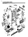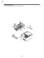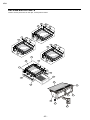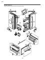
1
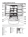
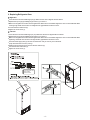
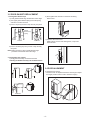
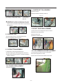
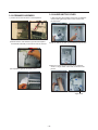
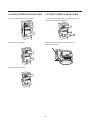
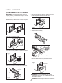
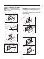
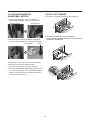
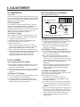
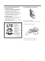
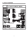
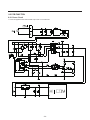
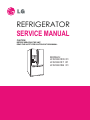
REFRIGERATOR
SERVICE MANUAL
CAUTION
BEFORE SERVICING THE UNIT,
READ THE SAFETY PRECAUTIONS IN THIS MANUAL.
MODELS:
LFX23961SW /01
LFX23961ST /01
LFX23961SB /01
CONTENTS
SAFETY PRECAUTIONS ................................................................................................................................... 2
1. SPECIFICATIONS ........................................................................................................................................... 3
2. PARTS IDENTIFICATION ............................................................................................................................... 4
3. DISASSEMBLY ............................................................................................................................................... 5
4. ADJUSTMENT ................................................................................................................................................ 17
5. CIRCUIT DIAGRAM ........................................................................................................................................ 19
6. TROUBLESHOOTING .................................................................................................................................... 20
7. OPERATION PRINCIPLE AND REPAIR METHOD OF ICEMAKER ............................................................. 25
8. DESCRIPTION OF FUNCTION & CIRCUIT OF MICOM ................................................................................ 28
9. EXPLODED VIEW .......................................................................................................................................... 43
SAFETY PRECAUTIONS
Please read the following instructions before servicing your
refrigerator.
7.Before tilting the refrigerator,remove all materials from
On or in the refrigerator.
1.Check the refrigerator for current leakage.
2.To preven telectric shock,unplug before servicing.
8.When servicing the evaporator,wear gloves to prevent
Injuries from the sharp evaporator fins.
3.Always check line voltage and amperage.
4.Use standard electrical components.
9.Service on the refrigerator should be performed by a
Qualified technician.Sealed system repair must be
Performed by a CFC certified technician.
5.Don't touch metal products in the freezer with wet
Hands.This may cause frost bite.
6.Prevent water from spiling on to electric elements or the
Machine parts.
-2-
SPECIFICATIONS
Color
Dimensions
MODELS
1. SPECIFICATIONS
LFX23961SW LFX23961ST LFX23961SB
Super White
Net Weight
124kg
Capacity
23 cuft
Refrigerant
R134a (120gr)
Climate class
Temperate (N)
Rated Rating
115V~ / 60Hz
GENERAL FEATURES
Cooling System
MICOM control
Full Automatic
Defrosting System
Heater Defrost
Insulation
Cyclo, Pentane
Compressor
LD72LACM PTC Starting Type
Evaporator
Fin Tube Type
Condenser
Wire Condenser
Polyol Ester (POE) 310± 10cc
Drier
MOLECULAR SIEVE XH-7
Capillary Tube
ID Ø0.75
First Defrost
4 Hours
Defrost Cycle
7 - 40 Hours
Desfrosting Device
Heater, Sheath
Anti-freezing Heater
Water Tank Heater
Case Material
REFRIGERATOR
Door Material
Black
Fan Cooling
Temperature Control
Lubricanting Oil
FREEZER
Stainless
892 (W) x 925 (D) x 1860 (H) mm
Embo (normal)
PCM
Handle Type
Stainless
Vista
Display Graphic
ICE PLUS
Basket, Quantity
1 left + 3 right
Ice Tray & Bank
AUTO ICE MAKER
Lamp
Yes (2) 40W/Blue
Shelf
4 Fix
Tray meat
Yes
Egg Bank
No
Basket, Quantity
No
Lamp
Yes (1) 40W/Blue
Tray Drawer F/U
Yes (Full Width)
Tray Drawer F/L
Yes (Plastic)
Shelf
No
-3-
VCM
2. PARTS IDENTIFICATION
I
A
J
B
K
C
E
D
E
F
L
M
G
N
H
O
P
Use this page to become more familiar with the parts and features. Page references are included for your convenience.
NOTE: This guide covers several dierent models. The refrigerator you have purchased may have some or all of the
items listed below. The locations of the features shown below may not match your model.
Ice Bucket
A Refrigerator Light
J Dairy Bin
B Ice Room
K Refrigerator Shelves
C Egg Box
L Freezer Light
D Snack Pan
M Turbo Motor
E Modular Door Bins
N Glide out Drawer
F Water Tank Cover
G Crisper
Ice Room Door
O Durabase
P Divider
*On some models
H Ice Bin
I Filter (Inside)
-4-
3. DISASSEMBLY
3-1 DOORS
1. Removing Refrigerator Door
NOTE: Handle appearance may vary.
IMPORTANT: Before you begin, turn the refrigerator OFF and unplug it. Remove food and any bins from doors.
Left Door
Loosen the screws and remove the cove on back side (see figure A).
Disconnect water supply tube by pushing back on the disconnect ring (3).
Loosen the cover screw (1).
Disconnect door switch wire (2).
Pull out the tube (4).
CAUTION: If a tube end is deformed or worn out, cut the damaged portion away.
Disconnect wire harness (5).
Remove the ground screw (6).
Loosen screws (7) and lift off the top hinge (8).
Place the door on a non-scratching surface with the inside up.
CAUTION: When removing top hinge, be careful that the door does not fall forward.
Right Door
Loosen the cover screw (1).
Disconnect door switch wire (2).
Loosen screws (7) and lift off the top hinge (8).
Place the door on a non-scratching surface with the inside up.
(1)
(1)
(2)
(6)
(4)
(7)
(5)
(7)
(2)
(8)
(8)
Figure A
3
-5-
2. Replacing Refrigerator Door
Right Door
Lower the door onto the middle hinge pin (9). Make sure the door is aligned with the cabinet.
Replace the top hinge (8) installing hinge screws (7) to secure it.
Make sure the gasket on the door is flush against the cabinet and is not folded. Support the door on the handle side while
securing hinge. Make sure the door is straight and the gap between the doors is even.
Connect the door switch wire (2).
Tighten the cover screw (1).
Left Door
Lower the door onto the middle hinge pin (10). Make sure the door is aligned with the cabinet.
Replace the top hinge (8) installing hinge screws (7) to secure it.
Make sure the gasket on the door is flush against the cabinet and is not folded. Support the door on the handle side while
tightening. And make sure the door is straight and the gap between the doors is even.
Insert the water supply tube (4) into the connector tube until you see only one scale mark.
(Fully insert the tube over 5/8” (15 mm)).
Install the ground screw (6) and connect the wire harness (5).
Connect the door switch wire (2).
Tighten the cover screw (1).
Caution
10
Connecting tube color
• Blue to Blue
• White to White
1.
9
-6-
3-2 REMOVING REFRIGERATOR HANDLE
3-4 DOOR GASKET REMOVAL
1.Removing Refrigerator Handle
1. Remove door frame cover
Starting at top of cover and working down, snap cover
out and away from door.
• Loosen the set screws with the 3/32” Allen
wrench and remove the handle.
NOTE: If the handle mounting fasteners
need to be tightened or removed, use a 1/4”
Allen wrench.
Frame Cover
Handle
Mounting
Fasteners
Set Screw
2. Remove gasket bracket clips
There are two clips on each door. Start bracket removal
near one of the middle clips.
1) Pull gasket back to expose gasket bracket clip and
door frame.
2) Insert a flat tip screwdriver into seam between gasket
bracket and door frame and pry back until clips snap
out.
3) Continue prying back along seam until all clips snap
out.
Allen Wrench
Door
Frame
3-3 REMOVING FREEZER HANDLE
2.Removing Freezer Drawer Handle
Gasket
Bracket Clip
Flat Tip
Screwdriver
• Loosen the set screws located on the lower
side of the handle with the 3/32 ” Allen
wrench and remove the handle.
NOTE: If the handle mounting fasteners
need to be tightened or removed, use a 1/4”
Allen wrench.
Gasket
Bracket
3. Remove gasket
Pull gasket free from gasket channel on the three
remaining sides of door.
-7-
3-5 DOOR GASKET REPLACEMENT
1. Insert gasket bracket clips
1) Insert gasket bracket edge beneath door frame edge.
2) Turn upper gasket bracket spring so that the spring
ends are in the door channel.
3) Push in clip until you hear it snap securely into place.
2) Press gasket into channels on the three remaining
sides of door.
Gasket
Bracket Clip
Spring
Door
Frame
Correct
Incorrect
3) Replace door frame cover
Starting at top of cover and working down, snap cover
back into door.
4) Push in remaining clip until you hear it snap securely
into place.
Note: Make sure that no part of gasket bracket edge
protrudes from beneath door frame edge.
2. Insert gasket into channel
1) Snap gasket assembly into the door bracket.
<Inserting the Gasket Assembly into the Bracket Door>
3-6 DOOR ALIGNMENT
If fridge door are uneven,
• Use the wrench to adjust the bolt in the door hinge to adjust
the height.(CCW to raise or CW to lower the height.)
Correct
Incorrect
-8-
3-7 FAN AND FAN MOTOR(EVAPORATOR)
3-8 DEFROST CONTROL ASSEMBLY
1. Remove the freezer shelf. (If your refrigerator has an
icemaker, remove the icemaker first)
2. Remove the plastic guide for slides on left side by
unscrewing phillips head screws.
3. Remove the grille by pulling the grille fan forward.
4. Remove the Fan Motor assembly by loosening 2 screws
and disassembling the shroud.
5. Pull out the fan and separate the Fan Motor and Bracket.
Defrost Control assembly consists of Defrost Sensor and
2 FUSE—M.
The Defrost Sensor works to defrost automatically. It is
attached to the metal side of the Evaporator and senses its
temperature. At 72°C, it turns the Defrost Heater off.
Fuse-M is a safety device for preventing over-heating of
the Heater when defrosting.
1. Pull out the grille assembly.
2. Separate the connector with the Defrost Control
assembly and replace the Defrost Control assembly
FAN MOTOR
GRILLE ASSEMBLY
BRACKET
MOTOR
FAN
GRILLE
* Ice Fan Scroll Assembly Replacement
1) Remove the plastic guide for slides on left side by
unscrewing phillips head screws.
2) Pull the grille forward as shown in the second picture.
3) Disconnect wire harness of the grille
4) Remove the scroll assembly by loosening 3 screws
(1)
(2)
(3)
(4)
-9-
DEFROST-CONTROL
ASSEMBLY
3-9 LAMP
3-10 MULTI DUCT
1. Remove the upper and
lower Caps by using a flat
screwdriver, and remove
2 screws.
2. Disconnect the lead wire
on the bottom position.
3-9-1 Refrigerator Compartment Lamp
1. Unplug Refrigerator, or disconnect power at the circuit
breaker.
2. If necessary, remove top shelf or shelves.
3. Using a flat instrument, gently pry the cover loose in the
front as shown. Rotate downward to remove rear tabs.4.
Make sure the bulbs are cool to the touch.
Turn bulbs counterclockwise to remove.
5. Assemble in reverse order by snapping the Lamp Cover
in, engaging the rear tabs followed by the front tabs.
(Max. 40 W-2EA)
3-11 MAIN PWB
1) Loosen the 3 screws on the PWB cover.
2) Remove the PWB cover
3-9-2 Freezer Compartment Lamp
1. Unplug refrigerator power cord form outlet.
2. Gently pry the lamp cover loose in the back
as shown. Rotate forward to remove the
front tabs.
3. Make sure the bulb is cool to the touch. Turn the
bulb counterclockwise to remove.
4. Replace with a new 40-watt appliance bulb.
5. Insert tabs on front of cover into slots in freezer
ceiling. Push cover up to snap back into place.
3) Disconnect wire harness and replace the main PWB in
1) Pull out the darin 2) Grasp the lower 3) Hold the inner side
part of the dispenser of cover dispenser
firmly ,pull it out.
with both hands at the
handle side to pull it
out forward.
- 10 -
3-15 WATER BUTTON ASSMEBLY
1) Remove screws.
2) Grasp the Button assembly and lift up.
Button Lever
4) If nozzle is interfered with button,
push and pull out the bottom of button
5) Remove the
connected part of
lead wire.
CAUTION: When replacing the dispenser cover in the
reverse order of removal, be careful that the lead wire
does not come out and the water tube is not pinched by
the dispenser.
3-16 DUCT DOOR REPLACEMENT
1) Pull up and out on the dispenser cover to remove.
2) Disconnect the wire harness.
3) Remove the funnel
3-12 DISPLAY PCB
4) Replace in reverse order.
As shown below, remove 1 case PCB fixing screw
Remove the display PCB fixing screw.
Case, PCB
Display PCB
3-13 ICE BUTTON ASSEMBLY
1) Remove the screw fixing the button lever.
2) Push the spring from the hanging hook to remove it.
3) Apply some pressure to the rib in direction and lift the
button in direction.
3-17 ICE CORNER DOOR REPLACEMENT
1) Loosen the front screw as shown in the picture.
2) Lift up the hinge with one hand.
3) Pull out the Ice Corner Door with the other hand.
1
2
Hinge
Button Lever
3-14 FUNNEL REPLACEMENT
Pull down and forward
- 11 -
3-18 ICEMAKER ASSEMBLY
1) Loosen two screws as shown in the first picture.
2) Disconnect the wire harness & ground screw replace
theIcemaker assembly in the reverse order of removal.
3) It separates a ground connection screw.
3-19 AUGER MOTOR COVER
1) After removing the icemaker remove the (5) stainless
screws holding the auger motor cover, shown in the
picutres below.
2) Grip the bottom of motor cover assembly and pull out it.
3) Disconnect wire harness of motor cover assembly.
There is a auger motor on the back, as shown in the
picture.
Auger Motor
- 12 -
3-20 HOW TO REMOVE A DOOR ICE BIN
3-21 HOW TO INSERT A DOOR ICE BIN
1) Grip the handles, as shown in the picture.
1) Insert the Ice Bin, slightly tilting it to avoid touching the
Icemaker. (especially, ice maker lever)
1
2
2) Lift the lower part slightly.
Insert the ice bucket carefully avoid contacing the
automatic shut off arm.
3) Take the Ice Bin out slowly.
- 13 -
3-22 PULL OUT DRAWER
(a) HOW TO INSTALL PULL OUT DRAWER
IMPORTANT: To avoid possible injury, product or
property damage, you will need two people to perform
the following instructions.
• Align the top holes of the rail cover with the top holes of
the door supports to assemble the rail cover.
• With both hands, hold the center of the bar and pull it
out to let both rails out to full extension simultaneously.
Fig. 1
Fig. 5
• Verify the hole’s assembly
• Hook door supports into rail tabs.
Fig. 2
Door Supports
Fig. 6
Rail tabes
• Lower door into final position and tighten the screws.
Fig. 3
Fig. 7
Screws
• With the rails pulled out to full extension, insert the
durabase in the rail assembly.
Fig. 8
Durabase
• Make sure you have a right rail cover for each side.
Right
Rail cover
Left
Rail cover
Fig. 4
W
A
R
N
I
N
G
:
To prevent accidental child and pet
entrapment or suffocation risk. DO NOT allow them to
play inside of drawer.
W
A
R
N
I
N
G
:
DO NOT step or sit down on Freezer Door.
- 14 -
(b) HOW TO REMOVE PULL OUT DRAWER
IMPORTANT: To avoid possible injury, product or
property damage, you will need two people to perform
the following instructions.
• Pull the drawer open to full lower extension. Remove
durabase by lifting it from rail system.
Fig. 9
Durabase
When removing drawer door, do not hold it
C
A
U
T
I
O
N
:
by the handle. Door could fall down and you may be
injured grasp door with both hands as pictured below
When removing.
C
A
U
T
I
O
N
:
When laying down the drawer, be careful
not to damage the floor or hurt your feet with the sharp
edges on hinge side.
• With both hands, hold both sides of the door and pull it
up to separate it from the rails.
Fig. 13
• Press both hangers with yours thumbs to lift it up.
Fig. 10
Fig. 14
Door
supports
Rail tabes
• Separate the left and right rail cover
Fig. 11
• Push rails back into drawe cavity. With both hands,
hold the center of the bar and push it in so that both
rails go back simultaneously.
Fig. 15
• Remove the screws of the rail on both sides.
Fig. 12
Fig. 16
screw
- 15 -
3-24 PULL OUT DRAWER
3-23 FAN AND FAN MOTOR
DISASSEMBLY METHOD
1. To remove, lift basket up and pull out straight out.
1) Using a short screwdriver, loosen one SCREW in
DRAIN PIPE ASSEMBLY and one connected to the
MOTOR COVER.
MOTOR COVER
1
2
R
2) Pull and separate the FAN ASSEMBLY and MOTOR
turning counterclockwise based on the MOTOR SHAFT.
FAN ASSEMBLY
2. To Install, pull both rails out to full extension.
Hook the basket supports into the rail tabs and push to
the back of compartment.
MOTOR
R
The assembly is in the reverse order of the disassembly
and take special care for the following details.
1. Be careful not to bend the tube during assembly.
2. Press the WATER DISPENSER button until water pours
out and check for leakage in the CONNECTOR TUBE (It
differs by the water pressure but usually takes about 2
minutes until water pours out.)
- 16 -
4. ADJUSTMENT
4-1 COMPRESSOR
4-2-3 PTC-Applied Circuit Diagram
4-1-1 Role
Starting Method for the Motor
The compressor intakes low temperature and low pressure
gas from the evaporator of the refrigerator and compresses
this gas to high-temperature and high-pressure gas. It then
delivers the gas to the condenser.
OVERLOAD PROTECTOR
N
4-1-2 Composition
The compressor includes overload protection. The PTC
starter and OLP (overload protector) are attached to the
outside of the compressor. Since the compressor is
manufactured to tolerances of 1 micron and is hermetically
sealed in a dust and moisture-free environment, use
extreme caution when performing repairs.
4-2 PTC-STARTER
4-2-1 Composition of PTC-Starter
(1) PTC (Positive Temperature Coefficient) is a no-contact
semiconductor starting device which uses ceramic
material consisting of BaTiO3.
(2) The higher the temperature is, the higher the resistance
value. These features are used as a starting device for
the Motor.
4-2-2 Role of PTC-Starter
(1) The PTC is attached to the Sealed Compressor and is
used for starting the Compressor Motor.
(2) The compressor is a single-phase induction motor.
The starting operation, the PTC allows current flow to
both the start winding and main winding.
3
2
5
6
LFX25980**
2
3
6
5
C
PTC
2
S
COMPRESSOR
MOTOR
M
M
S
L1
PTC STARTER
4-1-3 Note for Usage
(1) Be careful not to allow over-voltage and over-current.
(2) If compressor is dropped or handled carelessly, poor
operation and noise may result.
(3) Use proper electric components appropriate to the
Particular Compressor in your product.
(4) Keep Compressor dry.
If the Compressor gets wet (in the rain or a damp
environment) and rust forms in the pin of the Hermetic
Terminal, poor operation and contact may result.
(5) When replacing the Compressor, be careful that dust,
humidity, and soldering flux don’t contaminate the inside
of the compressor. Dust, humidity, and solder flux
contaminate the cylinder and may cause noise,
improper operation or even cause it to lock up.
LFX21980**
SEALED
TERMINAL
Resistance Starter Capacitor Running
4-2-4 Motor Restarting and PTC Cooling
(1) It requires approximately 5 minutes for the pressure to
equalize before the compressor can restart.
(2) The PTC device generates heat during operation.
Therefore, it must be allowed to cool before the
compressor can restart.
4-2-5 Relation of PTC-Starter and OLP
(1) If the compressor attempts to restart before the PTC
device is cooled, the PTC device will allow current to
flow only to the main winding.
(2) The OLP will open because of the over current
condition. This same process will continue (3 to 5
times) when the compressor attempts to restart until
the PTC device has cooled. The correct OLP must be
properly attached to prevent damage to the
compressor.
Parts may appear physically identical but could have
different electrical ratings. Replace parts by part
number and model number. Use only approved
substitute parts.
4-2-6 Note for Using the PTC-Starter
(1) Be careful not to allow over-voltage and over-current.
(2) Do not drop or handle carelessly.
(3) Keep away from any liquid.
If liquid such as oil or water enters the PTC,
PTC materials may fail due to breakdown of their
insulating capabilities.
(4) If the exterior of the PTC is damaged, the resistance
value may be altered. This can cause damage to the
compressor and result in a no-start or hard-to-start
condition.
(5) Always use the PTC designed for the compressor and
make sure it is properly attached to the compressor.
Parts may appear physically identical but could have
different electrical ratings. Replace parts by part
number and model number. Use only approved
substitute parts.
- 17 -
4-3 OLP (OVERLOAD PROTECTOR)
4-4 TO REMOVE THE COVER PTC
4-3-1 Definition of OLP
(1) OLP (OVERLOAD PROTECTOR) is attached to the
Compressor and protects the Motor by opening the
circuit to the Motor if the temperature rises and
activating the bimetal spring in the OLP.
(2) When high current flows to the Compressor motor, the
Bimetal works by heating the heater inside the OLP,
and the OLP protects the Motor by cutting off the
current flowing to the Compressor Motor.
4-3-2 Role of the OLP
(1) The OLP is attached to the Sealed Compressor used
for the Refrigerator. It prevents the Motor Coil from
being started in the Compressor.
(2) For normal operation of the OLP, do not turn the Adjust
Screw of the OLP in any way.
(2) Disconnect two housing upper side of comp connected
in.
(OVERLOAD PROTECTOR cross section)
12345678
330 FBYY
Electrical
characteristics
part number
-S1 BOX98
Customer part
number
Lot code/
date code
Physical
termination
part number
(1) Remove the Cover Back M/C.
Part
No.
Name
(3) Loosen two screws on comp base.
Base, phenolic
(UL 94 V-0 rated)
Movable arm support, plated steel
Stationary contact support,
plated steel
Heater support, plated steel
Heater, resistance alloy
Disc, thermostatic alloy
Movable arm, spring temper
copper alloy
Contact, movable, silver on copper
Contact, stationary, silver on copper
Slug, plated steel
Cover, polyester
(UL 94 V -0 rated)
Pin connector, plated copper alloy
(To engage 2.33/2.66 mm dia. pin)
Quick-connect terminal, brass,
conforms to UL 310, MEMA
DC-2, DIN 46344
1
3
2
Figure 19
(4) Use a L-shaped flap tool to pry off the cover.
(5) Assembly in reverse order of disassembly.
- 18 -
5. CIRCUIT DIAGRAM
DUCT - HTR
F - LAMP
6
C
S
M
P.T.C.
COMP’ ACCESSORIES
c
ICE MAKER
POWER S/W
b
N
ICE MAKER KIT
a
YL 1
2
BL 3
4
BO 5
6
7
ICE VALVE
d
d
PILOT VALVE
1
2
3
4
5
6
WH/BK
BO
BN
RD
BL
BL
ICING - SENSOR
BL/WH
CON2
WH/RD 1
BL/WH 2
CON1
PWB ASSEMBLY, LAMP
BK: BLACK
YL: YELLOW
SB: SKY BLUE
BN: BROWN
WH/RD
BL/WH
1
2
3
CON103
CON101
CON2
*P.T.C. OPTION
LD, MQ COMP’
1
2
M
AUGER MOTOR
SOLENOID CUBE
WATER/PILOT VALVE
SOLENOID DISPENSER
*COMP’ ACCESSORIES
3
4
5
4
6
3
6
2
5
CON1
PWB ASSEMBLY, LAMP
GN: GREEN
PK: PINK
BO: BRIGHT ORANGE
PR: PURPLE
GY: GRAY
WH: WHITE
BL: BLUE
RD: RED
- 19 -
CR
BL
f
DISPENSER
LED
e
PWB ASSEMBLY,
S/W
EG COMP’
2
WH/RD
BL/WH
RD
PR
BK
SB
CON102
PWB ASSEMBLY, DISPLAY
CON1
*PLUG TYPE, CAPACITOR PART, P.T.C. AND
COMP’ ACCESSORIES ON CIRCUIT DIAGRAM ARE
SUBJECT TO CHANGE IN DIFFERENT LOCALITIES
AND MODEL TYPE.
1
2
3
e
ICE LEVER S/W
RT - SENSOR
6
5
4
3
2
1
GN/YL
WH/RD
WATER PIPE - HTR
1
2
3
4
5
6
7
8
9
10
11
12
F - SENSOR
WH/BK
BO
BN
RD
BN
BN
CON5
BK 1
WH 2
NEUTRAL
R - SENSOR
f
PLUG TYPE
LIVE
CON4
CON6
CON2
L
D - SENSOR
DOOR DUCT - HTR
5
1
2
3
4
4
3
PWB ASSEMBLY, DISPLAY
F - DOOR S/W
BK
OLP
OLP
CON1
STEPPING
MOTOR
a
1
2
3
4
5
6
7
8
COMP’
2
BL
BK
YL
RD
SB
SB
BO
BO
WH
WH
BL
BL
DISPENSER
LED
1
2
3
4
5
6
7
8
9
10
11
12
b
PK
CON3
CAPACITOR
CR PART
CS
c
RD
BL
YL
BN
FUSE - M
R - DOOR S/W
13 WH/RD
12 BL/WH
11 SB
10 YL
9 WH
8 PK
7 WH/BK
6 GY
5 BL
4 BO
3 RD
2 BN
1 BK
SHEAT - HTR
GY
GY
CON4
WH
BO
RD
BL
YL
BN
SB
PK
d
C - FAN
BL
WH
YL
GY
THERMOSTAT
R - LAMPS
ICING
F - FAN
SB 11
10
WH 9
8
WH/BK 7
GY 6
BL 5
BO 4
RD 3
BN 2
BK 1
GY
SB
BN
PR
PK
BO
BK
FD - HTR
F - FAN
WATER
LEVER S/W
OUT PLATE - HTR
WH
BK
PR
RD
BL
BN
SB
BO
ICE MAKER POWER
S/W DETECTION
BL
BO
BL
d
BARRIER - HTR
1
2
3
4
5
6
7
8
9
10
11
1
2
3
4
5
6
7
8
9
10
11
12
FRONT - HTR
N
PTC
L
COMBO KIT
(PTC + OLP)
GN/YL: GREEN/YELLOW
BL/WH: BLUE/WHITE
BK/WH: BLACK/WHITE
RD/WH: RED/WHITE
6. TROUBLESHOOTING
6-1 COMPRESSOR AND ELECTRIC COMPONENTS
1
Power Source.
YES
Remove PTC-Starter
from Compressor and
measure voltage
between Terminal C of
Compressor and
Terminal 5 or 6 of PTC.
(Rated Voltage
–10%)?
No Voltage.
OLP disconnected?
2
YES
Reconnect.
NO
5
Check connection
condition.
Replace OLP.
Applied voltage isn’t
in acceptable range.
(115V –10%)
Advise customer that
power supply needs to be
checked by an electrician.
The range of resistance is between 1~50½(ok)
Check
resistance of
Motor
Compressor.
Check resistance
between M-C, S-C and
M-S in Motor
Compressor.
3
Check
resistance of
PTC-Starter.
Check resistance of
two terminals in
PTC-Starter.
At normal temperature
6.8? +20: OK
4
Check OLP.
Check resistance of two
terminals in OLP.
If power conducts: OK
If not: NG
5
Check
starting state.
Check the power supply
under load.
(Compressor attempting
to re-start after being off
for 5 minutes).
2
5
Open or short
Replace
Compressor.
Supply
voltage rating
with –10%.
YES
3
Did
compressor
start?
4
YES
NO
NO
- 20 -
3
5
Compressor
is OK
Replace the
compressor
1
6-2 OTHER ELECTRICAL COMPONENTS
• Not cooling at all
Compressor
doesn’t run.
Check for open short or
incorrect resistance readings
in the following components
Cause
a. Starting devices
Short, open, or broken.
b. OLP
Poor contact
or shorted.
c. Compressor coil
Coil open or shorted.
d. Wiring harness
Poor contact
or shorted.
Replace
indicated component.
• Poor cooling performance
Compressor runs
poorly.
Fan motor
doesn’t run.
Check starting
voltage.
Low voltage.
Advise customer that
the Power supply
needs to be checked
by an electrician.
Check voltage at
starting devices.
Poor or broken or
open contact.
Replace
indicated component.
Check current flowing
in sub-coil of
Compressor.
Shorted.
Check rating of OLP.
Lack of capacity.
Check wiring circuit.
Wire is open or
shorted.
Coil is shorted
or open.
Check Fan Motor.
Heavy frost buildup on
EVAPORATOR.
Replace
indicated component.
Check current flow in
the following
components:
Sensor
Fuse-M
Check current flow in
the Defrost Heater.
- 21 -
Open.
Replace
indicated component.
Open.
Replace
Defrost Heater.
6-3 SERVICE DIAGNOSIS CHART
COMPLAINT
POINTS TO BE CHECKED
No Cooling.
•Is the power cord unplugged from the outlet?
• Check if the power switch is set to OFF.
• Check if the fuse of the power switch is shorted.
• Measure the voltage of the power outlet.
• Plug into the outlet.
• Set the switch to ON.
• Replace the fuse.
• If the voltage is low, correct the wiring.
Cools poorly.
• Check if the unit is placed too close to the wall.
• Check if the unit is placed too close to the stove,
gas cooker, or in direct sunlight.
• Is the ambient temperature too high or
the room door closed?
• Check if food put in the refrigerator is hot.
• Did you open the door of the unit too often
or check if the door is sealed properly?
• Check if the Control is set to Warm position.
• Place the unit about 4 inches (10 cm) from the wall.
• Place the unit away from these heat sources.
Food in the
Refrigerator
is frozen.
• Is food placed in the cooling air outlet?
• Check if the control is set to colder position.
• Is the ambient temperature below 41°F(5°C)?
• Place foods in the high-temperature section.
(front part)
• Set the control to Recommended position.
• Set the control to Warm position.
Condensation or ice
forms inside
the unit.
• Is liquid food sealed?
• Check if food put in the refrigerator is hot.
• Did you open the door of the unit too
often or check if the door is sealed properly?
• Seal liquid foods with wrap.
• Put in foods after they have cooled down.
• Don’t open the door too often and close
it firmly.
Condensation forms
in the Exterior Case.
• Check if the ambient temperature and humidity
of the surrounding air are high.
• Is there a gap in the door gasket?
• Wipe moisture with a dry cloth. It will disappear
in low temperature and humidity.
• Fill up the gap.
There is abnormal
noise.
• Is the unit positioned in a firm and even place?
• Adjust the Leveling Screw, and position the
refrigerator in a firm place.
• Remove the objects.
• Are any unnecessary objects placed
in the back side of the unit?
• Check if the Drip Tray is not firmly fixed.
• Check if the cover of the compressor enclosure
in the lower front side is taken out.
Door does not
close well.
• Check if the door gasket is dirty with
an item like juice.
• Is the refrigerator level?
Ice and foods
smell unpleasant.
• Lower the ambient temperature.
• Put in foods after they have cooled down.
• Don’t open the door too often and close
it firmly.
• Set the control to Recommended position.
• Fix the Drip Tray firmly in the original position.
• Place the cover in its original position.
• Clean the door gasket.
• Is there too much food in the refrigerator?
•
REMEDY
• Check if the inside of the unit is dirty.
• Are foods with a strong odor unwrapped?
• The unit smells of plastic.
• Position in a firm place and level the
Leveling Screw.
• Make sure food stored in shelves does not prevent
the door from closing.
• Clean the inside of the unit.
• Wrap foods that have a strong odor.
• New products smell of plastic, but this
will go away after 1-2 weeks.
Other possible problems:
Check if frost forms in
the freezer.
Not
defrosting
Check Components
of the defrosting
circuit.
Check the
refrigeration system.
The system
is faulty.
Perform sealed
system repair.
Check the
Thermistor.
The operation of
the Thermistor is
incorrect.
- 22 -
Replace the
Thermistor.
6-4 REFRIGERATION CYCLE
• Troubleshooting Chart
CAUSE
STATE OF
THE UNIT
STATE OF THE
EVAPORATOR
TEMPERATURE
OF THE
COMPRESSOR
REMARKS
LEAKAGE
CLOGGED BY DUST
PARTIAL
LEAKAGE
Freezer
compartment and
Refrigerator don’t
cool normally.
Low flowing sound of
Refrigerant is heard and
frost forms in inlet only.
A little higher
than ambient
temperature.
• Refrigerant level is low due
¥ to a leak.
• Normal cooling is possible by
¥ restoring the normal amount of
¥refrigerant and repairing the leak.
COMPLETE
LEAKAGE
Freezer
compartment and
Refrigerator don’t
cool normally.
Flowing sound of refrigerant
is not heard and frost isn’t
formed.
Equal to ambient
temperature.
• No discharging of Refrigerant.
• Normal cooling is possible by
¥ restoring the normal amount of
¥ refrigerant and repairing the leak.
PARTIAL
CLOG
Freezer
compartment and
Refrigerator don’t
cool normally.
Flowing sound of refrigerant
is heard and frost forms
in inlet only.
A little higher
than ambient
temperature.
• Normal discharging of the
¥ refrigerant.
• The capillary tube is faulty.
WHOLE
CLOG
Freezer
Flowing sound of refrigerant
compartment and
is not heard and frost isn’t
refrigerator don’t cool. Formed.
Equal to ambient
temperature.
• Normal discharging of the
¥ Refrigerant.
Cooling operation
stops periodically.
Flowing sound of refrigerant
is not heard and frost melts.
Lower than
ambient
temperature.
• Cooling operation restarts
¥ when heating the inlet of the
¥ capillary tube.
COMPRESSION
Freezer and
Refrigerator
don’t cool.
Low flowing sound of
refrigerant is heard and
frost forms in inlet only.
A little higher
than ambient
temperature.
• Low pressure at high side
¥ of compressor due to low
¥ refrigerant level.
NO COMPRESSION
No compressing
operation.
Flowing sound of refrigerant
is not heard and there is
no frost.
Equal to ambient
temperature.
• No pressure in the high
¥ pressure part of the
¥ compressor.
MOISTURE
CLOG
DEFECTIVE
COMPRESSION
- 23 -
6-4-1 SEALED SYSTEM DIAGNOSIS
“Not Cooling” Complaint
All components operating, No airflow problems, Not frosted up as a defrost problem
problem has been isolated to sealed system area
Frost
Pattern?
Partial
None
Equalization
Test
Equalization
Test
Very Fast
Very Slow
Very Slow
Very Fast
Fast
Inefficient
Compressor
Partial
Restriction
Complete
Restriction
Condenser
Temperature
Cap Tube
Sound
Hotter than Normal
Faint
Room Temperature
None to Weak
Air/Low Side
Leak
Loss of Change
Compressor Not
Pumping
Trace of Oil
Yes
No
Leak
Undercharge
(The equalization test is trying to restart a compressor using a start kit after it has been operating.)
- 24 -
7. OPERATION PRINCIPLE AND REPAIR METHOD OF ICEMAKER
7-1 OPERATION PRINCIPLE
7-1-1 Operation Principle of IceMaker
Power On
Start Position
Icemaking
Mode
• Adjusts EJECTOR to Start Position with power on.
• Waits until water becomes ICE after starting the
icemaking operation.
Harvest
Mode
• Runs MOTOR to drop ice from the tray into the ICE BIN.
(During harvest mode, check if the ice bin is full)
Park Position
Fill
• Reaches Start Position
• Performs Ice Making Mode after supplying water by operating
the SOLENOID in ICE VALVE.
• To operate LINE and SERVICE, press and hold the Fill Key
for 3 seconds. The icemaker will run through 3 stages:
Harvest
Fill
Icemaking.
Test Mode
1. Turning the Icemaker stop switch off (O) stops the ice making function.
2. Setting the Icemaker switch to OFF and then turning it back on will reset the icemaker control.
Icemaker
Ejector
Automatic
Shut off Arm
Cube Size
Indicator Light
Power Switch
Cube Size
Select Button
- 25 -
7-2 ICE MAKER FUNCTIONS
7-2-1. Icemaking Mode
1. Icemaking refers to the freezing of supplied water in the ice tray. Complete freezing is assured by measuring the
temperature of the Tray with Icemaking SENSOR.
2. Icemaking starts after completion of the water fill operation.
3. The Ice Making function is completed when the sensor reaches 19°F (-7°C), 55 minutes after starting.
NOTE :After Icemaker Power is ON, the Icemaker heater will be on for test for 6 sec.
7-2-2. Harvest Mode
1. Harvest (Ice removing) refers to the operation of dropping ices into the ice bin from the tray when icemaking has
completed.
2. Harvest mode:
(1) The Heater is ON for 30 seconds, then the motor starts.
(2) The feeler arm senses the quantity of ice in the ice storage bin while rotating with the EJECTOR.
A. Ice storage bin is full : The EJECTOR stops (heater off).
B. Ice storage bin is not full : The EJECTOR rotates twice to open for ice.
If the EJECTOR does not rotate once within 5 minutes in B mode, separate heater control mode starts operating to
prevent the EJECTOR from being constrained. (It is recommended that the user open for ice to return to normal mode.)
7-2-3. Fill/Park Position
1. Once a normal harvest mode has been completed, the water solenoid will be activated.
2. The amount of water is adjusted by pressing the Fill Key repeatedly. This changes the time allowed for fill as illustrated in
the table below.
Water supply amount TABLE
STAGE
TIME TO SUPPLY
1
5 sec.
INDICATIONS
REMARKS
The water amount will vary depending
2
on the water control Switch setting, as
5.5 sec.
well as the water pressure of the
(FIRST STAGE)
connected water line.
3
6 sec.
- 26 -
7-2-4 Function TEST
1. This is a forced operation for TEST, Service, cleaning, etc. It is operated by pressing and holding the Fill Key for 3 seconds.
2. The test works only in the Icemaking Mode. It cannot be entered from the Harvest or Fill mode.
3. Caution!If the test is performed before water in the icemaker is frozen, the ejector will pass through the water. When the
Fill mode begins (Stage 4), unless the water supply has been shut off, added water will overflow into the ice bin. If the
control doesn´t operate normally in the TEST mode, check and repair as needed.
4. After water is supplied, the normal CYCLE is followed: icemaking→ Harvest → Park Position → Fill.
5. Five seconds after Stage 5 is completed, the Ice Maker returns to MICOM control. The time needed to supply water
resets to the pre- test setting.
Diagnosis TABLE
STAGE
ITEMS
INDICATOR
REMARKS
1
HEATER
Five seconds after heater starts, a
heater will go off if the temperature by
sensor is higher than 10°C
2
MOTOR
Five seconds after heater starts, you
can confirm that a motor is moving.
3
HALL IC I
Check if Ice Bin is full or not.
If Ice bin is full, the motor and heater
are off and on stand by until Ice bin is empty.
4
HALL IC II
You can confirm HALL IC detection of start
position.
5
VALVE
6
Reset
Two seconds after detection of start position,
you can confirm that valve is on.
Five seconds after fifth stage is completed,
The icemaker resets to initial status.
Return to Status prior to
TEST MODE
7-3 DEFECT DIAGNOSIS FUNCTION
7-3-1 ERROR CODES shown on Ice Maker water supply control panel
NO
DIVISION
1
Normal
2
Icemaking
Sensor
malfunction
INDICATOR
CONTENTS
Mark time to
supply
REMARKS
None
Display switch
operates properly
Open or short-circuited wire
Make sure that the wire
on each sensor is
connected.
- 27 -
8. DESCRIPTION OF FUNCTION & CIRCUIT OF MICOM
8-1 FUNCTION
8-1-1 Display Function
1) When the appliance is plugged in, it is set to 37°F for refrigerator and 0°F for freezer. You can adjust the Refrigerator and
the Freezer control temperature by pressing the ADJUST button.
2) When the power initially applied or restored after a power failure, it is set to Control temperature previously.
ICE OPTION
ICE OPTION
8-1-2. How to Toggle the Display between °F & °C
The initial setting is °F and the display temperature mode can be changed from °F to °C or °C to °F by pressing and
holding the FREEZER and the REFRIGERATOR keys at the same time for over 5 seconds.
8-1-3 Lock function (dispenser and display button lock)
1) When the refrigerator is first turned on, the buttons are not locked. The display panel shows the padlock unlocked icon.
2) To lock the display, the dispenser, and the control panel, press, and hold the ALARM/LOCK button for 3 seconds. The
locked pad lock icon is displayed.
3) The ALARM/LOCK button is the only control feature that remains active in the locked state. The buzzer sound, other
control buttons, and the dispenser are deactivated.
4) To release from the locked state, press and hold the ALARM/LOCK button again for 3 seconds.
Ex) “LOCK” Ex) “LOCK”
Function ON Function OFF
8-1-4 Filter condition display function
1) There is a replacement indicator for the filter cartridge on the dispenser.
2) Water filter needs replacement once six months.
3) Initial month indication is 6 month.
Water filter icon turn on to tell you need to replace the filter soon.
4) When filter indicator becomes 0 MONTH “HOLD 3SECS” text will be lighting.
5) After 6 MONTH has passed, “ 0 “ month is shown on display to indicate the filter has to be exchanged.
6) When 6 MONTH has passed or when filter month indication wants to be Reset press 3 seconds the filter button and
the graphic light will come off and month display will be 6 (six).
In initial Power On
/ Filter RESET
- 28 -
Replace indicator
light on
8-1-5 Ice Plus selection
Please select this function for quick freezing.
* Function is repeat Ice Plus Icon whenever pressing Ice Plus button.
* Ice Plus function automatically turns off after a fixed time passes.
8-1-6 Dispenser Use Selection
1. Water
1) Water Switch: Hold your cup in the dispenser for a fez seconds with
pressing water switch to allow the last drops of water to fall into the cup.
2) Active water button: Place big bowl on the dispenser bottom with pressing
active water button to allow the last drop of water to fall into the bowl.
3) When after initially establishing the wqter comes out, the water tank inside
fills and until at the time of quiality the hour es caught.
2. Ice
1) You can select cube or crushed ice.
2) Select cube ice or crushed ice by cycling through the selections when
pressing the ICE OPTION button.
3) Hold your cup in the dispenser for a few seconds with pressing ice switch to
allow the last pieces of ice to fall into the cup.
PUSH
ACTIVE WATER BUTTON
WATER SWITCH
ICE SWITCH
8-1-7 Dispenser Light
Please select this function for DISPENSER LIGHT MODE.
1. Normal status (LIGHT icon is OFF): When dispenser is operated, DISPENSER LIGHT is ON.
2. ON status (LIGHT icon is ON): DISPENSER LIGHT is on continuously
8-1-8 Control of Freezer Fan Motor
1. Freezer fan motor has high and standard speeds.
2. High speed is used at power-up, for Ice Plus, and when refrigerator is overloaded.
Standard speeds is used for general purposes.
3. To improve cooling speed, the RPM of the freezer fan motor change from normal speed to high.
4. High speed (2700RPM) : Initial power on or load corresponding operation, Ice Plus
Normal speed (2400RPM) : General working conditions.
5. Fan motor stops when refrigerator open.
8-1-9 Cooling Fan Motor
1. The cooling fan is switched ON and OFF in conjunction with the compressor.
2. The cooling fan runs at a single speed.
3. The Failure sensing mathod is the same as in the fan motor of the freezing fan motor(refer to failure diagnosis function
table for failure display).
8-1-10 Icing Fan
1. The Icing Fan is controlled by the the sensor on the top of the ice room.
2. The Failure sensing method is the same as in the fan motor of the freezer
(refer to failure diagnosis function table for failure display)
- 29 -
8-1-11 Ice Plus
1. The purpose of this function is to intensify the cooling speed of freezer and to increase the amount of ice.
2. Whenever selection switch is pressed, selection/release, the Icon will turn ON or OFF.
3. If there is a power outage and the refrigerator is powered on again, Ice Plus will be canceled.
4. To activate this function, press the Ice Plus key and the Icon will turn ON. This function will remain activated for 24 hrs.
The first three hours the compressor and Freezer Fan will be ON. The next 21 hours the freezer will be controlled at the
lowest temperature. After 24 hours or if the Ice Plus key is pressed again, the freezer will return to its previous
temperature.
5. During the first 3 hours:
(1) Compressor and freezer fan (HIGH RPM) run continuously.
(2) If a defrost cycle begins during the first 90 minutes of Ice Plus, the Ice Plus cycle will complete its cycle after
defrosting has ended.
If the defrost cycle begins when Ice Plus has run for more than 90 minutes, Ice Plus will run for two hours after the
defrost is completed.
(3) If Ice Plus is pressed during defrost, Ice Plus Icon is on but this function will start seven minutes after defrost is
completed and it shall operate for three hours.
(4) If Ice Plus is selected within seven minutes after compressor has stopped, the compressor (compressor delays seven
minutes) shall start after the balance of the delay time.
(5) The fan motor in the freezer compartment runs at high speed during Ice Plus.
6. For the rest of the 21 hours, the freezer will be controlled at the lowest temperature.
8-1-12 Alarm for Open Door
1. This feature sounds a buzzer when the freezer or refrigerator door is not closed within 1 minute after it is opened.
2. One minute after the door is opened, the buzzer sounds three times each for 1/2 seconds. These tones repeat every 30
seconds.
3. The alarm is cancelled when the freezer or the refrigerator is closed while the buzzer sounds.
Freezer Door Closed
or Refrigerator
Door
Open
Closed
Closed
Open
3 Times
3 Times
3 Times
3 Times
Buzzer
Within 1 min.
1 min.
- 30 -
30 sec
30 sec
30 sec
8-1-13 Defrosting (removing frost)
1. Defrosting starts each time theaccumulated COMPRESSOR running time is between 7:30 and 40 hours. This time is
determinated by how often and how long the doors are opened.
2. For initial power on or for restoring power, defrosting starts when the compressor running time reaches 4 hours.
3. Defrosting stops if the sensor temperature reaches 46.4°F(8°C) or more. If the sensor doesn’t reach 46.4°F(8°C) in
1hours, the defrost mode is malfunctioning. (Refer to the defect diagnosis function, 8-1-14.)
4. Defrosting won’t function if its sensor is defective (wires are cut or short circuited)
8-1-14 Defect Diagnosis Function
1. Automatic diagnosis makes servicing the refrigerator easy.
2. When a defect occurs, the buttons will not operate; but the tones. such as ding. will sound.
3. When the defect CODE removes the sign, it returns to normal operation (RESET).
4. The defect CODE shows on the Refrigerator and Freezer Display.
ICE OPTION
ICE OPTION
LED check function: If simultaneously pressing Ice Plus button and Frz Temp.
for a second, display LED graphics on. If releasing the button, the LED graphic displays
the previous status.
Demonstration Mode (Off Mode)
1. Any Door must be opened to enter in this mode
2. To activate this mode press and hold Ice Plus and Refrigerator buttons over 5 seconds.
3. The display will show the word “OFF”
4. In this mode all loads are turn Off (Compressor, Heater, Fans, etc)
5. Lamps and Dispenser Functions works normally.
(Even in demonstration mode the refrigerator Lamp automatic off function works normally)
6. To exit Demonstration mode open any Door then press and hold Ice Plus and Refrigerator buttons over 5 seconds
(Display return to normal mode).
- 31 -
ERROR CODE on display panel
No.
ITEM
1
ERROR CODE
CONTENTS
FRZ TEMP
REF TEMP
Failure of Freezer
sensor
Er
FS
Cut or short circuit wire.
2
Failure of
Refrigerator sensor
Er
rS
Cut or short circuit wire.
3
Failure of defrost
sensor
Er
dS
Cut or short circuit wire.
4
Failure of Room
Temperature
sensor
5
Failure of Icing
sensor
rt
When display check mode:
(In LED
Er rtEr
Check
Function)
Er
IS
REMARKS
Inspect Connecting
wires on each sensor
Cut or short circuit wire.
Cut or short circuit wire.
Snapping of defrost
When defrost sensor
heater or Temperature
doesn't reach 46°F(8°C)
fuse, pull-out of
within 1 hour after
connector (indicated
starting defrost
minimum 1 hour after
failure occurs)
Poor motor, hooking to
If there is no fan motor
wires of fan, contact of
sinal for more than
structures to fan,
115sec in operation fan
snapping or short circuit
motor
of Lead wires
Poor motor, hooking to
If there is no fan motor
wires of fan, contact of
sinal for more than
structures to fan,
114sec in operation fan
snapping or short circuit
motor
of Lead wires
6
Failure of defrost
mode
Er
dH
7
Failure of BLDC
Fan Motor at
Freezing
Compartment
Er
FF
8
Failure of BLDC
Fan Motor for Ice
Maker at Freezing
compartment
Er
IF
9
Failure of
Communication
between display
and Main PCB
Er
CO
If there is no
communication between
display and main PCB
check the wires of
display connection
LED check function: If simultaneously pressing Ultra Ice button and Frz Temp
for a second, display LED graphics on. If releasing the button, the LED graphic displays
the previous status.
- 32 -
8-1-15 TEST Mode
1. The Test mode allows checking the PCB and the function of the product as well as finding out the defective part in case of
an error.
2. The test mode is operated by pressing test button at main PCB controller.
3. While in the test mode, the function control button is not recognized, but the recognition tone sounds.
4. After exiting the test mode, be sure to reset by unplugging and then plugging in the appliance.
5. If an error, such as a sensor failure, is detected while in the test mode, the test mode is cleared and the error code is
displayed.
6. While an error code is displayed, the test mode will not be activated.
Table 1. Function Test
MODE
TEST1
TEST2
OPERATION
Push Test Switch (in the
main Board) once.
Push TEST Switch
once in TEST MODE1.
TEST3
Push TEST Switch once
in TEST MODE 2.
RESET
Push TEST Switch
once in TEST MODE3.
FUNCTION
1) Continuous operation of the
COMPRESSOR and the Freezer fan
2) Stepping DAMPER OPEN
3) Defrosting HEATER OFF
4) DISPLAY LED all ON
REMARKS
Maximum test time:
5 minutes
1) Continuous operation of the
COMPRESSOR and the Freezer fan
2) Stepping DAMPER CLOSE
3) Defrosting HEATER OFF
4) DISPLAY LED shows no. 2
Maximum test time:
5 minutes
1) COMPRESSOR and the Freezer fan
OFF
2) Stepping DAMPER CLOSE
3) Defrosting HEATER ON
4) DISPLAY LED shows no. 3
Reset if the
Temperature of the
Defrosting Sensor is
46ºF(8ºC)or more.
Reset to the previously setting
Before TEST MODE.
- 33 -
The compressor will
Start after a 7-minute
Delay.
8-2 PCB FUNCTION
8-2-1 Power Circuit
1. Power is supplied to the control board at pin1 and 3 of connector #1.
- 34 -
8-2-2 Load / Fan & Open Door Detection Circuit
1. Load Drive Condition Check
Water
P/V
Circuit
A
B
Voltage between A & B
LAMP-R
CON 3 PIN 9 CON 3 PIN 4
115 Vac
LAMP-F
CON 3 PIN 7 CON 3 PIN 4
115 Vac
FD-HTR
CON 3 PIN 8 CON 3 PIN 4
115 Vac
DEF-HTR
CON 3 PIN 10 CON 3 PIN 4
115 Vac
WATER P/V
CON 3 PIN 11 CON 3 PIN 4
115 Vac
REC COMP
CON 3 PIN 12 CON 3 PIN 4
115 Vac
- 35 -
To measure output of the fans on the control board check voltages between the pins for the following components:
OUTPUT VOLTAGE
PIN NUMBER PIN NUMBER
FAN
MOTOR ON
MOTOR OFF
Freezing compartment fan
Con4 Pin1
Con4 Pin2
13 VDC - 15 VDC
2 VDC or less
Machine compartment fan
Con4 Pin7
Con4 Pin8
13 VDC - 15 VDC
2 VDC or less
Icing compartment fan
Con4 Pin4
Con4 Pin5
13 VDC - 15 VDC
2 VDC or less
CONNECTOR 4
PIN
1
2 3 4 5 6 7 8 9 10 11
F-FAN
ICING-FAN C-FAN
R- Door
S/W
V G F V G F V G F
3. Open Door Detection Circuit Check
Measurement
Location
Freezer/
Refrigerator Door
Pin 10 & 11 of con4 Ref.Door
Pin 5 & 6 of con6 Fre.Door
Closed
5V
Open
0V
CONNECTOR 4
PIN
1
2 3 4 5 6 7 8 9 10 11
F-FAN
ICING-FAN C-FAN
R- Door
S/W
V G F V G F V G F
- 36 -
PIN 1
2
3
CONNECTOR 6
4 5
6 7 8
STEPPING
MOTOR
F-DOOR DS/W
SNR
9 10 11 12
RF-SNR
SNR
8-2-3 Temperature Sensor Circuit
“LOCATED ON DISPLAY PCB”
CONNECTOR 6
PIN
1
2
3
DISPLAY
12V GND
TEMPERATURE
RXD
4
TXD
CONNECTOR 6
5
6
PIN 1 2 3 4
RTSENSOR
5
6
7
8
9 10 11 12
STEPPING F-DOOR
D-SNR R-SNR F-SNR
MOTOR
S/W
RESISTANCE OF FREEZER/Icing
SENSOR
- 20 ºC (-4 °F)
22.3 K
- 15 °C (5°F)
16.9 K
- 10 °C (14 °F)
13.0 K
- 5 °C (23 °F)
10.1 K
0 °C (32 °F)
7.8 K
+ 5 °C (41 °F)
6.2 K
+ 10 °C (50 °F)
4.9 K
+ 15 °C (59 °F)
3.9 K
+ 20 °C (68 °F)
3.1 K
+ 25 °C (77 °F)
2.5 K
+ 30 °C (86 °F)
2.0 K
+ 40 °C (104 °F)
1.4 K
+ 50 °C (122 °F)
0.8 K
RESISTANCE OF REFRIGERATOR &
DEFROST SENSOR & ROOM SENSOR
• The resistance of the SENSOR has a ±5% common difference.
• Measure the resistance of the SENSOR after leaving it for over 3 minutes in the measuring temperature.
This delay is necessary due to sensor response speed.
- 37 -
8-2-4 Refrigeration Compartment Stepping Motor Damper Circuit
A reversible DC motor is used to open and close the damper.
To open the damper, push test button once.
To close the damper, push test button twice.
To see connector 6 picture, refer to page 36.
CO N1
CO N4
8-2-5 Dispenser Drive Circuit
Circuit
Pin Number
Pin Number
Output Voltage
Auger Motor
Con1 Pin12
Con1 Pin4
115 VAC
Solenoid Cube
Con1 Pin11
Con1 Pin4
115 VAC
Pilot/ Water Valve
Con1 Pin10
Con1 Pin4
115 VAC
Solenoid Dispenser
Con1 Pin9
Con1 Pin4
115 VAC
Heater
Con1 Pin7
Con1 Pin4
115 VAC
- 38 -
8-3 TROUBLESHOOTING
PROBLEM
INDICATED BY
POWER
SOURCE is
poor.
1. The whole
CHECK
CHECKING METHOD
CAUSE
1. FREEZER/
REFRIGERATOR.
Check if
FREEZER/REFRIGERA
TOR DOOR IS OPEN
and check display.
POWER SOURCE is
poor.
Replace Main PWB
2. If LAMP is dim.
Check visually.
Applied voltage error.
Replace
Main PWB
CONNECTOR
connection is poor.
Reconnect
CONNECTOR
TRANS FUSE is open.
Replace
Main PWB
COMPRESSOR locked
or blocked.
Replace OLP, PTC.
OLP, PTC is poor.
COMPRESSOR RELAY
is poor.
Replace MAIN PWB.
THE CONNECTING
WIRE is poor.
Check the connection of
the black wire of the
MAIN PWB
CONNECTOR (CON3).
Refrigerant leakage.
Replace the leaking part
and replace any lost
refrigerant.
FAN MOTOR is poor.
Replace the FAN
MOTOR.
CONNECTING WIRE is
poor.
Certify the MOTOR and
the connection of the
black wire of the MAIN
PWB CONNECTOR
(CON4).
2. DISPLAY LED
3. The connection of the Check connection of
CONNECTOR.
MAIN PWB
CONNECTOR.
COOLING is
poor.
NO COOLING.
1. If the COMPRESSOR USE TEST MODE1
(forced COOLING).
operate.
If less than 7 minutes
pass after compressor
shuts off, don´t press the
KEY and wait.
2. If refrigerant is leaking. Measure the amount of
frost sticking on
EVAPORATOR and the
surface temperature of
the condenser pipe.
FREEZER
TEMPERATURE
is incorrect
SOLUTION
1. If FAN MOTOR
operates.
2. If DEFROSTING is
normal.
USE TEST MODE1
(forced COOLING).
Check the amount of frost DEFROSTING is poor.
sticking on the
EVAPORATOR .
3. If SENSOR is normal. of the Refrigerator
SENSOR.
4. Door Line contact.
SENSOR RESISTANCE Replace SENSOR.
is poor.
Check the seal when the Door liner damaged.
door is closed.
- 39 -
See DEFROSTING is
poor.
Replace door liner.
PROBLEM
INDICATED BY
COOLING is
poor.
If
REFRIGERATOR
TEMPERATURE
is too low.
CHECK
CAUSE
SOLUTION
1. If FREEZER
TEMPERATURE is
normal.
Check is FREEZER
TEMPERATURE is too
low.
2. If amount of cool air
from FAN MOTOR is
sufficient.
Make sure that the
amount and speed of cool
air are sufficient by
touching the check
supplied on the
REFRIGERATOR.
FAN MOTOR is poor.
Replace FAN MOTOR.
Passage of cool air is
blocked.
Remove impurities.
EVA frozen.
See DEFROSTING is
poor.
Check door seal when
door is closed.
Door liner damaged.
Replace Door liner.
HEATER disconnection.
Replace HEATER.
TEMPERATURE FUSE
disconnection.
Replace
TEMPERATURE FUSE.
Connection is poor.
Check EVAPORATOR
connection and wire of
MAIN PWB
CONNECTOR.
DEFROST-SENSOR is
poor.
Replace DEFROSTSENSOR.
3. Door Line contact.
DEFROSTING NO
DEFROSTING.
is poor.
CHECKING METHOD
1. If HEATER emits heat. USE TEST MODE3
(forced DEFROSTING).
Make sure the DOOR
isattached.
HEATER RELAY is poor. Replace RY1 of MAIN
PWB.
2. If DRAIN PIPE is
blocked.
Check DRAIN PIPE.
DRAIN PIPE is blocked.
Remove ice and
impurities.
Check HEATER PLATE
resistance.
3. If ice remains after
DEFROSTING.
Make sure that
DEFROST SENSOR is
connected.
Connection is poor.
Reassemble the
DEFROST-SENSOR.
Make sure that
FREEZER
/REFRIGERATOR
DOOR is closed.
DOOR does not close
properly.
Reassemble DOOR.
- 40 -
Replace GASKET.
8-4 MAIN PWB ASSEMBLY AND PARTS LIST
8-4-1 Main PWB Assembly
STEPPING
MOTOR
5V TESTTX RX GND
F-DOOR D-SNR R-SNR F-SNR
S/W
5
5
10
DISPLAY
RT12V GNDRXDTXD SENSOR
12
C-FAN R-DOOR
S/W
V G F
5
CON4
CON5
16
F-FAN ICING-FAN
G F V G F
6
CON6
CON7
V
11
9
IC8
CE8
CE7
CE13
CE11
CE9
CE6
CE12
8
CE4
D4
CC28
D3
12
CE10
L3
6
L4
D8
L5
D5
D10
D6
D11
D9
CE3
Q2
Q4
Q6
IC5
R32
CC2
R6
R4
CE2
R5
HS1
R3
RL2
IC3
CM4
D2
D1
R51
5
CC1
CM3
R44
TRANS
IC4
RL1
CE1
IC2
CE5
R2
IC7
FB1
OSC1
CE14
TESTS/W
ROCP
DIP
BD1
R1
JCR3
JCR1
JCR2
JCR1 +1C
JCR4
+2C
-2C
D12
D13
D7
JCR2 +1C
EBR419561
JCR3 -1C
-
JCR4 -1C
+
STICKER
CM2
L1
L2
FUSE1(250V/2A)
RY5
RY2
RY6
RY3
RY1
10
VR1
RY4
7
CM1
12
C0N2
3
5
7
CON3
6
FD-HTR
CON1
N
I/V
N
ICE
MAKER
L
- 41 -
REC
COMP
L
WATER
P/V
L
DEF
HEATER LAMP-R FD-HTR LAMP-F
I/MAKER
N
N
P/V
8-4-2 Dispenser Drive PWB Assembly
- 42 -
#EV#
9. EXPLODED VIEW
CASE PARTS
Caution: Use the part number to order part, not the position number.
281A
603B
402A
611D
103B
611C
103A
271C
282E
410A
409D
104E
501F
402A
503F
611E
271A
503D
282F
610A
501A
409B
120B
145B
411A
145A
125D
619B
158A
S38
282B
S01
401A
301A
406B
B01
610A
262H
317A
105A
318A
314A
B01
307A
327A
410G
308A
307B
310A
409B
418A
106A
309A
405G
412D
405F
323B
329C
404A
106A
158E
420A
405C
405A
328B
312A
329A
405B
405B
319E
319A
305B
305C
407A
319C
315A
332A
305B
305C
S22
103C
105F
- 43 -
#EV#
FREEZER PARTS
Caution: Use the part number to order part, not the position number.
136B
131A
145C
248E
248F
145F
136A
- 44 -
#EV#
REFRIGERATOR PARTS
Caution: Use the part number to order part, not the position number.
143E
140D
140B
143E
140E
140D
140B
S24
S24
S24
143E
140D
140B
S24
140E
S24
143F
140E
142D
140B
S24
142E
128A
103E
170A
128B
167B
103E
154A
151C
151A
305D
155B
- 45 -
151A
#EV#
DOOR PARTS
Caution: Use the part number to order part, not the position number.
241F
230B
231B
230A
233B
233C
233D
233A
231A
212G
233H
233G
233E
233F
244A
241C
212J
212J
241G
244A
241C
147A
147B
286A
286A
147C
262E
262E
241C
243A
243A
243B
631A
243B
S27
S27
249A
615A
619A
249E
262A
250B
627B
616J
249J
250A
621B
200A
203A
621C
250B
201A
212J
212A
249K
249B
249F
- 46 -
#EV#
DISPENSER PARTS
Caution: Use the part number to order part, not the position number.
113E
282G
405H
617A
280A
- 47 -
113F
#EV#
ICE MAKER & ICE BANK PARTS
Caution: Use the part number to order part, not the position number.
606A
630J
600A
600B
630F
630A
614A
630K
630H
630G
- 48 -
#EV#
VALVE & WATER PARTS
Caution: Use the part number to order part, not the position number.
616B
617B
623B
S22
623C
616K
616A
625A
627C
619D
S31
- 49 -
MFL62526017
DECEMBER, 2009
Rev. 01