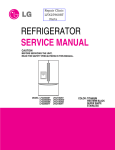
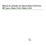
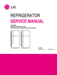
1
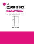
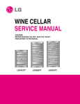
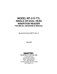
Appliance 911 Seabreeze
REFRIGERATOR
SERVICE MANUAL
CAUTION
BEFORE SERVICING THE UNIT,
READ THE SAFETY PRECAUTIONS IN THIS MANUAL.
MODEL: LRFD25850SB
COLOR:WESTERN BLACK
CONTENTS
SAFETY PRECAUTIONS ....................................................................................................................................................... 2
1. SPECIFICATIONS............................................................................................................................................................... 3
2. PARTS IDENTIFICATION ................................................................................................................................................... 4
3. DISASSEMBLY................................................................................................................................................................ 5-8
REMOVING AND REPLACING REFRIGERATOR DOORS ...............................................................................................5
DOOR .............................................................................................................................................................................. 6-7
TO REMOVE THE DISPENSER .........................................................................................................................................7
DOOR ALIGNMENT ............................................................................................................................................................7
FAN AND FAN MOTOR ...................................................................................................................................................... 8
DEFROST CONTROL ASSEMBLY .................................................................................................................................... 8
LAMP .................................................................................................................................................................................. 8
CONTROL BOX-REFRIGERATOR .................................................................................................................................... 8
MULTI DUCT ...................................................................................................................................................................... 8
4. ADJUSTMENT............................................................................................................................................................... 9-10
COMPRESSOR .................................................................................................................................................................. 9
PTC-STARTER ................................................................................................................................................................... 9
OLP (OVERLOAD PROTECTOR).....................................................................................................................................10
TO REMOVE THE COVER PTC .......................................................................................................................................10
5. CIRCUIT DIAGRAM .......................................................................................................................................................... 11
6. TROUBLESHOOTING................................................................................................................................................. 12-17
COMPRESSOR AND ELECTRIC COMPONENTS.......................................................................................................... 12
PTC AND OLP .................................................................................................................................................................. 13
OTHER ELECTRICAL COMPONENTS ........................................................................................................................... 14
SERVICE DIAGNOSIS CHART ........................................................................................................................................ 15
REFRIGERATION CYCLE .......................................................................................................................................... 16-17
7. OPERATION PRINCIPLE & REPAIR METHOD OF ICEMAKER .............................................................................. 18-21
8. DESCRIPTION OF FUNCTION & CIRCUIT OF MICOM ........................................................................................... 22-33
9. EXPLODED VIEW & REPLACEMENT PARTS LIST ..................................................................................................... 34-
SAFETY PRECAUTIONS
Please read the following instructions before servicing your
refrigerator.
7. Close the top door before opening the bottom door.
Otherwise, you might hit your head when you stand up.
1. Check the refrigerator for current leakage.
2. To prevent electric shock, unplug before servicing.
8. When tilting the refrigerator, remove any materials on
the refrigerator, especially the thin plates (ex. glass
shelf or books.)
3. Always check line voltage and amperage.
4. Use standard electrical components.
5. Don't touch metal products in the freezer with wet
hands. This may cause frostbite.
9. When servicing the evaporator, wear cotton gloves.
This is to prevent injuries from the sharp evaporator
fins.
6. Prevent water from spiling onto electric elements or the
machine parts.
10. Service on the refrigerator should be performed by a
qualified technician. Sealed system repair must be
performed by a CFC certified technician.
-2-
1. SPECIFICATIONS
21 cu. ft. / 25 cu. ft.
ITEMS
ITEMS
SPECIFICATIONS
SPECIFICATIONS
DOOR DESIGN
Side Rounded
VEGETABLE TRAY
Opaque Drawer Type
DIMENSIONS (inches)
35 3/4 X 30 X 69 3/4 (WXDXH) 21cu.ft
COMPRESSOR
PTC Starting Type
35 3/4 X 34 1/4 X 69 3/4 (WXDXH) 25cu.ft
EVAPORATOR
Fin Tube Type
298 (21cu.ft)
CONDENSER
Wire Condenser
320 (25cu.ft)
REFRIGERANT
R-134a (115 g)
COOLING SYSTEM
Fan Cooling
LUBRICATING OIL
ISO10 (280 ml)
TEMPERATURE CONTROL
Micom Control
DEFROSTING DEVICE
SHEATH HEATER
NET WEIGHT (pounds)
Full Automatic
DEFROSTING SYSTEM
REFRIGERATOR
60 W (2EA)
FREEZER
60 W (1EA)
LAMP
Heater Defrost
DOOR FINISH
Embossed Metal, VCM, Stainless
HANDLE TYPE
Bar
INNER CASE
ABS Resin
INSULATION
Polyurethane Foam
-3-
2. PARTS IDENTIFICATION
Filter
Dairy Bin
Refrigerator Light
Egg Box
Shelves
Modular Door Bins
Modular Door Bin
Wine Holder
Optibin Crisper
Keeps fruits and
vegetable fresh
and crisp
Modular Door Bin
Cover Front
Glide N Serve
Customcube
Icemaker
Pull out Drawer
Ice Bin
Durabase
Freezer
Door Rack
(LRFD25850** Only)
Divider
-4-
3. DISASSEMBLY
3-1 REMOVING AND REPLACING REFRIGERATOR DOORS
● Removing
Refrigerator Door
w CAUTION: Before you begin, unplug the refrigerator. Remove food and bins from doors.
u Left Door
1. Disconnect water supply tube by pushing back on the disconnect ring (4).
2. Open door. Loosen top hinge cover screw (1).
Use flat tip screwdriver to pry back hooks on front underside of cover (3). Lift up cover.
3. Disconnect door switch wire harness (2). Remove cover.
4. Attach the tube on the door with door.
5. Pull out the tube.
6. Disconnect the three wire harnesses (5). Remove the grounding screw (6).
7. Rotate hinge lever (7) counterclockwise and remove. Lift top hinge (8) free of hinge lever latch (9).
w CAUTION: When lifting hinge free of latch, be careful that door does not fall forward.
8. Lift door up from middle hinge pin (10) and remove door.
9. Place door, inside facing up, down onto a non-scratching surface.
u Right Door
1. Open door. Loosen top hinge cover screw (1). Lift up cover (3).
2. Disconnect door switch wire harness (2). Remove cover.
3. Disconnect wire harness (5). Remove the grounding screw (6).
4. Rotate hinge lever (7) clockwise and remove. Lift top hinge (8) free of hinge lever latch (9).
w CAUTION: When lifting hinge free of latch, be careful that door does not fall forward.
5. Lift door up from middle hinge pin (10) and remove door.
6. Place door, inside facing up, down onto a non-scratching surface.
1
3
3
2
1
7
4
6
5
8
9
2
6
7
5
8
9
4
-5-
● Door
Gasket Replacement
1. Insert gasket bracket clips
1) Insert gasket bracket edge beneath door frame edge.
2) Turn upper gasket bracket spring so that the spring
ends are in the door channel.
3) Push in clip until you hear it snap securely into place.
3-2 DOOR
● Door
Gasket Removal
1. Remove door frame cover
Starting at top of cover and working down, snap cover
out and away from door.
Gasket
Bracket Clip
Frame Cover
Handle
Spring
Door
Frame
Correct
Incorrect
Figure 1
Figure 4
2. Remove gasket bracket clips
There are two clips on each door. Start bracket removal
near one of the middle clips.
1) Pull gasket back to expose gasket bracket clip and
door frame.
2) Insert a flat tip screwdriver into seam between gasket
bracket and door frame and pry back until clips snaps
out.
3) Continue prying back along seam until all clips snap
out.
Door
Frame
4) Push in remaining two clips until you hear each snap
securely into place.
Note: Make sure that no part of gasket bracket edge
protrudes from beneath door frame edge.
2. Insert gasket into channel
1) Snap gasket assembly into the door bracket.
<Inserting the Gasket Assembly into the Bracket Door>
Gasket
Bracket Clip
Flat Tip
Screwdriver
Correct
Gasket
Bracket
Figure 2
3. Remove gasket
Pull gasket free from gasket channel on the three
remaining sides of door.
Incorrect
Figure 5
Figure 3
-6-
2. Pry off cover dispenser.
2) Press gasket into channels on the three remaining
sides of door.
Figure 6
Figure 9
3. Replace door frame cover
Starting at top of cover and working down, snap cover
back into door.
Disconnect wire harness.
3. Replace cover dispenser in opposite manner and order
of removal.
3-4 DOOR ALIGNMENT
If the space between your doors is uneven, follow the
instructions below to align the doors:
1. With one hand, lift up the door you want to raise at
middle hinge.
2. With other hand, use pliers to insert snap ring as shown.
3. Insert additional snap rings until the doors are aligned.
(Three snap rings are provided with unit.)
Figure 7
3-3 TO REMOVE THE DISPENSER
1. Use fiat tip screwdriver to pry back hooks on botton
underside of cover dispenser.
Figure 8
Figure 10
-7-
3-5 FAN AND FAN MOTOR
3-7-1 Refrigerator Compartment Lamp
1. Remove the freezer shelf. (If your refrigerator has an
icemaker, remove the icemaker first)
2. Remove the plastic guide for slides on left side by
unscrewing phillips head screws.
3. Remove the grille by removing one screw and pulling the
grille forward.
4. Remove the Fan Motor assembly by loosening 2 screws
and disassembling the shroud.
5. Pull out the fan and separate the Fan Motor and Bracket.
1. Unplug the power cord from the outlet.
2. Remove refrigerator shelves.
3. Release the hooks on both ends of the lamp shield and
pull the shield downward to remove it.
4. Turn the lamp counterclockwise.
5. Assembly is the reverse of disassembly. Replacement
bulb must be the same specification as the original
(Max. 60 W2EA).
FAN MOTOR
BRACKET
MOTOR
Figure 15
FAN
3-7-2 Freezer Compartment Lamp
1. Unplug refrigerator or disconnect power.
2. Reach behind light shield to remove bulb.
3. Replace bulb with a 60-watt appliance bulb.
4. Plug in refrigerator or reconnect power.
Figure 11
GRILLE
3-8 CONTROL BOX-REFRIGERATOR
1. First, remove all shelves in the refrigerator, than remove
the Refrigerator control Box by loosening 2 screws.
3-6 DEFROST CONTROL ASSEMBLY
Defrost Control assembly consists of Defrost Sensor and
FUSE–M.
The Defrost Sensor works to defrost automatically. It is
attached to the metal side of the Evaporator and senses its
temperature. At 72°C, it turns the Defrost Heater off.
Fuse-M is a safety device for preventing over-heating of
the Heater when defrosting.
1. Pull out the grille assembly. (Figure 12)
2. Separate the connector with the Defrost Control
assembly and replace the Defrost Control assembly
after cutting the Tie Wrap. (Figure 13)
GRILLE ASSEMBLY
CONTROL BOX
COVER LAMP
Figure 16
DEFROST-CONTROL
ASSEMBLY
2. Remove the Refrigerator Control Box by pulling it
downward.
3. Disconnect the lead wire on the right position and
separate the lamp sockets.
3-9 MULTI DUCT
Figure 12
1. Remove the upper and
lower Caps by using a flat
screwdriver, and remove 2
screws. (Figure 17)
Figure 13
3-7 LAMP
2. Disconnect the lead wire
on the bottom position.
Figure 17
Figure 14
-8-
4. ADJUSTMENT
4-2-3 PTC-Applied Circuit Diagram
Method for the Motor
4-1 COMPRESSOR
● Starting
4-1-1 Role
The compressor intakes low temperature and low pressure
gas from the evaporator of the refrigerator and compresses
this gas to high-temperature and high-pressure gas. It then
delivers the gas to the condenser.
OVERLOAD PROTECTOR
N
4-1-2 Composition
The compressor includes overload protection. The PTC
starter and OLP (overload protector) are attached to the
outside of the compressor. Since the compressor is
manufactured to tolerances of 1 micron and is hermetically
sealed in a dust and moisture-free environment, use
extreme caution when repairing it.
C
4
PTC
6
S
L1
2
5
PTC STARTER
4-1-3 Note for Usage
(1) Be careful not to allow over-voltage and over-current.
(2) If compressor is dropped or handled carelessly, poor
operation and noise may result.
(3) Use proper electric components appropriate to the
Particular Compressor in your product.
(4) Keep Compressor dry.
If the Compressor gets wet (in the rain or a damp
environment) and rust forms in the pin of the Hermetic
Terminal, poor operation and contact may result.
(5) When replacing the Compressor, be careful that dust,
humidity, and soldering flux don’t contaminate the inside
of the compressor. Contamination in the cylinder may
cause noise, improper operation or even cause it to
lock up.
COMPRESSOR
MOTOR
M
M
S
SEALED
TERMINAL
Resistance Starter Capacitor Running
Figure 18
4-2-4 Motor Restarting and PTC Cooling
(1) It requires approximately 5 minutes for the pressure to
equalize before the compressor can restart.
(2) The PTC device generates heat during operation.
Therefore, it must be allowed to cool before the
compressor can restart.
4-2-5 Relation of PTC-Starter and OLP
(1) If the compressor attempts to restart before the PTC
device is cooled, the PTC device will allow current to
flow only to the main winding.
(2) The OLP will open because of the over current
condition. This same process will continue (3 to 5
times) when the compressor attempts to restart until
the PTC device has cooled. The correct OLP must be
properly attached to prevent damage to the
compressor.
Parts may appear physically identical but could have
different electrical ratings. Replace parts by part
number and model number. Using an incorrect part
could result in damage to the product, fire, injury, or
possibly death.
4-2 PTC-STARTER
4-2-1 Composition of PTC-Starter
(1) PTC (Positive Temperature Coefficient) is a no-contact
semiconductor starting device which uses ceramic
material consisting of BaTiO3.
(2) The higher the temperature is, the higher the resistance
value. These features are used as a starting device for
the Motor.
4-2-6 Note for Using the PTC-Starter
(1) Be careful not to allow over-voltage and over-current.
(2) Do not drop or handle carelessly.
(3) Keep away from any liquid.
If liquid such as oil or water enters the PTC,
PTC materials may fail due to breakdown of their
insulating capabilities.
(4) If the exterior of the PTC is damaged, the resistance
value may be altered. This can cause damage to the
compressor and result in a no-start or hard-to-start
condition.
(5) Always use the PTC designed for the compressor and
make sure it is properly attached to the compressor.
Parts may appear physically identical but could have
different electrical ratings. Replace parts by part
number and model number. Using an incorrect part
could result in damage to the product, fire, injury, or
possibly death.
4-2-2 Role of PTC-Starter
(1) The PTC is attached to the Sealed Compressor and is
used for starting the Motor.
(2) The compressor is a single-phase induction motor.
Durign the starting operation, the PTC allows current
flow to both the start winding and main winding.
-9-
4-3 OLP (OVERLOAD PROTECTOR)
4-4 TO REMOVE THE COVER PTC
4-3-1 Definition of OLP
(1) OLP (OVERLOAD PROTECTOR) is attached to the
Compressor and protects the Motor by opening the
circuit to the Motor if the temperature rises and
activating the bimetal spring in the OLP.
(2) When high current flows to the Compressor motor, the
Bimetal works by heating the heater inside the OLP,
and the OLP protects the Motor by cutting off the
current flowing to the Compressor Motor.
4-3-2 Role of the OLP
(1) The OLP is attached to the Sealed Compressor used
for the Refrigerator. It prevents the Motor Coil from
being started in the Compressor.
(2) For normal operation of the OLP, do not turn the Adjust
Screw of the OLP in any way.
(2) Disconnect two housing upper side of comp connected
in.
(OVERLOAD PROTECTOR cross section)
12345678
330 FBYY
Electrical
characteristics
part number
-S1 BOX98
Customer part
number
Lot code/
date code
Physical
termination
part number
(1) Remove the Cover Back M/C.
Part
No.
Name
(3) Loosen two screws on comp base.
Base, phenolic
(UL 94 V-0 rated)
Movable arm support, plated steel
Stationary contact support,
plated steel
Heater support, plated steel
Heater, resistance alloy
Disc, thermostatic alloy
Movable arm, spring temper
copper alloy
Contact, movable, silver on copper
Contact, stationary, silver on copper
Slug, plated steel
Cover, polyester
(UL 94 V -0 rated)
Pin connector, plated copper alloy
(To engage 2.33/2.66 mm dia. pin)
1
2
3
Figure 19
(4) Use a L-shaped flap tool to pry off the cover.
(5) Assembly in reverse order of disassembly.
- 10 -
5. CIRCUIT DIAGRAM
- 11 -
6. TROUBLESHOOTING
6-1 COMPRESSOR AND ELECTRIC COMPONENTS
1
Power Source.
YES
Remove PTC-Starter
from Compressor and
measure voltage
between Terminal C of
Compressor and
Terminal 5 or 6 of PTC.
(Rated Voltage
±10%)?
No Voltage.
OLP disconnected?
2
YES
Replace OLP.
NO
5
Check connection
condition.
Reconnect.
Applied voltage isn't
in acceptable range.
(115V ±10%)
Advise customer that
power supply needs to be
checked by an electrician.
The range of resistance is between 1~50Ω(ok)
Check
resistance of
Motor
Compressor.
Check resistance
between M-C, S-C and
M-S in Motor
Compressor.
3
Check
resistance of
PTC-Starter.
Check resistance of
two terminals in
PTC-Starter.
Reference Page12.
4
Check OLP.
Check resistance of two
terminals in OLP.
Reference Page12.
5
Check
starting state.
Check the power supply
under load.
(Compressor attempting
to re-start after being off
for 5 minutes).
2
5
Open or short
Replace
Compressor.
Supply
voltage rating
with ±10%.
YES
3
Did
compressor
start?
4
YES
NO
NO
- 12 -
3
5
Compressor
is OK
Replace the
compressor
1
6-2 PTC AND OLP
Separate PTC-Starter
from Compressor and
measure resistance
between No. 5 and 6
of PTC-Starter with a
Tester.
(Figure 20)
Observation value is
115V/60Hz : 6.8Ω±30%
The resistance value
is 0Ω (short) or
∞ (open).
Shows continuity
Separate OLP from
Compressor and check
resistance value
between two terminals
Open
of OLP with a Tester.
(Figure 21)
Check another
electric component.
Replace OLP.
5
6
Normal operation of
Compressor is
impossible or poor.
Figure 20
- 13 -
Figure 21
Replace PTCStarter.
6-3 OTHER ELECTRICAL COMPONENTS
▼ Not cooling at all
Compressor
doesn't run.
Check for open short or
incorrect resistance readings
in the following components
Cause
a. Starting devices
Short, open, or broken.
b. OLP
Poor contact
or shorted.
c. Compressor coil
Coil open or shorted.
d. Wiring harness
Poor contact
or shorted.
Replace
indicated component.
▼ Poor cooling performance
Compressor runs
poorly.
Fan motor
doesn't run.
Check starting
voltage.
Low voltage.
Advise customer that
the Power supply
needs to be checked
by an electrician.
Check voltage at
starting devices.
Poor or broken or
open contact.
Replace
indicated component.
Check current flowing
in sub-coil of
Compressor.
Shorted.
Check rating of OLP.
Lack of capacity.
Check wiring circuit.
Wire is open or
shorted.
Coil is shorted
or open.
Check Fan Motor.
Heavy frost buildup on
EVAPORATOR.
Replace
indicated component.
Check current flow in
the following
components:
Sensor
Fuse-M
Check current flow in
the Defrost Heater.
- 14 -
Open.
Replace
indicated component.
Open.
Replace
Defrost Heater.
6-4 SERVICE DIAGNOSIS CHART
COMPLAINT
POINTS TO BE CHECKED
REMEDY
No Cooling.
• Is the power cord unplugged from the outlet?
• Check if the power switch is set to OFF.
• Check if the fuse of the power switch is shorted.
• Measure the voltage of the power outlet.
• Plug into the outlet.
• Set the switch to ON.
• Replace the fuse.
• If the voltage is low, correct the wiring.
Cools poorly.
• Check if the unit is placed too close to the wall.
• Check if the unit is placed too close to the stove,
gas cooker, or in direct sunlight.
• Is the ambient temperature too high or
the room door closed?
• Check if food put in the refrigerator is hot.
• Did you open the door of the unit too often
or check if the door is sealed properly?
• Check if the Control is set to Warm position.
• Place the unit about 4 inches (10 cm) from the wall.
• Place the unit away from these heat sources.
• Is food placed in the cooling air outlet?
• Check if the control is set to colder position.
• Is the ambient temperature below 41°F(5°C)?
• Place foods in the high-temperature section.
(front part)
• Set the control to Recommended position.
• Set the control to Warm position.
Condensation or ice
forms inside
the unit.
• Is liquid food sealed?
• Check if food put in the refrigerator is hot.
• Did you open the door of the unit too
often or check if the door is sealed properly?
• Seal liquid foods with wrap.
• Put in foods after they have cooled down.
• Don't open the door too often and close
it firmly.
Condensation forms
in the Exterior Case.
• Check if the ambient temperature and humidity
of the surrounding air are high.
• Is there a gap in the door gasket?
• Wipe moisture with a dry cloth. It will disappear
in low temperature and humidity.
• Fill up the gap.
There is abnormal
noise.
• Is the unit positioned in a firm and even place?
• Adjust the Leveling Screw, and position the
refrigerator in a firm place.
• Remove the objects.
Food in the
Refrigerator
is frozen.
• Are any unnecessary objects placed
in the back side of the unit?
• Check if the Drip Tray is not firmly fixed.
• Check if the cover of the compressor enclosure
in the lower front side is taken out.
Door does not
close well.
• Check if the door gasket is dirty with
an item like juice.
• Is the refrigerator level?
●
• Put in foods after they have cooled down.
• Don't open the door too often and close
it firmly.
• Set the control to Recommended position.
• Fix the Drip Tray firmly in the original position.
• Place the cover in its original position.
• Clean the door gasket.
• Is there too much food in the refrigerator?
Ice and foods
smell unpleasant.
• Lower the ambient temperature.
• Check if the inside of the unit is dirty.
• Are foods with a strong odor unwrapped?
• The unit smells of plastic.
• Position in a firm place and level the
Leveling Screw.
• Make sure food stored in shelves does not prevent
the door from closing.
• Clean the inside of the unit.
• Wrap foods that have a strong odor.
• New products smell of plastic, but this
will go away after 1-2 weeks.
Other possible problems:
Check if frost forms in
the freezer.
Not
defrosting
Check Components
of the defrosting
circuit.
Check the
refrigeration system.
The system
is faulty.
Perform sealed
system repair.
Check the
Thermistor.
The operation of
the Thermistor is
incorrect.
- 15 -
Replace the
Thermistor.
6-5 REFRIGERATION CYCLE
▼ Troubleshooting Chart
CAUSE
STATE OF
THE UNIT
STATE OF THE
EVAPORATOR
TEMPERATURE
OF THE
COMPRESSOR
REMARKS
LEAKAGE
CLOGGED BY DUST
PARTIAL
LEAKAGE
Freezer
compartment and
Refrigerator don't
cool normally.
Low flowing sound of
Refrigerant is heard and
frost forms in inlet only.
A little higher
than ambient
temperature.
• Refrigerant level is low due
• to a leak.
• Normal cooling is possible by
• restoring the normal amount of
• refrigerant and repairing the leak.
COMPLETE
LEAKAGE
Freezer
compartment and
Refrigerator don't
cool normally.
Flowing sound of refrigerant
is not heard and frost isn't
formed.
Equal to ambient
temperature.
• No discharging of Refrigerant.
• Normal cooling is possible by
• restoring the normal amount of
• refrigerant and repairing the leak.
PARTIAL
CLOG
Freezer
compartment and
Refrigerator don't
cool normally.
Flowing sound of refrigerant
is heard and frost forms
in inlet only.
A little higher
than ambient
temperature.
• Normal discharging of the
• refrigerant.
• The capillary tube is faulty.
WHOLE
CLOG
Freezer
Flowing sound of refrigerant
compartment and
is not heard and frost isn't
Refrigerator don't cool. formed.
Equal to ambient
temperature.
• Normal discharging of the
• Refrigerant.
Cooling operation
stops periodically.
Flowing sound of refrigerant
is not heard and frost melts.
Lower than
ambient
temperature.
• Cooling operation restarts
• when heating the inlet of the
• capillary tube.
COMPRESSION
Freezer and
Refrigerator
don't cool.
Low flowing sound of
refrigerant is heard and
frost forms in inlet only.
A little higher
than ambient
temperature.
• Low pressure at high side
• of compressor due to low
• refrigerant level.
NO COMPRESSION
No compressing
operation.
Flowing sound of refrigerant
is not heard and there is
no frost.
Equal to ambient
temperature.
• No pressure in the high
• pressure part of the
• compressor.
MOISTURE
CLOG
DEFECTIVE
COMPRESSION
- 16 -
6-5-1 SEALED SYSTEM DIAGNOSIS
“Not Cooling” Complaint
All components operating, No airflow problems, Not frosted up as a defrost problem
problem has been isolated to sealed system area
Frost
Pattern?
Partial
None
Equalization
Test
Equalization
Test
Very Fast
Very Slow
Very Slow
Very Fast
Fast
Inefficient
Compressor
Partial
Restriction
Complete
Restriction
Condenser
Temperature
Cap Tube
Sound
Hotter than Normal
Faint
Room Temperature
None to Weak
Air/Low Side
Leak
Loss of Change
Compressor Not
Pumping
Trace of Oil
Yes
No
Leak
Undercharge
(The equalization test is trying to restart a compressor using a start kit after it has been operating.)
- 17 -
7. OPERATION PRINCIPLE AND REPAIR METHOD OF ICEMAKER
7-1 OPERATION PRINCIPLE
7-1-1 Operation Principle of IceMaker
Power On
Start Position
Ice Making
Mode
Harvest
Mode
Fill
• Adjusts EJECTOR to Start Position with power on.
• Waits until water becomes cold after starting the
ice making operation.
• Runs MOTOR to drop ice from the tray into the ICE BIN.
• Performs Ice Making Mode after supplying water by operating
the SOLENOID in ICE VALVE.
Park Position
Test Mode
• With the detect lever, checks if the ICE BIN is full.
• To operate LINE and SERVICE, press and hold the Fill Key
for 3 seconds. The ice maker will run through 3 stages:
Harvest
Fill
Icemaking.
1. Turning the Icemaker stop switch off (O) stops the ice making function.
2. Setting the Icemaker switch to OFF and then turning it back on will reset the icemaker control.
Fill Key
Power (On/ Off) Switch
- 18 -
7-2 ICE MAKER FUNCTIONS
7-2-1 Start Position
1. After POWER OFF or Power Outage, check the EJECTOR's position with MICOM initialization to restart.
2. How to check if it is in place:
- Check HIGH/LOW signals from HALL SENSOR in MICOM PIN.
3. Control Method to check if it is in place:
(1) EJECTOR is in place,
- It is an initialized control, so the mode can be changed to ice making control.
(2) EJECTOR isn't in place:
A. If EJECTOR is back in place within 2 minutes with the motor on, it is being initialized. If not, go to Step B.
B. If EJECTOR is back in place within 18 minutes after the heater turns from ON to OFF, it is being initialized. If not, it is
not functioning. Repeat Step B with Heater and Motor off.
7-2-2 Ice Making Mode
1. Ice Making refers to the freezing of supplied water in the ice trays. Complete freezing is assured by measuring the
temperature of the Tray with Ice-Making SENSOR.
2. Ice Making starts after completion of the water fill operation.
3. The Ice Making function is completed when the sensor reaches 19°F(-7°C), 60 to 240 minutes after starting.
4. If the temperature sensor is defective, the ice-making function will be completed in 4 hours.
NOTE : After Icemaker Power is ON, the Icemaker heater will be on for test for 9 sec.
7-2-3 Harvest Mode
1. Harvest (Ice removing) refers to the operation of dropping cubes into the ice bin from the tray when ice-making has
completed.
2. Harvest mode:
(1) The Heater is ON for 30 seconds, then the motor starts.
(2) After performing Step 1 (the Heater is turned OFF), the Ejector will be back in place wthin 18 minutes. (Hall SENSOR
sign = OV). Ice removal is then complete. Then the Ice Maker cycles to the Fill Mode. The water supply fails to start, it
is not functioning. Put the Heater and Motor in the off position. Restart every 2 hours. (Refer to fig.1)
NOTE : If the motor malfunctions and starts before the detect lever rises, MICOM regards the Ice-Removing phase as
completed. Water then starts flowing. To prevent this, MICOM doesn’t switch to water-supply mode, but restarts the iceremoving mode. If this happens 3 times, the motor is malfunctioning and you should stop the loads (Heater, Motor). Then
restart the Ice-Removing mode every 2 hours. (See Step 2 above.)
Ice making sensor temperature is 50°F(10˚C)
or more
Max. 18 minutes
After detect LEVER rises
on
Heater
off
30 sec.
Motor
2 ms
on
Ice removing
completion point
off
10 sec.
Hall IC
5V
0V
<fig1. Harvest mode Process>
- 19 -
7-2-4 Fill / Park Position
1. Once a normal harvest mode has been completed, the water solenoid will be activated.
2. The amount of water is adjusted by pressing the Fill Key repeatedly. This changes the time allowed for fill as illustrated in
the table below.
<Water supply amount TABLE>
STAGE
TIME TO SUPPLY
1
6 sec.
2
6.5 sec.
INDICATIONS
REMARKS
The water amount will vary depending
3
on the water control Switch setting, as
7 sec.
well as the water pressure of the
connected water line.
4
7.5 sec.
5
8 sec.
- 20 -
7-2-5 Function TEST
1. This is a compulsory operation for TEST, SVC, cleaning, etc. It is operated by pressing and holding the Fill Key for 3 seconds.
2. The test works only in the Ice Making Mode. It cannot be entered from the Harvest or Fill mode. (If there is an ERROR, it
can only be checked in the TEST mode.)
3. Caution! If the test is performed before water in the Maker is frozen, the Ejector will pass through the water. When the Fill
mode begins (Stage 4), unless the water supply has been shut off, added water will overflow into the ice bin. If the control
doesn’t operate normally in the TEST mode, check and repair as needed.
4. After water is supplied, the normal CYCLE is followed: ice making → Harvest → Fill → Park Position.
5. Five seconds after Stage 5 is completed, the Ice Maker returns to MICOM control. The time needed to supply water
resets to the pre- test setting.
<Diagnosis TABLE>
STAGE
ITEMS
INDICATOR
1
HEATER
2
MOTOR
3
HALL IC I
(detection of
position)
4
VALVE
5
HALL IC II
(detection of fullfilled Ice)
6
Reset
REMARKS
Five seconds after heater starts, heater will
go off if temperature recorded by sensor is
10°C or lever is in up position.
Five seconds after heater starts, you can
confirm that motor is moving.
You can confirm Hall Ic detection of position.
Two seconds after detection of initial
position, you can confirm that valve is on.
You can check whether hall is sensing Full
ice condition. (If there is a full-filled error, the
fifth LED is not on.)
Five seconds after fifth stage is completed,
the icemaker resets to initial status.
Return to Status prior to
TEST MODE
7-3 DEFECT DIAGNOSIS FUNCTION
7-3-1 ERROR CODES shown on Ice Maker water supply control panel
NO
DIVISION
1
Normal
2
Ice-Making
Sensor
malfunction
3
Ice Maker Kit
malfunction
INDICATOR
CONTENTS
REMARKS
None
Display switch
operates properly
Open or short-circuited wire
Make sure that the wire
on each sensor is
connected.
When ejector blades don’t reach
park position over 18 minutes after
Harvest Mode starts.
Check
HALL IC/MOTOR/
HEATER/RELAY
Mark time to
supply
ERROR indicators in table can be checked only in TEST mode.
- 21 -
8. DESCRIPTION OF FUNCTION & CIRCUIT OF MICOM
8-1 FUNCTION
8-1-1 Function
1. When the appliance is plugged in, it is set to 37°F for Refrigerator and 0°F for freezer.
You can adjust the Refrigerator and the Freezer control temperature by pressing the ADJUST button.
2. When the power is initially applied or restored after a power failure, it is automatically set to “37” & “0”.
8-1-2 How to Toggle the Display between °F & °C
1. The display temperature mode can be changed from °F to °C or °C to °F by pressing and holding the FRZ TEMP and the
REF TEMP keys at the same time for over one second.
2. The initial setting is °F. Whenever the mode is changed, the LED lights are changed.
8-1-3 Lock function (dispenser and display button lock)
1. When the refrigerator is first turned on, the buttons are not locked. The display panel shows the padlock
unlocked icon.
2. To lock the display, the dispenser, and the control panel, press
LOCK CONTROL
and hold the LOCK button for 3 seconds. The locked padlock
LOCK
icon is displayed with the word "LOCK" printed beside it.
DISPENSER & BUTTON DISPENSER & BUTTON
3. The LOCK button is the only control feature that remains active
in the locked state. The buzzer sound, other control buttons,
and the dispenser are deactivated.
Ex) In selecting
Ex) In selecting
4. To release from the locked state, press and hold the LOCK
"LOCK"
"LOCK" again
button again for 3 seconds.
8-1-4 Filter condition display function
1. There is a replacement indicator light for the water
filter cartridge on the dispenser.
2. Water filter needs replacement once six months or
about 28,000 seconds of using water filter.
3. Water filter light and “FILTER RESET HOLD 3 SECS”
text turn on to tell you need to replace the filter soon.
4. After replace the filter, press and hold the lock button
more than 3 seconds.
Then water filter light and “FILTER RESET HOLD 3
SECS” text turn off with reset status.
Classification
In initial Power On
/ Filter RESET
Filter Status
Display
8-1-5 Express freezing selection
Please select this function for quick freezing.
• Function is repeated following below whenever pressing Express FRZ button.
• Expressing freezer function automatically turns off after a fixed time passes.
- 22 -
Replace indicator
light on
FILTER RESET
HOLD 3SECS
EXPRESS FRZ
8-1-6 CONTROL OF FREEZER FAN MOTOR
1. Freezer fan motor has high and standard speeds.
2. High speed is used at power-up, for express freezing, and when refrigerator is overloaded.
Standard speeds is used for general purposes.
3. To improve cooling speed, the RPM of the freezer fan motor change from normal speed to high.
4. High speed (2700RPM) : Initial power on or load corresponding operation, express freezing.
Normal speed (2400RPM) : General working conditions.
5. Fan motor stops when refrigerator or freezer door opens.
8-1-7 EXPRESS FREEZING
1. The purpose of this function is to intensify the cooling speed of freezer and to increase the amount of ice.
2. Whenever selection switch is pressed, selection/release, the LED will turn ON or OFF.
3. If there is a power outage and the refrigerator is powered on again, EXPRESS FREEZING will be canceled.
4. To activate this function, press the Express Freezing key and the LED will turn ON. This function will remain activated for
24 hrs. The first three hours the compressor and Freezer Fan will be ON. The next 21 hours the freezer will be controlled
at the lowest temperature. After 24 hours or if the Express Freezing key is pressed again, the freezer will return to its
previous temperature.
5. During the first 3 hours:
(1) Compressor and freezer fan (HIGH RPM) run continuously.
(2) If a defrost cycle begins during the first 90 minutes of Express Freezing, the Express Freeze cycle will complete its
cycle after defrosting has ended.
If the defrost cycle begins when Express Freeze has run for more than 90 minutes, Express Freeze will run for two
hours after the defrost is completed.
(3) If EXPRESS FREEZING is pressed during defrost, EXPRESS FREEZING LED is on but this function will start seven
minutes after defrost is completed and it shall operate for three hours.
(4) If EXPRESS FREEZING is selected within seven minutes after compressor has stopped, the compressor (compressor
delays seven minutes) shall start after the balance of the delay time.
(5) The fan motor in the freezer compartment runs at high speed during EXPRESS FREEZING .
6. For the rest of the 21 hours, the freezer will be controlled at the lowest temperature.
8-1-8 REFRIGERATOR LAMP AUTO OFF
1. To avoid heat damage caused by the lamp, it is turned off automatically when the refrigerator door is open for more than 7
minutes.
8-1-9 Alarm for Open Door
1. This feature sounds a buzzer when the freezer or refrigerator door is not closed within 1 minute after it is opened.
2. One minute after the door is opened, the buzzer sounds three times each for 1/2 seconds. These tones repeat every 30
seconds.
3. The alarm is cancelled when the freezer or the refrigerator is closed while the buzzer sounds.
Freezer Door Closed
or Refrigerator
Door
Open
Closed
Open
Closed
3 Times
3 Times
3 Times
3 Times
Buzzer
Within 1 min.
1 min.
- 23 -
30 sec
30 sec
30 sec
8-1-10 Buzzer Sound
When the button on the front Display is pushed, a Ding~ Dong~ sound is produced.
(Refer to the Buzzer Circuit 8-2-4 No. 3)
8-1-11 Defrosting (removing frost)
1. Defrosting starts each time the COMPRESSOR running time reaches 7 hours.
2. For initial power on or for restoring power, defrosting starts when the compressor running time reaches 4 hours.
3. Defrosting stops if the sensor temperature reaches 46.4°F(8°C) or more. If the sensor doesn’t reach 46.4°F(8°C) in
2 hours, the defrost mode is malfunctioning. (Refer to the defect diagnosis function, 8-1-14.)
4. Defrosting won’t function if its sensor is defective (wires are cut or short circuited)
8-1-12 Filter Replacement Indication
1. In 6 months after the UNIT (refrigerator) is power on, or after 28,000 seconds of dispenser use, the water filter Indicator
LED will be ON.
2. When the water filter indicator LED is illuminated, you should change the water filter. After this, you must press the water
filter button for three seconds and you will hear a ding-dong sound.
The LED will be OFF. This operation will indicate that the UNIT is reset to its initial conditions, so this process is restarted.
8-1-13 Electrical Parts Are Turned On Sequentially
Electrical parts such as COMP, defrosting heater, freezer FAN, etc. are turned on in the following order to prevent noise and
parts damage. Several parts are started at the same time at initial power on and are turned off together when TEST is
completed.
OPERATING
Initial power on
Temperature of Defrosting
Sensor is 113°F(45°C) or
more (when unit is newly
purchased or when moved)
Temperature of defrosting
sensor is lower than
113°F(45°C)
(when power cuts, SERVICE)
ORDERS
POWER in 1/2 second COMP
ON
ON
POWER
ON
in 1/2 second
in 1/2 second
Reset to normal operation
from TEST MODE
Total load
OFF
COMP
ON
in 7 minute
in 1/2 second
Freezer FAN
ON
Defrosting
heater ON
in 10 second
in 1/2 second
Freezer FAN
ON
COMP
ON
in 1/2 second
Defrosting
heater OFF
Freezer FAN
ON
8-1-14 How to show the display ON & OFF
The display can be changed from on to off mode or off to on mode by pressing and holding the EXPRESS FRZ and FRZ
TEMP buttons at the same time for over five seconds.
- 24 -
8-1-15 Defect Diagnosis Function
1. Automatic diagnosis makes servicing the refrigerator easy.
2. When a defect occurs, the buttons will not operate; but the tones. such as ding. will sound.
3. When the defect CODE removes the sign, it returns to normal operation (RESET).
4. The defect CODE shows on the Refrigerator and Freezer Display.
ERROR CODE on display panel
ERROR CODE
NO
ITEM
1
Failure of freezer
sensor
Er
FS
Cut or short circuit wire
2
Failure of
Refrigerator sensor
Er
rS
Cut or short circuit wire
3
Failure of defrost
sensor
4
Failure of Room
Temperature
sensor
5
Failure of defrost
mode
6
Failure of BLDC
Fan Motor at
Freezing
Compartment.
Er
CONTENTS
dS
Cut or short circuit wire
When Display check mode
Er
Er
REMARKS
Inspect Connecting wires
on each sensor
Cut or short circuit wire
dH
When defrost sensor
doesn’t reach 46°F within 2
hours after starting defrost.
Snapping of defrost heater
or Temperature fuse, pullout of connector (indicated
minimum 2 hours after
failure occurs)
FF
If there is no fan motor
signal for more than 65sec
in operation fan motor
Poor motor, hooking to
wires of fan, contact of
structures to fan, snapping
or short circuit of Lead wires
Note 1) Freezer room notch temperature display and refrigerator room notch temperature display (Failure code
indication part) are normally indicated in abnormal ambient sensor, and “Er” indicated on the amvient
temperature display.
✽ LED check function: If simultaneously pressing express freezer button and freezing temperature adjustment
button for a second, display LED graphics on. If releasing the button, the LED graphic
displays the previous status.
- 25 -
8-1-16 TEST Mode
1. The Test mode allows checking the PCB and the function of the product as well as finding out the defective part in case of
an error.
2. The test mode is operated by pressing two buttons at Display panel.
3. While in the test mode, the function control button is not recognized, but the recognition tone (beep~) sounds.
4. After exiting the test mode, be sure to reset by unplugging and then plugging in the appliance.
5. If an error, such as a sensor failure, is detected while in the test mode, the test mode is cleared and the error code is
displayed.
6. While an error code is displayed, the test mode will not be activated.
MODE
MANIPULATION
CONTENTS
REMARKS
TEST1
Push Express Freezing
Key and LOCK KEY at the
same time for 3 seconds
OR Push TEST S/W(on
the main Board) once.
1) Continuous operation of the
COMPRESSOR and the Freezer fan
2) Stepping DAMPER OPEN
3) Defrosting HEATER OFF
4) DISPLAY LED all ON
TEST2
Push Express Freezing
Key and LOCK KEY at the
same time for 3 seconds
in TEST MODE 1 OR
Push TEST S/W once in
TEST MODE 1
1) Continuous operation of the
COMPRESSOR and the Freezer fan
2) Stepping DAMPER CLOSE
3) Defrosting HEATER OFF
4) DISPLAY LED shows no. 2
TEST3
Push Express Freezing
Key and LOCK KEY at the
same time for 3 seconds
in TEST MODE 2 OR
Push TEST S/W once in
TEST MODE 2
1) COMPRESSOR and the Freezer fan
OFF
2) Stepping DAMPER CLOSE
3) Defrosting HEATER ON
4) DISPLAY LED shows no. 3
Reset if the
Temperature of the
Defrosting Sensor is
46°F(8°C) or more.
Reset
Push Express Freezing
Key and LOCK KEY at the
same time for 3 seconds
in TEST MODE 3 OR
Push TEST S/W once in
TEST MODE 3
Reset to the previously setting
Before TEST MODE.
The compressor will
Start after a 7-minute
Delay.
* Freezer Fan RPM Variable Check:
In case the freezer fan is in operation when the express freezer button and freezing temp. button. Control are pressed for
more than one second at the same time freezer fan RPM changes. (for example if high speed, to normal speed or if
normal speed, to high speed for 30 seconds)
After 30 seconds, it turns to its original RPM.
* Demonstration MODE:
1. When the express freeze button and the refrigerator temperature control button are pushed at the same time and hold
for 5 seconds or longer, it converts to demonstration mode.
2. The Display shows the Demo graphic.
3. In this status, all Loads are off (Compressor / Fan / Damper / Heater)
(Even is Demonstration Mode, the refrigerator Lamp automatic off function warks normally and can be demonstrated)
4. Exit the Demo mode and reset the Display by pressing the Freezer Temp. Control button and the Refrigerator Temp.
Control button for 3 seconds or longer.
- 26 -
8-2 PCB FUNCTION
8-2-1 Power Circuit
1. Power is supplied to the control board at pin7 and 9 od connector #1.
- 27 -
8-2-2 Load / Buzzer Drive & Open Door Detection Circuit
1. Load Drive Condition Check
To measure outputs of the control board, check voltages between the pins for the following components:
Circuit
Pin Number
Pin Number
Output Voltage
Compressor
Con2 pin11
Con1 pin1
115 VAC
Condenser fan
Con2 pin11
Con1 pin1
115 VAC
Defrost heater
Con2 pin9
Con1 pin1
115 VAC
F,R-lamp
Con2 pin,3.5
Con1 pin1
115 VAC
Water valve
Con2 pin7
Con1 pin1
115 VAC
Dew heater
Con2 pin3
Con1 pin1
115 VAC
Water valve
Con2 pin1
Con1 pin1
115 VAC
NOTE: When the door of the freezer/refrigerator is left open for 7 minutes or longer, the lamp of the
freezer’refrigerator turns.
2. Fan motor driving circuit (freezing compartment fan)
Pin1 & 2 of con4
MOTOR OFF
2V or less
MOTOR ON
13V~15V
- 28 -
3. Open Door Detection Circuit Check
8-2-3 Temperature Sensor Circuit
Measurement
Location
Freezer/
Refrigerator Door
Pin 4 & 5 of con4 Ref.Door
Pin 5 & 6 of con5 Fre.Door
Closed
0V
Open
5V
TEMPERATURE
RESISTANCE OF FREEZER
SENSOR
RESISTANCE OF REFRIGERATOR &
DEFROST SENSOR & ROOM SENSOR
- 20 ˚C (-4 °F)
22.3 KΩ
77 KΩ
- 15 ˚C (5 °F)
16.9 KΩ
60 KΩ
- 10 ˚C (14 °F)
13.0 KΩ
47.3 KΩ
- 5 ˚C (23 °F)
10.1 KΩ
38.4 KΩ
0 ˚C (32 °F)
7.8 KΩ
30 KΩ
+ 5 ˚C (41 °F)
6.2 KΩ
24.1 KΩ
+ 10 ˚C (50 °F)
4.9 KΩ
19.5 KΩ
+ 15 ˚C (59 °F)
3.9 KΩ
15.9 KΩ
+ 20 ˚C (68 °F)
3.1 KΩ
13 KΩ
+ 25 ˚C (77 °F)
2.5 KΩ
11 KΩ
+ 30 ˚C (86 °F)
2.0 KΩ
8.9 KΩ
+ 40 ˚C (104 °F)
1.4 KΩ
6.2 KΩ
+ 50 ˚C (122 °F)
0.8 KΩ
4.3 KΩ
• The resistance of the SENSOR has a ±5% common difference.
• Measure the resistance of the SENSOR after leaving it for over 3 minutes in the measuring temperature.
This delay is necessary due to sensor response speed.
- 29 -
8-2-4 Refrigeration Compartment Stepping Motor Damper Circuit
A reversible DC motor is used to open and close the damper.
To open the damper, push test button once.
To close the damper, push test button twice.
- 30 -
8-3 TROUBLESHOOTING
PROBLEM
INDICATED BY
POWER
SOURCE is
poor.
1. The whole
DISPLAY
LED/SEVEN
SEGMENT
DISPLAY is off.
2. DISPLAY LED/
SEVEN
SEGMENT
DISPLAY
operates
abnormally
COOLING is
poor.
NO COOLING.
FREEZER
TEMPERATURE
is incorrect
CHECK
CHECKING METHOD
CAUSE
SOLUTION
1. FREEZER/
REFRIGERATOR.
Check if
FREEZER/REFRIGERA
TOR DOOR IS OPEN
and check display.
POWER SOURCE is
poor.
Use boosting TRANS.
2. If LAMP is dim.
Check visually.
Applied voltage error.
Reconnect
CONNECTOR.
3. The connection of the
MAIN PWB
CONNECTOR.
Check connection of
CONNECTOR.
CONNECTOR
connection is poor.
Replace TRANS.
TRANS FUSE is open.
Replace
COMPRESSOR.
COMPRESSOR locked
or blocked.
Replace OLP, PTC.
OLP, PTC is poor.
COMPRESSOR RELAY
is poor.
Replace MAIN PWB.
THE CONNECTING
WIRE is poor.
Check the connection of
the black wire of the
MAIN PWB
CONNECTOR (CON2).
1. If the COMPRESSOR
operate.
USE TEST MODE1
(forced COOLING).
If less than 7 minutes
pass after compressor
shuts off, don’t press the
KEY and wait.
2. If refrigerant is leaking.
Measure the amount of
frost sticking on
EVAPORATOR and the
surface temperature of
the condenser pipe.
Refrigerant leakage.
Replace the leaking part
and replace any lost
refrigerant.
1. If FAN MOTOR
operates.
USE TEST MODE1
(forced COOLING).
FAN MOTOR is poor.
Replace the FAN
MOTOR.
CONNECTING WIRE is
poor.
Certify the MOTOR and
the connection of the
black wire of the MAIN
PWB CONNECTOR
(CON2).
See DEFROSTING is
poor.
2. If DEFROSTING is
normal.
Check the amount of frost DEFROSTING is poor.
sticking on the
EVAPORATOR .
3. If SENSOR is normal.
of the Refrigerator
SENSOR.
SENSOR RESISTANCE
is poor.
Replace SENSOR.
4. Door Line contact.
Check the seal when the
door is closed.
Door liner damaged.
Replace door liner.
- 31 -
PROBLEM
INDICATED BY
COOLING is
poor.
If
REFRIGERATOR
TEMPERATURE
is too low.
DEFROSTIN
G is poor.
NO
DEFROSTING.
CHECK
CHECKING METHOD
CAUSE
SOLUTION
Make sure the DOOR
isattached.
1. If FREEZER
TEMPERATURE is
normal.
Check is FREEZER
TEMPERATURE is too
low.
2. If amount of cool air
from FAN MOTOR is
sufficient.
Make sure that the
amount and speed of cool
air are sufficient by
touching the check
supplied on the
REFRIGERATOR.
FAN MOTOR is poor.
Replace FAN MOTOR.
Passage of cool air is
blocked.
Remove impurities.
EVA frozen.
See DEFROSTING is
poor.
3. Door Line contact.
Check door seal when
door is closed.
Door liner damaged.
Replace Door liner.
1. If HEATER emits heat.
USE TEST MODE3
(forced DEFROSTING).
HEATER disconnection.
Replace HEATER.
TEMPERATURE FUSE
disconnection.
Replace
TEMPERATURE FUSE.
Connection is poor.
Check EVAPORATOR
connection and wire of
MAIN PWB
CONNECTOR.
DEFROST-SENSOR is
poor.
Replace DEFROSTSENSOR.
HEATER RELAY is poor.
Replace RY3 of MAIN
PWB.
DRAIN PIPE is blocked.
Remove ice and
impurities.
2. If DRAIN PIPE is
blocked.
Check DRAIN PIPE.
Check HEATER PLATE
resistance.
3. If ice remains after
DEFROSTING.
Make sure that
DEFROST SENSOR is
connected.
Connection is poor.
Reassemble the
DEFROST-SENSOR.
Make sure that
FREEZER
/REFRIGERATOR
DOOR is closed.
DOOR does not close
properly.
Reassemble DOOR.
- 32 -
Replace GASKET.
8-4 MAIN PWB ASSEMBLY AND PARTS LIST
8-4-1 Main PWB Assembly
Connector4
Connector1
Connector6
Connector3
- 33 -
Connector5
Connector2
#EV#
9. EXPLODED VIEW & REPLACEMENT PARTS LIST
CASE PARTS
CAUTION: Use the part number to order part, not the position number.
207B
402A
103B
406C
271C
271B
103A
624C
410A
207A
409D
624A
624B
406D
501F
402A
624D
271B
271A
610B
282F
503D
410G
610B
145A
610A
501A
409B
120B
411A
313A
406A
158A
262B
145B
301A
406B
610C
400A
262H
313B
105A
318A
610A
283B
249C
317A
249D
328A
408A
304A
314A
106A
300A
409B
303B
405F
404A
303C
283B
405C
323B
405B
329A
420A
158B
106A
312A
329C
319C
405A
315B
319A
315C
135D
315A
332A
103C
135C
315C
315B
- 34 -
#EV#
FREEZER PARTS
CAUTION: Use the part number to order part, not the position number.
145C
136B
145F
248F
131A
237C
177B
136A
- 35 -
#EV#
REFRIGERATOR PARTS
CAUTION: Use the part number to order part, not the position number.
147C
141B
141A
147B
147A
141B
141A
141C
141B
141A
141C
141B
141A
141C
146A
141D
141C
161E
*
167B
161A
*
154A
161D
160B
151C
161C
161F
*
151A
*
248A
*
155J
146B
161A
210A
*
248H
145E
162B
145D
160B
160C
162A
* : on some models
- 36 -
*
#EV#
DOOR PARTS
CAUTION: Use the part number to order part, not the position number.
230B
231B
230A
233B
233C
241A
241B
233D
231A
233A
212G
241C
241C
*
244D
237A
237A
241C
*
244E
*
244D
*
244E
241C
241C
▲
262C
▲
262C
243A
615A
619B
281C
243A
249A
312B
243B
243B
249E
249G
603D
603C
281F
281E
616J
205C
281F
200A
281E
203A
*
205A
*
212D
201A
*
212E
205B
249B
249F
249H
on some models
*▲: only
for the service
- 37 -
#EV#
DISPENSER PARTS
CAUTION: Use the part number to order part, not the position number.
616B
280F
280D
279B
279D
276A
113C
276B
279E
403A
616A
406E
279C
- 38 -
#EV#
ICE & MAKER PARTS
CAUTION: Use the part number to order part, not the position number.
602A
600A
617A
616G 625A
616D
616G
623B
616C
616H
616F
623B
616H
616E
627A
603A
616F
623A
627B
619A
603B
- 39 -
P/No. 3828JL8066B
FEB., 2005 Printed in Korea