1
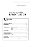
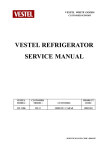
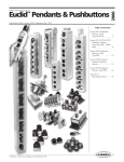
SERVICE MANUAL
UOC III AK49
Date
: 20/06/2005
Version
: V1.0
Unit
: Electronic Hardware Design
VESTEL R&D Service Manual
AK49-001
? Copyright 2003 VESTEL Group of Company
All rights reserved. Passing on and copying of this document, use and communication of its contents not permitted without written permission from VESTEL
TABLE OF CONTENTS
1.
1.1.
1.2.
1.3.
2.
INTRODUCTION
4
Purpose
Scope
General Features
4
4
4
GENERAL DESCRIPTION
5
2.1.
Introduction
5
2.2.
System Building Blocks
5
2.2.1.
UOC-III (Ultimate-One-Chip)
2.2.1.1.
2.2.1.2.
2.2.1.3.
2.2.1.4.
2.2.1.5.
2.2.1.6.
2.2.1.7.
2.2.1.8.
2.2.1.9.
2.2.1.10.
2.2.2.
8
8
8
9
9
9
10
11
12
14
15
Audio Power Amplifier
Headphone Amplifier
Pop Noise Protection Circuit
15
17
18
Deflection & Display Block
2.2.3.1.
2.2.3.2.
2.2.3.3.
2.2.3.4.
2.2.3.5.
2.2.3.6.
2.2.3.7
2.2.4.
Fav & B_Svhs & F_Svhs
Scart1
Scart2
Scart3
VestelBus
Audio
Port Allocations
Power Management
Input & Output Performance
Feature Board
Audio Block
2.2.2.1.
2.2.2.2.
2.2.2.3
2.2.3.
5
19
Horizontal Deflection
Vertical Deflection
CRT Board
Rotation
X-RAY Protection
Dynamic Focus
Screen & Focus Short Circuit Protection
SMPS BLOCK
2.2.4.1.
19
20
22
23
24
24
25
28
Primary Block
28
1
VESTEL R&D Service Manual
? Copyright 2003 VESTEL Group of Company
All rights reserved. Passing on and copying of this document, use and communication of its contents not permitted without written permission from VESTEL
AK49-001
2.2.4.2. Secondary Block
2.2.5 CABELING
29
31
2.2.6 CABLE SPECs
2.2.6.1 RGB CABLE
2.2.6.2 200V CABLE (with BSVM)
2.2.6.3 200V CABLE (with BSVM)
33
33
35
37
2.2.7 SAW FILTER
39
2.2.8 TUNER
40
3. AK49 CHASSIS MANUAL ADJUSTMENTS PROCEDURE
3.1 SMPS B+ADJUSTMENT
3.2 AFC ADJUSTMENT
3.3 FOCUS ADJUSTMENT
3.4 SCREEN ADJUSTMENT
41
41
41
41
42
4. AK49 CHASSIS PRODUCTION SERVICE MODE ADJUSTMENTS
43
5. MENU LANGUAGE TABLE
74
6.PICTURE MODES
75
7. CIRCUIT DIAGRAMS
79
8. APPENDIX
84
2
VESTEL R&D Service Manual
AK49-001
? Copyright 2003 VESTEL Group of Company
All rights reserved. Passing on and copying of this document, use and communication of its contents not permitted without written permission from VESTEL
Document History
Document
Versi
on
Date
Revision and
Review
Status
Prepared by
Approved by
History
v1.0
20.06.2005
MUHAMMED
M. KAGAN M. PANCAR
KAYA
SERDAR GÜLTEN
File Name: AK49_SM_V1.0
3
VESTEL R&D Service Manual
AK49-001
? Copyright 2003 VESTEL Group of Company
All rights reserved. Passing on and copying of this document, use and communication of its contents not permitted without written permission from VESTEL
1. Introduction
1.1.
Purpose
This document is prepared for the UOC3 TV project and describes the whole system features and
operating principles to be used in hardware design phase.
The document is based on “Device Specification UOCIII-Version 2.5” and “Introducing UOC-III” from
Philips Semiconductors.
1.2.
Scope
The document covers detailed descriptions of AK49 chassis system building blocks.
1.3.
General Features
AK49 is a 110? / 50 Hz. chassis which is capable of driving CRT sizes in the range of 24” – 33”,
including realflat and 16:9 CRT’s . The chassis has the following main features;
?
?
?
?
?
?
?
?
?
?
?
?
?
?
?
?
?
?
?
?
?
?
?
Remote Control
Colour Standards
; PAL, SECAM, NTSC,
Transmission standards ; B/G, L/L’ I/I’, DK,
Teletex
; 10 pages,
Intercarier/QSS sound proccessing,
Multi-standard alignment free PLL tuning,
PIP, PAP, POP, PAT, TAT ,
CTI option ,
2D Comb Filter ,2D/4H
Headphone with volume control,
SubWoofer option,
2 Full Scart with SVHS availability via Scart-2 , Scart-3 / BAV, FAV and F_SVHS /B_SVHS,
BSVM option,
Dynamic Focus option,
Rotation (Tilt) option,
NICAM/GERMAN Stereo,
Virtual Dolby option,
2 x 10W (%10 THD),
YPbPr input feature,
TV-DVD Combi ,
IDTV ,
TV-R/HDD,
EPG,
4
VESTEL R&D Service Manual
AK49-001
? Copyright 2003 VESTEL Group of Company
All rights reserved. Passing on and copying of this document, use and communication of its contents not permitted without written permission from VESTEL
2. General Description
2.1.
Introduction
This chapter describes system building blocks and their detailed discriptions.
2.2.
System Building Blocks
AK49 chassis main block are;
?
UOC3
: Microcontroller + Video Proccessor + Sound Proccessor + IF+Teletext
?
SMPS
: SMPS Controller, SMT, Bridge Rect., Line Filters
?
HV Block
: FBT, HOT, Vertical Amplifier, Line Driver, EW Amp.
?
AUDIO
: Audio Amp., DAC, Comperator.
?
CRT BOARD
: RGB Amp.
?
Feature Board
: PIP, CTI IC’s.
2.2.2 UOC-III (ULTIMATE-ONE-CHIP)
UOC3 is composed of microcontroller, video proccessor, sound proccessor and IF blocks. So, there
are digital and anolog parts in it named as Picasso and Cosmic respectively as shown below ;
UOC3 has standard and face down versions, pin squence differs between two version. After
investigation of the pining it is decided to use face down version for layout compability.
5
? Copyright 2003 VESTEL Group of Company
All rights reserved. Passing on and copying of this document, use and communication of its contents not permitted without written permission from VESTEL
VESTEL R&D Service Manual
AK49-001
Block diagram of the TV System with face-down version is;
6
? Copyright 2003 VESTEL Group of Company
All rights reserved. Passing on and copying of this document, use and communication of its contents not permitted without written permission from VESTEL
VESTEL R&D Service Manual
AK49-001
7
VESTEL R&D Service Manual
AK49-001
2.2.2.1 FAV & BAV & B_SVHS & F_SVHS
? Copyright 2003 VESTEL Group of Company
All rights reserved. Passing on and copying of this document, use and communication of its contents not permitted without written permission from VESTEL
B_SVHS and F_SVHS inputs can not be supported at the same time.
FAV & B_SVHS_Y & F_SVHS_Y inputs use same CVBS input. (cvbs2/74)
B_SVHS_ C & F_SVHS_C input is C2/C3(70).
FAV audio input is AUDIOin_5 L,R (94,95) and shared with F_SVHS.
BAV video input is CVBS1 (81) and can not be supported with SCART3 at the same time.
BAV audio input is AUDIOin_4 L,R (80,79) and shared with SCART3.
2.2.2.2 SCART1
SCART1 video input is (CVBS3/71) . SCART1 video input is also applied to Video Switch
IC(TEA6415C) for PIP application.
SCART1 video out will use (IFVO/86) front_end video output, that output is also used as SCART3
video output via a buffer circuit.
SCART1 RGB/fblk inputs are R(51), G(50), B(49), FBLK(52) .
SCART1 AUDIO input is AUDIOin_3 L,R ( 73,72) .
SCART1 AUDIO output is AUDIOout_SR,SL (93,92). Same output also used as SCART3 Audio output.
2.2.2.3 SCART2
SCART2 video input is CVBS4 (78) . SCART2 video input is also applied to Video Switch IC(TEA6415C)
for PIP application.
SCART2 supports SVHS input. SVHS / C input is C4 (77) , Y input is use same video input.
SCART2 video output is CVBSO/PIP (65). That video output is selectable, all inputs can be selected to
be output from SCART2.
SCART2 RGB inputs are R(59), G(57), B(58), FBLK/INSSW2 (54), except CTI/PIP option.
At PIP application ;
- There are PIP_CVBS, SCART1, SACRT2, SCART3, FAV video inputs and RGB, FBLK inputs to PIP IC.
-
If there is no CTI application, PIP output is applied to SCART2 RGB input directly.
-
In case of PIP&CTI combined application, PIP output will be input to CTI IC as YUV. The YUV
output of CTI IC will be applied to R/Vin(59), G/Yin(57), B/Uin(58) as YUV.
8
VESTEL R&D Service Manual
? Copyright 2003 VESTEL Group of Company
All rights reserved. Passing on and copying of this document, use and communication of its contents not permitted without written permission from VESTEL
AK49-001
YPbPr input is possible via SCART2 RGB lines with an adaptor.
In this case R/Vin(59), G/Yin(57), B/Uin(58) inputs can be used as;
- RGB,
- YUV,
- YPbPr inputs.
SCART2 audio inputs are AUDIOin_2 L,R ( 75) .
SCART2 audio outputs are AUDIOout_HPR,HPL (67,66). That output is also selectable .
2.2.2.4 SCART3
SCART3 video input is CVBS1 (81) . That input will also be used as optional BAV video input. and
applied to Video Switch IC(TEA6415C) for PIP application.
SCART3 video output will be SCART1 video output via a buffer circuit.
SCART3 audio inputs are AUDIOin_4 L,R (80,79). These audio inputs will also used for optional BAV
L,R and VESTELBUS L,R audio inputs.
SCART3 audio out will be through SCART1 audio outputs via a buffer circuit.
2.2.2.5 VESTELBUS(IDTV,DVD-Combi)
VESTELBUS video input is CVBS1 (81), so VESTELBUS will not be supported with SCART3 at the same
time.
VESTELBUS RGB inputs are SCART2 RGB inputs, so in case of VESTELBUS option SCART2 RGB
is not supported.
VESTELBUS UART input ;
- TXD
- RXD
- IRQ_DVB
TX
RX
INT2
(1),
(2),
(3).
VESTELBUS I2C input is standard I2C bus.
2.2.2.6 AUDIO
Main audio out is AUDIOout_LSR,LSL (69,68).
Selectable HP out is I2SD01 24) out to DAC.
Subwoofer out is I2SD02 (25) out to DAC.
9
VESTEL R&D Service Manual
AK49-001
? Copyright 2003 VESTEL Group of Company
All rights reserved. Passing on and copying of this document, use and communication of its contents not permitted without written permission from VESTEL
2.2.2.7 PORT ALLOCATIONS
(32)
(INT-0)
REMOTE
(31)
(INT-1)
TV_LINK
(30)
(Counter-Timer)
PROTECTION
(27)
(I2S Word Select)
I2S_WS
(26)
(I2S Clock)
I2S_CLK
(25)
(I2S OUT2)
I2S_Swoofer
(24)
(I2S OUT1)
I2S_HP
(23)
(I2S-IN/OUT)
WRITE-PROT.
(22)
(ON/OFF)
ON/OFF+LED
(21)
(SCL)
SCL
(20)
(SDA)
SDA
(18)
(PWM)
ROT/TILT
(17)
(PWM0)
PAP_LOW
(16)
(PWM1)
SW
(15)
(PWM2)
S_RESET
(14)
(ADC0)
AV1_STAT
(13)
(ADC1)
AV2_STAT
(10)
(ADC2)
AV3_STAT/DVD SENSE
(9)
(ADC3)
KEYB.+SERV.
(7)
(PWM3)
MUTE
(6)
(PWM4)
SAW_SW
(3)
(INT2)
IRQ/DVB
(2)
(UARTBUS)
RXD
(1)
(UART BUS)
TXD
10
VESTEL R&D Service Manual
AK49-001
? Copyright 2003 VESTEL Group of Company
All rights reserved. Passing on and copying of this document, use and communication of its contents not permitted without written permission from VESTEL
2.2.2.8 POWER MANAGEMENT
The power consumption of UOC3 is ;
Only 3,3V_Stb is necessary for the start-up. IC internally produces 2,5V and 1,8V at the Standby
mode. After start-up necessary 1,8V are produced by external regulators. So, we have 3,3V_Stb, 5V,
5V_Stb and 1,8V. for UOC3. We don’t have 8V. even for audio outputs (1,2V RMS achieved with 5V).
All the voltages are produced by SMPS except 1,8V.
RESET :
1V8 digital and 1V8 analogue are produced by using 2V5 DECDIG-signal. DECDIG-signal is given
11
VESTEL R&D Service Manual
? Copyright 2003 VESTEL Group of Company
All rights reserved. Passing on and copying of this document, use and communication of its contents not permitted without written permission from VESTEL
AK49-001
to base of Q108 Transistor and base of Q114 Transistor. The collector voltage becomes 1v8.
When the +3V3_stb voltage decreases below the 2V6 Q110 Transistor goes OFF condition so FETs
become ON. Q107 FET shorts 1V8 digital to ground and system is reset condition.
Another reset condition becomes when the S_Reset port is active. While S_Reset port is active, FETs
become ON. 1V8 digital is shorted to ground.
All the supply architecture of the UOC3 is as follows;
12
VESTEL R&D Service Manual
AK49-001
? Copyright 2003 VESTEL Group of Company
All rights reserved. Passing on and copying of this document, use and communication of its contents not permitted without written permission from VESTEL
2.2.2.9 INPUT & OUTPUT PERFORMANCE
EXTERNAL INPUT - OUTPUT PERFORMANCE
AUDIO OUTPUT IMPEDANCE
1 ? 0.15 Vp_p
Luminance 700 ± 15 % mVpp
Sync
300 ± 15 % mVpp
Burst
300 ± 15 % mVpp
DC level
2 V dc
75 ± 10 % O
1 ? 15 % Vp_p
500 ? 15 % Mvrms
500 ? 15 % mVrms
minimum 10 K?
maximum 1 KO
PIN 8 SWITCHING
Standard
PRIORITY BETWEEN SCARTS
Vestel Standard
CVBS INPUT VOLTAGE
CVBS OUTPUT VOLTAGE
VIDEO OUTPUT IMPEDANCE
RGB INPUT VOLTAGE
AUDIO INPUT VOLTAGE
AUDIO OUTPUT VOLTAGE
AUDIO INPUT IMPEDANCE
RECEPTION PERFORMANCE
NICAM STEREO SENSITIVITY LEVEL
50
90
32
30
35
40
40
BTSC STEREO SENSITIVITY LEVEL
NO BTSC
NOISE LIMITED SENSITIVITY LEVEL
TELETEXT EYEHEIGHT LEVEL
30 dB? V
% 45
CLOSED CAPTION SENSITIVITY LEVEL
NO CLOSED CAPTION
AFC PULL IN RANGE
-500 KHz / +800 KHz
± 5 MHz
USABLE MINIMUM SIGNAL LEVEL
USABLE MAXIMUM SIGNAL LEVEL
COLOUR KILLER LEVEL
SOUND KILLER LEVEL
SYNCHRONISING SENSITIVITY LEVEL
FM GERMAN STEREO SENSITIVITY LEVEL
TUNER RECEIVING RANGE
13
dBµV
dBµV
dBµV
dBµV
dBµV
dBµV
dBµV
VESTEL R&D Service Manual
AK49-001
? Copyright 2003 VESTEL Group of Company
All rights reserved. Passing on and copying of this document, use and communication of its contents not permitted without written permission from VESTEL
2.2.2.10 FEATURE BOARD ( PIP & CTI )
PIP&PAP and CTI applications performed with that feature board. For PIP&PAP application Micronas
SDA9488/SDA9489 and for CTI application Toshiba TA1366FG is used.
There is a socket on the board for external YUV input which will be used for DVD or IDTV application
with PIP&PAP and CTI feature. There are switches on the board for adaptation of application
configurations.
Only CTI Application
YUV output from UOC3 comes to CTI IC TA1366FG and goes back to UOC3 .
CTI & IDTV or DVD
CTI & PIP Application
YUV output from UOC3 comes to CTI IC TA1366FG , then inputs to PIP IC SDA9488. Any desired
external CVBS signal is directed to PIP IC via video switch and used for PIP picture on CTI applied
video signal. That video signal goes back to UOC3 as YUV.
14
VESTEL R&D Service Manual
AK49-001
? Copyright 2003 VESTEL Group of Company
All rights reserved. Passing on and copying of this document, use and communication of its contents not permitted without written permission from VESTEL
2.2.3
2.2.3.1
AUDIO BLOCK
AUDIO AMPLIFIER
TDA8928J 2X10W class D amplifier is used for audio amplification. It is supplied by +14V and –14V to
give 2X10W output to 8ohm. loads by %10 THD.
15
VESTEL R&D Service Manual
AK49-001
? Copyright 2003 VESTEL Group of Company
All rights reserved. Passing on and copying of this document, use and communication of its contents not permitted without written permission from VESTEL
Audio inputs Main_L and Main_R is applied via voltage comparator LM393 to amplifier.
swicthing outputs are then filtered by 33UH and 470NF.
SOUND PERFORMANCE
SOUND CALL UP TIME
Max. 4 sec.
MAXIMUM AUDIO OTPUT POWER (RF INPUT)
10W
MAXIMUM AUDIO OTPUT POWER (EXTERNAL INPUT)
10W
THD AT MAXIMUM AUDIO OUTPUT POWER (RF INPUT)
%10
THD AT MAXIMUM AUDIO OUTPUT POWER (EXTERNAL INPUT)
%10
THD AT 50 mW AUDIO OUTPUT POWER (RF INPUT)
%3
(IC spec.)
THD AT 50 mW AUDIO OUTPUT POWER (EXTERNAL INPUT)
%3
(IC spec.)
SIGNAL TO NOISE RATIO (RF INPUT)
50 db.
SIGNAL TO NOISE RATIO (EXTERNAL INPUT)
40 dB
SIGNAL TO BUZZ RATIO
40 dB
CROSSTALK: TV TO AV - AV TO TV
60 dB
RESIDUAL SOUND (RF INPUT)
20 mW/rms
RESIDUAL SOUND (EXTERNAL INPUT)
20 mW/rms
FREQUENCY RESPONSE (RF INPUT)
100 Hz – 10 kHz
FREQUENCY RESPONSE (EXTERNAL INPUT)
100 Hz – 10 kHz
BASS FREQUENCY RESPONSE (RF INPUT)
10 ± 2 dB
BASS FREQUENCY RESPONSE (EXTERNAL INPUT)
10 ± 2 dB
TREBLE FREQUENCY RESPONSE (RF INPUT)
10 ± 2 dB
TREBLE FREQUENCY RESPONSE (EXTERNAL INPUT)
10 ± 2 dB
POP NOISE
5 Vpp
HORIZONTAL HUM NOISE
15 mVrms
VERTICAL HUM NOISE
15 mVrms
VIDEO NOISE ON THE AUDIO OUTPUT
50 mVpp
16
PWM
VESTEL R&D Service Manual
AK49-001
? Copyright 2003 VESTEL Group of Company
All rights reserved. Passing on and copying of this document, use and communication of its contents not permitted without written permission from VESTEL
2.2.3.2
HEADPHONE AMPLIFIER
Headphone output is achieved by I2S out. I2S output is converted to anolog signal by DAC
CS4334 and then applied to TDA1308T amplifier.
SubWoofer output is achieved by the same way, I2S ouptut is converted to analog signal by DAC
CS4334 and applied to external SubWoofer amplifier board.DAC CS4334 will work at a rate of 32Fs
MCLK/LRCK = 512, 256 or 128 and De-emphasis feature of CS4334 is disabled.
HEADPHONE PERFORMANCE
MAXIMUM AUDIO OUTPUT POWER (RF INPUT)
22,5 ± 2,5 mWrms
MAXIMUM AUDIO OUTPUT POWER (EXTERNAL INPUT)
22,5 ± 2,5 mWrms
THD AT MAXIMUM AUDIO OUTPUT POWER (RF INPUT)
%10
THD AT MAXIMUM AUDIO OUTPUT POWER (EXTERNAL INPUT)
%10
THD AT 0.5 mW AUDIO OUTPUT POWER (RF INPUT)
%1
THD AT 0.5 mW AUDIO OUTPUT POWER (EXTERNAL INPUT)
%1
SIGNAL TO NOISE RATIO (RF INPUT)
40 dB
SIGNAL TO NOISE RATIO (EXTERNAL INPUT)
40 dB
17
VESTEL R&D Service Manual
AK49-001
? Copyright 2003 VESTEL Group of Company
All rights reserved. Passing on and copying of this document, use and communication of its contents not permitted without written permission from VESTEL
2.2.2.3 POP NOISE PROTECTION CIRCUIT
This circuit is used to prevent pop noise in AC turn-off. While TV is working due to +14V. T1
is OFF . In turn-0ff situation BE voltage of T1 becomes negative and transistor goes to ON
condition ,so it drives T2 and T2 pull-down mute pin to perform muting.
18
VESTEL R&D Service Manual
AK49-001
? Copyright 2003 VESTEL Group of Company
All rights reserved. Passing on and copying of this document, use and communication of its contents not permitted without written permission from VESTEL
2.2.3
DEFLECTION & DISPLAY BLOCK
2.2.3.1 Horizontal Deflection
Deflection block consist of following main parts,
Horizontal driver transistor (Q601),
Horizontal driver (TR600),
HOT (Horizontal Output Transistor) (Q600),
FBT (TR601),
E/W transistor (Q602),
E/W coil (L601),
E/W injection Coil (Bridge Coil) (L602),
Linearity Coil (L603),
Flyback Capacitors (C608, C607),
S-correction capacitor (C615 ve C613),
Modulated S-correction capacitor (C611),
Hdrive signal is buffered and applied to line driver transistor by a capacitor.
Line driver produces necessary base currents, parallel diode to base series resistor speeds up the
reverse base current.
UOC3 has soft-start and soft-stop features to have more safe operation. There are two base current
adjustment resistors on the circuit. Collector current differs according to CRT sizes .
Tube dependent components are choosen to fit best picture performance by keeping;
11,5 usec. Flyback time,
Max. 1300V. collector voltage (peak-detect mode measurement)
Max. 500V. at the diode modulator cathode (D605).
Max. 20V. (peak-detect mode measurement) at the E/W transistor drain.
Max. 200V video B+ voltage.
19
VESTEL R&D Service Manual
AK49-001
? Copyright 2003 VESTEL Group of Company
All rights reserved. Passing on and copying of this document, use and communication of its contents not permitted without written permission from VESTEL
2.2.3.2 Vertical Deflection
TDA8359J (IC502) vertical amplifier is used for vertical deflection. It’s 3,2A. current capability makes
it enable to drive all 50Hz. CRT screen sizes.
Differential vertical drive signals; resistor network at inputs are chosen CF type to
minimize temperature sensitivity of TV set. Those resistors can be changed to MF type in
case of heat run failure.
Power resistor R633, R634 values will change according to CRT sizes.
20
? Copyright 2003 VESTEL Group of Company
All rights reserved. Passing on and copying of this document, use and communication of its contents not permitted without written permission from VESTEL
VESTEL R&D Service Manual
AK49-001
21
VESTEL R&D Service Manual
AK49-001
? Copyright 2003 VESTEL Group of Company
All rights reserved. Passing on and copying of this document, use and communication of its contents not permitted without written permission from VESTEL
2.2.3.3 CRT Board
TDA6108AJF is used as RGB amplifier. Main feature of that triple amplifier is the increased fixed gain
of 81. It’s 8 MHz. Bandwidth at 100Vpp video signal makes it enable to use in all 50Hz. TV
applications.
22
VESTEL R&D Service Manual
? Copyright 2003 VESTEL Group of Company
All rights reserved. Passing on and copying of this document, use and communication of its contents not permitted without written permission from VESTEL
AK49-001
CRT board have single and double focus CRT socket options.
There are CC type 1,5K series flash current limiting resistors (R903, R904, R905) on the RGB lines. In
addition to resistors BAV21 clamp diodes (IC901,IC902,IC903) are introduced.
Spot Killer circuit pulls G1 to –200V by Q700 at turn off instant.
BSVM amplifier circuit modulates the beam to have sharper images at the adges of CRT. Basicly, it
amplifies the software delayed controlled BSVM signal and apply it to BSVM winding of neck.
2.2.3.4 ROTATION
PWM rotation output of UOC3 is first converted to DC then applied to rotation circuit. OPAMP LM358N
(IC600) and medium power transistors (Q601, Q602) performs DC amplification necessary for rotation
coil.
23
VESTEL R&D Service Manual
AK49-001
? Copyright 2003 VESTEL Group of Company
All rights reserved. Passing on and copying of this document, use and communication of its contents not permitted without written permission from VESTEL
2.2.3.5 X-RAY PROTECTION
This circuit is used to protect the system X-ray caused by HV. While Anode voltage is bellow 33kv, T1
is off due to 80 volt because BE voltage of T1 becomes negative. While Anode voltage is above 33 kv.
80 voltage increases, it becomes approximately 90 volt. At that condition T1 is ON due to 90 volt
because BE voltage of T1 becomes positive, so it drives protection.
2.2.3.6 DYNAMIC FOCUS
E/W injection signal is converted to sinus shape after it passes LC circuit. Then the signal is amplified
via coil and applied to Dynamic focus.
24
VESTEL R&D Service Manual
AK49-001
? Copyright 2003 VESTEL Group of Company
All rights reserved. Passing on and copying of this document, use and communication of its contents not permitted without written permission from VESTEL
2.2.3.7 SCREEN & FOCUS SHORT CIRCUIT PROTECTION
Above circuit is used for protection against screen & focus grounding. Basicly the base
of PNP transistor Q609 is connected to screen&focus potentiometer of FBT, in another words
FBT focus pack is connected to ground via R654. The voltage at the base of that transistor is
normally higher then the zener voltage at the emitter. When any short circuit occurs at focus
or screen the base voltage is decreased to a value lower then zener voltage, that forces
transistor to conduction and trigers another circuit which will force UC to protection mode. In
protection mode LED becomes RED and remote control does not work.
25
VESTEL R&D Service Manual
AK49-001
? Copyright 2003 VESTEL Group of Company
All rights reserved. Passing on and copying of this document, use and communication of its contents not permitted without written permission from VESTEL
GEOMETRY PERFORMANCE
ASPECT RATIO
NON-LINEARITY (Horizontal & Vertical)
% 10
DE-CENTERING (Horizontal & Vertical)
%1
OVER-SCANNING (Top, Bottom, Left, Right)
% 2,5
UNDER-SCANNING (Top, Bottom, Left, Right)
% 97,5
RASTER ROTATION / TILT
3 mm.
PARALELLOGRAM (Left counter, Right Counter)
% 1,5
TARPEZIUM (Horizontal, Vertical)
% 1,5
OUTLINE DISTORTION (Top, Bottom, Right, Left outline distortion)
% 1,5
INNER DISTORTION (Top, Bottom, Right, Left inner distortion)
% 1,5
BENDING (Top right, top left, bottom left, bottom right corner bending)
% 10
EHT AND DEFLECTION PERFORMANCE
ANODE VOLTAGE
CRT spec.
BEAM CURRENT
CRT spec.
HEATER VOLTAGE
CRT spec.
EHT REGULATION
% 1,5
HORIZONTAL FLYBACK VOLTAGE
HOT spec.
HORIZONTAL FLYBACK TIME
12 usec. Max
VERTICAL FLYBACK VOLTAGE
Vertical IC spec.
VERTICAL FLYBACK TIME
1 msec. Max
SCREEN VOLTAGE
CRT spec.
FOCUS VOLTAGE
CRT spec.
FOCUSING
PICTURE PERFORMANCE
IMAGE CALL UP TIME
9 sec. Max
WHITE BALANCE
x=285 ± 3 , y=293 ± 3
MAXIMUM LUMINANCE
120 ± 10 Cd/m²
VIDEO BANDWIDTH
3,5 Mhz. Min
SIGNAL TO NOISE RATIO
40 dB min
2T PULSE WIDTH
200 ± 40 nsec
OVER-SHOOT
% 10 max
UNDER-SHOOT
% 10 min
CONTRAST RATIO
60 min
CONTRAST LEVEL
90 – 100V min
CROSSTALK: TV TO AV - AV TO TV
Should be not visible
TOLERANCE TO VISION OVER MODULATION
No effect up to %30 modulation
COLOUR PURITY
Not visible from 1,8m distance
COLOR SCYNCHRONISATION
0,5 sec delay max.
PICTURE SWAY
No picture shake allowed
MOIRE
No moire effect allowed
26
VESTEL R&D Service Manual
? Copyright 2003 VESTEL Group of Company
All rights reserved. Passing on and copying of this document, use and communication of its contents not permitted without written permission from VESTEL
AK49-001
RINGING
No visible effect allowed
SMEARING
INTERLACE AND JITTER
% 10
No flicker effect caused by brightnes
control allowed
No jitter is allowed
HANOVER BLIND
No hanover blind is allowed
HUM ON VISION
No hum bars allowed in picture
FLYBACK LINES
No visible flyback line allowed
FLICKER
FOLDOVER
No foldover in the picture allowed
CURTAIN EFFECT
No oscillation in picture allowed
MANHEIM EFFECT
% 1,5 max
MISCONVERGENCE
1,8 max.
27
VESTEL R&D Service Manual
AK49-001
? Copyright 2003 VESTEL Group of Company
All rights reserved. Passing on and copying of this document, use and communication of its contents not permitted without written permission from VESTEL
2.2.4
2.2.4.1
SMPS BLOCK
PRIMARY BLOCK
AC power applied via AC inlet, line filter components prevent chassis from incoming noise of AC line,
also prevents AC line against created noises by TV. Bridge rectifier and bulk capacitor converts AC
voltage to DC voltage. Applied DC voltage to primary winding is then swicthed via MOSFET by primary
controller in a controlled manner.
SMPS controller works on quasi-resonant PWM and gets first supply voltage from AC line (SMPS
Controller supply). Controller drives MOSFET according to feedback information supplied by
shunt regulator and opto-coupler, according to that information adjusts on-time of MOSFET for
required power. After the start-up in normal operation mode SMPS controller is supplied by SMT.
Primary block consist of following main parts,
AC Inlet (PL800),
Fuse (F800),
Varistor (R800 and R802),
Line Filter For EMC (C801,L800,C802),
SMPS Controller (IC804),
SMPS Controller supply for first Start-up and at Stand-by (D823, C800, D801, R801),
Bridge Rectifier (D800),
Rectifier For SMPS Controller(D802),
PFC Coil Socket (PL801),
PFC Coil Dumping Cap (C807),
Bulk Cap (C810),
Clamping Circuitry (R810, C814, C815, D816),
SMT (Switch Mode Transformer) (TR800),
SMT Driver MOSFET (Q802),
Current Sense Resistors (R814, 815,R816, R819),
Protection Components for MOSFET Failure (D805, D806, R813),
28
VESTEL R&D Service Manual
AK49-001
? Copyright 2003 VESTEL Group of Company
All rights reserved. Passing on and copying of this document, use and communication of its contents not permitted without written permission from VESTEL
2.2.4.2 SECONDARY BLOCK
Switching primary winding of SMT induces voltages to secondary windings of SMT. Induced
voltages are then rectified by secondary recitification diodes and capacitors.
Secondary block consist of following main parts,
Optocoupler for feedback (IC805),
Shunt Requlator for Requlation at Normal Mode (IC806),
B+ Sense Resistors for Apply Shunt Requlator (R833, R834, VR800, R831),
Rectifier and DC line Components for B+ (D817, C827, C828, C826, L805, D811, R867),
B+ Over Current Sense Components (R837,C840,R850, R838, Q806, R851, R853, C850,D813),
Audio + and - Supply Rectifiers and DC line Components (D818,C829, C831, R839, C841, D820, C830,
C832, R840, C842)
+ 14 Supply Rectifiers and DC line Components (D819, C833,C843),
+ 8V Supply Rectifiers and DC line Components (D808, C834, C844),
+ 8V Controller Supply Rectifiers and DC line Components at Normal Mode(D809,C836),
+ 8V Controller Supply Rectifiers and DC line Components at Stand by Mode (IC802, L804, R847,
D822),
IC 415 (Tristor) Trigering components (R848, C849),
IC 415 (Tristor) Trigering Control Components (C848, R849, Q810, R846),
Short Circuit Sense For +5V (R862, R863, Q813, R861, D815 ),
Power Fail or Short Circuit Inform Circuit to Controller (R859, R860, C851, Q812),
SMT secondary voltages / currents;
29
VESTEL R&D Service Manual
SMT
? Copyright 2003 VESTEL Group of Company
All rights reserved. Passing on and copying of this document, use and communication of its contents not permitted without written permission from VESTEL
AK49-001
20
150V / 800mA
21
GND
18
+13,5V / 1,5A
19
GND
17
- 13,5V / 1,5A
15
+ 14V / 1A
14
8V / 1A
16
GND
13
22V / 800mA
Stand-by and Normal-mode controlled by microcontroller. On/Off port is high when TV is in stand-by
and low at normal-mode.
POWER SUPPLY PERFORMANCE
USABLE MINIMUM AND MAXIMUM OPERTAING VOLTAGES
170 V. min , 270 V. max
(170 V- 270V)
DROP OUT VOLTAGE
155 V.
START UP VOLTAGE
SMPS OUTPUT VOLTAGES
170 V.
< 1W in Stand-by,
max.
± 0,5 V. of design value
SMPS FET DRAIN VOLTAGE
% 90 of MOSFET spec.
SMPS FET GATE VOLTAGE
% 90 of MOSFET spec.
SMPS FET OPERATING FREQUENCY
Fix
POWER CONSUMPTION
30
160W
? Copyright 2003 VESTEL Group of Company
All rights reserved. Passing on and copying of this document, use and communication of its contents not permitted without written permission from VESTEL
VESTEL R&D Service Manual
AK49-001
RGB cables are shown below. First is the RGB signal cable. Second is the RGB power cable.
2.2.5
CABELING
Pin NO
1
2
3
4
5
6
7
Signal
Blue
Green
Red
GND
BLKIN
GND
BSVM
31
? Copyright 2003 VESTEL Group of Company
All rights reserved. Passing on and copying of this document, use and communication of its contents not permitted without written permission from VESTEL
VESTEL R&D Service Manual
AK49-001
Pin NO Signal
1
+14 volt
2
+80 volt
3
EHTINFO
4
HEATER
5
GND
6
7
200 volt
32
? Copyright 2003 VESTEL Group of Company
All rights reserved. Passing on and copying of this document, use and communication of its contents not permitted without written permission from VESTEL
VESTEL R&D Service Manual
AK49-001
2.2.6 CABLE SPECs
2.2.6.1 RGB CABLE
33
? Copyright 2003 VESTEL Group of Company
All rights reserved. Passing on and copying of this document, use and communication of its contents not permitted without written permission from VESTEL
VESTEL R&D Service Manual
AK49-001
34
? Copyright 2003 VESTEL Group of Company
All rights reserved. Passing on and copying of this document, use and communication of its contents not permitted without written permission from VESTEL
VESTEL R&D Service Manual
AK49-001
2.2.6.2 200V CABLE (with BSVM)
35
? Copyright 2003 VESTEL Group of Company
All rights reserved. Passing on and copying of this document, use and communication of its contents not permitted without written permission from VESTEL
VESTEL R&D Service Manual
AK49-001
36
? Copyright 2003 VESTEL Group of Company
All rights reserved. Passing on and copying of this document, use and communication of its contents not permitted without written permission from VESTEL
VESTEL R&D Service Manual
AK49-001
2.2.6.3 200V CABLE(without BSWM)
37
? Copyright 2003 VESTEL Group of Company
All rights reserved. Passing on and copying of this document, use and communication of its contents not permitted without written permission from VESTEL
VESTEL R&D Service Manual
AK49-001
38
VESTEL R&D Service Manual
AK49-001
? Copyright 2003 VESTEL Group of Company
All rights reserved. Passing on and copying of this document, use and communication of its contents not permitted without written permission from VESTEL
2.2.7. SAW FILTER
K3953M:
Standard
B/G, D/K, I, L/L’
Features
TV IF video filter with Nyquist slopes at 33,90 MHz and 38,90 MHz
Constant group delay
Suitable for CENELEC EN 55020
Terminals
Tinned CuFe alloy
Pin configuration
1 Input
2 Input - ground
3 Chip carrier - ground
4 Output
5 Output
K3958M:
Standard
B/G, D/K, I, L/L’
Features
TV IF video filter with Nyquist slopes at 33.90 MHz and 38.90 MHz
Constant group delay
Terminal and Pin configuration are the same with K3953M
K9356M:
Standard
B/G, D/K, I, L
Features
TV IF audio filter with pass band for sound carriers at 32,40 MHz (D/K, L), 32,90 MHz (I) and 33,40
MHz (B/G)
Terminal and Pin configuration are the same with K3953M
K9656M:
Standard
B/G, D/K, I, L/L’
Features
TV IF audio filter with two channels
Channel 1 (L’) with one pass band for sound carriers at 40,40 MHz (L’) and 39,75 MHz (L’- NICAM)
Channel 2 (B/G, D/K, L, I) with one pass band for sound carriers between 32,35 MHz and 33,40 MHz
Terminal and Pin configuration are the same with K3953M
39
VESTEL R&D Service Manual
AK49-001
? Copyright 2003 VESTEL Group of Company
All rights reserved. Passing on and copying of this document, use and communication of its contents not permitted without written permission from VESTEL
2.2.8. TUNER
The hardware and software of the TV is suitable for tuners, supplied by different companies, which
are selected from the Service Menu. These tuners can be combined VHF, UHF tuners suitable for
CCIR systems B/G, H, L, L´, I/I´, and D/K. The tuning is available through the digitally controlled I2C
bus (PLL). Below you will find info on one of the Tuners in use.
General description of UV1316:
The UV1316 tuner belongs to the UV 1300 family of tuners, which are designed to meet a wide range
of applications. It is a combined VHF, UHF tuner suitable for CCIR systems B/G, H, L, L’, I and I’. The
low IF output impedance has been designed for direct drive of a wide variety of SAW filters with
sufficient suppression of triple transient.
Features of UV1316:
1. Member of the UV1300 family small sized UHF/VHF tuners
2. Systems CCIR: B/G, H, L, L’, I and I’; OIRT: D/K
3. Digitally controlled (PLL) tuning via I2C-bus
4. Off-air channels, S-cable channels and Hyperband
5. World standardized mechanical dimensions and world standard pinning
6. Compact size
7. Complies to “CENELEC EN55020” and “EN55013”
Pinning:
1.
Gain control voltage (AGC)
2.
Tuning voltage
3.
I²C-bus address select
4.
I²C-bus serial clock
5.
I²C-bus serial data
6.
Not connected
7.
PLL supply voltage
8.
ADC input
9.
Tuner supply voltage
10.
Symmetrical IF output 1
11.
Symmetrical IF output 2
:
:
4.0V, Max: 4.5V
:
:
:
Max: 5.5V
Min:-0.3V, Max: 5.5V
Min:-0.3V, Max: 5.5V
:
5.0V, Min: 4.75V, Max: 5.5V
33V, Min: 30V, Max: 35V
40
VESTEL R&D Service Manual
AK49-001
? Copyright 2003 VESTEL Group of Company
All rights reserved. Passing on and copying of this document, use and communication of its contents not permitted without written permission from VESTEL
3
AK49 CHASSIS MANUAL ADJUSTMENTS PROCEDURE
Before starting with the alignment procedure, make sure that all the potentiometers on the
chassis and also screen and focus pots are in the medium position.
3.1. SMPS B+ ADJUSTMENT
Prior to first run of TV chasis , FBT screen and focus potentiometers should be set to middle
positions then B+ voltage is measured. If this value is different from the list below ;VR800 is adjusted
to specified value below.
SYSTEM VOLTAGE
145 V±0.5V
145 V±0.5V
TYPE OF CRT
32” 16:9 RF Panasonic W76EKW10X21
28” 16:9 RF Thompson THO021X131
3.2.AFC ADJUSTMENTS
AFC is automatically adjusted from software, when f (IF) is selected 38.9MHz for negative
modulation and 33.9MHz for positive modulation from the service menu.
3.3.
FOCUS ADJUSTMENTS
TV is tuned to the signal. Then focus potantiometer (the upper pot on the rear side of
the FBT transformer) is adjusted for optimum focusing drive. For double focus tubes,there
are two focus potentiometer; each of them should be adjusted for optimum focus on the
screen
41
VESTEL R&D Service Manual
AK49-001
? Copyright 2003 VESTEL Group of Company
All rights reserved. Passing on and copying of this document, use and communication of its contents not permitted without written permission from VESTEL
3.4 SCREEN ADJUSTMENTS
For screen adjustment VG2 item should be selected at the service menu.
then the screen potentiometer is gently adjusted until the “STABLE IN” sign appears.
42
VESTEL R&D Service Manual
AK49-001
? Copyright 2003 VESTEL Group of Company
All rights reserved. Passing on and copying of this document, use and communication of its contents not permitted without written permission from VESTEL
4 15.AK49 CHASSIS PRODUCTION SERVICE MODE ADJUSTMENTS
All system, geometry and white balance alignments are performed in production service mode.
Before starting the production mode alignments, make sure that all manual adjustments are done
correctly. To start production mode alignments enter the MAIN MENU and then press the digits 4, 7, 2
and 5
To store the settings press “OK” button.
Entire service menu parameters of AK49 CHASSIS are listed below.
FAPS
The option of APS (Automatic Program Searching) item are ON and OFF. In order to active APS
installation procedure when TV is turned for the very first time, select ON. Inorder to start TV without
APS installation procedure, select OFF.
S-No
001
OSD
FAPS
Description
First APS, activates factory settings and when
TV is opened first APS menu comes.
MinMax
Def.
OSD
ISPM
Description
In System Programming Mode, for software
update.
MinMax
Def.
On/Off
Off
ISPM
S-No
002
43
VESTEL R&D Service Manual
AK49-001
? Copyright 2003 VESTEL Group of Company
All rights reserved. Passing on and copying of this document, use and communication of its contents not permitted without written permission from VESTEL
INIT
S-No
003
OSD
INIT
Description
Initialise NVM
MinMax
On/Off
Def.
Off
AGCSPD
S-No
005
OSD
AGCSPD
Description
IF AGC speed
MinMax
0..3
Def.
1
MinMax
0..63
Def.
33
AGCTO
S-No
006
OSD
AGCTO
Description
AGC Take over. Also used as TOP when an
internal AGC tuner is used.
COFF
S-No
007
OSD
COFF
Description
Cut off
MinMax
Def.
OSD
VSD
Description
MinMax
0..63
Def.
31
OSD
VG2
Description
MinMax
0..63
Def.
31
VSD
S-No
008
Vertical scan disable
VG2
S-No
009
Adjustment Vg2 voltage.
TUBE
S-No
010
OSD
TUBE
Description
4:3 picture tube used or 16:9
picture tube used
MinMax
0 = 16:9
1 = 4:3
Def.
Depends
on
the
chassis
selected.
VERT ZOOM
S-No
011
OSD
VERT ZOOM
Description
MinMax
0..63
Vertical zoom for 16:9
44
Def.
35
VESTEL R&D Service Manual
AK49-001
? Copyright 2003 VESTEL Group of Company
All rights reserved. Passing on and copying of this document, use and communication of its contents not permitted without written permission from VESTEL
VERT SLOP
S-No
012
OSD
VERT SLOP
Description
MinMax
0..63
Vertical slope
Def.
37
VERT SHIFT
Change Vertical Shift by pressing “? /? ” buttons till the test pattern is vertically centered. Horizontal
line at the center of the test pattern is in equal distance both to upper and lower side of the picture
tube. Check and readjust V-SHIFT item if the adjustment becomes improper after some other
geometric adjustments are done.
S-No
013
OSD
VERT SHIFT
Tanim
Vertical shift for Wide Screen 4:3, 16:9
MinMax
0..63
Def.
25
VERT AMP
Change Vertical Amplitude by pressing “? /? ” buttons till horizontal black lines on both the upper and
lower part of the test pattern become very close to the upper and lower horizontal sides of picture
tube and nearly about to disappear. Check and readjust V-SIZE item if the adjustment becomes
improper after some other geometric adjustments are done.
S-No
014
OSD
VERT AMP
Description
Vertical amplitude (VA)
MinMax
0..63
Def.
33
SCORRECTION
Change S-Correction by pressing “? /? ” buttons till the size of squares on both the upper and lower
part of test pattern become equal to the squares laying on the vertical center of the test pattern.
Check and readjust S-COR item if the adjustment becomes improper after some other geometric
adjustments are done.
S-No
015
OSD
SCORRECTION
Description
S-Correction
MinMax
0..63
Def.
11
OSD
V-LINC
Description
VLx, 0: Tam, 1: Sadece alt, 2: Sadece üst
MinMax
0..2
Def.
0
V-LINC
S-No
016
V-LINEARTY
45
VESTEL R&D Service Manual
? Copyright 2003 VESTEL Group of Company
All rights reserved. Passing on and copying of this document, use and communication of its contents not permitted without written permission from VESTEL
AK49-001
Change Vertical linearity by pressing “? /? ” buttons till all the size of squares of the test pattern
become in equal size from the top of the screen to its bottom of the whole screen. Check and
readjust LINRT item if the adjustment becomes improper after some other geometric adjustments are
done. (especially after than S-COR adjustment)
S-No
017
OSD
V-LINEARTY
Description
Vertical linearity
MinMax
0..63
Def.
32
EW WIDTH
Change EW width by pressing “? /? ” buttons till no under-scan condition will happen, i.e. no white
bars on the left and right side of the test pattern will be visible nor picture will be so wide. Check and
readjust H-SIZE item if the adjustment becomes improper after some other geometric adjustments
are done.
S-No
018
OSD
EW WIDTH
Description
East West width for 16:9
MinMax
0..63
Def.
48
East West width for 4:3
0..63
18
HOR SHIFT
Change Horizontal Shift by pressing “? /? ” buttons till the the test pattern is horizontally in equal
distance both to right and left sides of the picture tube. Check and readjust H-SHIFT item if the
adjustment becomes improper after some other geometric adjustments are done.
S-No
019
OSD
HOR SHIFT
Description
Horizontal shift
MinMax
0..63
Def.
31
EW PARAB
Change EW Parabol by pressing “? /? ” buttons till vertical lines close to the both sides of the picture
frame become parallel to vertical sides of picture tube without any bending to left or to right side of
the screen. Check and readjust PARAB item if the adjustment becomes improper after some other
geometric adjustments are done.
S-No
020
OSD
EW PARAB
Description
East West Parabola width 16:9
MinMax
0..63
Def.
25
East West Parabola width 4:3
0..63
35
TRAPEZ
Change Trapezium by pressing “? /? ” buttons till vertical lines, especially lines at the sides of the
picture frame became parallel to the both sides of picture tube as close as possible. Check and
46
VESTEL R&D Service Manual
AK49-001
? Copyright 2003 VESTEL Group of Company
All rights reserved. Passing on and copying of this document, use and communication of its contents not permitted without written permission from VESTEL
readjust TRPEZ item if the adjustment becomes improper after some other geometric adjustments are
done.
S-No
021
OSD
TRAPEZ
Description
East West Trapezium for 16:9
MinMax
0..63
Def.
26
East West Trapezium for 4:3
0..63
30
UC PARAB
Change Upper Correction by pressing “? /? ” buttons till vertical lines at the upper corners of
the picture frame become vertical and parallel to vertical corner sides of picture tube. Check
and readjust U.COR item if the adjustment becomes improper after some other geometric
adjustments are done.
S-No
022
OSD
UC PARAB
Description
Upper Corner Parabola for 16:9
MinMax
0..63
Def.
1
Upper Corner Parabola for 4:3
0..63
13
LC PARAB
Change Lower Correction by pressing “? /? ” buttons till vertical lines at the lower corners of the
picture frame become vertical and parallel to vertical corner sides of picture tube. Check and readjust
L.COR item if the adjustment becomes improper after some other geometric adjustments are done.
S-No
023
OSD
LC PARAB
Description
Lower Corner Parabola for 16:9
MinMax
0..63
Def.
5
Lower Corner Parabola for 4:3
0..63
16
HOR BOW
Change Horizantal Bow by pressing “? /? ” buttons till the vertical lines especially ones close to the
left and right sides will of equal and symmetrical bending, i.e. they together will neither be towards
left side nor right side. Check and readjust BOW item if the adjustment becomes improper after some
other geometric adjustments are done.
S-No
024
OSD
HOR BOW
Description
Horizontal Bow for 16:9
MinMax
0..63
Def.
28
Horizontal Bow for 4:3
0..63
42
47
VESTEL R&D Service Manual
AK49-001
? Copyright 2003 VESTEL Group of Company
All rights reserved. Passing on and copying of this document, use and communication of its contents not permitted without written permission from VESTEL
PARALLEL
S-No
025
OSD
PARALLEL
Description
East West Parabola Width 16:9
MinMax
0..63
Def.
34
East West Parabola Width 4:3
0..63
33
WBF
A wide blanking pulse can be activated in the RGB outputs by means of the HBL bit in
subaddress 43H. The start of this blanking can be adjusted by means of the WBF
S-No
026
OSD
WBF
Description
start of wide blanking
MinMax
0..15
Def.
10
WBR
A wide blanking pulse can be activated in the RGB outputs by means of the HBL bit in
subaddress 43H. The end of this blanking can be adjusted by means of the WBF
S-No
027
OSD
WBR
Description
end of wide blanking
MinMax
0..15
Def.
8
Description
MinMax
Def.
Description
MinMax
Def.
WBF14
S-No
028
OSD
WBF14
WBR14
S-No
029
OSD
WBR14
60HZ EWW
S-No
030
OSD
60HZ EWW
Description
60Hz EW Width offset
MinMax
0..63
48
Def.
31
VESTEL R&D Service Manual
AK49-001
? Copyright 2003 VESTEL Group of Company
All rights reserved. Passing on and copying of this document, use and communication of its contents not permitted without written permission from VESTEL
60HZ HSH
S-No
031
OSD
60HZ HSH
Description
60Hz Horizontal Shift offset
MinMax
0..63
Def.
31
Description
60Hz Vertical Shift offset
MinMax
0..63
Def.
31
Description
60Hz Vertical Zoom offset
MinMax
0..63
Def.
31
60HZ VSH
S-No
032
OSD
60HZ VSH
60HZ VZ
S-No
033
OSD
60HZ VZ
ROT
This adjustment only works when the TV has rotation option. Change TILT by pressing “? /? ”
buttons to rotate the complete raster clock-wise and counter clock-wise depending on the CRT. Check
and readjust TRPEZ item if the adjustment becomes improper after some other geometric
adjustments are done.
S-No
034
OSD
ROT
Description
Rotation
MinMax
0..63
Def.
49
ROT-M
S-No
035
OSD
ROT-M
Description
Enable Rotation item in the menu.
MinMax
0..1
Def.
1
OIF
This control is intended to correct for DC offset in the IF-PLL to improve the S/N ratio of the intercarrier sound
signal.
S-No
036
OSD
OIF
Description
Correct DC offset in the IF-PLL
MinMax
0..63
Def.
32
IF
The IF-PLL demodulator uses an internal VCO (no external LC-circuit required) which is calibrated by
means of a digital control circuit which uses the clock frequency of the m-Controller as a reference.
The required IF frequency for the various standards can be set
49
VESTEL R&D Service Manual
AK49-001
? Copyright 2003 VESTEL Group of Company
All rights reserved. Passing on and copying of this document, use and communication of its contents not permitted without written permission from VESTEL
S-No
037
OSD
IF
Description
PLL demodulator frequency
MinMax
58P75; 45P75;
38P9 ; 38P0 ;
33P4 ;
33P9/43P008
OSD
OFR
Description
Option Enable Frequency in Install Menu
Def.
38P9
OFR
S-No
038
MinMax
0..1
Def.
1
FFI
Fast filter IF-PLL; increased time constant & normal time constant
S-No
039
OSD
FFI
Description
Fast filter IF-PLL
MinMax
0, 1
Def.
0
S-No
OSD
Description
MinMax
Def.
040
BS1
Tuner Band VHF1
0..15
1
OSD
BS2
Description
Tuner Band VHF3
MinMax
0..15
Def.
2
OSD
BS3
Description
Tuner Band UHF
MinMax
0..15
Def.
4
BS1
BS2
S-No
041
BS3
S-No
042
CB
S-No
043
OSD
CB
Description
Tuner Control Byte
MinMax
0..255
Def.
142
OSD
B1-H
Description
Tuner VHF1 Boundary High Byte
MinMax
0..255
Def.
12
B1-H
S-No
044
50
VESTEL R&D Service Manual
AK49-001
? Copyright 2003 VESTEL Group of Company
All rights reserved. Passing on and copying of this document, use and communication of its contents not permitted without written permission from VESTEL
B1-L
S-No
045
OSD
B1-L
Description
Tuner VHF1 Boundary Low Byte
MinMax
0..255
Def.
32
OSD
B2-H
Description
Tuner VHF3 Boundary High Byte
MinMax
0..255
Def.
30
OSD
B2-L
Description
Tuner VHF3 Boundary Low Byte
MinMax
0..255
Def.
2
OSD
FRAV
Description
Peaking center frequency for AV
MinMax
0..3
Def.
0
B2-H
S-No
046
B2-L
S-No
047
FRAV
S-No
048
YSCM
S-No
049
OSD
YSCM
Description
Y-delay adjustment for SECAM
MinMax
0..15
Def.
12
OSD
YNTS
Description
Y-delay adjustment for NTSC
MinMax
0..15
Def.
2
OSD
YPAL
Description
Y-delay adjustment for PAL
MinMax
0..15
Def.
2
OSD
YAV1
Description
Y-delay adjustment for AV-1
YNTS
S-No
050
YPAL
S-No
051
YAV1
S-No
052
51
MinMax
0..15
Def.
4
VESTEL R&D Service Manual
AK49-001
? Copyright 2003 VESTEL Group of Company
All rights reserved. Passing on and copying of this document, use and communication of its contents not permitted without written permission from VESTEL
YAV2
S-No
053
OSD
YAV2
Description
Y-delay adjustment for AV-2
MinMax
0..15
Def.
4
OSD
Y_S1
Description
Y-delay adjustment for S-VHS-1
MinMax
0..15
Def.
4
OSD
Y_S2
Description
Y-delay adjustment for S-VHS-2
MinMax
0..15
Def.
4
OSD
COMB
Description
Y_S1
S-No
054
Y_S2
S-No
055
COMB
S-No
056
MinMax
comb filter active
Def.
1
Comb filter mode
comb filter not active 0
Depends on
the chassis
selected.
BLCS
S-No
058
OSD
BLCS
Description
Adjusts Black stretch functions
MinMax
0 = Disable
1 = Enable
Def.
0
OSD
BLUS
Description
Adjusts Black stretch functions
MinMax
0 = Disable
1 = Enable
Def.
1
BLUS
S-No
059
WHTS
S-No
OSD
Description
MinMax
Def.
060
WHTS
Adjusts Black stretch functions
0..3
3
OSD
Description
MinMax
Def.
CLPR
S-No
52
VESTEL R&D Service Manual
? Copyright 2003 VESTEL Group of Company
All rights reserved. Passing on and copying of this document, use and communication of its contents not permitted without written permission from VESTEL
AK49-001
S-No
OSD
Description
MinMax
Def.
061
CLPR
Soft Clipping Level
0..3
3
OSD
OVSH
Description
Adjusts peaking ratio
MinMax
0..3
Def.
0
OSD
TNTD
Description
Default base band tint value
MinMax
0..63
Def.
32
OSD
SVMA
Description
Scan Velocity Modulation output
signal
MinMax
600 mV p-p
1200 mV p-p
Def.
0
OVSH
S-No
062
TNTD
S-No
063
SVMA
S-No
064
SVM
S-No
OSD
Description
MinMax
065
SVM
Delay of RGB output to SVM output
00 ns; 25 ns; 50
ns; 75 ns; 100 ns;
125 ns; 150 ns;
175 ns
Def
.
100
ns
VMA
S-No
066
OSD
VMA
Description
Amplitude of SVM output
MinMax
0:Off
1:0.8 Vp-p
2:1.2 Vp-p
3:1.8 Vp-p
Def.
1.2 Vp-p
SMD
S-No
OSD
Description
MinMax
53
Def.
VESTEL R&D Service Manual
AK49-001
? Copyright 2003 VESTEL Group of Company
All rights reserved. Passing on and copying of this document, use and communication of its contents not permitted without written permission from VESTEL
S-No
067
OSD
SMD
Description
Scan velocity Modulation mode
MinMax
0:Off
1:Video
2:TXT/OSD
3:Video/OSD
Def.
Video/OSD
SOPW
S-No
068
OSD
SOPW
Description
SCAVEM (Scan Velocity Modulator)
text signal pulse width
MinMax
0..3
Def.
3
OSD
SOTM
Description
SCAVEM (Scan Velocity Modulator) text output to
Video processor
earlier than R,G and B signals
MinMax
0..7
Def.
7
OSD
WPRC
Description
White point Red for Cold
MinMax
0..63
Def.
32
OSD
WPGC
Description
White point Green for Cold
MinMax
0..63
Def.
32
OSD
WPBC
Description
White point Blue for Cold
MinMax
0..63
Def.
31
OSD
BLORB
Description
Black level offset Red for Cold
MinMax
0..63
Def.
33
OSD
BLOG
Description
Black level offset Green for Cold
MinMax
0..63
Def.
33
SOTM
S-No
069
WPRC
S-No
070
WPGC
S-No
071
WPBC
S-No
072
BLORC
S-No
073
BLOGC
S-No
074
54
VESTEL R&D Service Manual
AK49-001
? Copyright 2003 VESTEL Group of Company
All rights reserved. Passing on and copying of this document, use and communication of its contents not permitted without written permission from VESTEL
WPRN
S-No
075
OSD
WPRN
Description
White point Red for Normal
MinMax
0..63
Def.
37
OSD
WPGN
Description
White point Green fpr Normal
MinMax
0..63
Def.
32
OSD
WPBN
Description
White point Blue for Normal
MinMax
0..63
Def.
19
OSD
BLOR-RGB
Description
Black level offset Red for Normal
MinMax
0..63
Def.
33
OSD
BLG-RGB
Description
Black level offset Green for Normal
MinMax
0..63
Def.
33
WPGN
S-No
076
WPBN
S-No
077
BLORN
S-No
078
BLOGN
S-No
079
WPRW
S-No
080
OSD
WPRW
Description
White point Red for Warm
MinMax
0..63
Def.
49
WPGW
S-No
081
OSD
WPGW
Description
White point Green for Warm
MinMax
0..63
Def.
40
OSD
WPBW
Description
White point Blue for Warm
MinMax
0..63
Def.
25
WPBW
S-No
082
BLORW
55
VESTEL R&D Service Manual
AK49-001
? Copyright 2003 VESTEL Group of Company
All rights reserved. Passing on and copying of this document, use and communication of its contents not permitted without written permission from VESTEL
S-No
083
OSD
BLRB-YUV
Description
Black level offset Red for Warm
MinMax
0..63
Def.
33
Description
Black level offset Green for Warm
MinMax
0..63
Def.
33
BLOGW
S-No
084
OSD
BLG-YUV
WPR-RGB
S-No
085
OSD
WPR-RGB
Description
White point Red offset for RGB
MinMax
0..63
Def.
32
Description
White point Green offset for RGB
MinMax
0..63
Def.
40
Description
White point Blue offset for RGB
MinMax
0..63
Def.
32
WPG-RGB
S-No
086
OSD
WPG-RGB
WPB-RGB
S-No
087
OSD
WPB-RGB
OSO
S-No
088
OSD
OSO
Description
Switch-off in vertical overscan
MinMax
On/Off
Def.
On
OSD
FSL
Description
Forced slicing level for vertical sync
OSD
MUS
Description
NTSC Matrix position
MinMax
Japan
USA
Def.
Japan
OSD
PWL
Description
Peak White limiting
MinMax
0..15
Def.
8
FSL
S-No
089
MinMax
0..1
Def.
0
MUS
S-No
090
PWL
S-No
091
56
VESTEL R&D Service Manual
AK49-001
? Copyright 2003 VESTEL Group of Company
All rights reserved. Passing on and copying of this document, use and communication of its contents not permitted without written permission from VESTEL
BPS
S-No
092
OSD
BPS
Description
Bypass chroma temel-band
MinMax
On/Off
Def.
On
CLPL
S-No
093
OSD
CLPL
Description
Soft Climping level
MinMax
0% above PWL level
5% above PWL level
10% above PWL level
soft clipping off
Def.
10%
above
PWL
level
OSD
CL
Description
Cathode drive level
MinMax
0..15
Def.
8
OSD
AKB
Description
Black current stabilization
MinMax
On/Off
OSD
COR
Description
Coring
CL
S-No
094
AKB
S-No
095
Def.
On
COR
S-No
096
MinMax
0..3
Def.
2
SSL
S-No
098
OSD
SSL
Description
Slicing Level Sync Separator
MinMax
0..1
Def.
1
OSD
AV2SI
Description
Enable/disable AV2S
MinMax
0 = Disable
1 = enable
Def.
1
OSD
AV3I
Description
Enable/disable AV3
MinMax
0 = Disable
1 = enable
Def.
0
AV2SI
S-No
099
AV3I
S-No
100
57
VESTEL R&D Service Manual
AK49-001
? Copyright 2003 VESTEL Group of Company
All rights reserved. Passing on and copying of this document, use and communication of its contents not permitted without written permission from VESTEL
FAVI
S-No
101
OSD
FAVI
Description
Enable/disable Front AV
MinMax
0 = Disable
1 = Enable
Def.
1
OSD
BAVI
Description
Enable/disable BAV
MinMax
Def.
0
OSD
VESI
Description
Enable/disable Vesbus
MinMax
Def.
0
OSD
FSVI
Description
Enable/disable FAV-S
OSD
BSVI
Description
Enable/disable BAV-S
OSD
DVDI
Description
Enable/disable DVD
BAVI
S-No
102
VESI
S-No
103
FSVI
S-No
104
MinMax
0:Disable Front SVHS if
Op_SVHS is enabled
1:Enable Front SVHS if
Op_SVHS is enabled
Def.
0
BSVI
S-No
105
MinMax
0:Disable Back SVHS if
Op_SVHS is enabled
1:Enable Back SVHS if Op_
SVHS is enabled
Def.
0
DVDI
S-No
106
MinMax
0..1
Def.
1
SSTDBG
S-No
107
OSD
SSTDBG
Description
Enable/disable Sound Standard BG
MinMax
0..1
Def.
1
OSD
Description
MinMax
Def.
SSTDI
S-No
58
VESTEL R&D Service Manual
AK49-001
? Copyright 2003 VESTEL Group of Company
All rights reserved. Passing on and copying of this document, use and communication of its contents not permitted without written permission from VESTEL
S-No
108
OSD
SSTDI
Description
Enable/disable Sound Standard I
MinMax
0..1
Def.
1
Description
Enable/disable Sound Standard DK
MinMax
0..1
Def.
1
Description
Enable/disable Sound Standard L
MinMax
0..1
SSTDDK
S-No
109
OSD
SSTDDK
SSTDDL
S-No
110
OSD
SSTDL
Def.
1
NICAM
S-No
111
OSD
NICAM
Description
NICAM stereo ON/ OFF
MinMax
ON /
OFF
Def.
1
CNFG
S-No
112
OSD
CNFG
Description
No Audio SSD functions only
Mono
All Audio SSD except stereo
decoder
All Audio SSD functions
MinMax
0 = Mono
Def.
2
1 = AV-Stereo
2 = Stereo
CMUTE
S-No
113
OSD
CMUTE
Description
Enable/disable mute when no audio carrier
OSD
BLNG
Description
Adjusts Bi-Language for Mono and AV
stereo
MinMax
Def.
132
BLNG
S-No
114
MinMax
0 = Disable
1 = Enable
Def.
0
OPHP
S-No
116
OSD
OPHP
Description
Adjusts Headphone options
MinMax
0 = Disable
1 = Enable
Def.
0
OSD
Description
MinMax
Def.
OPEQ
S-No
59
VESTEL R&D Service Manual
AK49-001
? Copyright 2003 VESTEL Group of Company
All rights reserved. Passing on and copying of this document, use and communication of its contents not permitted without written permission from VESTEL
S-No
117
OSD
OPEQ
Description
Adjusts Equalizer functions
OSD
---(DLBY)
Description
MinMax
0 = Disable
1 = Enable
Def.
0
DLBY
S-No
118
MinMax
0 =Disable
1 =Virtual Dolby Sur.422
2 =Virtual Dolby Sur.423
3 = Dolby Pro Logic için
Adjusts Dolby modes
Def.
0
V-3D
S-No
119
OSD
V-3D
Description
Virtual Dolby
MinMax
Def.
OTRU
S-No
120
OSD
---(OTRU)
Description
Adjusts SRS Tru Surround
MinMax
0 = Disable
1 = Enable
Def.
0
OSD
ODUB
Description
MinMax
Def.
ODUB
S-No
121
AVLL
S-No
122
OSD
AVLL
Description
AVL level
MinMax
0..15
Def.
2
OSD
AVLW
Description
AVL weight
MinMax
0..1
Def.
0
OSD
AVLM
Description
AVL decay time
MinMax
0..5
Def.
3
AVLW
S-No
123
AVLM
S-No
124
60
VESTEL R&D Service Manual
AK49-001
? Copyright 2003 VESTEL Group of Company
All rights reserved. Passing on and copying of this document, use and communication of its contents not permitted without written permission from VESTEL
OPAVL
S-No
125
OSD
Description
MinMax
0..1
Def.
1
Description
AVL is OFF/ON
MinMax
0..1
Def.
1
OPAVL
AVL
S-No
126
OSD
AVL
DECL
S-No
127
OSD
DECL
Description
MinMax
Def.
FM Stereo decoder output level adjust
0..31
15
OSD
MNLV
Description
Mono output level adjust
MinMax
0..31
Def.
15
Description
Audio ADC Level for Secam AM
MinMax
0..31
MNLV
S-No
128
ADCAM
S-No
129
OSD
ADCAM
Def.
10
ADCAV
S-No
130
OSD
ADCAV
Description
Audio ADC Level for AV
MinMax
0..31
Def.
13
OSD
NICL
Description
MinMax
0..31
Def.
15
MinMax
0..31
Def.
15
NICL
S-No
131
Nicam output level adjust
AV1 PRESCL
S-No
132
OSD
AV1 PRESCL
Description
External AM level adjust
AV2 PRESCL
61
VESTEL R&D Service Manual
AK49-001
? Copyright 2003 VESTEL Group of Company
All rights reserved. Passing on and copying of this document, use and communication of its contents not permitted without written permission from VESTEL
S-No
133
OSD
AV2 PRESCL
Description
OSD
E2D
Description
MinMax
0..31
External AV level adjust
Def.
15
E2D
S-No
134
Selection of audio output signal on
AUDEEM pin 1
MinMax
FE
AV
Def.
FE
TXSPLT
S-No
135
OSD
TXSPLT
Description
MinMax
Def.
Select only Full screen or
Split screen available
0 = Full screen
1 = Split screen
Split
screen
TXHPOS
S-No
136
OSD
TXHPOS
Description
MinMax
Teletext Single page start
point setting
0..63
Def.
0
Description
Teletext East West Width
MinMax
0..63
Def.
48
OSD
TXHPA
Description
MinMax
Teletext left Twin page start
point setting
0..63
Def.
0
OSD
TXHPB
Description
MinMax
0..63
Def.
0
OSD
Description
MinMax
Def.
TXEWW
S-No
137
OSD
TXEWW
TXHPA
S-No
138
TXHPB
S-No
139
Teletext right Twin page start
point setting
TXHBB
S-No
62
VESTEL R&D Service Manual
AK49-001
? Copyright 2003 VESTEL Group of Company
All rights reserved. Passing on and copying of this document, use and communication of its contents not permitted without written permission from VESTEL
S-No
140
OSD
TXHBB
Description
Teletext Right Box start point (for PAT)
MinMax
0..127
Def.
73
OSD
PATVA
Description
PAT Vertical Amplitude
MinMax
0..63
Def.
16
OSD
PATVZ
Description
PAT Vertical Zoom
MinMax
0..63
Def.
16
PATPARAB
Description
PAT Vertical Zoom
MinMax
0..63
Def.
16
OSD
PATHS
Description
PAT Horiznatal Shift
MinMax
0..63
Def.
32
Description
Teletext Brightness
MinMax
0..63
Def.
32
OSD
TXTCON
Description
Teletext Contrast
MinMax
0..15
Def.
0
OSD
LSEL-1
Description
Available Language Selection
MinMax
0..255
Def.
255
PATVA
S-No
141
PATVZ
S-No
142
PATPARAB
S-No
143
OSD
PATHS
S-No
144
TXTBRI
S-No
145
OSD
TXTBRI
TXTCON
S-No
147
LSEL-1
S-No
148
LSEL-2
63
VESTEL R&D Service Manual
AK49-001
? Copyright 2003 VESTEL Group of Company
All rights reserved. Passing on and copying of this document, use and communication of its contents not permitted without written permission from VESTEL
S-No
149
OSD
LSEL-2
Description
Available Language Selection
MinMax
0..31
Def.
31
PWPRF
S-No
150
OSD
PWPRF
Description
MinMax
The startup behaviour can be aligned
between fast startup and perfect startup.
0 = Fast
15 = Perfect
OSD
PWRES
Description
Def.
Perfect
PWRES
S-No
151
Enabled: The TV will be
restored to the last state at power on.
Disabled: The state at power on will
always be STANDBY.
MinMax
0 = Disable
1 = Enable
Def.
Enable
MAXCOL
S-No
152
OSD
MAXCOL
Description
MAX allowed user colour
MinMax
0..63
Def.
45
Description
MAX allowed user brightness
MinMax
0..63
Def.
45
MAXBRI
S-No
153
OSD
MAXBRI
MAXCON
S-No
OSD
Description
MinMax
Def.
154
MAXCON
MAX allowed user contrast
0..63
28
PVBRSP
S-No
155
OSD
PVBRSP
Description
Preset Video Sports Brightness
64
MinMax
0..63
Def.
32
VESTEL R&D Service Manual
? Copyright 2003 VESTEL Group of Company
All rights reserved. Passing on and copying of this document, use and communication of its contents not permitted without written permission from VESTEL
AK49-001
PVCTSP
S-No
156
OSD
PVCTSP
Description
Preset Video Sports Contrast
MinMax
0..63
Def.
32
MinMax
0..63
Def.
32
MinMax
0..63
Def.
32
MinMax
0..63
Def.
32
MinMax
0..63
Def.
32
MinMax
0..63
Def.
32
MinMax
0..63
Def.
32
PVCLSP
S-No
157
OSD
PVCLSP
Description
Preset Video Sports Colour
PVSHSP
S-No
158
OSD
PVSHSP
Description
Preset Video Sports Sharpness
PVBRMV
S-No
159
OSD
PVBRMV
Description
Preset Video Movie Brightness
PVCTMV
S-No
160
OSD
PVCTMV
Description
Preset Video Movie Contrast
PVCLMV
S-No
161
OSD
PVCLMV
Description
Preset Video Movie Colour
PVSHMV
S-No
162
OSD
PVSHMV
Description
Preset Video Movie Sharpness
65
VESTEL R&D Service Manual
? Copyright 2003 VESTEL Group of Company
All rights reserved. Passing on and copying of this document, use and communication of its contents not permitted without written permission from VESTEL
AK49-001
PVBRWK
S-No
163
OSD
PVBRWK
Description
Preset Video Weak Brightness
MinMax
0..63
Def.
32
MinMax
0..63
Def.
32
MinMax
0..63
Def.
32
MinMax
0..63
Def.
32
PVCTWK
S-No
164
OSD
PVCTWK
Description
Preset Video Weak Contrast
PVCLWK
S-No
165
OSD
PVCLWK
Description
Preset Video Weak Colour
PVSHWK
S-No
166
OSD
PVSHWK
Description
Preset Video Weak Sharpness
PABAMM
S-No
167
OSD
PABAMM
Description
Preset Audio Music Bass
MinMax
0..63
Def.
31
MinMax
0..63
Def.
15
PATRMM
S-No
168
OSD
PATRMM
Description
Preset Audio Music Treble
PAB1MM
S-No
169
OSD
PAB1MM
Description
Preset Audio Music Equalizer Band 1
66
MinMax
0..63
Def.
42
VESTEL R&D Service Manual
AK49-001
? Copyright 2003 VESTEL Group of Company
All rights reserved. Passing on and copying of this document, use and communication of its contents not permitted without written permission from VESTEL
PAB2MM
S-No
170
OSD
PAB2MM
Description
Preset Audio Music Equalizer Band 2
MinMax
0..63
Def.
58
MinMax
0..63
Def.
45
MinMax
0..63
Def.
40
MinMax
0..63
Def.
58
PAB3MM
S-No
171
OSD
PAB3MM
Description
Preset Audio Music Equalizer Band 3
PAB4MM
S-No
172
OSD
PAB4MM
Description
Preset Audio Music Equalizer Band 4
PAB5MM
S-No
173
OSD
PAB5MM
Description
Preset Audio Music Equalizer Band 5
PABAMU
S-No
174
OSD
PABAMU
Description
Preset Audio Music Bass
MinMax
0..63
Def.
39
MinMax
0..63
Def.
34
PATRMU
S-No
175
OSD
PATRMM
Description
Preset Audio Music Treble
PAB1MU
S-No
176
OSD
PAB1MU
Description
Preset Audio Music Equalizer Band 1
MinMax
0..63
Def.
40
MinMax
0..63
Def.
50
PAB2MU
S-No
177
OSD
PAB2MU
Description
Preset Audio Music Equalizer Band 2
67
VESTEL R&D Service Manual
AK49-001
? Copyright 2003 VESTEL Group of Company
All rights reserved. Passing on and copying of this document, use and communication of its contents not permitted without written permission from VESTEL
PAB3MU
S-No
178
OSD
PAB3MU
Description
Preset Audio Music Equalizer Band 3
MinMax
0..63
Def.
55
MinMax
0..63
Def.
60
MinMax
0..63
Def.
63
PAB4MU
S-No
179
OSD
PAB4MU
Description
Preset Audio Music Equalizer Band 4
PAB5MU
S-No
180
OSD
PAB5MU
Description
Preset Audio Music Equalizer Band 5
PABATH
S-No
181
OSD
PABATH
Description
Preset Audio Theatre Bass
MinMax
0..63
Def.
34
PATRTH
S-No
182
OSD
PATRTH
Description
Preset Audio Theatre Treble
MinMax
0..63
Def.
36
MinMax
0..63
Def.
30
MinMax
0..63
Def.
55
MinMax
0..63
Def.
63
PAB1TH
S-No
183
OSD
PAB1TH
Description
Preset Audio Theatre Equalizer Band 1
PAB2TH
S-No
184
OSD
PAB2TH
Description
Preset Audio Theatre Equalizer Band 2
PAB3TH
S-No
185
OSD
PAB3TH
Description
Preset Audio Theatre Equalizer Band 3
68
VESTEL R&D Service Manual
AK49-001
? Copyright 2003 VESTEL Group of Company
All rights reserved. Passing on and copying of this document, use and communication of its contents not permitted without written permission from VESTEL
PAB4TH
S-No
186
OSD
PAB4TH
Description
Preset Audio Theatre Equalizer Band 4
MinMax
0..63
Def.
50
MinMax
0..63
Def.
40
PAB5TH
S-No
187
OSD
PAB5TH
Description
Preset Audio Theatre Equalizer Band 5
PABASP
S-No
188
OSD
PABASP
Description
OSD
PTRSP
Description
Preset Audio Speech Bass
MinMax
0..63
Def.
34
PTRSP
S-No
189
Preset Audio Speech Treble
MinMax
0..63
Def.
36
MinMax
0..63
Def.
36
PAB1SP
S-No
190
OSD
PAB1SP
Description
Preset Audio Speech Equalizer Band 1
PAB2SP
S-No
191
OSD
PAB2SP
Description
Preset Audio Speech Equalizer Band 2
MinMax
0..63
Def.
44
PAB3SP
S-No
192
OSD
PAB3SP
Description
Preset Audio Speech Equalizer Band 3
MinMax
0..63
Def.
44
PAB4SP
S-No
193
OSD
PAB4SP
Description
Preset Audio Speech Equalizer Band 4
PAB5SP
69
MinMax
0..63
Def.
40
VESTEL R&D Service Manual
AK49-001
? Copyright 2003 VESTEL Group of Company
All rights reserved. Passing on and copying of this document, use and communication of its contents not permitted without written permission from VESTEL
S-No
194
OSD
PAB5SP
Preset Audio Speech Equalizer Band 5
Description
MinMax
0..63
Def.
24
OSD
CTI1
Description
First control byte for CTI
MinMax
0..255
Def.
32
OSD
CTI2
Description
Second control byte for CTI
MinMax
0..255
Def.
8
OSD
CTI3
Description
Third control byte for CTI
MinMax
0..255
Def.
228
OSD
P BS1
Description
PIP Tuner Band VHF1
MinMax
0..15
Def.
1
CTI1
S-No
198
CTI2
S-No
199
CTI3
S-No
200
P BS1
S-No
201
P BS2
S-No
202
OSD
P BS2
Description
PIP Tuner Band VHF3
MinMax
0..15
Def.
2
OSD
P BS3
Description
PIP Tuner Band UHF
MinMax
0..15
Def.
4
OSD
P CB
Description
Control byte for PIP Tuner
MinMax
0..255
Def.
142
P BS3
S-No
203
P CB
S-No
204
P B1H
70
VESTEL R&D Service Manual
AK49-001
? Copyright 2003 VESTEL Group of Company
All rights reserved. Passing on and copying of this document, use and communication of its contents not permitted without written permission from VESTEL
S-No
205
OSD
P B1H
Description
PIP Tuner VHF1 Boundary High Byte
MinMax
0..255
Def.
12
OSD
P B1L
Description
PIP Tuner VHF1 Boundary Low Byte
MinMax
0..255
Def.
32
OSD
P B2H
Description
PIP Tuner VHF3 Boundary High Byte
MinMax
0..255
Def.
30
OSD
P B2L
Description
PIP Tuner VHF3 Boundary Low Byte
MinMax
0..255
Def.
2
OSD
P BRI
Description
PIP IC Brightness
MinMax
0..15
Def.
7
OSD
P CON
Description
PIP IC Contrast
MinMax
0..15
Def.
10
P B1L
S-No
206
P B2H
S-No
207
P B2L
S-No
208
P BRI
S-No
209
P CON
S-No
210
P AGC
S-No
211
OSD
P AGC
Description
PIP IF AGC
MinMax
0..255
Def.
23
Description
Y Delay for PIP
MinMax
0..15
Def.
0
Description
Y delay SECAM for PIP
MinMax
0..15
Def.
0
P YPAL
S-No
212
OSD
P YPAL
P YSCM
S-No
213
OSD
P YSCM
71
VESTEL R&D Service Manual
AK49-001
? Copyright 2003 VESTEL Group of Company
All rights reserved. Passing on and copying of this document, use and communication of its contents not permitted without written permission from VESTEL
OFB
S-No
214
OSD
OFB
Description
Black level offset value
MinMax
0..63
Def.
01
OSD
PGR
Description
Pgr
MinMax
0..127
Def.
70
OSD
PGG
Description
Pgg
MinMax
0..127
Def.
80
OSD
PGB
Description
Pgb
MinMax
0..127
Def.
70
Description
Save to factory settings from MENU
MinMax
0..1
Def.
0
Description
Load factory setting to MENU
MinMax
0..1
Def.
0
PGR
S-No
215
PGG
S-No
216
PGB
S-No
217
SAVEFS
S-No
224
OSD
SAVEFS
LOADFS
S-No
225
OSD
LOADFS
DCXO
S-No
226
OSD
DCXO
Description
MinMax
0..127
DCXO adjustment
Def.
79
DCXOA
S-No
227
OSD
DCXOA
Description
Automatic DCXO adjustment
72
MinMax
On/Off
Def.
Off
VESTEL R&D Service Manual
AK49-001
? Copyright 2003 VESTEL Group of Company
All rights reserved. Passing on and copying of this document, use and communication of its contents not permitted without written permission from VESTEL
5. MENU LANGUAGE TABLE
English
German
1
1
1
1
French
Spanish
1
2
3
4
WEST
EAST
ARABIC
IDTV
1
1
1
1
Group
Group
Group
Group
1
2
3
4
WEST
EAST
ARABIC
IDTV
1
0
1
0
Group 1 WEST
Group 2 EAST
Group 3 ARABIC
roup 4 IDTV
1
0
0
1
Group 1 WEST
Group 2 EAST
Group 3
ARABIC
Group 4 IDTV
1
0
0
1
1
0
1
0
0
0
0
0
1
0
0
1
0
0
1
0
Turkish
Hungary
0
1
0
0
Finnish
Greek
1
1
1
1
Portuguese
Group
Group
Group
Group
1
0
0
1
Czech
1
0
0
0
Polish
0
1
0
0
Slovakian
Slovenian
Bulgarian
0
1
0
0
0
1
0
0
0
1
0
0
Ukrainian
Danish
Croatian
0
1
0
0
Norwegian
73
Italian
1
0
0
1
0
1
0
0
Rumanian
0
1
0
0
Russian
0
1
1
0
Persian
Swedish
1
0
0
1
Dutch
1
0
0
0
Hebrew
0
0
1
0
Arabian
0
0
1
0
? Copyright 2003 VESTEL Group of Company
All rights reserved. Passing on and copying of this document, use and communication of its contents not permitted without written permission from VESTEL
VESTEL R&D Service Manual
AK49-001
6. PICTURE MODES
74
? Copyright 2003 VESTEL Group of Company
All rights reserved. Passing on and copying of this document, use and communication of its contents not permitted without written permission from VESTEL
VESTEL R&D Service Manual
AK49-001
75
? Copyright 2003 VESTEL Group of Company
All rights reserved. Passing on and copying of this document, use and communication of its contents not permitted without written permission from VESTEL
VESTEL R&D Service Manual
AK49-001
76
? Copyright 2003 VESTEL Group of Company
All rights reserved. Passing on and copying of this document, use and communication of its contents not permitted without written permission from VESTEL
VESTEL R&D Service Manual
AK49-001
77
? Copyright 2003 VESTEL Group of Company
All rights reserved. Passing on and copying of this document, use and communication of its contents not permitted without written permission from VESTEL
VESTEL R&D Service Manual
AK49-001
7.CIRCUIT DIAGRAMS
78
? Copyright 2003 VESTEL Group of Company
All rights reserved. Passing on and copying of this document, use and communication of its contents not permitted without written permission from VESTEL
VESTEL R&D Service Manual
AK49-001
79
? Copyright 2003 VESTEL Group of Company
All rights reserved. Passing on and copying of this document, use and communication of its contents not permitted without written permission from VESTEL
VESTEL R&D Service Manual
AK49-001
80
? Copyright 2003 VESTEL Group of Company
All rights reserved. Passing on and copying of this document, use and communication of its contents not permitted without written permission from VESTEL
VESTEL R&D Service Manual
AK49-001
81
? Copyright 2003 VESTEL Group of Company
All rights reserved. Passing on and copying of this document, use and communication of its contents not permitted without written permission from VESTEL
VESTEL R&D Service Manual
AK49-001
82
VESTEL R&D Service Manual
AK49-001
? Copyright 2003 VESTEL Group of Company
All rights reserved. Passing on and copying of this document, use and communication of its contents not permitted without written permission from VESTEL
8 APPENDIX
a.
2CS
ACI
ACL
ADC
AF
AFC
AGC
AKB
API
ASD
ASP
ATS
AV
AVC
AVL
BBE
BE
BKS
BTSC
CC
CCC
CE
CLUT
COR
CVBS
DAC
DBE
DDEP
DEMDEC
DPL
DPTR
DRCS
DSP
DUB
EPG
FA
FASTEXT
FB
FE
FLOF
FST
GTV
HP
DEFINITIONS, ACRONYMS AND ABBREVIATIONS
Dual Carrier Stereo a.k.a. German Stereo.
Automatic Channel Installation,
Automatic Colour Limiting
Analogue to Digital Converter
Audio Frequency
Automatic Frequency Control
Automatic Gain Control
Auto Kine Biasing
Application Programmers Interface.
Automatic Standard Detection
Audio Signal Processor (on Picasso)
Automatic Tuning System,
External Audio and Video TV peripheral.
Audio Video Control
Automatic Volume Leveling
Bass enhancement licensed by BBE Inc.
Back-End
BlacK Stretch
Broadcast Television Systems Committee USA standard
Closed Captioning.
Continuous Cathode Calibration
Configuration Element
Colour Look Up Table
Contrast Reduction
Combined Video, Blanking and Sync.
Digital to Analogue Converter
Dynamic Bass Enhancement
DEMDEC Easy Programming; operation mode of DEMDEC.
Stereo demodulator decoder; part of ASP.
Dolby Pro Logic
Data PoinTeR
Dynamically Redefinable Character Set.
Digital Signal Processor (or Processing)
Dynamic Ultra Bass
Electronic Program Guide.
Factory mode
Special way of accessing teletext pages
Fast Blanking
Front End
Full Level One Features (synonym for Fastext)
Frequency Synthesis Tuning
Global TeleVision.
Headphone
83
VESTEL R&D Service Manual
? Copyright 2003 VESTEL Group of Company
All rights reserved. Passing on and copying of this document, use and communication of its contents not permitted without written permission from VESTEL
AK49-001
HSH
IF
IIC
IIS
LibCoMa
LS
MIPS
MPX
MS
NICAM
NTSC
NVM
OSD
OSRP
OTP
PAL
PAT
PB
PIP
PLL
PMT
PP
PS-MTS
PSW
PWM
RC-5
RCP
RF
RGB
Round-robin
RPMS
RTC
SAP
SAW
SCART
SCI
SCL
SDA
SDE
SECAM
Set-maker
SFR
SHLD
SIF
SRT
SS
Horizontal Shift
Intermediate Frequency. Normally the output of the tuner.
Inter Integrated Circuit
Inter Integrated Sound
Library Configuration Manager.
Loudspeaker
Million Instructions Per Second
Japanese multiplexed sound standard
Multi Standard
Near Instantaneously Compacted Audio Multiplex.
National Television System Committee. Colour encoding system.
Non-Volatile Memory
On Screen Display
Overall System Realization Process
One Time Programmable
Phase Alternating LineColour encoding system.
Painter Authoring Tool. Development support tool to define Painter character
sets (and UIMS data structures).
Picture Booster
Picture In Picture
Phase Locked Loop
Power ManagemenT
Personal Preferences
Mainstream Television Solutions
Program Status Word
Pulse Width Modulation
Remote Control system
Remote Control Preprocessor
Radio Frequency TV signal broadcast.
Red, Green Blue. The colour signals.
A style of scheduling where each task is executed in turn, provided it is ready to
run.
Resource Persistent Memory Store
Real Time Clock
Second Audio Program; part of BTSC sound system.
Surface Acoustic Wave
External CVBS, S-VHS and Sound input/output, RGB and switching input.
Software Configuration Item
Serial Clock
Serial Data
Software Development Environment
Sequentiel a Memoire Colour encoding system.
The manufacturer/developer of the end product.
Special Function Register.
Software High Level Design
Sound Intermediate Frequency
Signal RouTing
Source Switching
84
VESTEL R&D Service Manual
? Copyright 2003 VESTEL Group of Company
All rights reserved. Passing on and copying of this document, use and communication of its contents not permitted without written permission from VESTEL
AK49-001
SSS
State
Status Handler
STB
TOP(TEXT)
TXT
UHF
UI
UIMS
UOC
User
VDS
VG2
VHF
VIF
VOD
VPS
VS
VSH
VSP
VST
Y/C
YprPb
YUV
Static Standard Selection
The condition of a component that results in a particular observable behaviour.
A step that handles a status change, by managing the response to the change.
SetTop Box
Table Of Pages, Special way of accessing teletext pages
Teletext
Ultra High Frequency
User Interface
User Interface Management System
Ultimate One Chip
See Set-maker
Virtual Dolby Surround
Voltage at Gate 2
Very High Frequency
Video Intermediate Frequency
Video On Demand
Video Programming delivery control System
Vertical Slope
Vertical Shift
Video Signal Processor (on Cosmic)
Voltage Synthesis Tuning
Luminance/Chroma signal, S-VHS
Luminance Y and colour difference signals (Pr - red, Pb - blue, colour bar 100%
saturation)
Luminance (Y) and colour difference signals (U and V).
Audio Preset:
Pre-defined audio reproduction settings stored in NVM. The values of the items
in a Preset can be set in service.
SCAVEM:
SCAn VElocity Modulation
User 1:
User defined setting for height of a 16:9 picture setting
User 2:
User defined setting for the zoom and the scroll of a 16:9 picture setting
Indicator:
An on screen object, giving textual or graphical information on user commands
or system events .
NVM:
Non Volatile Memory, used to store user and service/factory settings
Program:
A broadcasted TV signal received via the tuner. A program can be identified by
the frequency by which it is transmitted.
Source:
The selected input of the TV receiver. This can either be a the front end (i.e. a
program) or an external AV source.
Video Preset:
Pre-defined video reproduction settings stored in NVM. The values of the items
in a Preset can be set in service.
White tone:
Pre-defined values for the white point RED, GREEN and BLUE settings. The
values of the white point settings for each white tine setting can be set in
service.
Hue:
Tint
First/last program: 0-99 for 100 programs available.
Available program: First available program is the lowest program number in NVM that is marked as
not skipped. When all programs are skipped then the lowest program number is
used. Last available program is the highest program number in NVM, which is
85
VESTEL R&D Service Manual
? Copyright 2003 VESTEL Group of Company
All rights reserved. Passing on and copying of this document, use and communication of its contents not permitted without written permission from VESTEL
AK49-001
marked as not skipped. When all program numbers are skipped then the
highest program number is used.
Program number: A program number identifies a location in NVM. At this location all program
information, like frequency, lock, AFC, etc., can be found. Selecting a program
invokes activating the program information.
Last status:
A variable can be classified as ‘last status' setting. Settings that are classified as
‘last status’ are stored in NVM. The following settings are part of the last status:
? Program number
? Volume
? Audio Preset
? Video Preset
? Aspect ratio
WSS:
Wide Screen Signalling
Letterbox:
When a 14:9 or 16:9 format movie or picture on 4:3 transmission displayed on
4:3 set, black bars on top and the bottom of the screen are displayed. This is
called letterbox or 4:3 letterbox.
86