1
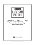
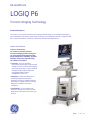
GE Healthcare
LOGIQ P6
TruScan Imaging Technology
Product Description
The LOGIQTM P6 is a premium performance, highly mobile and easy to use multipurpose imaging
system designed for obstetrics, gynecology, cardiology, musculoskeletal, vascular, urological, small
parts, superficial, pediatric, neonatal, transcranial, and abdominal applications.
System Architecture
TruScanTM Architecture our exclusive, software-intensive
ultrasound imaging platform that gives
you unsurpassed computational power,
image-manipulation capability, workflow
flexibility and product upgrade-ability,
via software or hardware.
• TruAccess - is the GE-exclusive,
raw-data processing technology that will
change the future of ultrasound imaging.
By accessing raw data, TruScan achieves
excellent image quality and ensures
unsurpassed today’s image
management tomorrow.
• SmartScan - utilizes new advances in
operating algorithms and system
operations to improve image acquisition
and patient throughput while increasing
diagnostic confidence and exam
consistency.
• ComfortScan - our most advanced
ergonomic design ever, helps maximize
productivity and simplify every exam you
perform.
LOGIQ P6
Page
1
of 14
General Specification
Dimensions and Weight
• Height:
- Maximum 1470
- Minimum 1250
• Width: 43cm
• Depth: 64cm
• Weight: approx. 80 kg (176 lb.)
Electrical Power
• Voltage: 100-120Vac or 220-240Vac
• Frequency: 50/60 Hz
• Power: Max. 750 VA with Built-in and
On-Board Peripherals
• Maximum Thermal Output: 2200
BTU/hr.
Console Design
•
•
•
•
•
•
•
•
•
3 Active Probe Ports
Integrated HDD (Capacity : 80GB)
Integrated DVD-R/W Drive
On-board Storage for Peripherals (max
3 peripherals)
- B/W-printer, color printer, DVD video
recorder
Wheels
- Wheel diameter: 12.5cm
- Integrated locking mechanism that
provides rolling lock and optional
caster swivel lock
Probe Holders, Removable for Cleaning
and Washing
Gel Holder, Removable for Cleaning
and Washing
Air Filters, Easily Removable
Front Handle
Monitor
• 17 inch TFT LCD depending on region
• XGA Format:
- Display size: 1024 x 768
• Tilt/Rotate/Translate
- Tilt Angle +40°- -90°
- Rotate Angle: +/-90°
- Translate Horizontal +/- 442 mm
- Translate Vertical 160 mm
• Flexible Arm for Monitor Translation in
X,Y, and Z axis
• Digital Brightness/Dim Bright/Contrast
Adjustment
System Overview
Applications
•
•
•
•
•
•
•
•
•
•
•
•
•
Abdominal
Obstetrical
Gynecological
Cardiac
Musculoskeletal
Vascular
Urological
Small Parts and Superficial
Breast
Pediatric and Neonatal
Transcranial
Endocavitary
Transesophageal
Scanning Methods
•
•
•
•
Electronic Sector
Electronic Convex
Electronic Linear
Mechanical Volume Sweep
User Interface
Operator Keyboard
Width: 43cm
Height: 84 - 90cm
Alphanumeric Keyboard
Ergonomic Hard Key Operations
Indicator Lights Identify Activated Keys
Integrated Recording Keys for Remote
Control of Up to 2 Peripheral Devices
and DICOM Devices
• 8 TGC Pods, with Re-mapping
Functionality at Any Depth
•
•
•
•
•
•
LOGIQ P6
Transducer Types
•
•
•
•
•
•
•
Sector Phased Array
Convex Array
Microconvex Array
Linear Array
Single CW (Pencil) Probes
Bi-plane Microconvex Array
4D Volume Probes
Operating Modes
•
•
•
•
•
• Power Doppler Imaging (PDI) with
Directional Map
• PW Doppler with High PRF
• M-Color Flow Mode
• Anatomical M-Color Mode (option)
• B-Flow Mode (option)
• Coded Contrast Imaging (option)
• CW Doppler Mode (option)
• 3D/4D Volume Modes (option)
• 3D Static
• 4D Real Time
System Standard Features
• Hard Disk for image storage
• Without compression:
• Raw DICOM: > 14500 images
• DICOM:
- Image Only: > 16,000 images
• <1000 Frames (60 sec) CINE Memory
(256MB)
• Real-time Triplex Mode at any Depth
and PRF
• Automatic Optimization
- Auto Tissue Optimization: ATO
- Auto Spectrum Optimization: ASO
- Auto Color Optimization: ACO
• CHI, Coded Harmonic Imaging
• PHI, Phase inversion Harmonics
• Coded Excitation
• SRI Speckle reduction imaging
• CRI CrossBeam
• Virtual Convex
• Patient Information Database
• Image Archive on Hard Drive and DVD
• Easy Backup to Media for data security
• TruAccess, Raw Data Processing and
Analysis
• Vascular Calcs
• Cardiac Calcs
• OB Calcs
• Fetal Trending
• Multi Gestational Calcs
• Hip Dysplasia Calcs
• Gynecological Calcs
• Urological Calcs
• Renal Calcs
• Real-time Auto Doppler Calculations
• On-board basic Reporting
B-Mode
Coded Harmonic Imaging
M-Mode
Anatomical M-Mode (option)
Color Flow Mode (CFM)
Page 2
of
14
System Options
•
•
•
•
•
•
•
•
•
•
•
•
•
•
•
•
•
Easy 3D
Advanced 3D, with 3D Landscape
DICOM 3.0 Connectivity
LOGIQView
B-Flow
Coded Contrast Imaging
Anatomical M-Mode
Real Time 4D
Report Designer (on-board reporting)
ECG
ECG Cable
Steering CW/Single CW Assy
3-Pedal Foot Switch, with
Programmable Functionality
Rear Handle
Drawer
Probe Cable Hanger
Urology Probe Holder
• Colorized Image
- Colorized B
- Colorized M
- Colorized PW
- Colorized CW (option)
• Time line Display
- Independent Dual B/PW Display
- Display Formats:
Top/ Bottom or Side/ Side selectable
Format Size: (able to switch after
freeze)
- Vertical: 1/3, ½, 2/3
- Horizontal: ¼, ½
- Full: Time line only
- Update mode: timed based on
sweep
• Virtual Convex
• CrossBeam
Display Annotation
Media & Peripheral Options
• Integrated Mounting Kits and Remote
Controls Provided for
- B/W Digital thermal printer
- Digital Color A6 Digital thermal printer
- Digital Color A5 Digital thermal printer
- DVD Video Recorder
Display Modes
• Simultaneous Capability
- B/PW
- B/CFM or PDI
- B/M
- B + CFM/M
- Real-time Triplex Mode
(B + CFM or PDI/PW)
- Dual B (B/B)
- Dual B + CFM or PDI
• Selectable Alternating Modes
- B/M
- B/PW
- B + CFM (PDI)/M
- B + CFM (PDI)/PW
- 3D – Mode (option)
- 3D – Color Mode (option)
- B + CW (option)
• Multi Image Split Screen
- Live and/or frozen
- B + B/CFM or PDI
- Independent Cine playback
- Quad screen format
• Zoom: Write/Read/Pan
LOGIQ P6
• Institution/Hospital Name: 25
Characters
• Date: 3 types selectable
YY/MM/DD, MM/DD/YY, DD/MM/YY
• Time: 2 types selectable
24 hours, 12 hours
• Operator Identification
• Patient Name: First, Last & Middle
name each store 64 characters. Up to
64 total characters displayed
• Patient Identification: 31 Characters
• Gestational Age from LMP/EDC/GA/BBT
• Power Output Readout
- MI: Mechanical Index
- TIS: Thermal Index Soft Tissue
- TIC: Thermal Index Cranial (Bone)
- TIB: Thermal Index Bone
• System Status (real-time or frozen)
• Probe Orientation Marker: Coincides
with a probe orientation marking on
the probe.
• Image Preview
• Gray/Color Bar
• Cine Gauge
• Measurement Summary Window
• Measurement Results Window: presettable display location
• Probe Type
• Application Name
• Imaging Parameters by Mode (current
mode highlighted)
- B/M-Mode
Imaging Frequency
Gain
Edge Enhance
Frame Averaging
•
•
•
•
•
•
•
•
•
•
•
•
Gray Map
Image Depth
Dynamic Range
Line Density
% of Power Output
- Color Flow Mode(Optional)
Doppler Frequency
Color Gain
Line Density
Frame Averaging
% of Power Output
PRF
Wall Filter
Spatial Filter
Packet Size
- PW-Mode
Doppler Frequency
Doppler Gain
% of Power Output
PRF
Wall Filter
Sample Volume Width
Dynamic Range
Sample Volume Depth
Angle Correction
Focal Zone Markers
TGC Curve: On/Off
Body Pattern: 106 types
B Scale Markers: 2 types
Depth/Width & Depth
M Scale Markers:
Time/Depth
Image Management Menu: Menu,
Delete, and Image Manager
Image Palette
Caps Lock: On/Off
System Messages Display
Trackball Functionality Status: Scroll,
M&A (Measurement and Analysis),
Position, Size, Scan Area Width and Tilt
Biopsy Guide Line and Zone
Heart Rate
General System Parameter
System Setup
• Diagnostic Categories: 8 types, presettable
Abd, Obst, Gyn, Card, Vasc, Urol, Small
partsts, Pediatrics
• User Programmable Preset Capability
• Factory Default Preset Data
• Languages: Chinese, Czech, Danish,
Dutch, English, Finnish, French,
German, Hungarian, Italian, Japanese,
Norwegian, Polish, Russian, Spanish,
Swedish
• Operation Error Beep: Off, Low, Loud
• Body Surface Area: 2 types
Page 3
of
14
Oriental, Occidental
• OB Report Format: 4 types
Tokyo Univ., Osaka Univ., USA, Europe
• EFBW: 8 types
Tokyo Univ., Osaka Univ., USA and
Europe (Shephard, Merz,
Hadlock/Shephard, Williams, Brenner)
• CUA/AUA for Hadlock
• Body Pattern Copy to Active Side:
On/Off
• Colorized B/M/D: 6 types for each
• Programmable Annotation Library:
24 annotations
• Customized Common Home Position
• Color Printer Memory: 3 types
Single, Quad-Frm, Quad-Frmls
• Menu Selection at New Patient: 2 types
Patient Entry, Schedule
• Sort Criteria for Schedule List: 2 types
Date&Time, Name
• Patient Name Format: 2 types
Full Name, Last&First
• Auto Deletion of Transferred Queue:
Yes/No
• Pre-settable Doppler Audio Volume
• Measurement Clear Operation: 2 types
Meas.-only, with-Comment
• Display Unit Age: 5 types
Year, Month, Week, Day, No display
• System Boot Up: 90 sec
• Probe Change: 5 sec
Complete User Manual available on
board through Help (F1)
User Manual and Service Manual are
included on CD with each system. A
printed Manual is available upon request.
CINE Memory/Image Memory
• <1000 Frames (60 sec) with Standard
CINE Memory (256 MB) depend on FOV,
Scanning Lines etc.
• CINE Gauge and CINE Image Number
Display
• CINE Review:
Frame-by-frame, Loop
• CINE Review Speed: 20 steps
(10, 20, 30, 40, 50, 60, 70, 80, 90, 100,
150, 200, 300, 400, 500, 600, 700, 800,
900, 1000%)
• Selectable CINE Sequence for CINE
Review
• Start and End Frame Selections for
Loop Playback
• Measurements, Calculations and
Annotations on CINE Playback
• Scrolling Timeline Memory
LOGIQ P6
• Cine Capture Function
• Pre-settable ECG Position
• Adjustable ECG Gain Control
Image Storage
• On-board database of patient
information from past exams
• Storage Format: DICOM/Raw Data
• DICOM Still Image Storage Size:
• Gray Image: ~300K to ~1.3 MB
• Color Image: ~900K to 1.9 MB
• Multi-frame
• Display Format: Full size, 4x4, and
"thumbnails"
• Live image and stored image side-byside display
• CD-R storage: 650, 700 MB
• Conversion to JPEG, AVI (SaveAs) and
WMV (MPEGvue) file formats
• Internal Hard Drive Image Storage:
25 GB
• External USB 2.0 Hard Drive support
for Import, Export, DICOM Read,
SaveAs, MPEGVue and EZ
Backup/EZMove
• USB 2.0 Memory Stick support for
SaveAs, USB QuickSave and MPEGVue
• Network Storage support for Import,
Export, DICOM Read, SaveAs,
MPEGVue and USB QuickSave
Connectivity
• Ethernet Network Connection
• USB serial data output (need a
converter cable)
• DICOM Support (option)
- Verify
- Print
- Store
- Modality Worklist
- Multiframe
- Storage Commitment
- Modality Performed Procedure Step
(MPPS)
- Media Exchange
- Off network/mobile storage queue
- Query/Retrieve
- Structure Reporting
- Public SR Template
- Media Store of SR
- iLinqTM capability
Physiological Input Panel (Option)
• Physiological Input
- ECG, 1 channel
• Dual R-Trigger
• Pre-settable ECG R Delay Time
Scanning Parameters
• Digital Beamformer
• 14336 System Processing Channel
Technology
• Displayed Imaging Depth: 2 – 30 cm
probe dependent
• Minimum Depth of Field: 2 cm
(Zoom and probe dependent)
• Maximum Depth of Field: 30 cm
(probe dependent)
• Transmission Focus
- 1 – 8 Focus Points Selectable (probe
and application dependent)
- Focal Zone Position, B-Mode 16 steps,
CFM 64 steps
• Continuous Dynamic Receive
Focus/Aperture
• Multi-Frequency/Wideband
Technology
• 256 Shades of Gray
• Up to 197 dB Processing Dynamic
Range
• Adjustable Field of View (FOV)
• Image Reverse: Right/Left
• Image Rotation: 4 steps
• Rotation: 0°, 90°, 180° and 270°
B-Mode
• B/M Acoustic Output: 0 – 100%, 2 %
step
• Image Reverse: On/Off
• B Color: 8 types
• Thermal Index: TIC, TIS, TIB
• Softener: 4 steps
• Focus Number: 8 steps
• Focus Width: 3 types
• Range Focus: On/Off
• Compress: 0.5 – 1.5 dB, 0.1 dB step
• Line Density: 4 steps
• Noise Suppression: 6 steps
• Frame Average: 6 steps
• Max Frame rate > 800 f/s
• Edge Enhance: 6 steps
• Angle/Width (deg, mm): probe
dependent, 10 – 170°, 2° step in case
of E8CS probe
• Gray Scale Map: 23 types
• Gain: 0 – 98 dB, 2 dB step
Page 4
of
14
• Dynamic Range: 30 – 120 dB, 3 dB step
• Harmonic Start: On/Off default presettable
• Virtual Convex: On/Off
• Depth: 2 – 30 cm, 1 cm step (probe
dependent)
• Focus Depth: 91 steps default presettable
• Rejection: 6 steps
• Frequency: 3-4 steps (probe
dependent)
• Dual Beam: On/Off pre-settable
• Steered Linear: +/- 15°
• Auto Line Density: On/Off pre-settable
Color Flow Mode
•
•
•
•
•
•
•
•
•
•
•
•
•
•
•
•
•
•
•
•
•
•
•
Base Line: 0 – 100 %, 10 % step
Invert: On/Off
Capture: 4 steps pre-settable
CF/PDI Focus Depth: 10 – 100 %, 5 %
step default pre-settable
CF/PDI ACE: On/Off
CF/PDI Acoustic Output: 0 – 100%, 10%
step
PW/CF/PDI Angle Steer: +/- 10°, 20°
(linear probe)
Packet Size: 5 -16, dependent on
probe/applications
Line Density: 5 steps
Frame Average: 7 steps
PRF: 300 Hz – 10400 Hz (probe
dependent)
Spatial Filter: 6 steps (application
dependent)
Gain: 0 – 40 dB, 0.5 dB step
Wall Filter: 7 steps depend on probe
Virtual Convex: On/Off
Angle/Width (deg, mm): probe
dependent
CFM Window Size (depends on probe)
• Convex 10° - 170°
• Sector 10° - 90°
• Linear 10 – 46mm
CF/PDI Frequency: 2 steps
Color Map: 13 types (probe
dependent)
• Velocity: 7 types
• Velocity/Variance: 3 types
• Additional: 3 types
Color Threshold: 0 – 100 %, 5 % step
Auto Line Density: On/Off pre-settable
CFM/PWD Ratio: 1, 2, 4
Accumulation Mode: 8 steps
LOGIQ P6
• Symmetrical Velocity Imaging for
optimized 3D color images
PDI-Mode
• PDI Map: 13 types
• CF/PDI Flash Suppression: 2 steps
• CF/PDI Focus Depth: 11 steps default
pre-settable
• CF/PDI Acoustic Output: 0 – 100%, 10%
step
• PW/CF/PDI Angle Steer: +/- 10°,20°
(linear probe)
• Packet Size: 5 -16, dependent on
probe/applications
• Spatial Filter: 6 steps (probe
dependent)
• Frame Average: 7 steps
• PRF: 300 Hz – 10400 Hz (probe
dependent)
• Power Threshold: 0 – 100 %, 5 % step
• CFM Window Size (depends on probe)
• Convex 10° - 133°
• Sector 10° - 90°
• Linear 10 – 46mm
• Gain: 0 – 40 dB, 0.5 dB step
• Wall Filter: 7 steps depend on probe
• CF/PDI Frequency: 2 steps
• Auto Line Density: On/Off pre-settable
• CFM/PWD Ratio: 1, 2, 4
• Transparent: 5 steps
• Invert On/Off
• Accumulation: 6 steps
M-Mode
• Sweep Speed: 8 steps
• M Color: 8 types
• M/PW Display Format: V-1/3B, V-1/2B,
V-2/3B, H-1/2B, H-1/4B, Timeline only
• B/M Acoustic Output: 0 – 100 %, 2 %
step
• Rejection: 6 steps
• Dynamic Range: 30 – 120 dB, 3 dB step
• Edge Enhance: 6 steps
• Gray Scale Map: 23 types
• M Gain: 0 – 98 dB, 2 dB step
Anatomical M-Mode
• M-mode cursor adjustable at any
plane
• Can be activated from a CINE loop
from a live or stored image
• Available with Color Flow Mode
• M & A capability
PW/CW-Mode
• Maximum and Minimum Velocity
Scales
- Max: 20 m/sec (angle/probe
dependent)
- Min: 10 cm/sec
• Gray Scale Map: 4 types
• Dynamic Range: 24 – 48, 4 dB step
• Base Line: 0 – 100 %, 10 % step
• SV Gate: 1, 2, 3, 4, 5, 6, 7, 8, 9, 10, 12, 14,
16 mm
• Angle Correct: +/- 90°, 1° step
• Spectral Color: 5 types
• PW Sweep Speed: 8 steps
• Invert: On/Off
• M/PW Display Format: V-1/3B, V-1/2B,
V-2/3B, H-1/2B, H-1/4B, Timeline only
• Duplex: On/Off
• PW Acoustic Output: 0 – 100 %, 10 %
step
• Spectral Averaging: 5 steps presettable
• Time Resolution: 4 steps
• CFM/PWD Ratio: 1, 2, 4
• Rejection: 15 steps
• Gain: 0 – 32 dB, 1 dB step
• Wall Filter: 19 – 3000 Hz, 22 steps
• PW/CF/PDI Angle Steer: +/- 10°, 20°
• PRF: 640 – 19600 Hz
• Sample Volume Depth: 29 steps default
pre-settable
• CW-Mode (option) is available on the
following probes
- 3S
- 5S
- 7S
- P2D
- P6D
Coded Harmonic Imaging
• Available on the following probes:
-
4C
5CS
8C
E8CS
E8C
BE9C
9L
11L
i739L
T739
3S
5S
7S
Page 5
of
14
- 4D3C-L
- 4DE7C
- UG7C
Softener: 4 steps
Line Density: 4 steps
Suppression: 6 steps
Edge Enhance: 6 steps
Gray Scale Map: 23 types
Gain: 0 – 98 dB, 2 dB step
Dynamic Range: 30 – 120 dB, 3 dB
step
• Rejection: 6 steps
• Auto Line Density: On/Off pre -settable
• Frequency: Up to 4 steps, depend on
probe
•
•
•
•
•
•
•
B-Flow (option)
• Available on the following probes:
- 9L
- 11L
- i739L
- T739
•
•
•
•
•
•
•
•
•
•
•
•
•
I Background: On/Off
Sensitivity/PRI: 14 steps
Line Density: 4 steps
Edge Enhance: 6 steps
Frame Average: 8 steps
Gray Scale Map: 23 types
Dynamic Range: 30 – 120 dB, 3 dB step
Rejection: 6 steps
Gain: 0 – 98 dB, 2 dB step
Auto Line Density: On/Off pre-settable
Dual Beam: On/Off pre-settable
B-Flow Color: 8 color maps
Accumulation: 6 steps
Coded Excitation
• Available on the following probes:
- 8C
- E8C
- E8CS
- BE9CS
- 11L
- ERB
Coded Contrast Imaging (option)
• Available on 4C, 5CS probes
• Contrast Clock Display
• Time Trigger Scan: 0.3, 0.5 – 10 sec,
0.5sec step
• Coded Harmonic Angio
- Tissue Background Selection: 4step
• TrueAgentDetection
- 2 frequencies on 4C
• Coded Phase Inversion:
• Phase Inversion
• Gray Scale Map: 23 types
• Maximum Enhance Mode
LOGIQ P6
The LOGIQ P6 is designed for
compatibility with commercially
available ultrasound contrast agents.
Because the availability of these
agents is subject to government
regulation and approval, product
features intended for use with these
agents may not be commercially
marketed nor made available before
the contrast agent is cleared for use.
Contrast related product features
are enabled only on systems for
delivery to an authorized country or
region of use. GE Medical Systems
makes no claims concerning the
safety or effectiveness of contrast
agents.
LOGIQView (option)
•
•
•
•
•
•
•
•
•
•
Available on all probes
Extended Field of View Imaging
For use in B-Mode
LOGIQView Status
Auto detection of scan direction
Pre or post-process zoom up to 10X
Rotation
Auto best fit on monitor
Measurements in B-Mode
Up to 60 cm scan length
RealTime 4D (option)
• Acquisition Modes:
- Realtime 4D M mode
- 3D Static B-Mode
• Visualization Modes:
- 3D Rendering(diverse surface and
intensity projection modes)
- Sectional Planes (3 Section planes
perpendicular to each other)
• Render Mode:
- Surface texture, Surface Smooth,
max-, min- and X-ray (average
intensity projection), Mix Mode of
two render Modes
• Curved 3 point render start
• 3D Movie
• Scalpel: 3D Cut tool
• Display Format:
- Quad: A-/B-/C-Plane/3D
- Dual: A-Plane/3D
- Single: 3D or A- or B- or C-Plane
• 4D Volume Frames/sec: max: 30
• Automated Volume Calculation -VOCAL
II (Option)
Virtual Convex
• Available on the Following Probes
- 8L
- 9L
- 11L
- 3S
- i739L
- T739
- ERB
CrossBeam
• Provides Spatial Compounding
• Provides 3 or 5 angles of spatial
compounding
• Live Side by Side Display
• Compatible with PHI and CHI Harmonic
Imaging
• Available on the following probes:
- 4C
- 5CS
- 8C
- E8CS
- E8C
- BE9CS
- 8L
- 9L
- 11L
- i739L
- T739
- 4D3C-L
- 4DE7C
SRI
•
•
•
•
Speckle Reduction Imaging
Provides 5 levels of speckle reduction
Live Side by Side Display
Compatible with all Convex, Linear and
Sector probes
• Compatible with all imaging modes
• Side by Side Display with Noncompounding Image
Pre-Processing
• Acoustic Power Output
• Write Zoom up to 8x
• B/M-Mode
- Gain
- TGC
- Image Reverse
- Depth
- Scan Area
- Auto Optimize (ATO)
- Dynamic Range
Page 6
of
14
- Focus Number
- Focus Position
- Line Density
- Frequency
- Image Rotation
- Gray Map
- Colorize
- Frame Average
- Edge Enhance
- Rejection
- Virtual Convex
- Focus Width
- Suppression
- B Softener
- M/D Cursor
- Sweep Speed for M-Mode
• PW-Mode
- Gain
- Sample Volume Depth
- PRF
- Wall Filter
- Baseline
- Angle Steer
- Angle Correct
- Quick Angle Correct
- Auto Angle Correct
- Doppler Frequency
- Doppler Invert
- Display Format
- Sweep Speed
- Full Timeline
- Rejection
- Time Resolution
- Gray Map
- Colorize
- Dynamic Range
- CFM/PWD Ratio
- Duplex
- Auto Calcs
- Trace Direction
- Modify Calcs
- Number of Average Cycles
- Trace Method
- Trace Sensitivity
- Auto Optimize (ASO)
- Audio Volume
• Color Flow Mode(Optional)
- Gain
- ROI Position, Size
- PRF
- Wall Filter
- Baseline
- Angle Steer
- Color Line Density
LOGIQ P6
- Color Frequency
- Packet Size
- Color Invert
- Color Map
- Threshold
- Frame Average
- Focus Position
- ACE
- Spatial Filter
- CFM/PWD Ratio
- Duplex
- Sweep Speed for Color M-Mode
- Anatomical Color M-Mode
• 3D Acquisition
- Scan Distance
- ROI Style
- Display Format
- Scan Plane
Front to Back
Side to Side
- Acquisition Mode
Parallel
Sweep
•
•
•
Post-Processing w/TruAccess (Raw
Data)
• SRI- 5 Selectable level
• Read Zoom up to 8x
• B/M-Mode
- Gain
- Dynamic Range
- TGC
- Image Reverse
- Auto Tissue Optimize (ATO)
- Compression
- Image Rotation
- Gray Map
- Colorize
- Frame Average (in loop images)
- Rejection
- Sweep Speed for M-Mode
- Anatomical M-Mode
• PW/CW-Mode
- Post Gain
- Baseline
- Angle Correct
- Quick Angle Correct
- Doppler Invert
- Display Format
- Sweep Speed
- Full Timeline
- Rejection
- Gray Map
•
- Colorize
- Compression (Dynamic Range)
- Auto Optimize (ASO)
Color Flow Mode
- Auto Color Optimization (ACO)
- Baseline
- Color Invert
- Color Map
- Threshold
- Frame Average (in loop images)
- Sweep Speed for Color M-Mode
- Anatomical Color M-Mode
Easy 3D (option)
- Colorize
- Threshold (Opacification)
- Mix Type 1
- Render
- Texture
- Gray Surface
- Scalpel
- Auto Movie
- Undo
- Reset
Advanced 3D (option)
- 3D Landscape
- Colorize
- Threshold (Opacification)
- Re-slice
- Type 1/2
- Group Planes
- Scalpel
- Define Axis
- Visible Data
- Tile
- Active Data
- Auto Movie
- Rotate
- Undo
- Reset
3D Movie
- Colorize
- Pause
- Movie Speed
- Axis
- Define Start/End
- Auto Movie
- Movie 360°
- Manual
Measurements / Calculations
General B-Mode
• Depth & Distance
• Circumference (Ellipse / Trace)
• Area (Ellipse / Trace)
Page 7
of
14
• Volume (Ellipsoid)
• % Stenosis (Area or Diameter)
• Angle between two lines
General M-Mode
•
•
•
•
•
M-Depth
Distance
Time
Slope
Heart Rate
General Doppler
Measurements/Calculations
•
•
•
•
•
•
•
•
•
•
•
•
•
•
Velocity
Time
A/B Ratio (Velocities / Frequency Ratio
PS (Peak Systole)
ED (End Diastole)
PS/ED (PS/ED Ratio)
ED/PS (ED/PS Ratio)
AT (Acceleration Time)
ACCEL (Acceleration)
TAMAX (Time Averaged Maximum
Velocity
Volume Flow (TAMEAN and Vessel
Area)
Heart Rate
PI (Pulsatility Index)
RI (Resistivity Index)
Real-time Doppler Auto
Measurements / Calculations
PS (Peak Systole)
ED (End Diastole)
MD (Minimum Diastole)
PI (Pulsatility Index)
RI (Resistivity Index)
AT (Acceleration Time)
ACC (Acceleration)
PS/ED (PS/ED Ratio)
ED/PS (ED/PS Ratio)
HR (Heart Rate)
TAMAX (Time Averaged Maximum
Velocity)
• PVAL (Peak Velocity Value)
• Volume Flow (TAMEAN and Vessel
Area)
•
•
•
•
•
•
•
•
•
•
•
OB Measurements/Calculations
• Gestational Age by:
- GS (Gestational Sac)
- CRL (Crown Rump Length)
- FL (Femur Length)
- BPD (Biparietal Diameter)
- AC (Abdominal Circumference)
- HC (Head Circumference)
- APTD x TTD (Anterior/Posterior Trunk
Diameter by Transverse Trunk
LOGIQ P6
•
•
•
•
•
•
•
•
•
•
•
•
•
Diameter)
- LV (Length of Vertebra)
- FTA (Fetal Trunk Cross-sectional Area)
- HL (Humerus Length)
- BD (Binocular Distance)
- FT (Foot Length)
- OFD (Occipital Frontal Diameter)
- TAD (Transverse Abdominal Diameter)
- TCD (Transverse Cerebellum
Diameter)
- THD (Thorax Transverse Diameter)
- TIB (Tibia Length)
- ULNA (Ulna Length)
Estimated Fetal Weight (EFW) by:
- AC, BPD
- AC, BPD, FL
- AC, BPD, FL, HC
- AC, FL
- AC, FL, HC
- AC, HC
Calculations and Ratios
- FL/BPD
- FL/AC
- FL/HC
- HC/AC
- CI (Cephalic Index)
- AFI (Amniotic Fluid Index)
Nuchal Translucency Measurement
Nosalbone Measurement
Measurements / Calculations by:
Jeanty, Merz, Tokyo University, Mercer,
Hansmann, Erickson, Hill, Shephard,
Hadlock, Hohler, Campbell
Fetal Graphical Trending
Growth Percentiles
Multi-Gestational Calculations (4)
Fetal Qualitative Description
(Anatomical survey)
Fetal Environmental Description
(Biophysical profile)
Programmable OB Tables
Over 20 selectable OB Calcs
Expanded Worksheets
GYN Measurements/Calculations
•
•
•
•
•
•
•
•
•
Right Ovary Length, Width, Height
Left Ovary Length, Width, Height
Uterus Length, Width, Height
Ovarian Volume
ENDO (Endometrial thickness)
Ovarian RI
Uterine RI
Follicular measurements
Summary Reports
Vascular
Measurements/Calculations
• SYS DCCA (Systolic Distal Common
Carotid Artery)
• DIAS DCCA (Diastolic Distal Common
Carotid Artery)
• SYS MCCA (Systolic Mid Common
Carotid Artery)
• DIAS MCCA (Diastolic Mid Common
Carotid Artery)
• SYS PCCA (Systolic Proximal Common
Carotid Artery)
• DIAS PCCA (Diastolic Proximal Common
Carotid Artery)
• SYS DICA (Systolic Distal Internal
Carotid Artery)
• DIAS DICA (Systolic Distal Internal
Carotid Artery)
• SYS MICA (Systolic Mid Internal Carotid
Artery)
• DIAS MICA (Diastolic Mid Internal
Carotid Artery)
• SYS PICA (Systolic Proximal Internal
Carotid Artery)
• DIAS PICA (Diastolic Proximal Internal
Carotid Artery)
• SYS DECA (Systolic Distal External
Carotid Artery)
• DIAS DECA (Diastolic Distal External
Carotid Artery)
• SYS PECA (Systolic Proximal External
Carotid Artery)
• DIAS PECA (Diastolic Proximal External
Carotid Artery)
• VERT (Systolic Vertebral Velocity)
• SUBCLAV (Systolic Subclavian Velocity)
• Summary Reports
• Mean IMT Measurement Tools
Cardiac
Measurements/Calculations
• Cardiac calculation package including
extensive measurements and display
of multiple repeated measurements
• Parameter annotation follow ASE
standard
* See Supplement for details
Report Writer (Optional)
• On-board reporting package
automates report writing
• Formats various exam results into a
report suitable for printing to a
windows printer or reviewing on a
standard PC
• Exam results include patient info, exam
info, measurements, calculations,
images, comments and diagnosis
• Standard templates provided
Page 8
of
14
• Customizable templates
Supplement:
Cardiac
Measurements/Calculations
B-Mode Measurements
• Aorta
- Aortic Root Diameter (Ao Root Diam)
- Aortic Arch Diameter (Ao Arch Diam)
- Ascending Aortic Diameter (Ao Asc)
- Descending Aortic Diameter (Ao Desc
Diam)
- Aorta Annulus Diameter (Ao Annulus
Diam)
- Aorta Isthmus (Ao Isthmus)
- Aorta *** (Ao st junct)
• Aortic Valve
- Aortic Valve Cusp Separation (AV
Cusp)
- Aortic Valve Area Planimetry (AVA Pl
ani met ry)
- *** ( Trans AVA)
• Left Atrium
- Left Atrium Diameter (LA Diam)
- LA Length (LA Major)
- LA W idth (LA Minor)
- Left Atrium Diameter to AoRoot
Diameter Ratio (LA/Ao Ratio)
- Left Atrium Area (LAA(d), LAA(s))
- Left Atrium Volume, Single Plane,
Method of Disk (LAEDV A2C, LAESV
A2C ) (LAEDV A4C, LAESV A4C)
• Left Ventricle
- Left Ventricle Mass (LVPWd, LVPWs)
- Left Ventricle Volume, Teichholz/Cubic
(LVIDd, LVI Ds)
- Left Ventricle Internal Diameter (LVIDd,
LVI Ds)
- Left Ventricle Length (LVLd, LVLs)
- Left Ventricle Outflow Tract Diameter
(LVOT Diam)
- Left Ventricle Posterior Wall Thickness
(LVPWd, LVPWs)
- Left Ventricle Length (LV Major)
- Left Ventricle Width (LV Minor)
- Left Ventricle Outflow Tract Area
(LVOT)
- Left Ventricle Area, Two
Chamber/Four Chamber/Short Axis
(LVA (d), LVA (s))
- Left Ventricle Endocardial Area, Width
(LVA (d), LVA(s))
- Left Ventricle Epicardial Area, Length
LOGIQ P6
•
•
•
•
(LVAepi (d), LVAepi (s))
- Left Ventricle Mass Index (LVPWd,
LVPWs)
- Ejection Fraction, Teichholz/Cube
(LVIDd, LVIDs)
- Left Ventricle Posterior Wall Fractional
Shortening (LVPWd, LVPWs)
- Left Ventricle Stroke Index,
Teichholz/Cube (LVIDd, LVIDs, and
Body Surface Area)
- Left Ventricle Fractional Shortening
(LVIDd, LVIDs)
- Left Ventricle Stroke Volume,
Teichholz/Cubic (LVIDd, LVIDs)
- Left Ventricle Stroke Index, Single
Plane, Two Chamber, Method of Disk
(LVI Dd, LVIDs, LVSd, LVSs)
- Left Ventricle Stroke Index, Single
Plane, Four Chamber, Method of Disk
(LVI Dd, LVIDs, LVSd, LVSs)
- Left Ventricle Stroke Index, Bi-Plane,
Bullet, Method of Disk (LVAd, LVAs)
- Interventricular Septum (IVS)
- Left Ventricle Internal Diameter (LVI D)
- Left Ventricle Posterior Wall Thickness
(LVPW)
Mitral Valve
- Mitral Valve Annulus Diameter (MV
Ann Diam)
- E-Point-to-Septum Separation (EPSS)
- Mitral Valve Area by Pressure Half
Time (MVA By PHT)
- Mitral Valve Area Planimetry (MVA
Planimetry)
Pulmonic Valve
- Pulmonic Valve Area (PV Planimetry)
- Pulmonic Valve Annulus Diameter (PV
Annulus Diam)
- Pulmonic Diameter (Pulmonic Diam)
Right Atrium
- Right Atrium Diameter, Length (RAD
Ma)
- Right Atrium Diameter, Width (RAD Mi)
- Right Atrium Area (RAA)
- Right Atrium Volume, Single Plane,
Method of Disk (RAAd)
- Right Atrium Volume, Systolic, Single
Plane, Method of Disk (RAAs)
Right Ventricle
- Right Ventricle Outflow Tract Area
(RVOT Planimetry)
- Left Pulmonary Artery Area (LPA Area)
- Right Pulmonary Artery Area (RPA
Area)
- Right Ventricle Internal Diameter
(RVIDd, RVIDs)
- Right Ventricle Diameter, Length (RVD
Ma)
- Right Ventricle Diameter, Width (RVD
Mi)
- Right Ventricle Wall Thickness
(RVAWd, RVAWs)
- Right Ventricle Outflow Tract
Diameter (RVOT Diam)
- Left Pulmonary Artery (LPA)
- Main Pulmonary Artery (MPA)
- Right Pulmonary Artery (RPA)
• System
- Interventricular Septum Thickness
(IVSd, IVSs)
- Inferior Vena Cava
- Pulmonary Artery Diameter (MPA)
- Systemic Vein Diameter (Systemic
Diam)
- Patent Ductus Arterosis Diameter
(PDA Diam)
- Pericard Effusion (PEs)
- Patent Foramen Ovale Diameter (PFO
Diam)
- Ventricular Septal Defect Diameter
(VSD Diam)
- Interventricular Septum (IVS)
Fractional Shortening (IVSd, IVSs)
• Tricuspid Valve
- Tricuspid Valve Area (TV Panimetry)
- Tricuspid Valve Annulus Diameter (TV
Annulus Diam)
M-Mode Measurements
• Aorta
- Aortic Root Diameter (Ao Root Diam)
• Aortic Valve
- Aortic Valve Diameter (AV Diam)
- Aortic Valve Cusp Separation (AV
Cusp)
- Aortic Valve Ejection Time (LVET)
• Left Atrium
- Left Atrium Diameter to AoRoot
Diameter Ratio (LA/Ao Ratio)
- Left Atrium Diameter (LA Diam)
• Left Ventricle
- Left Ventricle Volume, Teichholz/Cubic
(LVIDd, LVI Ds)
- Left Ventricle Internal Diameter (LVIDd,
LVI Ds)
- Left Ventricle Posterior Wall Thickness
(LVPWd, LVPWs)
- Left Ventricle Ejection Time (LVET)
Page 9
of
14
•
•
•
•
•
- Left Ventricle Pre-Ejection Period
(LVPEP)
- Interventricular Septum (IVS)
- Left Ventricle Internal Diameter (LVI D)
- Left Ventricle Posterior Wall Thickness
(LVPW)
Mitral Valve
- E-Point-to-Septum Separation (EPSS)
- Mitral Valve Leaflet Separation (D-E
Excursion)
- Mitral Valve Anterior Leaflet Excursion
(D-E Excursion)
- Mitral Valve D-E Slope (D-E Slope)
- Mitral Valve E-F Slope (E-F Slope)
Pulmonic Valve
- QRS complex to end of envelope (Qto-PV close)
Right Ventricle
- Right Ventricle Internal Diameter
(RVIDd, RVIDs)
- Right Ventricle Wall Thickness
(RVAWd, RVAWs)
- Right Ventricle Outflow Tract
Diameter (RVOT Diam)
- Right Ventricle Ejection Time (RVET)
- Right Ventricle Pre-Ejection Period
(RVPEP)
- Velocity Circumferential Fiber
Shortening (Vcf)
System
- Interventricular Septum Thickness
(IVSd, IVSs)
- Pericard Effusion (PE(d))
- Interventricular Septum (IVS)
Fractional Shortening (IVSd, IVSs)
Tricuspid Valve
- QRS complex to end of envelope (Qto-TV close)
Doppler Mode Measurements
• Aortic Valve
- Aortic Insufficiency Mean Pressure
Gradient (AR Trace)
- Aortic Insufficiency Peak Pressure
Gradient (AR Vmax)
- Aortic Insufficiency End Diastole
Pressure Gradient (AR Trace)
- Aortic Insufficiency Mean Velocity (AR
Trace)
- Aortic Insufficiency Mean Square Root
Velocity (AR Trace)
- Aortic Insufficiency Velocity Time
Integral (AR Trace)
- Aortic Valve Mean Velocity (AV Trace)
LOGIQ P6
- Aortic Valve Mean Square Root
Velocity (AV Trace)
- Aortic Valve Velocity Time Integral (AV
Trace)
- Aortic Valve Mean Pressure Gradient
(AV Trace)
- Aortic Valve Peak Pressure Gradient
(AR Vmax)
- Aortic Insufficiency Peak Velocity (AR
Vmax)
- Aortic Insufficiency End-Diastolic
Velocity (AR Trace)
- Aortic Valve Peak Velocity (AV Vmax)
- Aortic Valve Peak Velocity at Point E
(AV Vmax)
- Aorta Proximal Coarctation (Coarc
Pre-Duct)
- Aorta Distal Coarctation (Coarc PostDuct)
- Aortic Valve Insufficiency Pressure
Half Time (AR PHT)
- Aortic Valve Flow Acceleration (AV
Trace)
- Aortic Valve Pressure Half Time (AV
Trace)
- Aortic Valve Acceleration Time (AV
Acc Ti me)
- Aortic Valve Deceleration TIme (AV
Trace)
- Aortic Valve Ejection Time (AVET)
- Aortic Valve Acceleration to Ejection
Time Ratio (AV Acc Time, AVET)
- Aortic Valve Area according to PHT
• Left Ventricle
- Left Ventricle Outflow Tract Peak
Pressure Gradient (VLOT Vmax)
- Left Ventricle Outflow Tract Peak
Velocity (LVOT Vmax)
- Left Ventricle Outflow Tract Mean
Pressure Gradient (LVOT Trace)
- Left Ventricle Outflow Tract Mean
Velocity (LVOT Trace)
- Left Ventricle Outflow Tract Mean
Square Root Velocity (LVOT Trace)
- Left Ventricle Outflow Tract Velocity
Time Integral (LVOT Trace)
- Left Ventricle Ejection Time (LVET)
- Cardiac Output by Aortic Flow (AVA Pl
ani met ry, AV Trace)
- Stroke Volume Index by Aortic Flow
(AVA Planimetry, AV Trace)
• Mitral Valve
- Mitral Valve Regurgitant Flow
Acceleration (MR Trace)
- Mitral Valve Regurgitant Mean
Velocity (MR Trace)
- Mitral Regurgitant Mean Square Root
Velocity (MR Trace)
- Mitral Regurgitant Mean Pressure
Gradient (MR Trace)
- Mitral Regurgitant Velocity Time
Integral (MR Trace)
- Mitral Valve Mean Velocity (MR Trace)
- Mitral Valve Mean Square Root
Velocity (MR Trace)
- Mitral Valve Velocity Time Integral (MR
Trace)
- Mitral Valve Mean Pressure Gradient
(MR Trace)
- Mitral Regurgitant Peak Pressure
Gradient (MR Vmax)
- Mitral Valve Peak Pressure Gradient
(MR Vmax)
- Mitral Regurgitant Peak Velocity (MR
Vmax)
- Mitral Valve Peak Velocity (MR Vmax)
- Mitral Valve Velocity Peak A (MV A
Velocity)
- Mitral Valve Velocity Peak E (MV E
Velocity)
- Mitral Valve Area according to PHT
(MV PHT)
- Mitral Valve Flow Deceleration (MV
Trace)
- Mitral Valve Pressure Half Time (PV
PHT)
- Mitral Valve Flow Acceleration (MV
Trace)
- Mitral Valve E-Peak to A-Peak Ratio
(A-C and D-E) (MV E/ARatio)
- Mitral Valve Acceleration Time (MV
Acc Time)
- Mitral Valve Deceleration Time (MV
Dec Time)
- Mitral Valve Ejection Time ((MV Trace)
- Mitral Valve A-Wave Duration (MV A
Dur)
- Mitral Valve Time to Peak (MV Trace)
- Mitral Valve Acceleration
Time/Deceleration Time Ratio
(MVAcc/Dec Time)
- Stroke Volume Index by Mitral Flow
(MVA Planimetry, MVTrace)
- Mitral Valve Area from Continuity
Equation (MVAPlanimetry, LVOT Vmax,
MV Vmax)
• Pulmonic Valve
- Pulmonic Insufficiency Peak Pressure
Page 10
of 14
Gradient (PR Vmax)
- Pulmonic Insufficiency End-Diastolic
Pressure Gradient (PRTrace)
- Pulmonic Valve Peak Pressure
Gradient (PV Vmax)
- Pulmonic End-Diastolic Pressure
Gradient (PR Trace)
- Pulmonic Insufficiency Peak Velocity
(PR Vmax)
- Pulmonic Insufficiency End-Diastolic
Velocity (Prend Vmax)
- Pulmonic Valve Peak Velocity (PV
Vmax)
- Pulmonic End-Diastolic Velocity (PV
Trace)
- Pulmonary Artery Diastolic Pressure
(PV Trace)
- Pulmonic Insufficiency Mean Pressure
Gradient (PR Trace)
- Pulmonic Valve Mean Pressure
Gradient (PV Trace)
- Pulmonic Insufficiency Mean Velocity
(PR Trace)
- Pulmonic Insufficiency Mean Square
Root Velocity(PR Trace)
- Pulmonic Insufficiency Velocity Time
Integral (PR Trace)
- Pulmonic Valve Mean Velocity (PV
Trace)
- Pulmonic Valve Mean Square Root
Velocity (PV Trace)
- Pulmonic Valve Velocity Time Integral
(PV Trace)
- Pulmonic Insufficiency Pressure Half
Time (PR PHT)
- Pulmonic Valve Flow Acceleration (PV
Acc Time)
- Pulmonic Valve Acceleration Time (PV
Acc Time)
- Pulmonic Valve Ejection Time (PVET)
- Pulmonic Valve Pre-Ejection Period
(PVPEP)
- QRS complex to end of envelope (Qto-PV close)
- Pulmonic Valve Acceleration to
Ejection TIme Ratio (PV Acc Time,
PVET)
- Pulmonic Valve Pre-Ejection to
Ejection Time Ratio (PVPEP, PVET)
• Right Ventricle
- Right Ventricle Outflow Tract Peak
Pressure Gradient (RVOT Vmax)
- Right Ventricle Systolic Pressure
(RVOT Vmax)
LOGIQ P6
- Right Ventricle Outflow Tract Peak
Velocity (RVOT Vmax)
- Right Ventricle Diastolic Pressure
(RVOT Trace)
- Right Ventricle Outflow Tract Velocity
Time Integral (RVOTTrace)
- Right Ventricle Ejection Time (RV
Trace)
- Stroke Volume by Pulmonic Flow
(RVOT Planimetry, RVOTTrace)
- Right Ventricle Stroke Volume Index
by Pulmonic Flow (RVOT Planimetry,
RVOT Trace)
• System
- Pulmonary Artery Peak Velocity (PV
Vmax)
- Pulmonary Vein Velocity Peak A
(reverse) (P Vein A)
- Pulmonary Vein Peak Velocity (P Vein
D, P Vein S)
- Systemic Vein Peak Velocity (PDA
Diastolic, PDA Systolic)
- Ventricular Septal Defect Peak
Velocity (VSD Vmax)
- Atrial Septal Defect (ASD Diastolic,
ASD Systolic)
- Pulmonary Artery Velocity Time
Integral (PV Trace)
- Systemic Vein Velocity Time Integral
(PDA Trace)
- Pulmonary Vein A-Wave Duration (P
Vein A Dur)
- IsoVolumetric Relaxation Time (IVRT)
- IsoVolumetric Contraction Time (IVCT)
- Pulmonary Vein S/D Ratio (P Vein D, P
Vein S)
- Ventricular Septal Defect Peak
Pressure Gradient (VSD Vmax)
- Pulmonic-to-Systemic Flow Ratio
(Qp/Qs)
• Tricuspid Valve
- Tricuspid Regurgitant Peak Pressure
Gradient (TR Vmax)
- Tricuspid Valve Peak Pressure
Gradient (TV Vmax)
- Tricuspid Regurgitant Peak Velocity
(TR Vmax)
- Tricuspid Valve Peak Velocity (TV
Vmax)
- Tricuspid Valve Velocity Peak A (TV A
Velocity)
- Tricuspid Valve Velocity Peak E (TV E
Velocity)
- Tricuspid Regurgitant Mean Pressure
Gradient (TR Trace)
- Tricuspid Valve Mean Pressure
Gradient (TV Trace)
- Tricuspid Regurgitant Mean Velocity
(TR Trace)
- Tricuspid Regurgitant Mean Square
Root Velocity (TR Trace)
- Tricuspid Regurgitant Velocity Time
Integral (TR Trace)
- Tricuspid Valve Mean Velocity (TV
Trace)
- Tricuspid Valve Mean Square Root
Velocity (TV Trace)
- Tricuspid Valve Velocity Time Integral
(TV Trace)
- Tricuspid Valve Time to Peak (TV
Acc/Dec Time)
- Tricuspid Valve Ejection Time (TV
Acc/Dec Time)
- Tricuspid Valve A-Wave Duration (TV
A Dur)
- QRS complex to end of envelope (Qto-TV close)
- Tricuspid Valve Pressure Half Time (TV
PHT)
- Stroke Volume by Tricuspid Flow (TV
Planimetry, TV Trace)
- Tricuspid Valve E-Peak to A-Peak
Ratio (TV E/A Velocity)
Color Flow Mode Measurements
• Aortic Valve
- Proximal Isovelocity Surface Area:
Regurgitant Orifice Area (AR Radius)
- Proximal Isovelocity Surface Area:
Radius of Aliased Point (AR Radius)
- Proximal Isovelocity Surface Area:
Regurgitant Flow (AR Trace)
- Proximal Isovelocity Surface Area:
Regurgitant Volume Flow (AR Trace)
- Proximal Isovelocity Surface Area:
Aliased Velocity (AR Vmax)
• Mitral Valve
- Proximal Isovelocity Surface Area:
Regurgitant Orifice Area (MR Radius)
- Proximal Isovelocity Surface Area:
Radius of Aliased Point (MR Radius)
- Proximal Isovelocity Surface Area:
Regurgitant Flow (MR Trace)
- Proximal Isovelocity Surface Area:
Regurgitant Volume Flow (MR Trace)
- Proximal Isovelocity Surface Area:
Aliased Velocity (MR Vmax)
Page 11
of 14
Combination Mode Measurements
• Aortic Valve
- Aortic Valve Area (Ao Root Diam, LVOT
Vmax, AV Vmax)
- Aortic Valve Area by Continuity
Equation by Peak Velocity (Ao Root
Diam, LVOT Vmax, AV Vmax)
- Stroke Volume by Aortic Flow (AVA Pl
ani met ry, AV Trace)
- Cardiac Output by Aortic Flow (AVA
Planimetry, AV Trace, HR)
- Aortic Valve Area by Continuity
Equation VTI (Ao Root Diam, LVOT
Vmax, AV Trace)
• Left Ventricle
- Cardiac Output, Teichholz/Cubic
(LVIDd, LVI Ds, HR)
- Cardiac Output Two Chamber, Single
Plane, Area-Length/ Method of
Disk(Simpson) (LVAd, LVAs, HR)
- Cardiac Output Four Chamber, Single
Plane, Area-Length/ Method of
Disk(Simpson) (LVAd, LVAs, HR)
- Ejection Fraction Two Chamber,
Single Plane, Area-Length/ Method of
Disk(Simpson) (LVAd, LVAs)
- Ejection Fraction Four Chamber,
Single Plane, Area-Length/ Method of
Disk(Simpson) (LVAd, LVAs)
- Left Ventricle Stroke Volume, Single
Plane, Two Chamber/Four Chamber,
Area-Length (LVAd, LVAs)
- Left Ventricle Stroke Volume, Single
Plane, Two Chamber/Four Chamber,
Method of Disk(Simpson) (LVIDd, LVIDs,
LVAd, LVAs)
- Left Ventricle Volume, Two
Chamber/Four Chamber, Area-Length
(LVAd, LVAs)
- Ejection Fraction, Bi-Plane, Method of
Disk (LVAd, LVAs, 2CH, 4CH)
- Left Ventricle Stroke Volume, Bi-Plane,
Method of Disk (LVAd, LVAs, 2CH, 4CH)
- Left Ventricle Volume, Bi-Plane,
Method of Disk (LVAd, LVAs, 2CH, 4CH)
- Left Ventricle Stroke Index, Single
Plane, Two Chamber/Four Chamber,
Area-Length (LVSd, LVSs, and BSA)
- Left Ventricle Volume, Single Plane,
Two Chamber/Four Chamber, Method
of Disk (LVAd, LVAs)
- Left Ventricle Volume, Apical View,
Long Axis, Method of Disk (LVAd, LVAs)
- Stroke Volume by Aortic Flow (AVA
LOGIQ P6
Planimetry, AV Trace)
• Mitral Valve
- Stroke Volume by Mitral Flow (MVA
Planimetry, MV Trace)
- Cardiac Output by Mitral Flow (MVA
Planimetry, MV Trace, HR)
• Pulmonic Valve
- Stroke Volume by Pulmonic Flow (PV
Planimetry, PV Trace)
- Cardiac Output by Pulmonic Flow (PV
Planimetry, PV Trace, HR)
• Tricuspid Valve
- Cardiac Output by Tricuspid Flow (TV
Planimetry, TV Trace, HR)
Cardiac Worksheet
• Parameter : lists the mode, the
measurement folder, and the specific
measurement
• Measured Value: Up to six
measurement values for each item.
Average, maximum, minimum, or last
Generic Study in Cardiology
•
•
•
•
Stroke Volume (SV)
Flow Volume (FV)
Cardiac Output (CO)
Flow Volume Output (FVO)
Probes
• 4C Wide band Convex Probe
- Applications: Abdomen, OB Gyn,
Urology, and Vascular
- Maximum Band Width 1.4 – 5 MHz
- Number of Elements: 128
- Convex Radius: 60 mm
- FOV: 55°
- Foot Print: 60mm x 18 mm
- Fundamental Frequency: 2,3,4,5 MHz
- Harmonic Frequency: 4,5,5.2,5.5MHz
- Doppler Frequency: 2.5, 3.3 MHz
- Biopsy Guide Available: Multi Angle,
Reusable
• 5CS Wide band Convex Probe
- Applications: Abdomen, OB Gyn,
Urology, and Vascular
- Maximum Band Width: 3 – 6 MHz
- Number of Elements: 128
- Convex Radius: 60 mm
- FOV: 55°
- Foot Print: 60mm x 18 mm
- Fundamental Frequency: 2,3,5 MHz
- Harmonic Frequency: 4,5,5.2,6MHz
- Doppler Frequency: 2.5, 3.3 MHz
- Biopsy Guide Available: Multi Angle,
Reusable
• E8CS Wide Band Microconvex Probe
- Applications: OB, Gyn, Urology,
Endocavity
- Probe Band Width: 4.0 – 11.0 MHz
- Number of Element: 128
- Convex Radius: 11 mmR
- FOV (Max): 170°
- Physical Foot Print: 15 x 10 mm
- B-mode Imaging Frequency: 6.0, 8.0,
10.0 MHz
- Harmonic Frequency: 8, 10
- Doppler Frequency: 4.0, 5.0 MHz
- Biopsy Guide Available: Single Angle,
Disposable, Reusable
• E8C Wide Band Microconvex Probe
Applications: OB, Gyn, Urology,
Endocavity
Probe Band Width: 4.0 – 11.0 MHz
Number of Element: 128
Convex Radius: 11 mmR
FOV (Max): 133°
Physical Foot Print: 26 x 10 mm
B-mode Imaging Frequency: 6.0,
8.0, 10.0 MHz
Harmonic Frequency: 8, 10
Doppler Frequency: 4.0, 5.0 MHz
Biopsy Guide Available: Single
Angle, Disposable, Reusable
• 8C Wide Band Microconvex Probe
- Applications: Pediatric, Neonatal
- Probe Band Width: 4.0 – 11.0 MHz
- Number of Element: 128
- Convex Radius: 11 mmR
- FOV (Max): 133°
- Physical Foot Print: 26 x 10 mm
- B-mode Imaging Frequency: 6.0, 8.0,
10.0 MHz
- Harmonic Frequency: 8, 10
- Doppler Frequency: 4.0, 5.0 MHz
- Biopsy Guide Available: None
• BE9C Micro convex Bi-plan Probe
- Applications: urology
- Probe Band Width: 4.0 – 11.0 MHz
- Number of Element: 96
- Convex Radius: 9 mmR
- FOV (Max): 127°
Page 12
of 14
- Physical Foot Print: 25 x 10 mm
- B-mode Imaging Frequency: 6.0, 8.0,
10.0 MHz
- Harmonic Frequency: 8, 10MHz
- Doppler Frequency: 4.0, 5.0 MHz
- Biopsy Guide Available: Single Angle,
Reusable, disposal
• ERB Biplane Probe
Applications: Urology
Probe Band Width:
ERB Linear: 4.7 – 10.0 MHz
ERB Convex: 4.5 – 8.8 MHz
- Number of Element:
ERB Linear: 128 Elements
ERB Convex: 128 Elements
- Probe Radius:
ERB Convex Radius: 8 mmR
ERB Linear Radius: 0 mmR
- FOV (Max):
ERB Convex FOV (Max): 122°
ERB Linear FOV (Max): 51.2mm
- Physical Foot Print:
ERB Convex: 17 x 5.5 mm
ERB Linear: 51 x 5 mm
B-mode Imaging Frequency: 6.0,
8.0, 10.0 MHz
Harmonic Frequency: 8.0, 10.0
MHz
Doppler Frequency: 5.0, 6.7 MHz
- Biopsy Guide Available: Brachy Grid,
Bridge Biopsy Guide
• 3S Wide Band Phased Array Sector
Probe
- Applications: Cardiac, Transcranial,
Abdomen
- Probe Band Width: 1.5 – 3.5 MHz
- Number of Element: 64
- FOV (Max): 90°
- Physical Foot Print: 18.5 x 18.5 mm
- B-mode Imaging Frequency: 2.0, 2.5,
3.0 MHz
- Harmonic Frequency: 3.2, 3.6 MHz
- Doppler Frequency: 1.7, 2.0, 2.2 MHz
- St-CWD Frequency: 2.0 MHz
- Biopsy Guide Available: Multi Angle,
Reusable
• 5S Wide Band Phased Array Sector
Probe
- Applications: Cardiac, Transcranial,
Abdomen
- Probe Band Width: 2.2 – 5.3 MHz
LOGIQ P6
- Number of Element: 96
- FOV (Max): 90°
- Physical Foot Print: 14.4 x 11 mm
- B-mode Imaging Frequency: 3.0, 4.0,
5.0 MHz
- Harmonic Frequency: 4.0, 5.0 MHz
- Doppler Frequency: 2.5, 3.3 MHz
- St-CWD Frequency: 2.5 MHz
- Biopsy Guide Available: Multi Angle,
Reusable
• 7S Wide Band Phased Array Sector
Probe
- Applications: Neonatal, Abdomen,
Pediatrics
- Probe Band Width: 3.0 – 8.0 MHz
- Number of Element: 64
- FOV (Max): 90°
- Physical Foot Print: 9.3 x 7.0 mm
- B-mode Imaging Frequency: 5.0, 6.0,
7.0 MHz
- Doppler Frequency: 3.3, 4.0 MHz
- St-CWD Frequency: 4.0 MHz
- - Biopsy Guide Available: None
• 8L Wide Band Linear Probe
- Applications: Vascular, Small Parts,
Neonatal, and Pediatrics
- Probe Band Width 4– 10 MHz
Number of Element: 128
FOV (Max): 39 mm
- Physical Foot Print: 40 x 6 mm
B-mode Imaging Frequency: 6.0,
8.0, 10.0 MHz
Harmonic Frequency: 8, 10 MHz
- Doppler Frequency: 5, 6.7 MHz
- Steered Angle: +/- 10°, 20°
- Biopsy Guide Available: Multi Angle,
Reusable
• 9L Wide Band Linear Probe
- Applications: Vascular, Small Parts,
Neonatal, and Pediatrics
- Probe Band Width 3– 10 MHz
- Number of Element: 192
- FOV (Max): 44 mm
- Physical Foot Print: 44 x 6 mm
- B-mode Imaging Frequency: 6.0, 7.0,
9.0 MHz
- Doppler Frequency: 4.0, 5 MHz
- Steered Angle: +/- 10°, 20°
- Harmonic Frequency: 8, 10 MHz
- Biopsy Guide Available: Multi Angle,
Reusable
• 11L Wide Band Linear Probe
- Applications: Vascular, Small Parts,
Neonatal, Pediatrics
- Probe Band Width: 5 – 13 MHz
- Number of Element: 192
- FOV (Max): 39 mm
- Physical Foot Print: 39 x 5 mm
- B-mode Imaging Frequency: 6.0, 8.0,
10.0 MHz
- Harmonic Frequency: 8, 10, 13MHz
- Doppler Frequency: 5.0, 6.7 MHz
- Steered Angle: +/- 10°, 20°
- Biopsy Guide Available: Multi Angle,
Reusable
• T739 Intraoperative Wide Band Linear
Probe
- Applications: Intraoperative
- Probe Band Width: 3.5 – 10 MHz
- Number of Element: 192
- FOV (Max): 39 mm
- Physical Foot Print: 39 x 10 mm
- B-mode Imaging Frequency: 6.0, 8.0,
10.0 MHz
- Harmonic Frequency: 8.0, 10.0 MHz
- Doppler Frequency: 5.0, 6.7 MHz
- Steered Angle: +/- 10°, 20°
- Biopsy Guide Available: Multi Angle,
Reusable
• i739L Intraoperative Wide Band Linear
Probe
- Applications: Intraoperative
- Probe Band Width: 3.5 – 10 MHz
- Number of Element: 192
- FOV (Max): 39 mm
- Physical Foot Print: 39 x 10 mm
- B-mode Imaging Frequency: 6.0, 8.0,
10.0 MHz
- Harmonic Frequency: 8.0, 10.0 MHz
- Doppler Frequency: 5.0, 6.7 MHz
- Steered Angle: +/- 10°, 20°
- Biopsy Guide Available: None
• 4D3C-L Convex Volume Probe
- Applications: Abdomen, OB
- Probe Band Width: 2 – 5 MHz
- Number of Elements: 192
- Convex Radius: 40.5 mmR
- Volume Sweep Radius: 20,15mm
- FOV: 80° (B), 85° x 80° (Volume scan)
- Foot Print: 53.2 x 40.6 mm
- B-mode imaging Frequency: 3, 4, 5
MHz
- Harmonic Frequency: 4, 4.5, 4.8, 5.0
Page 13
of 14
MHz
- Color Frequency: 2.5, 3.3 MHz
- Doppler Frequency: 2.5, 3.3 MHz
- Biopsy Guide Available: Single Angle,
Reusable
• 4DE7C Convex Volume Probe
- Applications: OB Gyn, Urology
- Probe Band Width : 4 – 11.0 MHz
- Number of Element: 192
- Convex Radius : 11.6 mmR
- Volume Sweep Radius: 11.6 mmR
- FOV: 116° Volume 146° x 90°
- Physical Foot Print : 35 x 34 mm
- B-mode Imaging Frequency : 6.0, 8.0,
10.0 MHz
- Harmonic Frequency : 8.0, 10.0, 11.0
MHz
- Doppler Frequency : 4.0, 5.0 MHz
- Biopsy Guide Available : Single Angle
Reusable (stainless steel)
• P2D Non-imaging Single CW Doppler
Pencil Probe
- Applications: Cardiac
- Frequency: 2.0 MHz
• P6D Non-imaging Single CW Doppler
Pencil Probe
- Applications: Cardiac, Vascular,
Pediatric
- Frequency: 5.0 MHz
• UG7C Gastro Probe – Europe Only
- Applications: Transesophageal,
Stomach
- Probe Band Width: 4.5 – 12 MHz
- Number of Element: 128
- Convex Radius: 7.5 mmR
- FOV (Max): 130°
- Physical Foot Print: 17 x 9 mm
- B-mode Imaging Frequency: 6.0, 8.0,
10.0 MHz
- Harmonic Frequency: 8, 10, 12MHz
- Doppler Frequency: 4.0, 5.0 MHz
- Biopsy Guide Available: Endoscopic
Biopsy
Inputs and Outputs
• Video In
- S-Video
• Video Out
- S-Video
- Analog VGA
- RGB
LOGIQ P6
•
•
•
•
- Composite Color
Audio Stereo In
Audio Stereo Out
External Microphone In
Connectors
- Footswitch
- USB for BW printer
- USB for Color Printer
- USB for remote control
- USB for DMC
- Additional USB (2)
- Ethernet
- Power for Peripherals (3)
Safety Conformance
most current information
GE Medical Systems – Americas: 888-202-5528
P.O. Box 414, Milwaukee, Wisconsin 53201 U.S.A.
GE Ultrasound - Europe: +49-212-28020
P.O. Box 1105 60 D-42665 Solingen
GE Ultrasound - Asia: T +86 21 5257 4640
50/F, 8 Xingyi Road, Maxdo Center
Shanghai, 200336
China
Internet:
www.gehealthcare.com
© 2008 General Electric Company - All rights
reserved.
GE Healthcare, a division of General Electric
Company.
GE, GE Monogram and LOGIQ® are trademarks of
General Electric Company.
The LOGIQ P6 is:
• Listed to UL 2601-1 by a Nationally
Recognized Test Lab
• Certified to CSA 22.2, 60601.1 by an
SCC accredited Test Lab
• CE Marked to Council Directive
93/42/EEC on Medical Devices
• Conforms to the following standards
for safety:
- EN 60601-1 Electrical medical
equipment
- EN 60601-1-1 Electrical medical
equipment
- EN 60601-1-2 Electromagnetic
compatibility
- EN 60601-1-4 Programmable medical
systems
- EN 60601-2-37 Particular
requirements for the safety of
ultrasonic medical diagnostic and
monitoring equipment
- IEC 61157 Declaration of acoustic
output
- ISO 10993 Biological evaluation of
medical devices
- NEMA UD3 Acoustic output display
(MI, TIS, TIB, TIC)
Not all features or specifications
described in this document may be
available in all probes and/or modes.
General Electric Company reserves the
right to make changes in
specifications and features shown
herein, or discontinue the product at
any time without notice or obligation.
Contact GE Representative for the
Page 14
of 14