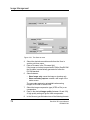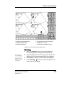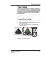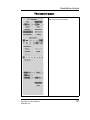
1
g
GE Medical Systems
Technical
Publications
EchoPAC PC
version 3.0.x
0470
User’s Manual
GEVU #: EP092537
GEVU Rev. 02
Operating Documentation
Copyright © 2003 By General Electric Co.
g
MANUAL STATUS
GE Medical Systems
20/05/03
© GE Medical Systems. All rights reserved. No part of this
manual may be reproduced, stored in a retrieval system, or
transmitted, in any form or by any means, electronic,
mechanical, photocopying, recording, or otherwise,
without the prior written permission of GE Medical
Systems.
COMPANY DATA
GE VINGMED ULTRASOUND A/S
EP092537-02
Strandpromenaden 45, N-3191 Horten, Norway
Tel.: (+47) 3302 1100 Fax: (+47) 3302 1350
Table of Contents
Table of Contents
Table of Contents
Introduction
Main functionality .......................................................................... 1
Indications for use......................................................................... 1
EchoPAC PC product range ......................................................... 1
Important ........................................................................................ 2
Manual contents ............................................................................ 3
Finding information ............................................................... 3
Conventions used in this manual.......................................... 3
Contact information ...................................................................... 5
Chapter 1
Getting started
Launching EchoPAC PC ............................................................... 8
To start EchoPAC PC: .......................................................... 8
EchoPAC PC overview.................................................................. 9
Chapter 2
Patient record management
Searching a Patient record ......................................................... 12
About dataflow .................................................................... 12
To find a patient record....................................................... 12
Advanced search ................................................................ 14
Sorting data ........................................................................ 15
Editing Referral Reasons, Comments and Diagnosis.............. 16
Text edition ......................................................................... 16
Editing demographic data .......................................................... 18
Creating a new Patient record.................................................... 20
Deleting archived information.................................................... 21
Deleting a patient record..................................................... 21
Deleting an examination ..................................................... 21
EchoPAC PC User's Manual
EP092537-02
iii
Table of Contents
Moving examinations................................................................... 22
Using removable media...............................................................24
Recommendation concerning CD-R handling .....................24
Formatting removable media............................................... 24
Ejecting removable media ................................................... 24
Export/Import patient records/examinations............................. 26
Exporting patient records/examinations .............................. 26
Importing patient records/examinations .............................. 32
Data Backup and restore............................................................. 36
Data backup for EchoPAC PC Software Only.....................36
Backup procedure ...............................................................37
Restore procedure...............................................................41
Chapter 3
Image Management
Introduction .................................................................................. 44
Image review................................................................................. 45
Review from the Image browser screen.............................. 45
Review from the Review screen..........................................49
Working with grouped images ............................................. 49
Image optimization....................................................................... 52
Image analysis screen overview ......................................... 52
Control panel overview........................................................54
Image controls adjustment .................................................. 64
Image optimization .............................................................. 66
Generated Anatomical M-Mode ..........................................69
Direct report......................................................................... 70
Saving stored images and cineloops to a standard format . 75
DICOM spooler .............................................................................80
Starting the DICOM spooler ................................................ 80
Chapter 4
Measurements and Analysis
Introduction .................................................................................. 84
Assign and Measure modality .................................................... 85
Starting the Assign and Measure modality.......................... 85
iv
EchoPAC PC User's Manual
EP092537-02
Table of Contents
Entering a study and performing measurements................ 87
Measure and Assign modality.................................................... 89
Starting the Measure and Assign modality ......................... 89
Performing measurements ................................................. 90
Post-measurement assignment labels................................ 99
Controlling the Measurement result table display ................. 101
Minimizing the Measurement result table ......................... 101
Moving the Measurement result table............................... 101
Chapter 5
Stress echo analysis
Introduction................................................................................ 104
Review of protocol studies....................................................... 105
Selecting images for analysis ........................................... 105
Loop synchronization........................................................ 107
Stress echo analysis ................................................................. 108
Starting analysis ............................................................... 108
Scoring.............................................................................. 109
Image optimization .................................................................... 111
To optimize images........................................................... 111
Zoom function ................................................................... 111
Quantitative TVI Stress echo analysis..................................... 112
Accessing QTVI Stress analysis tools .............................. 114
Vpeak measurement......................................................... 114
Tissue Tracking ................................................................ 117
Quantitative analysis......................................................... 118
References ....................................................................... 118
Editing/creating a template....................................................... 119
Template editor screen overview...................................... 119
Selecting a base template to edit...................................... 123
Chapter 6
Quantitative Analysis
Introduction................................................................................ 129
For TVI:............................................................................. 129
For Tissue Tracking: ......................................................... 129
EchoPAC PC User's Manual
EP092537-02
v
Table of Contents
For Strain rate: .................................................................. 129
For Strain:.......................................................................... 129
For Contrast: ..................................................................... 129
Accessing the Quantitative analysis package ........................ 130
Overview ..................................................................................... 131
The color cineloop window ................................................ 132
The Tissue cineloop window ............................................. 133
The analysis window ......................................................... 134
The control panel............................................................... 137
Generation of a trace ................................................................. 138
About the sample area ......................................................138
To generate a trace ........................................................... 138
Manual tracking of the sample area (dynamic anchored
sample area) ..................................................................... 139
Zooming in the Analysis window ....................................... 140
Deletion of a trace ...................................................................... 141
To delete all traces ............................................................ 141
To delete one specific trace .............................................. 141
Frame disabling.......................................................................... 141
Disabling frames from the frame marker ........................... 141
Disabling frames in the cineloop windows......................... 142
Re-enabling all frames ......................................................142
Optimizing sample area.............................................................143
Reshaping a sample area ................................................. 143
Labelling a sample area .................................................... 143
Optimizing the trace display ..................................................... 145
Optimizing the Y-axis ........................................................ 145
Trace smoothing................................................................ 146
Switching modes or traces ....................................................... 147
To switch mode ................................................................. 147
To switch trace .................................................................. 147
Curve fitting analysis................................................................. 148
Wash-in curve fitting analysis............................................ 150
Wash-out curve fitting analysis.......................................... 155
Anatomical M-Mode ................................................................... 157
Introduction........................................................................ 157
Using Anatomical M-Mode ................................................ 157
Optimizing Anatomical M-Mode ........................................159
vi
EchoPAC PC User's Manual
EP092537-02
Table of Contents
Chapter 7
Worksheet
Introduction................................................................................ 162
Overview..................................................................................... 163
Using Worksheet ....................................................................... 164
To scroll through pages .................................................... 164
To select the type of value................................................ 164
Excluding or including measurements .............................. 164
Manually changing a value ............................................... 164
Deleting measurement parameter .................................... 165
Chapter 8
Report
Introduction................................................................................ 168
Creating a report........................................................................ 169
Working with the report function ....................................... 169
To print a report ................................................................ 171
To save a report................................................................ 171
Retrieving an archived report............................................ 172
Report designer ......................................................................... 173
Accessing the Report designer......................................... 173
Report designer overview ................................................. 174
Designing a report template.............................................. 177
Saving the report template................................................ 182
Chapter 9
Program configuration
Introduction................................................................................ 184
Starting the Configuration package......................................... 186
To open the Configuration package.................................. 186
Overview..................................................................................... 187
Imaging....................................................................................... 188
The Global setup sheet..................................................... 188
Measure ...................................................................................... 190
Configuration of the Measurement menu ......................... 193
EchoPAC PC User's Manual
EP092537-02
vii
Table of Contents
Report.......................................................................................... 198
The Report templates sheet .............................................. 199
The diagnostic codes sheet...............................................201
The Comment texts sheet ................................................. 203
Connectivity................................................................................ 204
Dataflow ............................................................................ 205
Additional outputs.............................................................. 212
Tools..................................................................................215
Formats ............................................................................. 217
TCP/IP............................................................................... 221
System ........................................................................................ 222
The system settings .......................................................... 223
About........................................................................................... 227
Administration............................................................................ 228
Users ................................................................................. 229
Logon ................................................................................ 232
Appendix
Regulatory information.............................................................. 234
Standards used ................................................................. 234
Short-cuts ................................................................................... 236
Keyboard short-cuts .......................................................... 236
Mouse short-cuts............................................................... 238
Product description ................................................................... 240
TruAccess ......................................................................... 240
TruData acquisition ........................................................... 240
Patient record and Image management ............................ 240
TruAccess Image review ................................................... 241
Image post-processing ......................................................241
Image analysis .................................................................. 242
Report................................................................................ 242
EchoStress (option)........................................................... 242
EchoResearch (option)......................................................243
DICOM .............................................................................. 244
Hardware...........................................................................244
Software ............................................................................ 244
Safety ................................................................................ 245
Index
viii
EchoPAC PC User's Manual
EP092537-02
Introduction
Introduction
EchoPAC PC is a post processing program designed for
ultrasound image review, analysis and reporting. EchoPAC PC
allows post-processing of DICOM ultrasound images and raw
data images from GE ultrasound scanners.
Main functionality
EchoPAC PC offers the following functionality:
•
Read/display DICOM ultrasound and GE raw data images.
•
Ultrasound image optimization, as on a scanner.
•
Measurement and analysis
•
Advanced quantitative analysis, based on raw data such as
quantitative TVI, contrast and stress analysis (research
options)
•
Image storage
•
Patient record database
•
Report generator
Indications for use
EchoPAC PC is a workstation with post-processing and data
archiving capability compatible with the Vivid 7 ultrasound unit.
EchoPAC PC takes special advantage of the easy access to
ultrasound raw data provided from the Vivid 7, enabling full
image post-processing.
EchoPAC PC has also access to ultrasound data through
DICOM Media Interchange allowing import from removable
media and storage to removable media of DICOM images
(single or multiframe).
EchoPAC PC captures scan data from basic ultrasound
application such as adult and pediatric cardiac, stress echocardiography, transesophageal and intra-operative imaging.
EchoPAC PC product range
The EchoPAC PC product range consists of:
EchoPAC PC User's Manual
EP092537-02
1
Introduction
•
•
EchoPAC PC Workstation: a turnkey solution consisting
of hardware and software in a complete package.
EchoPAC PC Software Only: only the software to be
installed on any PC that fulfills minimum requirements.
The EchoPAC PC Workstation and The EchoPAC PC Software
Only have the same clinical functionality, except for the
following features that are not available in EchoPAC PC
Software Only:
•
No writing directly to CD-RW (Must be done by other
software packages).
•
The TCPIP settings cannot be configured within the
application (it must be done in Windows).
•
InSite/iLink is not available.
•
Removable media cannot be formatted within the
application.
•
Removable media cannot be ejected from within the
application.
•
The printer setup cannot be done from within the
application.
•
The Computer name cannot be set from within the
application.
Important
To ensure optimal performance, do NOT attempt to install any
software on the EchoPAC PC workstation.
CAUTION
CAUTION
2
The EchoPAC PC workstation must NOT be placed inside the
patient environment (refer to local regulations and EN 60601-1-1
(2000)).
EchoPAC PC User's Manual
EP092537-02
Introduction
1. Patient environment
2.5 m
1.5 m
1.5 m
Figure 1-1: The patient environment
Manual contents
The EchoPAC PC User manual is organized to quickly provide
the information needed for patient management and ultrasound
image post processing using the EchoPAC PC software.
Finding information
Data has been arranged in a format that will assist the user in
finding information easily and quickly.
Table of Contents: list the main topics and their location.
Headers and footers: displays the chapter name and page
number.
References: cross references are noted in the text.
Index: Extensive tool that provides easy reference to ideas,
topics, terms, titles, headings and cross references.
Conventions used in this manual
The following typographic conventions are used in the
indication of different types of information:
EchoPAC PC User's Manual
EP092537-02
3
Introduction
2-columns layout: the right column contains the main text, the
left column contains additional notes and warning texts.
Bold type: describes button name on the screen.
Italic type: describes program windows, screens and dialogue
boxes.
4
EchoPAC PC User's Manual
EP092537-02
Introduction
Contact information
If additional information or assistance is needed, please
contact the local distributor or the appropriate support resource
listed bellow:
Europe
GE Ultraschall KG
Tel: 0130 81 6370
Deutschland GmbH & Co.
Tel: (49)(0) 212-28-02-208
Beethovenstraße 239
Postfach 11 05 60
D-42655 Solingen
USA
GE Medical Systems
Tel: (1) 800-437-1171
Ultrasound Service Engineering
Fax: (1) 414-647-4090
4855 W. Electric Avenue
Milwaukee, WI 53219
On-line Applications Support
Tel: (1) 800-682-5327
or (262) 524-5698
Canada
GE Medical Systems
Tel: (1) 800-664-0732
Ultrasound Service Engineering
4855 W. Electric Avenue
Milwaukee, WI 53219
On-line Applications Support
Tel: (1) 800-682-5327
or (262) 524-5698
Latin and South America
GE Medical Systems
Tel: (1) 305-735-2304
Ultrasound Service Engineering
4855 W. Electric Avenue
Milwaukee, WI 53219
On-line Applications Support
Tel: (1) 800-682-5327
or (262) 524-5698
EchoPAC PC User's Manual
EP092537-02
5
Introduction
Brazil
GE Ultrasound
Tel: (55.11) 887-8099
Rua Tomas Carvalhal, 711
Fax: (55.11) 887-9948
Paraiso
Cep: 04006-002 - São Paulo, SP
6
EchoPAC PC User's Manual
EP092537-02
Getting started
Chapter 1
Getting started
Contents
• Launching EchoPAC PC .............................................................. ...... 8
• To start EchoPAC PC: ................................................................. 8
• EchoPAC PC overview ................................................................. ...... 9
EchoPAC PC User's Manual
EP092537-02
7
Getting started
Launching EchoPAC PC
To start EchoPAC PC:
1.
2.
Start the EchoPAC PC workstation.
The unit undergoes an initialization sequence and the
Operator login dialogue box is displayed (see Figure 1-1).
Enter the required information and press Log on.
The Search/Create patient window is displayed with the
default dataflow selected (see Figure 2-1, page 13).
1. Select the operator
2. Enter password
Figure 1-1: The Operator login windows
For user of EchoPAC PC Software Only:
CAUTION
8
It is possible in Windows to start several instances of EchoPAC
PC. I.e. the same application is launched more than once. It is
strongly recommended not to do this, as this will cause several
functions and features in EchoPAC PC not to work properly. Only
ONE instance of EchoPAC PC should be running.
EchoPAC PC User's Manual
EP092537-02
Getting started
EchoPAC PC overview
EchoPAC PC is build on eight different main screens that can
be entered by selecting the buttons in the top of the window
(see Figure 1-2).
7. Image Analysis:
• Image optimization
• Measurements
• Quantitative analysis
1. Selected screen
2. Archive
• Search patient
• Create patient
3. Patient:
• Patient info
• Examination list
• Medical info
8. Worksheet:
• Measurements listing
4. Image Browser:
• Displays a thumbnail overview of all images
stored for the current patient record
10. Config:
• EchoPAC PC configuration
9. Report:
• Summarizes data from examination
11. Help:
• Displays on-line user documentation
5. Review:
• Displays all images of the selected examination 12. Exit
6. Protocol:
• Review protocol based examinations
Figure 1-2: The EchoPAC PC navigation buttons
EchoPAC PC User's Manual
EP092537-02
9
Getting started
10
EchoPAC PC User's Manual
EP092537-02
Patient record management
Chapter 2
Patient record management
Contents
• Searching a Patient record .......................................................... .... 12
• To find a patient record .............................................................. 12
• Advanced search ....................................................................... 14
• Editing Referral Reasons, Comments and Diagnosis ............... .... 16
• Text edition ................................................................................. 16
• Inserting pre-defined text input ................................................... 16
• Editing demographic data ............................................................ .... 18
• Creating a new Patient record ..................................................... .... 20
• Deleting archived information ..................................................... .... 21
• Deleting a patient record ............................................................ 21
• Deleting an examination ............................................................. 21
• Moving examinations ................................................................... .... 22
• Using removable media ................................................................ .... 24
• Recommendation concerning CD-R handling ............................ 24
• Formatting removable media ..................................................... 24
• Ejecting removable media .......................................................... 24
• Export/Import patient records/examinations ............................. .... 26
• Exporting patient records/examinations ..................................... 26
• Importing patient records/examinations ..................................... 32
• Data Backup and restore .............................................................. .... 36
• Backup procedure ...................................................................... 37
• Restore procedure ..................................................................... 41
EchoPAC PC User's Manual
EP092537-02
11
Patient record management
Searching a Patient record
When the login procedure is completed, the Search/Create
patient window is displayed (see Figure 2-1).
About dataflow
Refer to page 204
for further information on connectivity
setup.
The connectivity on EchoPAC PC is based on the dataflow
concept. Each dataflow defines the transfer of patient
information from an input source to the unit, and from the unit to
an output source. Patient information can include demographic
data and images, as well as reports and Measurement and
Analysis data. A dataflow is a set of pre-configured services.
When beginning a search, the user selects a pre-configured
dataflow (see page 204 about connectivity) that will
automatically customize EchoPAC PC to work according to the
services associated to the dataflow and search in the archive
associated.
To find a patient record
EchoPAC PC can
be configured to
generate patient ID.
1.
The automatic
searching tool displaying matching
patient information
in the Patient list
can be turned off.
2.
12
3.
Type the patient Last Name, and/or ID.
When default configured, EchoPAC PC automatically
searches to see if the patient is already in the database.
The result of this search is displayed in the Patient list field.
If necessary, select another dataflow to search in other
databases.
In the Patient list field, Double-click the desired patient
record (or click once on the patient record and press Select
Patient)
Or
Press [+] in front of the actual patient record and select the
desired examination.
The Examination List window is displayed (see Figure 22).
EchoPAC PC User's Manual
EP092537-02
Patient record management
1. Press one of the headings to sort the list
accordingly.
4. Select the column heading border and drag to
adjust column width
2. Select new archive and other pre-defined
services
5. Expended Patient record displaying belonging
examinations
3. The system can be configured to display the
Advanced search tool as default (see page 217)
The Search/Create patient window may be slightly different depending on the Dataflow selected.
Figure 2-1: The Search/Create Patient window
EchoPAC PC User's Manual
EP092537-02
13
Patient record management
1. The information displayed in the Patient list is
configurable (see page 217).
2. Go to Search/Create Patient window (see page
13)
3. Insert pre-defined text in the Comment field
4. Select the column heading border and drag to
adjust column width
Figure 2-2: The Examination list window
Advanced search
The list of searching
filters may vary depending on the
dataflow selected
To restrain the search to a specific patient group, one or more
filters may be applied to the search. The table below shows the
filters applicable to a patient search:
Searching filter
Echolab
Diag. code
14
EchoPAC PC User's Manual
EP092537-02
Patient record management
Searching filter
Date of birth (time span)
Examination date (time span)
Current date
Images
Stress examinations
Report
Sorting data
The search result can be sorted according to the fields
displayed in the patient list, in ascending or descending order.
To sort data:
1.
2.
In the Patient list field, click on the header by which the sort
is to be performed (Figure 2-1, page 13).
The patient list is sorted in ascending order according to
the field selected.
Click once more on the header.
The patient list is sorted in descending order according to
the field selected.
EchoPAC PC User's Manual
EP092537-02
15
Patient record management
Editing Referral Reasons, Comments and
Diagnosis
The user can edit the actual text in the Examination List
window (see Figure 2-2) using the alphanumeric keyboard and
by inserting pre-defined text input.
Text edition
1.
Use the Arrow keys
to move text marker.
2.
Inserting pre-defined text input
1.
The Insert Text key
can be configured to
display an extended
writing field (see
page 217). In this
configuration, the
pre-defined text input function is
started from within
this new window.
In the Examination list window (Figure 2-2), click in the
required field to activate the text marker.
Using the alphanumeric keyboard, edit the information.
2.
3.
In the Examination list window, press Insert Text for the
actual field.
The Pre-defined texts list is displayed, showing the
abbreviation for the pre-defined text inputs (see Figure 23). The list has two levels, expand the list by selecting [+]
in front of a top level text input.
Select the pre-defined text input to insert.
The entire text is displayed as a preview (see Figure 2-3).
Double click on the selection.
The text is inserted in the main text at the cursor position.
Creating text input
1.
2.
The Code is the abbreviation shown in
the Pre-defined
texts list.
16
3.
4.
5.
In the Examination list window, press Insert Text for the
actual field.
The Pre-defined texts list is displayed (see Figure 2-3).
Press New text in the Pre-defined texts list to create a new
top level text input
or
select a top level text input and select New subtext to
create a sublevel text input.
The Text input window is displayed.
Type an abbreviation in the Code field.
Type the text input in the Full text window.
Press OK to confirm and exit.
The Pre-defined texts list is updated accordingly.
EchoPAC PC User's Manual
EP092537-02
Patient record management
1. Pre-defined text input list
4. Highlighted text input
2. Create top level text input
5. Expanded text input
3. Create sublevel text input
Figure 2-3: The pre-defined text input tool
EchoPAC PC User's Manual
EP092537-02
17
Patient record management
Editing demographic data
WARNING
If you modify the Patient ID, Last name, First name or Date of
birth on a patient in the archive, be aware that the contents of the
archived images for that patient is not updated. If the images are
still in the buffer and not yet archived, the image files are updated
if you modify any patient information, but not if the images are
archived. So if any of these images are later on exported to
DICOM media or DICOM server, they will still contain the original
patient information, as it was before you did the modification in
the archive. The system does not alter the contents of the image
files at all when doing DICOM export.
The demographic data for a selected patient record can be
edited from the Patient Information window.
Do NOT use '\' or '^' in patient information fields, as these
characters might cause problems with some DICOM devices.
CAUTION
1.
2.
18
Select a patient record (see page 12) and press Patient
Info in the Examination List window (see Figure 2-2).
The Patient information window is displayed (see Figure 24).
Edit the information using the keyboard or by choosing a
new selection from the drop-down menus.
Select the patient information category to enter application
specific patient information (Displayed when the button
More is depressed, see Figure 2-4.).
EchoPAC PC User's Manual
EP092537-02
Patient record management
1. The date format is configurable (see page 222). 3. The Address field is configurable (see page 217).
2. The window can be configured to display the
4. Select patient information category.
expanded patient info as default (see page 217).
Figure 2-4: The Patient information window
EchoPAC PC User's Manual
EP092537-02
19
Patient record management
Creating a new Patient record
EchoPAC PC can
be configured to
generate patient ID.
1.
2.
3.
In the Search/Create Patient window (see Figure 2-1),
enter patient Last Name, and/or ID.
press Create Patient.
The Patient Information window is displayed (see Figure 24).
Enter the necessary patient information.
Do NOT use '\' or '^' in patient information fields, as these
characters might cause problems with some DICOM devices.
CAUTION
20
EchoPAC PC User's Manual
EP092537-02
Patient record management
Deleting archived information
Deleting a patient record
1.
2.
3.
Select the patient record to delete (see page 12).
In the Search create Patient window (Figure 2-1, page 13),
press Delete.
A dialogue window is displayed asking for confirmation.
Press OK to delete the patient record.
Deleting an examination
1.
2.
Select the examination to delete (see page 12).
In the Examination list window (see Figure 2-2), select Del
Exam.
A dialogue window is displayed asking for confirmation.
Figure 2-5: Delete Examination prompt
EchoPAC PC User's Manual
EP092537-02
21
Patient record management
Moving examinations
Examinations can be moved from one patient record to
another.
1. In the Search/Create Patient window press [+] in front of
the patient record containing the examination(s) to move
(see Figure 2-1, page 13).
2. Select the examination to move.
To select several examinations, press and hold down CTRL
or SHIFT while selecting.
3. Press Move Exam.
The Move exam window is displayed.
Figure 2-6: The Move exam window
4.
5.
22
Search and select the target patient record.
Press Move Exam.
EchoPAC PC User's Manual
EP092537-02
Patient record management
A warning message is displayed asking the user to confirm
the action to perform (see Figure 2-7).
Figure 2-7: Moving examination prompt
6.
7.
Press OK.
An information window is displayed to confirm the
operation.
Press OK.
EchoPAC PC User's Manual
EP092537-02
23
Patient record management
Using removable media
The following removable media can be used for data storage:
•
5 1/4” Magneto Optical disk (1.3, 5.4 and 8.6 Gb)
•
3 1/2” Magneto Optical disk (1.3 Gb), option
•
Zip disk (250 Mb), option
•
CD-R (CD-RW is not supported)
The 9.1 Gb MOD is not supported on the EchoPAC PC.
CAUTION
Use only 24x or higher CD-R.
CAUTION
Recommendation concerning CD-R
handling
To avoid data loss, never touch the recordable surface of a CDR. Handle the disk only by the outer edge. Do not place it face
down on a hard surface. Fingerprints or scratches will make the
disk unusable. Before usage, verify that CD-R surface has no
visible scratches. If there are any scratches, do NOT use the
CD-R.
Avoid using CD-R to store patient data. The CD-R can be used for
storage of images for presentation purposes.
CAUTION
Formatting removable media
Removable media have to be formatted prior to use as
described in ’Tools’ on page 215.
Ejecting removable media
Do not eject the CD
using the button on
the CD drive.
24
1.
Press ALT+E to eject the disk.
The Eject device menu is displayed.
EchoPAC PC User's Manual
EP092537-02
Patient record management
Figure 2-8: The Eject device menu
2.
Select the relevant media.
The selected media is ejected.
EchoPAC PC User's Manual
EP092537-02
25
Patient record management
Export/Import patient records/examinations
Patient records/examinations from the local archive on one
system (EchoPAC PC or EchoPAC PC) can be exported to the
local archive on another system via a formatted Magneto
Optical (MO) disk or CD-R. Patient records/examinations from
the local archive can also be exported directly to a remote
archive (Echo server, DICOM server or EchoPAC PC
depending on the environment). In addition patient records/
examinations from a remote archive (Echo server or EchoPAC
PC depending on the environment) can be exported to a
removable media or to a DICOM server. Database information
(patient and report archives) can be exported with or without
images. No data is deleted from the source archive when
exporting data unless the command Delete selected
patient(s) after copy is checked in the Export patient window
(see Figure 2-10, page 28).
Similarly, patient records/examinations from the local archive
on one system can be imported to the local archive on another
system via a formatted MO disk or CD-R. Database information
can be imported with or without images. No data is deleted
from the source archive when importing data. In addition
patient records from a removable archive can be imported to a
remote archive (Echo server).
Exporting patient records/examinations
1.
2.
3.
4.
26
Insert a blank formatted (see page 215) removable media
in the drive.
Press Archive.
The Search/Create Patient window is displayed (see
Figure 2-1, page 13).
Select the source archive in the Dataflow field:
• LocalArchive-Int.HD: exports data from the local
archive.
• RemoteArch-RemoteHD: exports data from an Echo
server.
Press Export in the Search/Create Patient window.
The Export dialogue window is displayed.
EchoPAC PC User's Manual
EP092537-02
Patient record management
Figure 2-9: The Export Dialogue window
5.
Select one of the following destinations from the
Destination drop-down menu:
• Removable MOD Archive: exports raw and DICOM (if
present) data to a removable MOD.
• Pure DICOM MOD525/350 RW: export DICOM data
only to a removable MOD.
• Removable CD Archive: exports raw and DICOM (if
present) data to a CD-R.
• Pure DICOM CD-R: export DICOM data only to a CD-R.
• Remote Import/Export Archive: exports raw and
DICOM (if present) data to an Echo server (network) or
Vivid 7 (direct connect).
• Pure DICOM Storage: exports DICOM data only to a
DICOM server.
• Excel file: exports data to a spreadsheet. The excel file
is stored in the location defined in the Sublevel Tools in
the Configuration package (see page 215).
• HL7: exports examination results to the “Vivid HL7
Gateway”, which “feeds” the results to HIS through HL7
protocol. M&A and diagnosis-codes are stored as an
Excel file, reports are stored as CHM-files.
The file path to the shared volume on “Vivid HL7
Gateway” must be pre-configured in the Sublevel Tools
in the Configuration package (see page 215).
• DICOM Print: prints images to a DICOM printer via
DICOM spooler.
EchoPAC PC User's Manual
EP092537-02
27
Patient record management
6.
• MPEGvue: converts ultrasound images to MPEG format
readable from a regular computer and export them to a
CD.
Press OK.
The Export patient window is displayed (see Figure 2-10).
Figure 2-10: The Export patient window
7.
28
Search and Select the patient records to export in the
Patient list.
The following selection methods can be used:
• Press and hold down SHIFT while selecting patient
records/examinations to select several consecutive
items at a time.
• Press and hold down CTRL while selecting patient
records/examinations to select several discrete items.
• Press Select all in the Export patient window to export
all patient records.
EchoPAC PC User's Manual
EP092537-02
Patient record management
8.
9.
• Press Today to display today's examinations and select
the actual examinations.
• Fill in the Exam between field to display the patient
records done during a specific time period and select the
actual records.
• Fill in the Born between field to display the patient
records of patients born during a specific time period and
select the actual records.
Adjust the following settings as desired:
• Delete selected patient(s) after copy
• Copy images
• Copy only exams with on-line images: when checked
only selected examinations with accessible images will
be copied.
Press Copy.
If one or more patient examination is already present in the
destination archive the Export/Import conflict window is
displayed (see Figure 2-11). For each conflicting item,
select:
Keep: to keep the existing examination in the destination
archive.
Replace: to replace the existing examination with the
corresponding item in the source archive.
EchoPAC PC User's Manual
EP092537-02
29
Patient record management
Figure 2-11: The Export/Import conflict window
Do not eject the CD
using the button on
the CD drive
30
Press OK to resume export.
A progress indicator is displayed. When done a status
window is displayed showing the number of patient records
that have been successfully exported.
10. Press OK.
A check mark is displayed in the Copied field in the Export
patient window for each patient exported (see Figure 210).
A status message is displayed for each item exported.
Make sure that the operation was successful for each item
exported.
11. Press Done in the Export patient window to complete the
process.
12. Press ALT+E to eject the disk.
The Eject device menu is displayed.
EchoPAC PC User's Manual
EP092537-02
Patient record management
Figure 2-12: The Eject device menu
13. Select the relevant media.
The selected media is ejected.
EchoPAC PC User's Manual
EP092537-02
31
Patient record management
Importing patient records/examinations
1.
2.
3.
4.
Insert the removable media of the source archive in the
corresponding drive (MO drive, Zip drive or CD-ROM).
Press Archive.
The Search/Create Patient window is displayed (see
Figure 2-1, page 13).
Select destination archive in the Dataflow field:
• LocalArchive-Int.HD: imports data to the local archive.
• RemoteArch-RemoteHD: imports data to an Echo
server (network) or a Vivid 7 (direct connect).
Press Import in the Search/Create Patient window.
The Import dialogue window is displayed (see Figure 213).
Figure 2-13: The Import Dialogue window
5.
32
Select one of the following source archive from the Source
drop-down menu:
• Removable MOD Archive: imports raw and DICOM
data (if present) from a MOD.
• Pure DICOM MOD525/350 RW: imports DICOM data
only from a MOD.
• Removable CD Archive: imports raw and DICOM data
(if present) from a CD-R.
• Pure DICOM CD-R: imports DICOM data only from a
CD-R.
• Remote Import/Export Archive: imports raw and
DICOM (if present) data from an Echo server (network)
EchoPAC PC User's Manual
EP092537-02
Patient record management
6.
or EchoPAC PC (direct connect or network).
• Query Retrieve: imports data from a DICOM server.
Press OK.
The Import patient window is displayed (see Figure 2-14).
Figure 2-14: The Import patient window
7.
Search and Select the patient records to import in the
Patient list.
The following selection methods can be used:
• Press and hold down SHIFT while selecting patient
records/examinations to select several consecutive
items at a time.
• Press and hold down CTRL while selecting patient
records/examinations to select several discrete items.
• Press Select all in the Import patient window to export
all patient records.
• Press Today to display today's examinations and select
EchoPAC PC User's Manual
EP092537-02
33
Patient record management
8.
9.
34
the actual examinations.
• Fill out the Exam between field to display the patient
records done during a specific time period and select the
actual records.
• Fill out the Born between field to display the patient
records of patients born during a specific time period and
select the actual records.
Adjust the following settings as desired:
• Copy images
• Copy only exams with on-line images: when checked
only selected examinations with accessible images will
be copied.
Press Copy.
If one or more patient examination is already present in the
destination archive the Export/Import conflict window is
displayed (see Figure 2-11). For each conflicting item,
select:
Keep: to keep the existing examination in the destination
archive.
Replace: to replace the existing examination with the
corresponding item in the source archive.
EchoPAC PC User's Manual
EP092537-02
Patient record management
Figure 2-15: The Export/Import conflict window
Press OK to resume import.
A progress indicator is displayed. When done a status
window is displayed showing the number of patient records
that have been successfully imported.
10. Press OK.
A check mark is displayed in the Copied field in the Import
patient window for each item imported.
A status message is displayed for each item imported.
Make sure that the operation was successful for each item
imported.
11. Press Done in the Import patient window to complete the
process.
EchoPAC PC User's Manual
EP092537-02
35
Patient record management
Data Backup and restore
The Backup/Restore function enables the user to:
•
Copy/Restore the patient archive (patient database).
•
Move images and stored reports from the local harddrive to
MO disks.
•
Copy/Restore the system configuration.
To minimize accidental loss of data, perform backup of the
patient archive (patient data and reports) stored on the local
harddrive at least once a week.
WARNING
GE Medical Systems is not responsible for lost data if the
suggested backup procedures are not followed and will not aid
in the recovery of lost data.
There is no backup function for the images (no creation of a
safety copy). For long-term storage, images should be moved
to MO disks when performing backup as described below.
The backup of the patient archive on the harddrive and the
system configuration is done from the configuration
management package as described on page 37.
Data from Backup/Restore disks may be restored to the local
harddrive using the Restore procedure as described on page
41.
Only users with administration rights (see page 229) have
access to the backup function.
Data backup for EchoPAC PC Software
Only
Moving images
EchoPAC PC Software Only:
Moving images from the local harddrive to a removable media
can only be done using the procedure described in ’Backup
procedure’ on page 37. DO NOT attempt to move/copy images
in Windows Explorer as the image pointers in the patient
database will not be updated for the images in the new
location. If you copy images in Windows Explorer and delete
36
EchoPAC PC User's Manual
EP092537-02
Patient record management
the original images you will not be able to retrieve the images
again.
Backup of patient archive
EchoPAC PC Software Only:
Backup of the patient archive should be done using the
procedure described in ’Backup procedure’ on page 37.
Backup procedure
CAUTION
When formatting
the MO disk, give it
a logical name and
make sure to physically label the disk
with the mention
“Backup”. A labelling convention
should be followed
so that each MO
disk gets a unique
label.
Use a blank dedicated MO disk when doing a backup. This MO
disk should only be used for backup/restore purpose (Do not use
this MO disk when doing Export or Save as.). The backup
procedure will OVERWRITE the existing data on the MO disk.
If moving images, make sure to have enough formatted MO
disks before disponible.
1. Insert a formatted (see page 215) MO disk in the MO drive.
2. Press Config.
The Log In window is displayed asking for operator ID and
password.
3. Select the user with administration rights and enter the
password.
4. Select Log on.
The Setup dialogue window is displayed.
5. Select the Admin setup category. The Backup sheet is
displayed (Figure 2-16).
6. Select:
• Patient archive to backup patient records.
• System setting to copy system settings and user
presets. The system configuration backup can be used
to configure several EchoPAC PC units with identical
presets, providing the units have the same software
version.
• Move oldest images to move images and reports from
the local harddrive onto MO disks. Adjust the time span
next to Older than to move images and reports older
than that setting.
7. Select the MO disk as destination.
8. Press Backup Now.
EchoPAC PC User's Manual
EP092537-02
37
Patient record management
• The system is checking that the MO disk is inserted. If
not, a dialogue window is displayed prompting the user
to insert a MO disk. Press OK to resume backup.
• The system is checking that the MO disk is formatted. If
not, a dialogue window is displayed prompting the user
to format the disk.
• The system is checking the available space on MO disk
for the patient archive. If there is not sufficient free space
a dialogue window is displayed. Press OK, the media is
ejected and insert a new formatted MO disk.
A progress dialogue is displayed showing the current
operation being performed.
If the amount of data exceeds the capacity of the MO disk
the user is prompted to insert a new (formatted) MO disk.
At the end of the process a status for each item is
displayed in the Result column.
If errors occur during backup, a list of the patient records/
examinations that could not be backed up is displayed.
38
EchoPAC PC User's Manual
EP092537-02
Patient record management
1. Select the item to backup
4. Start backup
2. Select and adjust the Move images function
5. Adjust the backup reminder
3. Select the MO disk as backup destination
Figure 2-16: The Backup sheet
Set up backup reminder
1.
In the Backup sheet, select the time interval (or none) for
the backup reminder next to Backup interval.
When the backup reminder time expires a reminder is
displayed when starting the system to prompt the user to
take a backup.
EchoPAC PC User's Manual
EP092537-02
39
Patient record management
Figure 2-17: The Backup reminder prompt
40
EchoPAC PC User's Manual
EP092537-02
Patient record management
Restore procedure
1.
Insert the Backup/Restore MO disk in the MO drive.
The Restore procedure will OVERWRITE the existing database
on the local harddrive. Make sure to insert the right MO disk.
CAUTION
2.
3.
4.
5.
6.
7.
8.
9.
Press Config on the alphanumeric keyboard.
The Log In window is displayed asking for operator ID and
password.
Select the user with administration rights and enter the
password.
Select Log on.
The Setup dialogue window is displayed.
Select the Admin setup category.
Select the Restore sheet in the Admin setup category
(Figure 2-18).
Select:
• Patient archive to restore patient records and reports.
• System setting to restore/copy system settings and
user presets.
Make sure that the Backup/Restore MO disk is inserted in
the MO drive and selected as the source.
Press Restore Now.
The process status for each item is displayed in the Result
column.
EchoPAC PC User's Manual
EP092537-02
41
Patient record management
1. Select the item to restore
3. Start restoring data
2. Select the Backup/Restore disk
4. Reset the system setting to factory default.
Figure 2-18: The Restore setup sheet
42
EchoPAC PC User's Manual
EP092537-02
Image Management
Chapter 3
Image Management
Contents
• Introduction ................................................................................... .... 44
• Image review ................................................................................. .... 45
• Review from the Image browser screen ..................................... 45
• Review from the Review screen ................................................. 49
• Working with grouped images .................................................... 49
• Image optimization ....................................................................... .... 52
• Image analysis screen overview ................................................ 52
• Control panel overview ............................................................... 54
• Image controls adjustment ......................................................... 64
• Image optimization ..................................................................... 66
• Generated Anatomical M-Mode ................................................. 69
• Direct report ............................................................................... 70
• Saving stored images and cineloops to a standard format ........ 75
• DICOM spooler .............................................................................. .... 80
• Starting the DICOM spooler ....................................................... 80
EchoPAC PC User's Manual
EP092537-02
43
Image Management
Introduction
EchoPAC PC allows post-processing of DICOM ultrasound
images and raw data images from GE ultrasound scanners.
The user selects the images to analyze from the Image
browser screen (displays a thumbnail overview of all stored
images sorted by examination for the current patient) or from
the Review screen (displays all images for the current
examination) or from the Protocol screen for examinations
based on protocol studies.
The main features of the EchoPAC PC image analysis package
are:
•
Image optimization: adjusts image settings such as
Compress, Reject, Tissue priority, zooming, image rotation,
cineloop replay adjustment...etc.
•
Measurement and Analysis: performs either single
measurement with post-assignment or protocol based preassigned measurements (see Chapter 4, ’Measurements
and Analysis’ on page 83).
•
Review and analyze protocol studies such as Stress
echo examinations including quantitative stress echo
analysis (see Chapter 5, ’Stress echo analysis’ on page
103).
•
Quantitative analysis of Tissue Velocity, Tissue Tracking
and contrast imaging data (see Chapter 6, ’Quantitative
Analysis’ on page 127).
44
EchoPAC PC User's Manual
EP092537-02
Image Management
Image review
Images can be reviewed from the Image browser screen or
from the Images review screen.
•
The Image browser screen displays a thumbnail overview
of all stored images sorted by examination session for the
current patient. The user can preview and group images
from one or more examinations for the current selected
patient to enable comparison analysis.
•
The Image review screen displays all images for the current
examination.
Review from the Image browser screen
The procedure described below enables the analysis of images
belonging to different examinations for a selected patient
record. If images are stored on multiple removable media, they
have to be restored to the local hard drive prior to review as
described below.
1. In the Examination list window, press Image list or the
Image browser menu button.
The Image browser screen is displayed (see Figure 3-3)
showing thumbnails of stored images for the current
patient sorted by examination sessions.
If the images are stored on a removable media that is not
mounted, the image thumbnail is replaced by a symbol.
2. Move the Mouse cursor over a thumbnail to display a
preview of the image.
3. Select the images to review or press Analyze to review all
images.
• If all images are available the images are displayed for
review.
• If some of the images are not available locally the
Restore images window is displayed.
EchoPAC PC User's Manual
EP092537-02
45
Image Management
Figure 3-1: The Restore images window
4.
5.
46
Select between:
• Restore only the selected images: only selected
images that are not available locally are restored.
• Restore all images of the selected exam: all images
that are not available locally in the exams where an
image was selected are restored.
• Restore current patient: restores all images in all
examinations.
Press OK.
The Insert media window is displayed.
EchoPAC PC User's Manual
EP092537-02
Image Management
Figure 3-2: The Insert media window
6.
7.
Insert the required media.
Select between:
• OK: the images on the mounted media are restored on
the local hard drive. If not all the required images are on
the inserted media, the user is prompted to insert
another media until all required images are restored on
the hard drive.
• Skip media: the images stored on the media required
are not restored. If not all the required images are on the
inserted media, the user is prompted to insert another
media until all required images are restored on the hard
drive.
• Cancel: no images are restored.
The selected images are displayed for review.
EchoPAC PC User's Manual
EP092537-02
47
Image Management
1. Examination
2. Examination date
and archive location
3. Selected image
4. Preview of selected
image
5. Missing images
Figure 3-3: The Image browser screen
48
EchoPAC PC User's Manual
EP092537-02
Image Management
Review from the Review screen
1.
In the Examination list window, select an examination and
press the Review menu button.
The Review screen is displayed showing all images for the
current examination (see Figure 3-4).
1. Page number
3. Selection tools
2. Selected image (bold frame)
Figure 3-4: The Review screen
Working with grouped images
Grouping images
1.
2.
From the Image browser screen, click once on each image
thumbnail of the images to group.
The selected image thumbnails are displayed with a
highlighted frame.
Press New Group.
EchoPAC PC User's Manual
EP092537-02
49
Image Management
A dialogue box is displayed prompting the user to name
the group (see Figure 3-5).
1. Images belonging to
the selected group
2. Enter a name for the
group
Figure 3-5: Creating a group of images in the Image browser screen
3.
4.
5.
6.
50
Type a name for the group.
Press OK.
The group list on the right side of the screen is updated.
To select the group, press on the group in the Group list.
Both the group name and the belonging image thumbnails
are highlighted (see Figure 3-6).
Select Analyze to start analysis (see Chapter 4,
’Measurements and Analysis’ on page 83).
EchoPAC PC User's Manual
EP092537-02
Image Management
1. Images belonging to
the selected group
2. Selected group
Figure 3-6: Selecting a group of images in the Image browser screen
To update an image group
1.
2.
3.
Select the group to update from the Group list.
Both the group name and the belonging image thumbnails
are highlighted.
• To add images to the group: select the image
thumbnails.
• To remove images from the group: deselect the image
thumbnails.
Press Update Group.
To delete an image group
1.
2.
Select the group to delete from the Group list.
Press Delete Group.
The Group list is updated accordingly.
EchoPAC PC User's Manual
EP092537-02
51
Image Management
Image optimization
Image optimization is performed in the Image analysis screen
after selection of the image of interest in the Image browser
screen, the Review screen or the Protocol screen.
From the Image browser screen, the user can analyze images
from different examination sessions for the selected patient.
From the Review screen the user analyzes images from the
currently selected examination.
From the Protocol screen the user can analyze images from a
stress echo examination.
Image analysis screen overview
The Image analysis screen consists of:
•
a Display window showing up to 12 ultrasound images
(single frame and cineloop), see Figure 3-7.
•
a Control panel for image optimization and analysis. The
control panel is mode-dependent (see Figure 3-8 through
Figure 3-12).
52
EchoPAC PC User's Manual
EP092537-02
Image Management
1. Display window
4. Selected image (Highlighted frame)
2. Control panel
3. Status bar
Figure 3-7: The Analysis screen
EchoPAC PC User's Manual
EP092537-02
53
Image Management
Control panel overview
The control panel can be displayed in three states:
•
Minimized: displays only a few controls. This setting
enables maximum image display area.
•
Basic: displays a selection of mode specific controls.
•
Advanced: displays all the mode specific controls.
Control panel display
Switch between minimized and basic/advanced display
1. Press the button on the upper left corner of the control
panel.
Switch between basic and advanced display
1. When the advanced control panel is displayed, press
<< Basic
When the basic control panel is displayed, press
Advanced >>.
54
EchoPAC PC User's Manual
EP092537-02
Image Management
Advanced
Basic
Minimized
Figure 3-8: The 2D control panel
EchoPAC PC User's Manual
EP092537-02
55
Image Management
Advanced
Basic
Minimized
Figure 3-9: The M-Mode control panel
56
EchoPAC PC User's Manual
EP092537-02
Image Management
Advanced
Basic
Minimized
Figure 3-10: The 2D Color control panel
EchoPAC PC User's Manual
EP092537-02
57
Image Management
Advanced
Basic
Minimized
Figure 3-11: The M-Mode Color control panel
58
EchoPAC PC User's Manual
EP092537-02
Image Management
Advanced
Basic
Minimized
Figure 3-12: The Doppler Spectrum control panel
EchoPAC PC User's Manual
EP092537-02
59
Image Management
Control
Description
Run/Stop Cineloop (All modes):
Starts and stops the cineloop (shortcut:
ALT + R or SPACE BAR).
When running, use Speed/Frame to adjust the
cine speed.
When stopped, use Speed/Frame to scroll
through the cineloop.
2D Gain (All modes):
Tissue gain
Gain (All modes but 2D):
Gain for the active mode.
Caliper (All modes):
Activates measurement tool (unassigned
measurement).
Measure (All modes):
Activates the Measurement & Analysis (M&A)
calculation program (protocol based preassigned measurements).
Quantitative Analysis (2D, 2D Color):
Starts the Quantitative analysis program for
TVI and contrast applications (see page 127).
Direct report (All modes):
Displays the Direct report where the user can
enter comments, diagnosis and Ref. reason
information while doing image analysis.
The Direct report displays also an overview of
the measurements performed.
Store (All modes):
Stores the currently active image to disk.
Alt. Store 1 and 2 (All modes):
Stores the image to an alternative media. This
function is configurable.
Basic/Advanced:
Displays the basic or advanced control panel.
60
EchoPAC PC User's Manual
EP092537-02
Image Management
Control
Description
Active mode (Color, M-Mode, Doppler):
In combined mode, switches between modes
to activate the mode specific controls.
Mode selection (All modes):
In combined mode, select the mode to display.
Annotation:
Enables the insertion/deletion of body marks,
arrows and text in the selected image.
Physio:
Enables to display/hide and adjust the
physiological traces.
Compare (All modes):
Displays a copy of the selected cineloop.
Enables frame by frame comparison of the
selected cineloop (independent scrolling).
Image size (Doppler, M-Mode):
Toggles the display priority of 2D Mode or
Doppler/M-Mode and top/bottom (1) or side by
side display with 2D priority (2) or time-motion
priority (3) when working in combined mode.
Cineloop:
Displays the cineloop controls (see (page 66)).
Apply to All (All modes):
Applies changes on all opened images.
Works for the following controls: Up/Down,
Left/Right, Invert, Variance, Persistence,
Tissue priority, Gain, Compress, Reject,
Baseline, Mode selection and Color Map.
Reset (All modes):
Restore all controls to original setting.
EchoPAC PC User's Manual
EP092537-02
61
Image Management
Control
Description
1 to 12:
Select the number of images to display.
Up/down (2D, 2D Color, M-Mode):
Flips the image 180 degrees.
Map (All modes):
Selects mode specific color map from the popup menu.
Variance (2D Color):
Controls the amount of variance data added to
a color display. Variance enables computeraided detection of turbulent flow (e.g. jets or
regurgitation).
Left/Right (2D, 2D Color):
Creates a mirror image of the original image.
The left/right reference marker V moves to the
other side of the image.
Invert (2D Color, Doppler):
Enables the color scheme assigned to positive
and negative velocities to be inverted.
Simultaneous (2D Color, TVI modes):
Enables simultaneous display of 2D image and
color image.
Compress (All modes):
Controls the amount of contrast.
DDP (2D, 2D Color):
Performs temporal processing which reduces
random noise without affecting the motion of
significant tissue structures.
Reject (All modes):
Discards low levels echoes when increased.
Zoom (All modes):
Magnifies the image display in both frozen and
live (see page 66).
Horizontal sweep (M-Mode, Doppler):
Controls the time scale in the time-motion
display.
62
EchoPAC PC User's Manual
EP092537-02
Image Management
Control
Description
Tissue priority (2D Color):
Emphasize either the color of the color mode
or the greyscale tissue detail of the 2D image.
Angle Correct. (Doppler):
Enables stepwise angle correction (by 2
degrees) of the Doppler velocity scale.
Transparency (All TVI modes):
Controls the degree of transparency of the
color display.
Threshold (All TVI modes):
Controls the level of greyscale intensity that is
used as a threshold for color.
TT Start (Tissue Tracking), Strain Start
(Strain):
The time after ECG R-peak when the mode
specific calculation starts.
TT End (Tissue Tracking), Strain End
(Strain):
The time after Track or Strain End when the
mode specific calculation should end.
TT scale (Tissue Tracking):
Controls the color cut-off value of max
displacement displayed.
SI length (Strain rate, Strain):
Determines the Strain/Strain rate sample
volume size.
SRI reject (Strain rate), SI reject
Adjusts the cut-off level of the low tissue
velocity to be discarded. Rejected values are
uncolored (Strain) or green (Strain rate).
Cine compound (All TVI modes):
Calculates and displays cineloops generated
from a temporal averaging of multiple
consecutive heart cycles.
EchoPAC PC User's Manual
EP092537-02
63
Image Management
Control
Description
SI scale (Strain), SRI scale:
Define the scale for the color coding for strain
or strain rate.
TSI start (Tissue Synchronization Imaging):
The time from the onset of QRS when TSI
starts, indicated by a red marker on the ECG.
The default value is set to approximate the
time for start ejection and by the value on the
left side of the color bar.
TSI end:
The time after TSI start when TSI ends,
indicated by a red marker on the ECG. The
default value is set to approximate the aortic
valve closure and by the value on the right side
of the color bar.
TSI algorithms (Tissue Synchronization
Imaging):
Enables the display of the following TSI
features:
• Time to peak positive velocity: color-codes at
what time the tissue velocity reaches its peak
positive value.
• Time to onset of positive velocity: colorcodes at what time the velocity increases
above a given TSI Threshold (default 0 cm/
s).
• Time to peak negative Strain rate: colorcodes at what time the tissue strain rate
reaches its peak negative value.
TSI Threshold (Tissue Synchronization
Imaging):
Controls the minimum value to detect.
Image controls adjustment
Controls with multiple settings can be adjusted in two ways as
shown in (Figure 3-13).
64
EchoPAC PC User's Manual
EP092537-02
Image Management
1. Decrease stepwise
2. Increase stepwise
3. Select setting on the
scale
Figure 3-13: Image control adjustment
EchoPAC PC User's Manual
EP092537-02
65
Image Management
Image optimization
1.
2.
3.
4.
5.
6.
Select the image of interest.
The control panel displays the mode specific controls.
If necessary display the advanced control panel (see page
54).
If applicable, deselect Run Cineloop to freeze the image
and scroll through the cineloop using the Speed/Frame
control or by dragging the frame marker on the ECG to
display the desired image.
In dual modes, press Image size until the desired display is
shown (see page 61).
Press Active mode to toggle between modes. The control
panel is updated accordingly.
Adjust the mode specific image controls to optimize the
display.
Press Store to save the changes.
Zoom function
1.
2.
3.
Select inside the Zoom scale or press the Zoom increase
button.
OR
Press ARROW UP.
A portion of the selected image is magnified and a
situation picture is displayed showing the outlined zoom
region.
Press and hold down the Left mouse button while moving
the mouse upward to increase magnification or downward
to decrease magnification.
OR
Press ARROW UP to magnify or ARROW DOWN to decrease
magnification.
Press and hold down SHIFT and the Left mouse button
while moving the mouse to move the zoomed area.
OR
Press SHIFT and RIGHT ARROW or LEFT ARROW.
Optimizing cineloop
The cineloop boundaries can be adjusted by dragging the left
and right markers on the ECG or by using the cineloop controls
as described below.
66
EchoPAC PC User's Manual
EP092537-02
Image Management
Cineloop overview
1. ECG
2. Loop display
3. Left marker: drag to
move.
4. Current frame: in
freeze, drag to select
frame or select frame
on ECG.
5. Right marker: drag to
move.
6. Cine speed (replay)
Figure 3-14: The cineloop display and controls
To run/stop a cineloop
1. Press Run/Stop or ALT + R or SPACE BAR.
To jump directly to
the first or to the
last heart beat press
the First cycle or
Last cycle button.
Cineloop adjustment
1. Select a cineloop.
2. If necessary, press Run/Stop to freeze the cineloop.
3. Press Cineloop.
The cineloop controls are displayed on the control panel
(see Figure 3-14).
4. Using the Cycle select control, move from heart beat to
heart beat to select the heart cycle of interest.
5. Using the Num cycles, adjust the number of heart cycle to
incorporate to the cineloop.
6. Using the Left marker and Right right controls, trim or
expand the cineloop boundaries.
7. Check Sync to synchronize all the cineloop.
EchoPAC PC User's Manual
EP092537-02
67
Image Management
8.
68
Press Done to return to the Image Analysis screen.
EchoPAC PC User's Manual
EP092537-02
Image Management
Generated Anatomical M-Mode
Anatomical M-Mode (AMM) displays can be generated from
raw data 2D, 2D Color and TVI images.
To generate Anatomical M-Mode images
1.
2.
3.
5
In the Image analysis screen, select a 2D, 2D Color or TVI
image.
Select MM or AMM.
The Display window is updated with an M-Mode image.
The 2D sector displays a time motion cursor for the AMM.
Adjust the AMM cursor position and angle as shown in
Figure 3-15.
All other controls are similar to conventional M-Mode (see
page 54 and followings).
v
5
10
v
10
15
15
1. AMM cursor angle adjustment
2. AMM cursor position adjustment
Figure 3-15: Adjustment of the AMM cursor
EchoPAC PC User's Manual
EP092537-02
69
Image Management
Direct report
Direct report enables the user to write comments during image
analysis that will be part of the final report.
Direct report provides also an overview over the measurements
completed.
Creating comments
1.
2.
3.
70
Press Direct report (see Figure 3-16).
Select the comment type.
Type your comments in the Text field.
EchoPAC PC User's Manual
EP092537-02
Image Management
1. Open Direct report
2. Select the type of
information
3. Create/insert predefined text
4. Text field
5. List of
measurements
completed
6. Exits the Direct
report
Figure 3-16: The Direct report
Inserting pre-defined text input
1. Select the insertion point in the Text field.
2. Select Insert text.
EchoPAC PC User's Manual
EP092537-02
71
Image Management
The Insert text window is displayed (see Figure 3-17).
Figure 3-17: The Insert text window
3.
The pre-defined text list is organized in a three level
hierarchy. Selecting one item in column one (Item)
displays a specific pre-defined text list in column two
(Pathology) related to the item selected. Likewise
selecting a pathology term in column two displays a
specific pre-defined text list in column three (Descriptor)
related to the pathology selected.
Navigate through the pre-defined text list by selecting items
in the columns and double-click on the desired pre-defined
text to be inserted. If a descriptor is selected, both the
descriptor and the pathology texts are inserted.
Press More>> to display the full text for the selected term.
Creating pre-defined text input
Creating a new Item (first level)
1. Select the first level.
2. Press New.
The Enter new text window is displayed.
72
EchoPAC PC User's Manual
EP092537-02
Image Management
Figure 3-18: The Enter new text window
3.
4.
Enter a title for the item in the Text field.
Enter the pre-defined text in the Full text field.
Press OK.
New Pathology text
1. Select the item in the first column.
2. Select the second column.
3. Press New.
The Enter new text window is displayed (Figure 3-18).
4. Enter a title for the Pathology in the Text field.
Enter the pre-defined text in the Full text field.
5. Press OK.
New Descriptor text
1. Select the item in the first column.
2. Select the Pathology term in the second column.
3. Select the third column.
4. Press New.
The Enter new text window is displayed (Figure 3-18).
5. Enter a title for the Descriptor in the Text field.
Enter the pre-defined text in the Full text field.
6. Press OK.
EchoPAC PC User's Manual
EP092537-02
73
Image Management
Editing a pre-defined text input
1.
2.
3.
Select the term to edit in one of the columns.
Press Edit.
The Edit text window is displayed.
Figure 3-19: The Edit text window
4.
5.
Edit the text in both the Text and Full text fields.
Press OK.
Deleting a pre-defined text input
1.
2.
3.
4.
74
Select the term to delete in one of the columns.
Press Delete.
A Confirmation window is displayed.
Press Yes.
The selected text input is deleted including the belonging
text inputs.
EchoPAC PC User's Manual
EP092537-02
Image Management
Saving stored images and cineloops to
a standard format
Stored images and cineloops can be saved to a formatted (see
page 215) MOD or a CD-R in the following standard formats:
•
Still images: JPEG, DICOM and RawDICOM (Raw data +
DICOM)
•
Cineloops: AVI, DICOM and RawDICOM (Raw data +
DICOM)
Images can also be stored as MPEG format on a CD-R using
the Export function as described on page 77.
Procedure:
1.
2.
In the Image analysis screen. select the required image or
loop.
Press the Right mouse button.
The System menu is displayed.
Figure 3-20: The System menu
3.
Select Save as.
The Save as menu is displayed.
EchoPAC PC User's Manual
EP092537-02
75
Image Management
Figure 3-21: The Save as menu
4.
5.
6.
7.
8.
9.
76
Select the desired removable media from the Save in
archive pull-down menu.
Enter a file name in the File name field.
If the image or cineloop is saved as DICOM or RawDICOM
the file name is automatically generated to follow the
DICOM standard.
Select between:
• Store image only: saves the image or cineloop only.
• Store secondary capture: creates a still image of the
entire screen.
The secondary capture is not available when saving
images as DICOM or RawDICOM.
Select the image compression type (JPEG or RIe) or no
compression.
Enter in the desired Image quality (between 10 and 100).
A high quality setting will give a lower compression.
In the Save as type field select one of the following formats:
EchoPAC PC User's Manual
EP092537-02
Image Management
• RawDICOM: saves the still image or cineloop in both GE
raw format and DICOM format.
• DICOM: saves the still image or cineloop in pure DICOM
format.
• JPEG: saves a still image in JPEG format.
• AVI: saves the cineloop in AVI format.
10. Press Save.
A file is saved in the selected archive.
MPEGvue
MPEGvue enables the user to convert ultrasound images to
MPEG format and create a CD that is readable from a regular
computer.
Creating a MPEGvue CD
1.
2.
EchoPAC PC Workstation
Insert a formatted CD-R in the drive.
Export the actual patient records as described on page 26.
Make sure to select MPEGvue as the export destination.
EchoPAC PC Software Only:
When export patient records to MPEGvue on EchoPAC PC
Software Only, the data is stored to a folder called MPEGvue
on the local harddisk. This folder is located in Archive/Export.
To make a MPEGvue CD, the entire contents of the MPEGvue
folder must be written to the CD. After creating the CD, the
MPEGvue folder should be deleted, otherwise its content will
be added to the next MPEGvue export.
Reading MPEGvue CD
MPEGvue CD can be read form any computer with Windows
98/2000/XP, provided that DirectX 8.1 or later and Windows
Media Player 7.1 or later are installed.
1. Insert the MPEGvue CD in the computer CD drive.
The MPEGvue Patient list is displayed.
EchoPAC PC User's Manual
EP092537-02
77
Image Management
1. Select the examination date.
Figure 3-22: The MPEGvue Patient list
2.
78
Select the desired examination date to display the
belonging images.
The MPEGvue screen is displayed (Figure 3-23).
EchoPAC PC User's Manual
EP092537-02
Image Management
1. Clipboard: select the image to display
6. Scrolling tool when in Freeze
2. Selected image
7. Display previous image
3. Single frame image
8. Display next image
4. Cineloop
9. Display the MPEGvue patient list
5. Freeze/run cineloop
Figure 3-23: The MPEGvue screen
EchoPAC PC User's Manual
EP092537-02
79
Image Management
DICOM spooler
DICOM spooler displays the current DICOM output jobs. The
jobs may be Storage, Print, Modality Performed Procedure
Step or Storage Commitment. The DICOM spooler is used for
checking the current job's status when a job is saved or when
the total spooler status on the right of the Archive windows
displays an error.
From the DICOM spooler the user can also:
•
Delete non-active jobs
•
Resend a job that has failed or is in hold
•
Send a job that has failed or is in hold, to a new destination.
The job's status displayed in the DICOM spooler window can
be:
•
Pending: the job is complete, waiting to be active.
•
In hold: the job is incomplete, waiting for more images.
•
In progress: the job is connected to the destination device
but is waiting for more images (Direct store function).
•
Active: the job is complete but one or more images failed
to transmit to the destination device.
•
Failed: the job is complete but failed to connect to the
destination device.
•
Done: the job is saved to the destination device. The jobs
that are done are removed from the spooler after a while.
Starting the DICOM spooler
1.
Press and hold down the ALT key and press S.
The DICOM spooler window is displayed (see Figure 324).
The DICOM spooler window is automatically updated every
minute. Press Refresh to update the information displayed at
any time.
80
EchoPAC PC User's Manual
EP092537-02
Image Management
Figure 3-24: The DICOM job spooler window
Deleting a job
Only non-active
jobs can be deleted.
1.
2.
Select the job to delete in the DICOM job spooler window.
Press Delete.
Resending a job
Only jobs that
failed or are in hold
can resent.
1.
2.
3.
Select the job to resend in the DICOM job spooler window.
Press Resend.
Press SELECT.
Sending a job to a new destination
Only jobs that
failed or are in hold
can be sent to a new
destination.
1.
2.
3.
4.
Select the job to send in the DICOM job spooler window.
Press Send to....
A dialogue window is displayed.
Select the new destination from the Destination popup
menu.
Press Send.
EchoPAC PC User's Manual
EP092537-02
81
Image Management
82
EchoPAC PC User's Manual
EP092537-02
Measurements and Analysis
Chapter 4
Measurements and Analysis
Contents:
• Introduction ................................................................................... .... 84
• Assign and Measure modality ..................................................... .... 85
• Starting the Assign and Measure modality ................................. 85
• Entering a study and performing measurements ....................... 87
• Measure and Assign modality ..................................................... .... 89
• Starting the Measure and Assign modality ................................. 89
• Performing measurements ......................................................... 90
• Post-measurement assignment labels ....................................... 99
• Controlling the Measurement result table display ..................... .. 101
• Minimizing the Measurement result table ................................. 101
• Moving the Measurement result table ...................................... 101
EchoPAC PC User's Manual
EP092537-02
83
Measurements and Analysis
Introduction
A study is a set of
related measurements, or measurements that are
logically grouped
together. The measurements in a
study are sometimes used in a formula to calculate
new parameters
(e.g. biplane volume
with EF, SV and
CO).
EchoPAC PC provides functionality for two measurement
conventions:
•
Assign and Measure (Measure Protocols): the user
selects a study consisting in a set of pre-labeled
measurements related to the active scanning mode and
clinical application. The user is prompted through the
measurements in the order of the measurements labels.
This convention is started from the Measure button. A set
of tools is implemented to make the measurement process
as fast and easy as possible for the user:
• The user is guided through the study: an auto-sequence
functionality automatically selects the next
measurement in a study.
• The selected measurement is highlighted in the
Measurement menu.
• The performed measurement is indicated in the
Measurement menu.
The studies and their parameters are user-configurable. The
user can create its own studies containing the relevant
measurements only.
•
Measure and Assign (Free style): the user performs a
measurement and assigns a label. This convention is
started either from the buttons Measure or Caliper.
Only assigned measurements will be saved. Measurements
without assignment will be lost when scanning is resumed.
CAUTION
84
EchoPAC PC User's Manual
EP092537-02
Measurements and Analysis
Assign and Measure modality
In this measurement modality, the user selects a study
consisting in a set of related pre-labelled measurements.
Starting the Assign and Measure
modality
1.
In the Image analysis screen, click on Measure.
The Measurement Menu is displayed over the control
panel (see example Figure 4-1).
The cursor is in the display window, ready for starting
measurement.
EchoPAC PC User's Manual
EP092537-02
85
Measurements and Analysis
1. Active application
2. Study
3. Selected study
4. Opened study
5. Measurements
related to the area
study for the cardiac
application
The studies are
configurable (see page
190).
Figure 4-1: Example of a measurement study
86
EchoPAC PC User's Manual
EP092537-02
Measurements and Analysis
Entering a study and performing
measurements
1.
Press Measure on the front panel to enter the Assign and
Measure modality.
The Measurement menu with a list of studies is displayed
in the Parameters window (see example Figure 4-1).
When entering the Measurement mode for the first time,
the Caliper tool is selected by default. When re-entering
the Measurement mode, the first measurement in the
actual study that has not been performed is selected by
default.
To perform a measurement from another
study:
1.
2.
3.
Select to the required study.
The study folder is opened, displaying the measurements
related to this study. Other related studies may also be
available from within this study.
Select the measurement to perform.
Perform the measurement.
Completed measurements are marked with a check mark
Figure 4-2). When the measurement operation is
completed the next measurement on the list is
automatically selected.
EchoPAC PC User's Manual
EP092537-02
87
Measurements and Analysis
To skip a measurement in a study
1.
Select the desired measurement.
1. Performed
measurement
2. Next measurement
is automatically
selected
Figure 4-2: Display of a performed measurement (example)
88
EchoPAC PC User's Manual
EP092537-02
Measurements and Analysis
Measure and Assign modality
In this measurement modality, the user performs a
measurement and assign a label.
Only assigned measurements will be saved.
CAUTION
Starting the Measure and Assign
modality
Alternative: Select
Caliper on the control panel and select
the measurement
tool from the assignables.
1.
1.
2.
In the Image analysis screen, click on Measure.
The Measurement Menu is displayed over the control
panel.
If not already selected, select the actual measurement tool
(see Figure 4-3).
Measurement tools
Figure 4-3: the 2D Mode Measurement tools (Cardiac application)
EchoPAC PC User's Manual
EP092537-02
89
Measurements and Analysis
Performing measurements
2D Measurements
Alternative: Press
Caliper and select
Caliper from the
pull-down menu.
See the Status bar
to get the next step
to perform.
The measurements
displayed on the 2D
image and the corresponding results
are numbered.
Alternative: Press
Caliper and select
Dist Ratio from
the pull-down
menu.
See the Status bar
to get the next step
to perform.
2D Length measurements
1. If necessary, deselect Run cineloop to freeze the image
and scroll through the cineloop using the Frame slider to
select the desired frame.
2. Press Measure.
3. Select Caliper in the Measurement Menu (see Figure 4-3).
4. Move the cursor to the start point of the measurement.
5. Press the Left mouse button to anchor the start point of
the measurement.
6. Move the cursor to the measurement end point.
The current distance value is displayed in the
Measurement result table and is instantaneously updated
when moving the cursor.
7. Press the Left mouse button to anchor the end point of the
measurement.
The measurement result is displayed in the Measurement
result table.
8. To assign a label to the measurement, see page 99.
9. Repeat steps 5 through 8 to make additional length
measurements.
2D length measurement ratio
1. If necessary, deselect Run cineloop to freeze the image
and scroll through the cineloop using the Frame slider to
select the desired frame.
2. Press Measure.
3. Select Dist. ratio in the Measurement Menu (see Figure 43).
4. Perform two length measurements as described in the
above section.
The measurement results including the ratio (%) of the two
measured lengths are displayed in the Measurement result
table.
Editing 2D Length measurements
1. Double click on the anchor point to move.
2. Drag the anchor point to a new position.
90
EchoPAC PC User's Manual
EP092537-02
Measurements and Analysis
3.
Alternative: Press
Caliper and select
Area from the pulldown menu.
See the Status bar
to get the next step
to perform.
The measurements
displayed on the 2D
image and the corresponding results
are numbered.
Alternative: Press
Caliper and select
Area Ratio from
the pull-down
menu.
Press the Left mouse button to anchor the point at the new
location.
2D Area measurements
1. If necessary, deselect Run cineloop to freeze the image
and scroll through the cineloop using the Frame slider to
select the desired frame.
2. Press Measure.
3. Select Area in the Measurement Menu (see Figure 4-3).
4. Move the cursor to the start point of the measurement.
5. Press the Left mouse button to anchor the start point of
the measurement.
6. Trace the area (planetary) by dragging the mouse.
The current area and circumference values are displayed
in the Measurement result table and are instantaneously
updated when moving the cursor.
7. Press the Left mouse button to complete the
measurement.
The measurement result is displayed in the Measurement
result table.
8. To assign a label to the measurement, see page 99.
9. Repeat steps 4 through 7 to make additional area
measurements.
2D area measurement ratio
1. If necessary, deselect Run cineloop to freeze the image
and scroll through the cineloop using the Frame slider to
select the desired frame.
2. Press Measure.
3. Select Area ratio in the Measurement Menu (see Figure 43).
4. Perform two area measurements as described in the above
section.
The measurement results including the ratio (%) of the two
measured areas are displayed in the Measurement result
table.
Editing 2D Area measurements
1. Double click on the anchor point to move.
The selected marker turns green and is unanchored.
2. Drag the anchor point to a new position.
EchoPAC PC User's Manual
EP092537-02
91
Measurements and Analysis
3.
Press the Left mouse button to anchor the point at the new
location.
2D Volume measurements
The measurements described in this section enable volume
measurement in a defined zone. The measurements tool
generates results by two methods:
•
Method of Disk (displayed as Vmod in the Measurement
result table), known as Simpson's method.
•
Area/Length method (displayed as Va-l in the
Measurement result table).
To perform a volume measurement:
If necessary, deselect Run cineloop to freeze the image
and scroll through the cineloop using the Frame slider to
select the desired frame.
2. Press Measure.
3. Select Volume in the Measurement Menu (see Figure 4-3).
4. Move the cursor to the start point of the measurement.
5. Press the Left mouse button to anchor the start point of
the measurement.
6. Draw the length by dragging the mouse.
7. Press the Left mouse button to anchor the second point.
8. Drag the mouse to outline the area of interest.
The current area, circumference and Area/Length Volume
(Va-l) values are displayed in the Measurement result table
and are instantaneously updated when moving the cursor.
9. Press the Left mouse button to complete the
measurement.
The measurement results including Vmod (Simpson) are
displayed in the Measurement result table.
10. To assign a label to the measurement, see page 99.
11. Repeat steps 4 through 9 to make additional volume
measurements.
1.
Alternative: Press
Caliper and select
Volume from the
pull-down menu.
See the Status bar
to get the next step
to perform.
The measurements
displayed on the 2D
image and the corresponding results
are numbered.
2D Depth measurements
The measurements described in this section enable depth
measurement from the probe to a selected point.
1.
92
To perform a depth measurement:
If necessary, deselect Run cineloop to freeze the image
EchoPAC PC User's Manual
EP092537-02
Measurements and Analysis
Alternative: Press
Caliper and select
Point from the
pull-down menu.
2.
3.
4.
5.
and scroll through the cineloop using the Frame slider to
select the desired frame.
Press Measure.
Select Point in the Measurement Menu (see Figure 4-3).
Move the cursor to the position to measure.
The current distance from the probe is displayed in the
Measurement result table and is instantaneously updated
when moving the cursor.
Press the Left mouse button to anchor the point.
The depth value (cm) is displayed in the Measurement
result table.
M-Mode Measurements
In M-Mode, the user can perform distance and time
measurements. This measurement package has also the
following pre-defined measurement studies:
•
LA/Ao
•
LV
•
RV
Alternative: Press
Caliper and select
Caliper from the
pull-down menu.
The measurements
displayed on the MMode image and the
corresponding results are numbered.
M-Mode Length measurements
1. Press Measure.
2. Select caliper in the Measurement Menu.
3. Move the cursor to the start point of the measurement.
4. Press the Left mouse button to anchor the point.
5. Move the cursor to the measurement end point.
The current distance value is displayed in the
Measurement result table and is instantaneously updated
when moving the cursor.
6. Press the Left mouse button to anchor the end point of the
measurement.
The measurement result is displayed in the Measurement
result table.
7. To assign a label to the measurement, see page 99.
8. Repeat steps 3 through 6 to make additional length
measurements.
Editing M-Mode Length measurements
1. Double click on the anchor point to move.
The selected marker turns green and is unanchored.
EchoPAC PC User's Manual
EP092537-02
93
Measurements and Analysis
2.
3.
Alternative: Press
Caliper and select
Ao/LA from the
pull-down menu.
See the Status bar
to get the next step
to perform.
Drag the anchor point to a new position.
Press the Left mouse button to anchor the point at the new
location.
Ao/LA study
1. Press Measure.
2. Select Ao/LA in the Measurement Menu.
3. Move the cursor along the time axis to the required point to
start measurement of Aorta root diameter.
4. Press the Left mouse button to anchor the starting point
for the measurement.
5. Move to the measurement end point.
6. Press the Left mouse button to anchor the measurement
end point.
The Aorta root diameter measurement value is displayed
in the Measurement result table.
A new free-moving cursor is displayed on the image, ready
for the next measurement.
7. Repeat steps 3, through 6 to measure Left Atrium.
The LA value is displayed in the Measurement result table.
The Ao/LA ratio is displayed in the Measurement result
table.
LV study
The LV study consists of measurements in fixed-time mode in
both systole and diastole of:
•
Interventricular septum thickness (IVS)
•
Left ventricular internal dimension (LVID)
•
Left ventricular posterior wall thickness (LVPW)
The following parameters are also calculated:
•
EDV (End diastole volume)
•
ESV (End systole volume)
•
SV (Stroke volume)
•
EF (Ejection Fraction)
Alternative: Press
Caliper and select
LV study from the
pull-down menu.
94
1.
2.
3.
To perform LV study
Press Measure.
Select LV study in the Measurement Menu.
Move the cursor along the time axis to the required point to
start measurement of IVSd.
EchoPAC PC User's Manual
EP092537-02
Measurements and Analysis
See the Status bar
to get the next step
to perform.
4.
5.
6.
Press the Left mouse button to anchor the point.
Move to the end point of the measurement.
Press the Left mouse button to anchor the measurement
end point.
The IVSd measurement value is displayed in the
Measurement result table.
The end point of the IVSd is also the start point for the LVIDd.
1. Move to the end point of the LVIDd measurement.
2. Press the Left mouse button to anchor the point.
The LVIDd measurement value is displayed in the
Measurement result table.
The end point of the LVIDd is also the start point for the
LVPWd.
1. Move to the end point of the LVPWd measurement.
2. Press the Left mouse button to anchor the point.
The LVPWd measurement value is displayed in the
Measurement result table.
3. Repeat steps 3, through 2 to measure IVS, LVID and LVPW
in systole.
RV study
The RV study consists of measurement in fixed-time mode of
Right ventricular internal dimension (RVID) in both diastole and
systole.
Alternative: Press
Caliper and select
RV study from the
pull-down menu.
1.
2.
3.
4.
5.
6.
To perform RV study
Press Measure.
Select LV study in the Measurement Menu.
Move the cursor along the time axis to the required point to
start measurement of RVIDd.
Press the Left mouse button to anchor the measurement
starting point.
Move to the end point of the measurement.
Press the Left mouse button to anchor the measurement
end point.
The RVIDs measurement value is displayed in the
Measurement result table.
A new free-moving cursor is displayed on the image, ready
for the next measurement.
EchoPAC PC User's Manual
EP092537-02
95
Measurements and Analysis
7.
Repeat steps 3, through 6 to measure RVIDs.
The RVIDs value is displayed in the Measurement result
table.
Doppler Measurements
The following measurements may be calculated on Doppler
mode spectra:
•
Maximum (peak) and mean velocity
•
Maximum and mean pressure gradient
•
Pressure half-time (PHT)
•
Velocity time integral (VTI)
•
Mitral valve area (MVA), derived from PHT
Alternative: Press
Caliper and select
Point Caliper
from the pull-down
menu.
Alternative: Press
Caliper and select
Caliper from the
pull-down menu.
See the Status bar
to get the next step
to perform.
96
Velocity and Pressure point measurements
1. Press Measure.
2. Select Point Caliper in the Measurement Menu.
3. Move the cursor to the position to measure.
The current velocity is displayed in the Measurement result
table and is instantaneously updated when moving the
cursor.
4. Press the Left mouse button to anchor the point.
The velocity (m/s) and pressure (mmHg) values are
displayed in the Measurement result table.
Velocity and Pressure caliper measurements
1. Press Measure.
2. Select Point Caliper in the Measurement Menu.
3. Move the cursor to the start point of the measurement.
4. Press the Left mouse button to anchor the start point of
the measurement.
5. Move the cursor to the measurement end point.
The current velocity and pressure values are displayed in
the Measurement result table and are instantaneously
updated when moving the cursor.
6. Press the Left mouse button to anchor the end point of the
measurement.
The following measurement results are displayed in the
Measurement result table:
EchoPAC PC User's Manual
EP092537-02
Measurements and Analysis
The measurement
display on the spectrum and the corresponding result are
numbered.
7.
8.
Alternative: Press
Caliper and select
Manual trace from
the pull-down
menu.
Alternative: Press
Caliper and select
Auto trace from
the pull-down
menu.
• Velocity and pressure at anchor point positions
• Velocity (V3) and pressure (p3) differences between
anchor point position
• Time difference (dT) between anchored points position
To assign a label to the measurement, see page 99.
Repeat steps 3 through 6 to make additional
measurements.
Manual Doppler trace measurements
1. Press Measure.
2. Select Manual trace in the Measurement Menu.
A vertical green cursor is displayed on the spectrum.
3. Move the cursor to the start point on the left side of the
trace.
4. Press the Left mouse button to anchor the start point of
the measurement.
5. Trace the Doppler envelope.
The trace can be adjusted, while tracing, by moving the
cursor backward to erase portion of the trace (or the entire
trace) and then create the trace again.
6. Press the Left mouse button to complete the trace.
The following measurement results are displayed in the
Measurement result table:
• Maximum and mean Velocities
• Maximum and mean pressures
• Env. Ti
• Velocity time integral (VTI)
7. Move the cursor to the start point of the next heart beat.
8. Press the Left mouse button to anchor the next heart beat
starting point.
The heart rate (BPM) is displayed in the Measurement
result table.
Automatic Doppler trace measurements
1. Press Measure.
2. Select Auto trace in the Measurement Menu.
A vertical green cursor is displayed on the spectrum.
3. Move the cursor to the starting point.
4. Press the Left mouse button to anchor the start point of
the measurement.
EchoPAC PC User's Manual
EP092537-02
97
Measurements and Analysis
See the Status bar
to get the next step
to perform.
5.
6.
7.
8.
Alternative: Press
Caliper and select
MV E/A ratio from
the pull-down
menu.
See the Status bar
to get the next step
to perform.
98
Move to the end trace position.
Press the Left mouse button to anchor the end point of the
trace.
The trace is automatically generated and the following
measurements are displayed in the Measurement result
table:
• Maximum and mean Velocities
• Maximum and mean pressures
• Env. Ti
• Velocity time integral (VTI)
Move the cursor to the next heart beat.
Press the Left mouse button to anchor the next heart beat
starting point.
The heart rate (BPM) is displayed in the Measurement
result table.
MV E/A ratio
1. Press Measure.
2. Select MV E/A ratio in the Measurement Menu.
3. Move the cursor to the peak of the E wave.
4. Press the Left mouse button to anchor the point.
5. Drag cursor to baseline to mark dT.
6. Press the Left mouse button to anchor the second point.
7. Move the cursor to the peak of A wave.
8. Press the Left mouse button to anchor the point.
the velocity at peak for E and A waves and the calculated
E/A ratio are displayed in the Measurement result table.
EchoPAC PC User's Manual
EP092537-02
Measurements and Analysis
Post-measurement assignment labels
Each type of measurement, within each mode, can be
associated with a set of pre-defined parameter labels.
Parameter labels can be assigned to the highlighted
measurement by the user.
To assign a parameter label to a measurement:
The selection of a
measurement without pre-defined labels will not display
the Parameter label menu.
1.
2.
Select to the actual measurement in the Measurement
result table (see Figure 4-4).
A Parameter label menu is displayed.
Select the required label in the Parameter label menu.
The assigned measurements may be reviewed in the
Worksheet (see Chapter 7, ’Worksheet’ on page 161). Up to
five assigned measurements with the same label can be stored
in the patient archive.
Only assigned measurements will be saved. Measurements
without assignment will be lost when scanning is resumed.
CAUTION
EchoPAC PC User's Manual
EP092537-02
99
Measurements and Analysis
1. Parameter Label menu
2. Selected label
Assignment
3. Assigned
measurement
Figure 4-4: Measurement assignment
100
EchoPAC PC User's Manual
EP092537-02
Measurements and Analysis
Controlling the Measurement result table
display
The display of the Measurement result table can be minimized
and moved to prevent the table obscuring parts of the
ultrasound image.
Minimizing the Measurement result
table
1.
Repeat step 1 to enlarge the Measurement result table.
2.
Move the Mouse cursor to the symbol
on the heading
of the Measurement result table (see Figure 4-5).
Press the Left mouse button.
The Measurement result table is minimized to the heading
bar.
Moving the Measurement result table
1.
2.
3.
4.
Move the Mouse cursor to the symbol
on the
heading of the Measurement result table (see Figure 4-5).
Press the Left mouse button to grab the table.
Move the Measurement result table to a new position.
Press the Left mouse button to anchor the table.
1. Minimize/maximize
table
2. Move table
Figure 4-5: Measurement result table display tools
EchoPAC PC User's Manual
EP092537-02
101
Measurements and Analysis
102
EchoPAC PC User's Manual
EP092537-02
Stress echo analysis
Chapter 5
Stress echo analysis
Contents
• Introduction ................................................................................... .. 104
• Review of protocol studies .......................................................... .. 105
• Selecting images for analysis ................................................... 105
• Selection of images from a group ............................................ 105
• Loop synchronization ............................................................... 107
• Stress echo analysis .................................................................... .. 108
• Starting analysis ....................................................................... 108
• Scoring ..................................................................................... 109
• Image optimization ....................................................................... .. 111
• To optimize images .................................................................. 111
• Zoom function .......................................................................... 111
• Quantitative TVI Stress echo analysis ........................................ .. 112
• Accessing QTVI Stress analysis tools ...................................... 114
• Vpeak measurement ................................................................ 114
• Tissue Tracking ........................................................................ 117
• Quantitative analysis ................................................................ 118
• Editing/creating a template .......................................................... .. 119
• Template editor screen overview ............................................. 119
• Selecting a base template to edit ............................................. 123
EchoPAC PC User's Manual
EP092537-02
103
Stress echo analysis
Introduction
EchoPAC PC provides an integrated stress echo package, with
the ability to review, perform wall segment scoring and report
for a complete efficient stress echo analysis. Users can define
various quad screen review groups, in any order and
combination, that will suit their normal review protocol.
The stress package provides protocol templates for exercise,
as well as, pharmacological stress examinations. In addition to
preset factory protocol templates, templates can be created or
modified to suit users' needs. Users can define various quad
screen review groups, in any order and combination, that will
suit their normal review protocol. When reviewing stress
examination images, the images are viewed at their original
image quality, and different post-processing and zoom factors
may be applied to the images under review for effective image
optimization. In addition to standard wall motion scoring
analysis, the user can perform quantitative stress analysis
based on tissue velocity information (TVI).
104
EchoPAC PC User's Manual
EP092537-02
Stress echo analysis
Review of protocol studies
Image acquisitions based on a protocol study (e.g. stress echo
examinations) can be reviewed from the Protocol screen (see
Figure 5-1).
1. Projection selection
3. Level selection
2. Selected loops
4. Group of views
Figure 5-1: The Protocol screen
Selecting images for analysis
Images can be selected manually or from a pre-defined group
in the Protocol screen (Figure 5-1).
Selection of images from a group
If groups of images have been defined in the protocol template
(see page 124), the user can select a group of images for
EchoPAC PC User's Manual
EP092537-02
105
Stress echo analysis
analysis and sequentially analyze all images from all groups
from within the Image analysis screen (see page 108).
1. Move the Mouse cursor over the group in the Group list to
select the images.
Both the group name and the belonging images are
highlighted.
2. Select the group to start analysis of the selected group of
images.
1. Select a Projection
2. Select an image
3. Select and open an
Image group
Figure 5-2: Image selection from the Protocol screen
Manual selection of images in the Analysis
screen
1.
2.
3.
106
When currently in protocol analysis in the Stress analysis
quad screen (Figure 5-3, page 109), hold down Shift while
performing steps 2 and 3.
Select the first image in the Template matrix.
The selected loop is displayed in the Stress analyze
screen and the next window in the quad screen is
automatically selected.
Repeat step 2 to select other images.
EchoPAC PC User's Manual
EP092537-02
Stress echo analysis
4.
Depress SHIFT.
Manual selection of images in the Protocol
screen
To select a level (or
a projection), click
on the selection button close to the
heading, see Figure
5-1.
1.
To select a level (or
a projection), click
on the selection button close to the
heading, see Figure
5-2.
1.
2.
2.
In the Protocol screen, click once on the images of interest.
The selected images are displayed with a highlighted
frame (see Figure 5-1).
Select Analyze to start analysis.
Loop synchronization
In the Protocol screen, select the loop to synchronize.
Click Sync. Selected.
EchoPAC PC User's Manual
EP092537-02
107
Stress echo analysis
Stress echo analysis
Stress echo analysis consists of viewing previously saved
loops and assigning a score to each cardiac segment, in order
to quantify the function of the muscle.
The usual procedure consists of sequentially opening all image
groups and perform scoring from image to image.
Starting analysis
Up to 12 cineloops
can be displayed simultaneously.
108
1.
2.
From The Protocol screen (see Figure 5-1, page 105),
select the first image group (see page 105).
press Start Analysis.
The Stress Echo analysis screen is displayed (see Figure
5-3) showing the first four images and the corresponding
scoring diagrams.
EchoPAC PC User's Manual
EP092537-02
Stress echo analysis
1. Selected loop (highlighted frame)
4. Change page or enter next image group
2. Highlighted segment name
5. Exit Wall motion scoring
3. Wall segment diagrams
6. displayed loops (highlighted frames)
Figure 5-3: The Stress Echo Analysis screen
Scoring
1.
If the segment
scored is displayed
in more than one diagram, the score is
displayed in the other diagram(s).
2.
3.
4.
Click on a segment in one of the scoring diagrams.
The Score popup list is displayed (see Figure 5-4).
Select the score from the Score popup list. The score is
displayed in the relevant segment area in the diagram.
Repeat steps 1 through 3 to score relevant segments.
Press Next page
to access to the next images in the
group or to the next group.
EchoPAC PC User's Manual
EP092537-02
109
Stress echo analysis
1. Selected segment
2. Selected score
1. Scored segment
Figure 5-4: Segment scoring
110
EchoPAC PC User's Manual
EP092537-02
Stress echo analysis
Image optimization
During analysis, the user can adjust the images by exiting the
Stress Echo analysis screen.
To optimize images
1.
2.
3.
4.
5.
Press Exit in the Stress Echo analysis screen.
The 2D control panel is displayed.
Select a loop.
If necessary, deselect Run Cineloop to freeze the image
and scroll through the cineloop using the Frame slider to
display the desired image.
Check Apply to all if global adjustment is desired.
Adjust the image controls to optimize the display.
Zoom function
The image can be magnified as described in ’Zoom function’ on
page 66.
EchoPAC PC User's Manual
EP092537-02
111
Stress echo analysis
Quantitative TVI Stress echo analysis
QTVI Stress analysis is meant as a guide to wall motion scoring.
WARNING
Diagnosis must not be based on results achieved by QTVI Stress
analysis only.
EchoPAC PC provides a Quantitative TVI (QTVI) Stress
analysis package based on Tissue velocity information (TVI).
The TVI data is stored in a combined format with grey scale
imaging during stress examination.
When selecting a template supporting TVI data acquisition, the
ultrasound unit will automatically store TVI information,
generally for the apical views of the stress examination.
The QTVI Stress analysis option currently applies only to
Dobutamine stress-echo.
Wall Motion Scoring remains the basis for the diagnosis of CAD
in stress echocardiography. QTVI Stress may be used as a
guidance tool to check this interpretation.
The current version of QTVI Stress is based on the assessment
of peak velocity at peak dobutamine stress (see reference 1 on
page 118). The normal ranges have been validated in the
“average” patient presenting for stress testing. The velocity
cutoff values for the Vpeak measurement will not work in the
following cases:
•
Submaximal stress (<85% predicted max HR)
•
Patients at extremes of age (<40 or >70)
•
Previous myocardial infarction / revascularization
•
Previous heart-failure / cardiomyopathy / hypertrophy /
arrhythmia / aortic regurgitation
112
EchoPAC PC User's Manual
EP092537-02
Stress echo analysis
Velocity measurements in mid and
basal segments of
the myocard will
contain contributions from the apical region of the
myocard. E.g. if
measured value in a
mid segment is below the cutoff value
for this segment
then this might relate to a reduced
function in the mid
or apical region.
The velocity cutoff values are based on placing the sample
volume at center of each cardiac segment at start of systole,
the left ventricle myocardial segments are defined by the
American Society of Echocardiography 16 segments model.
However, the velocity cutoff model does not cover the apical
segments (due to low velocities and segment orientation), (see
side note).
Tissue Doppler does not have perfect site-specificity because
of tethering by adjacent segments. Thus, although an ischemic
segment has little thickening (and therefore could be expected
to show low velocity), measured velocity may be influenced by
local tethering, reflecting contraction in surrounding segments.
Conversely, a normal segment may have its velocity reduced
by an adjacent segment with reduced velocity. This tethering
effect may decrease the sensitivity for single vessel disease,
but nonetheless the sensitivity and specificity of the cut-offs are
approximately 80% (see reference 1 on page 118).
Three different analysis tools based on TVI data are available:
•
’Vpeak measurement’ on page 114, enables the display
of a tissue velocity trace for a selected region of a
previously scored segment through the entire heart cycle.
In addition Vpeak is color-coded on the 2D image. From the
velocity trace, the user can estimate the peak systolic
velocity (see reference 1 on page 118). This tool is
available in views from peak levels only and only when a
segment has been scored in one of these views.
•
’Tissue Tracking’ on page 117, enables visualization of
the systolic contraction of the heart by color-coding the
myocardial displacement through the systole.
•
’Quantitative analysis’ on page 118, enables further
quantitative analysis based on multiple tissue velocity
traces. The quantitative analysis is described in Chapter 6,
’Quantitative Analysis’ on page 127.
EchoPAC PC User's Manual
EP092537-02
113
Stress echo analysis
Accessing QTVI Stress analysis tools
The three QTVI Stress analysis tools are entered by pressing a
dedicated button on the scoring diagram (see Figure 5-5) of the
selected view. Only views with TVI data acquired will display
QTVI Stress tools buttons on the respective diagrams.
1. Vpeak measurement (V-peak measurement is
displayed in views from peak levels and only
after scoring.)
2. Tissue Tracking
3. Quantitative analysis
Figure 5-5: Q-stress tools buttons
Vpeak measurement
This tool enables the user to generate a tissue velocity profile
for a given wall segment through the entire heart cycle and
display color-coded Vpeak in tissue. From the velocity trace,
the user can determine whether the systolic Vpeak is over or
under a clinically determined velocity threshold (see reference
1 on page 118) to confirm the wall motion scoring.
QTVI Stress can be used only in conjunction with wall motion
scoring analysis, as a guiding tool.
CAUTION
114
When activating QTVI Stress, the measurement applies only to
the latest completed scoring, i.e. for a particular segment at a
given level and projection view. The scoring bullet in the
segment is highlighted accordingly.
EchoPAC PC User's Manual
EP092537-02
Stress echo analysis
To display a Vpeak measurement
1.
2.
See page 116 for
further information
on Vpeak measurement interpretation.
3.
4.
5.
Perform segment scoring as described on page 109.
When performing scoring i a view from a peak level, the
Vpeak measurement button (V) is displayed in the
corresponding diagram.
In the Scoring diagram, press V.
The trackball cursor is changed to sampling area and the
scored peak views are updated showing:
• A diagram with the current segment highlighted (scoring
bullet with a ring) and the segment's velocity cutoff (see
Figure 5-6).
• Color-coded velocity in tissue. The color-coding
convention is as follow:
- Green: Velocities above threshold value + 5%
- Yellow: Velocities near threshold (+/- 5% interval)
- White: Velocities below threshold value - 5%
A result window to display tissue velocity profile, shown
when moving the sampling area in the view.
In the 2D sector, move the sampling point over the wall area
corresponding to the current segment (shown as the
highlighted segment in the diagram).
A tissue velocity profile for the actual segment is generated
in the Result window (see Figure 5-6).
Press Next or Previous to analyze other segments in the
peak view,
OR
Select another scoring bullet in the diagram in one of the
peak views.
Turn-off the Vpeak measurement tool
1.
Select the V button in one of the peak view scoring
EchoPAC PC User's Manual
EP092537-02
115
Stress echo analysis
diagrams.
1. Threshold for current segment (green)
5. Color-coded tissue velocity:
2. Sampling point
6. Result window with tissue velocity profile
3. Current segment
4. Vpeak threshold for current segment
Color-coding (velocity thresholds and tissue):
• Green: velocities above threshold value
• Yellow: velocities near threshold (0 to -10% interval)
• White: velocities below threshold value - 10%
Figure 5-6: Vpeak Q-stress display
V-peak measurement interpretation
The systolic Vpeak in the tissue velocity profile is automatically
detected and highlighted by a vertical bar (see Figure 5-6). The
automatically detected Vpeak should be visually verified by the
user. In addition Vpeak thresholds are displayed as colorcoded horizontal lines. These thresholds represent statistical
guideline values for peak velocity at peak stress level
(Dobutamine stress procedure) for the three apical views. Only
threshold values for basal and mid-segments for each apical
view are defined (see reference 1 on page 118). The result is
highlighted by a color-coding of the thresholds lines, the colorcoding in the 2D image and the scoring bullet (see Figure 5-6).
116
EchoPAC PC User's Manual
EP092537-02
Stress echo analysis
Tissue Tracking
Tissue Tracking calculates and color-codes the displacement in
tissue over a given time interval. The displacement is found as
the time integral (sum) of the tissue velocities during the given
time interval. The color-coded displacements calculated in the
myocardium are displayed as color overlay in the respective
acquisition window.
By studying the color patterns generated in the different
segments, the user can confirm the standard segmental wall
motion scoring (see page 109) at peak levels.
To display Tissue Tracking
1.
2.
Select a loop with TVI data (usually an apical view at peak
level).
In the corresponding Wall segment diagram, press T (see
Figure 5-5, page 114).
The Tissue Tracking color overlay is displayed in the
acquisition window.
Figure 5-7: Tissue Tracking display
EchoPAC PC User's Manual
EP092537-02
117
Stress echo analysis
Quantitative analysis
Quantitative analysis enables further analysis based on
multiple tissue velocity traces. Quantitative analysis is
performed using the Quantitative analysis package described
in Chapter 6, ’Quantitative Analysis’ on page 127.
To start quantitative analysis
1.
2.
Select a loop with TVI data (usually an apical view at peak
level).
In the corresponding Wall segment diagram, press Q (see
Figure 5-5, page 114) to launch the Quantitative analysis
package (see page 130).
References
1.
118
Application of Tissue Doppler to Interpretation of
Dubotamine Echocardiography and Comparison With
Quantitative Coronary Angiography. Cain P, Baglin T,
Case C, Spicer D, Short L. and Marwick T H. Am. J. Cardiol.
2001; 87: 525-531
EchoPAC PC User's Manual
EP092537-02
Stress echo analysis
Editing/creating a template
The stress package provides protocol templates for exercise as
well as pharmacological stress examinations. The user can
create new templates or modify existing templates to suit the
individual needs. Up to ten projections and fourteen stress
levels can be created in a template.
The templates created can be used for acquisition on the
scanner. The editing that may be performed includes:
•
Adding/deleting levels and projections, see page 123.
•
Assigning new labels to levels and/or projections, see page
124.
•
Defining level options, see page 124.
•
Defining new image groups, see page 124
Templates are edited/created from the Template editor screen.
Template editor screen overview
1.
In the Protocol screen, select Template Editor.
The Template Editor screen is displayed (see Figure 5-8).
EchoPAC PC User's Manual
EP092537-02
119
Stress echo analysis
Figure 5-8: The Template editor screen
Template
Parameter
Description
Template:
• select a pre-defined template from the popup menu. The Protocol template preview
(see below) is updated accordingly.
120
EchoPAC PC User's Manual
EP092537-02
Stress echo analysis
Protocol template preview
Parameter
Description
Protocol template preview:
• displays an updated preview of the
template accordingly to the settings
applied.
• To edit Projection and Stress level labels,
select a pre-defined label from the pop-up
menu or click on the label to edit and type a
new name.
Template settings
Parameter
Description
Template settings:
• Cycles: selects the number of cineloop
heart cycles to store for each level from the
drop-down menu.
• Continuous capture:
: enables continuous image acquisition
throughout the level. The images acquired
are temporarily stored in the unit's storage
buffer.
• Preview of store:
: enables review and adjustment of
cineloops before storage.
• Show reference:
: displays a dual screen with the
reference level (first or previous level) on
the left and the live image on the right.
EchoPAC PC User's Manual
EP092537-02
121
Stress echo analysis
Other options
Parameter
Description
Grid size:
• Enter the number of levels and projections
for the selected template.
Timers:
•
: starts T1 and T2 timers automatically
Auto-start analysis:
•
: displays the Stress Echo Analysis
screen when the last acquisition is
performed.
Smart Stress:
•
: stores a subset of the image
acquisition settings (geometry incl. zoom,
gain, compress, reject, power...etc) for
each view in the protocol. Smart Stress
enables to set image acquisition settings
for each view at baseline level and
automatically get the same image settings
in the corresponding views in the next
levels.
In Continuous capture acquisition at peak
stress, the active cell must be moved
manually through the views using the arrow
buttons (or foot pedal).
Reference image:
• When Show Reference is selected (see
page 121), selects either corresponding
baseline loop or corresponding loop from
the previous level to be displayed as
reference image during acquisition.
122
EchoPAC PC User's Manual
EP092537-02
Stress echo analysis
Pre-defined groups
Parameter
Description
Pre-defined groups:
• Shows the image groups created.
• New group: creates a new image group.
Select the desired images on the template
preview (see page 124).
• Update group: edits a selected group after
new loop selection on the template preview
(see page 125).
• Delete group: deletes selected group
(seepage 125).
Selecting a base template to edit
Determine the required number of
projections and levels you need and select the most
appropriate foundation template.
1.
Select the template to edit in the Template popup menu.
The selected template is displayed in the Protocol
template preview field, showing the levels and projections
and their labels (see Figure 5-8).
Adding/deleting levels and projections
1.
2.
Enter the number of levels and projections in the Grid size
field (see Figure 5-8).
The new grid size is displayed in the Protocol template
preview field.
Press New Template to create a new template.
OR
Press Save Template to update the base template.
EchoPAC PC User's Manual
EP092537-02
123
Stress echo analysis
Display timer(s)
The timers can also
be started or
stopped at any time
during stress examination using the
assignables T1 and
T2 on the control
panel.
1.
Check the box(es) to display timer(s) as specified (see
Figure 5-8).
Start analysis automatically
1.
Check Auto start analysis to display the Stress Echo
Analysis screen when the last acquisition is performed.
Assigning new labels to levels and projections
1.
In the Protocol template preview field, select a pre-defined
label from the pop-up menu
OR
double-click on the Label to highlight the text that is to be
changed and type a new name.
Configuring levels
After configuration, press either
New Template or
Update Template.
The following options can be set up for each level:
Number of cycles to be stored in the cineloop:
1. Enter the desired number in the Cycles field.
Up to four cycles/cineloop can be stored.
Continuous capture
1. Check Continuous capture if continuous image
acquisition throughout the level is desired.
When Continuous capture is selected, preview of cineloop
and reference display (see below) during acquisition are
not possible.
Preview of store
1. Check Preview of store if review and adjustment of
cineloops before storage is desired.
Show reference
1. Check Show reference if the display of the corresponding
reference loop is desired during acquisition (dual screen
mode).
Adding a group
1.
2.
124
In the Protocol template preview field select the cells to be
part of the group.
In the Pre-defined group field, press New group.
EchoPAC PC User's Manual
EP092537-02
Stress echo analysis
3.
4.
A dialogue box is displayed asking the user to enter a
name for the new group.
Enter the group name.
Press OK.
The new group is displayed in the Pre-defined group field.
Updating an existing group
A selected group is
highlighted by a
yellow frame.
1.
2.
3.
In the Pre-defined group field, select the group to edit.
The selected cell are highlighted in the Protocol template
preview field.
Either select (a) new cell(s) to add to the group or deselect
(an) existing cell(s) to remove from the group.
Press Update group in the Pre-defined group field.
The display in the Protocol template preview field is
updated accordingly.
Deleting a group
A selected group is
highlighted by a
yellow frame.
1.
2.
In the Pre-defined group field, select the group to delete.
Press Delete group.
The group is removed from the list in the Pre-defined
group field.
EchoPAC PC User's Manual
EP092537-02
125
Stress echo analysis
126
EchoPAC PC User's Manual
EP092537-02
Quantitative Analysis
Chapter 6
Quantitative Analysis
Contents
• Introduction ................................................................................... .. 129
• Accessing the Quantitative analysis package ........................... .. 130
• Overview ........................................................................................ .. 131
• Generation of a trace .................................................................... .. 138
• About the sample area ............................................................. 138
• To generate a trace .................................................................. 138
• Manual tracking of the sample area (dynamic anchored sample area) .............................................................................................. 139
• Deletion of a trace ......................................................................... .. 141
• To delete all traces ................................................................... 141
• To delete one specific trace ..................................................... 141
• Frame disabling ............................................................................ .. 141
• Disabling frames from the frame marker .................................. 141
• Disabling frames in the cineloop windows ............................... 142
• Re-enabling all frames ............................................................. 142
• Optimizing sample area ................................................................ .. 143
• Reshaping a sample area ........................................................ 143
• Labelling a sample area ........................................................... 143
• Optimizing the trace display ........................................................ .. 145
• Optimizing the Y-axis ............................................................... 145
• Trace smoothing ...................................................................... 146
• Switching modes or traces .......................................................... .. 147
• To switch mode ........................................................................ 147
• To switch trace ......................................................................... 147
• Curve fitting analysis .................................................................... .. 148
• Anatomical M-Mode ...................................................................... .. 157
• Introduction .............................................................................. 157
EchoPAC PC User's Manual
EP092537-02
127
Quantitative Analysis
• Using Anatomical M-Mode ........................................................ 157
• Optimizing Anatomical M-Mode ................................................ 159
128
EchoPAC PC User's Manual
EP092537-02
Quantitative Analysis
Introduction
The quantitative analysis software package is designed for
analysis of TVI, Tissue Tracking, Strain, Strain rate and
Contrast related raw data.
The main features of these options are:
For TVI:
•
•
Multiple Time -motion trace display from selected points in
the myocardium.
Arbitrary Curved anatomical M-Mode
For Tissue Tracking:
•
•
Multiple tissue displacement trace display from selected
segments in the myocardium.
Arbitrary Curved anatomical M-Mode
For Strain rate:
•
•
Multiple Strain rate (Rate of deformation (s-1)) trace display
from selected segments in the myocardium.
Arbitrary Curved anatomical M-Mode
For Strain:
•
•
Multiple Strain (extend of tissue deformation (%)) trace
display from selected segments in the myocardium.
Arbitrary Curved anatomical M-Mode
For Contrast:
•
•
•
Time-Intensity analysis from multiple region of interest
Curve fitting
Arbitrary Curved anatomical M-Mode
If not otherwise specified, the topics described in this chapter
are applicable for both TVI and contrast data.
EchoPAC PC User's Manual
EP092537-02
129
Quantitative Analysis
Accessing the Quantitative analysis package
The Quantitative Analysis application is entered from the Image
analysis screen (see page 52).
1. In the Image analysis screen, select a TVI or Contrast
acquisition.
2. Press Quantitative Analysis.
The Quantitative analysis screen is displayed.
130
EchoPAC PC User's Manual
EP092537-02
Quantitative Analysis
Overview
1. Color cineloop
window
2. Tissue cineloop
window
3. Analysis window
4. Sample Area
5. Time at cursor
position and velocity
at cursor position
6. Control panel
7. Sample area tools
1
2
7
6
Figure 6-1: The Quantitative analysis window (here with TVI data)
EchoPAC PC User's Manual
EP092537-02
131
Quantitative Analysis
The color cineloop window
Displays TVI, Tissue Tracking, Strain, Strain
rate or Angio color-coded data.
Sample area (1):
1
Indicates sampling position of the velocity
(TVI), displacement (Tissue Tracking), percent
deformation (Strain), deformation rate (Strain
rate) or intensity (Contrast) trace. The sample
area is color-coded: the first sample area is
yellow, the second green...etc.
The cineloop windows system menu
This menu is entered by pressing the right
mouse button when the cursor is within one of
the Cineloop windows.
• Delete all Sample areas: removes all traces
at once.
• Disable frameb: the current frame is
excluded from the cineloop display.
• Set Sample area Shapea: enables resizing
of a selected sample area by setting height,
width and tilt angle. The trackball marker
must be pointed at an anchored sample area.
a)
Shown only when a sample area is
selected (pointed at).
b)
With Contrast data only.
c)
Shown only when pointing at an
anchored sample area.
132
• Label Sample area...a: set a descriptive
name to the sample area. The label is useful
for identification of the sample area when
exporting data.
• Delete anchorc: remove anchoring from a
dynamic sample area (see also page 138
and page 139).
• Delete Sample areaa: removes selected
sample area from the Cineloop window and
belonging trace in the Analysis window. The
trackball marker must be pointed at an
anchored sample area.
• Cancel: exits the System menu.
EchoPAC PC User's Manual
EP092537-02
Quantitative Analysis
The Tissue cineloop window
Displays 2D data
Sample area (1):
1
Indicates sampling position of the velocity
(TVI), displacement (Tissue Tracking), percent
deformation (Strain), deformation rate (Strain
rate) or intensity (Contrast) trace. The sample
area is color-coded: the first sample area is
yellow, the second green...etc.
Sample area tools:
EchoPAC PC User's Manual
EP092537-02
•
: creates a sample area based on
freehand drawing.
•
: creates a sample area with a predefined circular/elliptic shape (configurable,
see page 143)
133
Quantitative Analysis
The analysis window
TVI:
6
Displays velocity trace
-2.3
1
5
4
1.
2.
3.
4.
5.
6.
Y axis: velocity scale (cm/s)
X axis: Time (s)
ECG
Time at cursor position
Velocity at cursor position
Velocity at frame marker position
(color coded)
Tissue Tracking
Displays tissue displacement trace
2
3
1.
2.
3.
4.
5.
6.
Y axis: displacement scale (mm)
X axis: time (s)
ECG with Tracking start and Tracking
end markers
Time at cursor position
Displacement at cursor position
Displacement at frame marker
position (color coded)
Strain rate
Displays Strain rate trace (rate of deformation
(s-1))
1.
2.
3.
4.
5.
6.
134
Y axis: s-1
X axis: time (s)
ECG
Time at cursor position
Strain rate at cursor position
Strain rate at frame marker position
EchoPAC PC User's Manual
EP092537-02
Quantitative Analysis
Strain:
6
Displays Strain trace (extent of tissue
deformation (%))
-2.3
1
5
4
1.
2.
3.
4.
5.
6.
2
3
Contrast:
Displays time-intensity curve
1.
2.
3.
4.
5.
6.
EchoPAC PC User's Manual
EP092537-02
Y axis: percent displacement
X axis: time (s)
ECG with Strain start and Strain end
markers
Time at cursor position
% deformation at cursor position
% deformation at frame marker
position (color coded)
Y axis: Intensity scale (logarithmic)
(dB) or linear acoustic units (AU).
X axis: Time (s) or dT (s), elapsed
time from previous frame.
ECG: displays ECG trace, the current
frame marker and the start and stop
markers for the cineloop.
Time at cursor position
Intensity (dB or AU) at cursor position
Intensity (dB or AU) at frame marker
position (color coded)
135
Quantitative Analysis
The analysis window system menu:
This menu is entered by pressing the right
mouse button when the mouse cursor is within
one of the analysis window.
• Delete all Sample areas: removes all traces
at once.
• Analysis signal: toggles trace display
between velocity, displacement, strain rate,
stain or greyscale intensity curves.
• Drift compensation: compensates drifting
of strain or Tissue Tracking curves by either
resetting the curve to zero at the tracking
start point (cycle resetting) or by linear
compensation throughout the cycle (linear
compensation)
• Horizontal scale: set horizontal unit as time
(s) or time interval (dt) between frames.
• Vertical auto-scaling: selects between full
unit range or a range according to the
maximum and minimum values of the
displayed trace(s).
a)
With contrast data only.
b)
Shown only in zoom mode.
• Vertical unita: toggles between logarithmic
(dB) and linear acoustical units (AU).
• Line style: selects between solid line only or
solid line with square markers at each data
point.
• Smoothing: smooths the trace displayed by
applying a filter over a defined time window.
Both the filter type and time window are userselectable. The type of filter available is
depending on the analysis signal displayed.
• Export traces: saves trace data in ASCII
format, readable in spreadsheet programs. If
present, trace data for physiological traces
are also exported.
• Curve fittinga: toggles between Wash-in,
Wash-out and off.
• Unzoomb: restores full analysis window
display when in zoom mode.
• Cancel: exits the System menu.
136
EchoPAC PC User's Manual
EP092537-02
Quantitative Analysis
The control panel
The control panel is mode dependent. Refer to
page 54 for control description.
EchoPAC PC User's Manual
EP092537-02
137
Quantitative Analysis
Generation of a trace
Up to eight traces can be generated.
About the sample area
The free sample area
disappears when the
QA cursor is moved
over a static anchored frame.
The sample area can be in three different states:
•
Free sample area: freely moving sample area (QA cursor)
before anchoring.
•
Static sample area: the free sample area is anchored by
pressing the left mouse button.
•
Dynamic anchored sample area: the sample area is
anchored in two or more frames (see Manual tracking
below). In these particular frames, the sample area is
displayed with an anchor. The sample area moves
smoothly between the anchored positions when playing/
scrolling the cineloop.
To generate a trace
Trace from a pre-defined sample area
The trace and sample area are colorcoded. First generated trace is yellow,
second green...etc.
1.
2.
3.
If necessary, select the sample area Shape button
.
Move the Mouse cursor to one of the Cineloop windows.
The mouse cursor is changed to a sample area (white
circle). A preview of the trace (in white) is displayed in the
Analysis window.
Press the Left mouse button to anchor the sample area.
In this frame the sample are is marked with an anchor.
If the cineloop has more than one heart cycle a sample
area will also be anchored in the corresponding frame in
the next heart cycles.
The trace is updated accordingly in the Analysis window.
The Strain cursor
In Strain and Strain rate modes, the sample area displays a
Strain cursor showing the segment along the beam direction
that is used for Strain and Strain rate calculations. Make sure
that the Strain cursor is within the myocardium when anchoring
the sample area.
138
EchoPAC PC User's Manual
EP092537-02
Quantitative Analysis
Trace from a freehand sample area
1.
2.
3.
4.
Select the Pencil button
.
Move the Mouse cursor to one of the Cineloop windows.
The mouse cursor is changed to a cross.
Press and hold down the Left mouse button while drawing
a sample area.
Release the Left mouse button.
The sample area is automatically closed.
The trace is updated accordingly in the Analysis window.
Manual tracking of the sample area
(dynamic anchored sample area)
In the original
frame and this particular frame the
sample area is
marked with an anchor.
A sample area can be moved within the loop to ensure that
data in the trace are generated from the same anatomical
location during the cyclic motion of the heart.
1. Place a sample area over a region of interest.
Note the anatomical location of the sample area.
2. Using the Frame slider (or F3 and F4 keys), scroll to a new
frame.
3. Select the sample area.
The sample area is unanchored.
4. Drag the sample area to the corresponding anatomical
location in the new frame.
5. Press the Left mouse button to anchor the sample area to
the location.
When the sample area is anchored in more than one
frame, linear interpolation is performed, so that the sample
area is smoothly moved between the anchored positions in
the selected frames when running the cineloop.
6. Scroll through the cineloop and control that the sample area
follows the moving anatomical structure.
7. Add anchored sample areas in several frames to obtain a
more accurate displacement of the sample area.
To move a dynamic anchored sample area
In these frames the
sample area is
marked with an anchor.
1.
Using the Frame slider (or F3 and F4 keys), browse
through the cineloop to display one of the frames where the
EchoPAC PC User's Manual
EP092537-02
139
Quantitative Analysis
2.
3.
4.
sample area was anchored.
Select the sample area to move, in one of the Cineloop
windows.
The sample area is unanchored.
Drag the sample area to a new location.
Press the Left mouse button to anchor the sample area to
the new location.
Zooming in the Analysis window
1.
2.
In the Analysis window, press and hold down the Left
mouse button while dragging the Mouse cursor to define
the zooming area.
Release the Left mouse button.
The selected area is displayed in the Analysis window.
To unzoom
1.
2.
140
Press the Right mouse button.
The System menu is displayed.
Select Unzoom.
EchoPAC PC User's Manual
EP092537-02
Quantitative Analysis
Deletion of a trace
The user can delete all traces at once or one at a time.
To delete all traces
1.
2.
Press the Right mouse button.
The System menu is displayed.
Select Delete all traces.
To delete one specific trace
Alternatively, press
Delete or Backspace.
1.
2.
3.
Place the Mouse cursor on the sample area to delete.
Press the Right mouse button.
The System menu is displayed.
Select Delete trace.
Frame disabling
Frame disabling excludes the actual frame from the cineloop
display. Frame disabling is available only with contrast data.
There are two ways to disable a frame.
Disabling frames from the frame marker
To re-enable a
frame: select the
corresponding
frame marker.
1.
To re-enable successive frames: press
the left mouse
button and drag
over the frame
markers.
1.
Select the Frame marker beneath the Analysis window
(see Figure 6-2).
The frame marker turns red (disabled frame).
disabling successive frames at a time
Press the Left mouse button and drag the Mouse cursor
over the frame markers of the frames to disable.
The frame markers turn red (disabled frames).
ECG triggered frame disabling
In a multi-cycle acquisition, the user may deselect all frames in
all heart cycles but a selected one. This function can be used
for example to select a particular systolic frame for each heart
cycle.
1. Scroll through the cineloop to identify the cardiac phase to
analyze or identify the cardiac phase on the ECG trace.
2. Press the Right mouse button on the frame marker of the
frame of interest in one of the heart cycles (see Figure 6-2).
EchoPAC PC User's Manual
EP092537-02
141
Quantitative Analysis
3.
The System menu is displayed.
Select ECG triggering.
All frames in all heart cycles are disabled except for the
selected and corresponding frames in the other heart
cycles.
Disabling frames in the cineloop
windows
1.
2.
Press the Right mouse button.
The System menu is displayed.
Select Disable frame.
The current frame is disabled and the corresponding frame
marker is displayed in red.
Re-enabling all frames
1.
2.
Press the Right mouse button over the Frame marker
axis.
Select Enable all frames.
1. Analysis window
2. Frame marker axis
3. Enabled frame
(green marker)
4. Disabled frame (red
marker)
5. ECG
6. Current frame
Figure 6-2: Frame disabling
142
EchoPAC PC User's Manual
EP092537-02
Quantitative Analysis
Optimizing sample area
The sample area can be reshaped and labelled.
Reshaping a sample area
1.
2.
3.
Place the Mouse cursor over the actual Sample area.
Press the Right mouse button.
The System menu is displayed.
Select Set Sample area shape.
A Dialogue window is displayed where the user can adjust
the height, the width and the angle of the sample area (see
Figure 6-3).
Figure 6-3: The sample area reshaping window
4.
5.
Drag the sliders to adjust the shape of the sample area as
desired.
Press OK to return to the Quantitative analysis screen and
use the settings for the current analysis only.
OR
Press Set as default to return to the Quantitative analysis
screen and keep the settings as default.
Labelling a sample area
The sample area label is used to identify data associated to the
sample area when exporting to a spreadsheet program.
1. Place the Mouse cursor over the actual sample area.
2. Press the Right mouse button.
The System menu is displayed.
3. Select Label Sample area....
EchoPAC PC User's Manual
EP092537-02
143
Quantitative Analysis
A Dialogue window with a free text field is displayed.
1. Free text
Figure 6-4: The sample area labelling window
4.
5.
144
Type a name for the sample area.
Press OK to return to the Quantitative analysis screen.
EchoPAC PC User's Manual
EP092537-02
Quantitative Analysis
Optimizing the trace display
Optimizing the Y-axis
Auto-scaling
The system can be configured to display the full unit range or a
range according to the maximum and minimum values of the
displayed trace(s) (auto-scaling function). In addition, the autoscaling function can be set to be live update (updates while the
sample area is moved) or delayed (updated when the sample
area is anchored).
Setting the auto-scaling function
1. Press the Right mouse button in the Analysis window.
The System menu is displayed.
2. Select Vertical auto-scaling.
The Vertical autoscaling menu is displayed.
Figure 6-5: The Vertical Auto-scaling menu
3.
Select one of the following options:
• Delayed: autoscaling takes place after anchoring the
sample area.
• On: autoscaling while moving the sample area.
• Off: displays full scale.
Vertical units
Applicable with
contrast data only.
When analyzing contrast data, the Y-axis can be set to display
either logarithmic scale (dB) or linear, acoustical units (AU) for
both tissue intensity (2D) or Angio intensity data.
EchoPAC PC User's Manual
EP092537-02
145
Quantitative Analysis
Selecting the Y-axis unit
1. Press the Right mouse button in the Analysis window.
The System menu is displayed.
2. Select Vertical unit.
The Vertical unit menu is displayed.
Figure 6-6: The Vertical unit menu
3.
Select the desired option.
Trace smoothing
The system can smooth the traces displayed by applying a filter
over a defined time window. The type of filter available is
depending on the analysis signal displayed.
Smoothing trace(s)
1.
2.
3.
146
Press the Right mouse button in the Analysis window.
The System menu is displayed.
Select Smoothing.
The Smoothing menu is displayed.
Select a smoothing filter.
The trace display is updated.
EchoPAC PC User's Manual
EP092537-02
Quantitative Analysis
Switching modes or traces
The user can toggle between TVI, Tissue Tracking, Strain rate
or Strain modes to access to the mode specific controls (soft
menu and assignable) or display alternative traces from within
a selected mode.
To switch mode
1.
Select the desired mode (TVI, Tissue Tracking, Strain rate
or Strain from the control panel.
The Color cineloop window and the Analysis window are
updated accordingly. The settings specific for the selected
mode can be adjusted by pressing Settings in the TVI
modes field.
To switch trace
1.
2.
Press the Right mouse button in the Analysis window.
The System menu is displayed.
Select Analysis signal.
The Analysis signal menu is displayed.
Figure 6-7: The Analysis signal menu
3.
Select the desired trace.
The Analysis window is updated with the selected trace.
EchoPAC PC User's Manual
EP092537-02
147
Quantitative Analysis
Curve fitting analysis
Curve fitting analysis is used to estimate local myocardial
perfusion rate using ultrasound contrast agents.
Note that A+B =
contrast + tissue =
plateau level.
Note that A+B is
the initial intensity
level.
148
The analysis is based on two algorithms:
•
Wash-in curve fitting: find and estimate local perfusion
rate using contrast agent.
Exponential wash-in is described by the function:
y(t)=A[1-e-kt]+B, where:
• A (dB or AU) is the intensity from the contrast agent.
• B (dB or AU) is the intensity at time t = 0 (defined as the
time of left marker). This corresponds to the tissue
(baseline) signal if no contrast is present at the selected
starting point.
• k (1/s) is a time constant.
•
Wash-out curve fitting: find and estimate the wash-out
rate of contrast agent locally (e.g. LV or myocardium).
Exponential wash-out is described by the function:
y(t)=Ae-kt+B, where:
• A (dB or AU) is the intensity from the contrast agent.
• B (dB or AU) is the intensity from the tissue = baseline
signal.
• k (1/s) is a time constant.
EchoPAC PC User's Manual
EP092537-02
Quantitative Analysis
1200
1200
k=0.15
900
900
600
600
k=0.15
k=0.3
k=0.7
300
A
0
1
2
3
4
5
6
7
8
9
k=0.7
300
B
10
0
1
2
3
4
5
6
7
8
9
10
1. Intensity (AU)
2. Time (s)
Figure 6-8: :Curve fitting examples, A) wash-in, B) wash-out A=900
AU, B=300 AU for all curves
EchoPAC PC User's Manual
EP092537-02
149
Quantitative Analysis
Wash-in curve fitting analysis
Overview
The purpose of wash-in curve fitting analysis is to find and
estimate local perfusion rate using contrast agent. There are
two methods to obtain this information:
•
Use the Real-time Myocardial Contrast application with low
transmit power (MI 0.1). Applying Flash will destroy most or
all contrast within the imaging plane. The period of low
power imaging immediately following the flash will contain
the information on how fast contrast agent washes into
different segments of the myocardium. By storing data 5 to
10 seconds after Flash and performing curve fitting to this
data set, the user can explore myocardial perfusion.
•
Use the myocardial Contrast application in triggered mode.
This imaging mode is destructive for the contrast agent, and
the interval between each frame determines the image
intensity. Vary the triggering interval to obtain information
regarding how fast the contrast agent washes into the
myocardium after destruction.
Performing wash-in curve fit
Up to eight different
sample areas may be
generated in the
myocardium.
Refer to page 139
for further details
150
From a contrast examination in Quantitative analysis:
1. Disable frames that are significantly different (i.e. because
of respiration or probe movements), see page 141.
2. In one of the Cineloop windows, Anchor a sample area in
the myocardium.
3. If desired, reshape the sample area as described on page
143.
4. Because of heart motion, the sample area in each frame
has to be adjusted manually to be located inside the
myocardium (Manual tracking of the sample area). The
signals originating from the heart cavities are typically 10 to
20 times stronger than the signals from the myocardium,
and will have a major effect on the averaging of signals in
the sample area.
5. Using the Frame slider (or F3 and F4 keys), browse
through the cineloop to ensure that the sample area is in the
same anatomical position in all frames.
EchoPAC PC User's Manual
EP092537-02
Quantitative Analysis
6.
7.
8.
9.
Use the Horizontal sweep slider and scroll through the
cineloop to visualize a specific part of the data, typically the
region immediately after Flash.
Adjust the left and right markers to apply curve fitting to a
specific region.
Press the Right mouse button in the Analysis window.
The System menu is displayed.
Select Curve fitting.
The Curve fitting menu is displayed.
Figure 6-9: The Curve fitting menu
10. Select Wash-in.
The Wash-in curve is displayed in the Analysis window
(see Figure 6-10).
EchoPAC PC User's Manual
EP092537-02
151
Quantitative Analysis
1. Parameter window
Figure 6-10: Wash-in curve fit of Real Time MC data
Wash-in curve fitting using varying triggering
intervals
Up to eight different
sample areas may be
generated in the
myocardium.
152
If the data set contains frames with uneven time intervals, e.g.
triggered images with increasing triggering intervals, it is
possible to plot the data using the time interval (dt) on the Xaxis.
1. Disable unwanted frames (see page 141). Curve fitting will
be performed using all enabled frames.
2. In one of the Cineloop windows, Anchor one or more
sample areas in the myocardium.
3. If desired, reshape the sample areas as described on page
143.
EchoPAC PC User's Manual
EP092537-02
Quantitative Analysis
4.
5.
6.
7.
8.
9.
Perform manual tracking (see page 139) of the sample
areas on all frames to ensure that the sample area is inside
the myocardium.
Press the Right mouse button in the Analysis window.
The System menu is displayed.
Select Horizontal scale.
The Horizontal scale menu is displayed.
Select dT scaling.
The X-axis in the Analysis window is updated accordingly.
Press again the Right mouse button in the Analysis
window.
Select Curve fitting.
The Curve fitting menu is displayed.
Figure 6-11: The Curve fitting menu
10. Select Wash-in.
The Wash-in curve is displayed in the Analysis window.
EchoPAC PC User's Manual
EP092537-02
153
Quantitative Analysis
Angio (dB)
(s)
1
2
1
1. Parameter window
Figure 6-12: Wash-in curve fitting after varying triggering interval
154
EchoPAC PC User's Manual
EP092537-02
Quantitative Analysis
Wash-out curve fitting analysis
Overview
The purpose of wash-out curve fitting analysis is to find and
estimate a local wash-out rate. The analysis may be used for
wash-out of contrast from LV or myocardium.
Performing wash-out curve fitting
Up to eight different
sample areas may be
generated in the
myocardium.
Refer to ’Manual
tracking of the sample area (dynamic
anchored sample area)’ on page 139 for
further details.
From a contrast examination in Quantitative analysis:
1. Disable frames that are significantly different (i.e. because
of respiration or probe movements), see page 141.
2. In one of the Cineloop windows, Anchor a sample area in
the myocardium.
3. If desired, reshape the sample area as described on page
143.
4. Because of heart motion, the sample area in each frame
has to be adjusted manually to be located inside the
myocardium (Manual tracking of the sample area). The
signals originating from the heart cavities are typically 10 to
20 times stronger than the signals from the myocardium,
and will have a major effect on the averaging of signals in
the sample area.
5. Using the Frame slider (or F3 and F4 keys), browse
through the cineloop to ensure that the sample area is in the
same anatomical position in all frames.
6. Use the Horizontal sweep slider and scroll through the
cineloop to visualize a specific part of the data,.
7. Adjust the left and right markers to apply curve fitting to a
specific region.
8. Press the Right mouse button in the Analysis window.
The System menu is displayed.
9. Select Curve fitting.
The Curve fitting menu is displayed.
EchoPAC PC User's Manual
EP092537-02
155
Quantitative Analysis
Figure 6-13: The Curve fitting menu
10. Select Wash-out.
The Wash-out curve is displayed in the Analysis window
(see Figure 6-14).
Angio (dB)
(s)
Figure 6-14: Wash-out curve fit of two sample regions in an in-vitro
experiment
156
EchoPAC PC User's Manual
EP092537-02
Quantitative Analysis
Anatomical M-Mode
Introduction
M-Mode applied to TVI, Tissue tracking, Strain rate, Strain or
intensity data (Contrast) calculates and color/codes data
accordingly along a path drawn by the operator.
Using Anatomical M-Mode
1.
2.
3.
To edit a path under
construction, follow the line backward and retrace
the path.
4.
5.
Adjust the Horizontal sweep and
scroll through the
cineloop to optimize
the display to the
portion of interest.
Select CAMM on the control panel.
In one of the Cineloop windows, anchor the first point of the
path.
Move the Mouse cursor to the location for the next
anchoring point of the path.
Press the Left mouse button to anchor the second point.
A path with two anchor points will give a straight
anatomical M-Mode profile. By creating more than two
anchor points, the user can bend the path and obtain a
curved anatomical M-Mode profile.
Double click the Left mouse button to end the trace.
The color-coded display of the corresponding data
calculated along the path is shown in the Analysis window
(see Figure 6-15).
EchoPAC PC User's Manual
EP092537-02
157
Quantitative Analysis
1
2
3
3
4
1. Cineloop window
3. Path anchor point
2. Analysis window
4. Time scale
Figure 6-15: The anatomical M-Mode display (here TVI data)
158
EchoPAC PC User's Manual
EP092537-02
Quantitative Analysis
Optimizing Anatomical M-Mode
Edition of the curve
The drawn Anatomical M-Mode path can be edited by moving
the anchor points.
To move an anchor point
1.
2.
3.
Select the anchor point to move.
Move the anchor point to a new position.
Press the Left mouse button to anchor the point to its new
location.
EchoPAC PC User's Manual
EP092537-02
159
Quantitative Analysis
160
EchoPAC PC User's Manual
EP092537-02
Worksheet
Chapter 7
Worksheet
Contents
• Introduction ................................................................................... .. 162
• Overview ........................................................................................ .. 163
• Using Worksheet ........................................................................... .. 164
• To scroll through pages ............................................................ 164
• To select the type of value ....................................................... 164
• Excluding or including measurements ..................................... 164
• Manually changing a value ....................................................... 164
• Deleting measurement parameter ............................................ 165
EchoPAC PC User's Manual
EP092537-02
161
Worksheet
Introduction
The worksheet function enables the user to review, edit, delete
or print measurement data independently of a report. All
measurements and calculations taken during the examination
can be viewed at any time using the worksheet.
162
EchoPAC PC User's Manual
EP092537-02
Worksheet
Overview
1. Measurement type
4. Measured / calculated values
2. Measurement parameter
5. Value type
3. Value: Averaging, Max, Min or Last
6. Measurement type selection
Figure 7-1: The Worksheet screen
EchoPAC PC User's Manual
EP092537-02
163
Worksheet
Using Worksheet
1.
Press Worksheet and select the measurement type.
To scroll through pages
1.
Press Page up or Page down.
To select the type of value
1.
2.
Select the relevant cell in the Method column (see Figure 72).
A pop-up menu is displayed showing the different options
available (Figure 7-2).
Select the required option.
The value is updated accordingly
1. Average of the
measurements taken
2. Maximum measurement
3. Minimum measurement.
4. Last measurement that was
taken
Figure 7-2: The Calculation method options list.
Excluding or including measurements
One or more measurement values from a set of measurements
for a parameter can be excluded when doing average
calculation.
To exclude/include a measurement
1.
2.
Move the cursor over the measurement value to exclude/
include.
Press the Right mouse button and select Exclude value/
Include value in the displayed menu.
Manually changing a value
Individual measured values can be manually changed using
the alphanumeric keyboard.
164
EchoPAC PC User's Manual
EP092537-02
Worksheet
To manually change a value
An asterisk indicates that the value
has been manually
altered. The calculation type is changed
to Edit.
1.
2.
3.
Move the cursor over the value that is to be changed.
Press the Left mouse button.
Use the alphanumeric keyboard to enter the required value.
To restore automatic calculation
1.
2.
3.
Move the cursor to the relevant cell in the Method column.
Press the Left mouse button.
A pop-up menu is displayed showing the different
calculation options available (Figure 7-2).
Select the required option.
The value is updated accordingly
Deleting measurement parameter
1.
2.
Move the cursor over the value that is to be deleted.
Press the Right mouse button and select Delete value in
the displayed menu.
EchoPAC PC User's Manual
EP092537-02
165
Worksheet
166
EchoPAC PC User's Manual
EP092537-02
Report
Chapter 8
Report
This chapter includes the following information:
• Introduction ................................................................................... .. 168
• Creating a report ........................................................................... .. 169
• Working with the report function ............................................... 169
• To print a report ........................................................................ 171
• To save a report ....................................................................... 171
• Retrieving an archived report ................................................... 172
• Report designer ............................................................................ .. 173
• Accessing the Report designer ................................................ 173
• Report designer overview ........................................................ 174
• Designing a report template ..................................................... 177
• Saving the report template ....................................................... 182
EchoPAC PC User's Manual
EP092537-02
167
Report
Introduction
The EchoPAC review station enables the generation of patient
reports, based on the examination performed and the analysis
that were made during the examination. The reports are
generated using the data that is stored in the system, using
pre-selected templates.
Saved reports are read-only. Therefore it is recommended that
the data be carefully reviewed before the report is created. Use
the worksheet (see page 161) to facilitate the review and
adjustment of data before generating a report. The final report
can be printed on a regular laser printer.
168
EchoPAC PC User's Manual
EP092537-02
Report
Creating a report
Reports summarize data obtained in the examination. They can
contain data and images.
Once generated, the report can be viewed, images can be
added and the patient’s personal data can be modified. The
examination data itself cannot be changed.
Working with the report function
1.
Select Report.
The default template is displayed. The information entered
during the creation on the patient record is automatically
filled in (e.g. demographic, Diagnosis, Comments...etc.).
The report entries, such as Name, Date of Birth,
Diagnosis and so on are hot linked to the original screen
from which the data was taken. This data can be modified
in the report by selecting the heading.
EchoPAC PC User's Manual
EP092537-02
169
Report
1. Report for the current examination
2. Clipboard with images from the current examination
Figure 8-1: The Report screen
To change patient information
1.
2.
3.
4.
170
Move the Mouse cursor over the heading of the
information to change.
The mouse cursor marker is changed to a hand with
pointing finger
.
Press the Left mouse button.
The original location of the data is displayed.
Change the information entered if required.
Press Report when completed.
EchoPAC PC User's Manual
EP092537-02
Report
To choose another report template
1.
2.
Press Template.
A list of available templates is displayed.
Select the desired template.
To add an image to the report
Images are inserted in the report by dragging a selected image
from the clipboard into an Image container in the report.
1. Move the mouse marker over the image of interest.
2. Press and hold down the Left mouse button and drag the
image in the Image container in the report.
3. Depress the Left mouse button.
To print a report
1.
Press Print.
The report is printed on the default printer. A status window
is displayed showing the printing process.
To save a report
Only members of the user group “Cardiologist” are allowed to
store a report (see page 229).
1. Press Store.
The report is stored in the Report archive.
A confirmation window is displayed when completed.
2. Press OK.
Alternative storage
Reports can also be saved in a user-defined locations in the
following formats:
•
Compiled HTML (.CHM) files: readable from any web
browser.
•
Portable Document Format (.PDF) files: readable with
Adobe Acrobat reader.
1. Press Save as.
The Save as dialogue window is displayed.
2. Select the destination folder from the Save in pull down
menu.
The Report archive folder is selected by default.
EchoPAC PC User's Manual
EP092537-02
171
Report
3.
4.
5.
Enter a file name.
Select PDF or CHM format from the Save as type pull down
menu.
Press Save.
Retrieving an archived report
1.
2.
172
Press Retrieve.
A list of the available reports for the actual examination is
displayed.
Select the report to retrieve.
EchoPAC PC User's Manual
EP092537-02
Report
Report designer
The Report designer software package enables the user to
create report templates that best suit its needs.
Designing a report template consists of choosing the
information to display in the report (e.g. header, footer, logo,
patient information, images, measurements...etc.) and arrange
it in the report viewer.
The Report designer function is based on the information
container concept: each type of information is included within a
container with parameters that can be configured (size, color,
font properties, information to display...etc.).
Accessing the Report designer
1.
2.
Press Report.
Press Designer in the Report screen.
The Report designer screen is displayed with the selected
template in the Report template design area (see Figure 82).
EchoPAC PC User's Manual
EP092537-02
173
Report
Report designer overview
The Report designer screen
1. Menu bar
2. Report template
design area
Figure 8-2: The Report designer screen
174
EchoPAC PC User's Manual
EP092537-02
Report
The menu bar
The File menu
Menu
Description
• New: display an empty template.
• Save: save the template using the same name and exits
the Report designer. Factory report templates cannot be
overwritten.
• Save as: save the template using a new name and exits
the Report designer.
• Page setup: display the printing version of the template
where the user can adjust parameters specific to the
paper version (i.e margins).
• Print Preview: display a print preview of the report
template.
• Exit: exit the Report designer and returns to the report
function. The user can choose whether to save the
updates or restore the original template.
The Edit menu
Menu
Description
• Delete: remove the selected object from the report
template.
• Undo: restore the previous state of the report template.
EchoPAC PC User's Manual
EP092537-02
175
Report
The Customize menu
Menu
Description
• Page Color: sets the default background color for the
template page.
• Anatomical graphics: select and insert an anatomical
graphic (cardiac, vascular or TEE).
• Image: create a container for the display of ultrasound
images.
• Wall motion analysis: insert a container for the display
of Stress Echo analysis results (cut planes Bull’s eye
and scoring table).
• Measurements: insert a container for the display of
measurements and calculations. When creating a
measurement container, the user is prompted through a
configuration procedure enabling the selection of mode
specific measurements and/or calculations.
• Text field: insert a container where the user can write in
the report.
• Fixed text: insert a container with static text. The text
typed during the creation of the container will be
displayed in the report.
The Insert menu
Menu
Description
• Page Break: insert a new page in the report template.
• Table: configure and insert a table in the report
template.
• Logo: select and insert a logo to the report template.
• Archive info: select and insert data from the following
categories:
Patient information
Exam information
Site information
176
EchoPAC PC User's Manual
EP092537-02
Report
Designing a report template
The different type of information to be included in a report are
grouped in information containers. Designing a report template
consists in inserting and configuring the different information
containers in the template page in an ordered manner.
Starting template designing
1.
2.
Start the Report designer (see page 173).
Press File and select New to display a default page or use
the current report template as basis template.
Setting the layout preferences
Adjusting the default fonts and container background
colors
1. Press Preferences.
The Preferences dialogue window is displayed (see Figure
8-3).
2. Select a container and adjust the parameters as desired.
3. Repeat step 2 for each information container.
Adjusting the report page color background
1. Press Customize and select Page Color.
The Color selection window is displayed.
2. Select the desired color.
3. Press OK.
EchoPAC PC User's Manual
EP092537-02
177
Report
1. Select a container
3. Adjust the container’s core text font parameters
2. Adjust the container’s title font parameters
Figure 8-3: The Preferences dialogue window
Inserting an information container in the
report template body
Procedure for a single insertion
1. Press the Left mouse button at the desired insertion point
in the Report template design area.
2. Press Customize or Insert and select the actual
information container.
The Container properties window is displayed.
3. Adjust the parameters as required.
4. If the default layout parameters have to been changed,
press Box Properties. Adjust as desired (see page 180)
and press OK.
178
EchoPAC PC User's Manual
EP092537-02
Report
5.
Press OK in the Container properties window.
The container is added to the template.
Procedure for multiple side by side insertion
To insert two or more information containers side by side, a
table with multiple cells must be created first.
1. Press the Left mouse button at the desired insertion point
in the Report template design area.
2. Press Insert and select Table.
The Container properties window is displayed (see Figure
8-4).
3. Adjust the parameters as desired.
4. Press OK.
The container is displayed in the template.
5. Insert the information containers of interest within each cell
as described in the previous section.
Figure 8-4: The Table properties window
Editing the information container
Resizing the information container
1. Move the Mouse cursor over the border of the container to
resize.
The mouse cursor is changed to a cross
.
2.
3.
Press Left mouse button once.
The container is displayed with anchor squares on the
sides and at the corners.
Resize the container by dragging from the anchor points.
EchoPAC PC User's Manual
EP092537-02
179
Report
Editing the information container properties
1.
2.
3.
1.
2.
3.
180
Modifying the container’s specific properties
Move the Mouse cursor over the border of the container to
edit.
The mouse cursor is changed to a cross
.
Double-click on the Left mouse button.
The Container properties window is displayed.
Adjust the parameters specific to the selected container.
Modifying the layout properties
Press Box properties in the Container properties window.
The Box properties window is displayed (see Figure 8-5).
Set the options as desired.
Press OK.
EchoPAC PC User's Manual
EP092537-02
Report
Figure 8-5: The Box properties window (example)
Inserting a new page
1.
2.
3.
In the template, position the Mouse cursor at the insertion
point.
Press the Left mouse button.
Press Insert and select Page Break.
EchoPAC PC User's Manual
EP092537-02
181
Report
Saving the report template
Replace an existing template
Factory templates cannot be overwritten.
1. Press File and select Save.
A dialogue window is displayed asking for confirmation.
2. Select:
• Yes to save the report template
• No to discard the report template
• Cancel to go back to the Report designer without saving
the report template.
Selecting Yes or No will quit the Report designer and
display the Report function.
Save existing template with a new name
1.
Press File and select Save as.
The Save as template window is displayed.
Figure 8-6: The Save as template window
2.
3.
182
Enter a name for the template.
Press OK.
The template is saved and the Report screen is displayed.
EchoPAC PC User's Manual
EP092537-02
Program configuration
Chapter 9
Program configuration
Contents
• Introduction ................................................................................... .. 184
• Overview ........................................................................................ .. 187
• Imaging .......................................................................................... .. 188
• The Global setup sheet ............................................................ 188
• Scan Info ........................................................................................ .. 189
• Measure ......................................................................................... .. 190
• Configuration of the Measurement menu ................................. 193
• Report ............................................................................................ .. 198
• Connectivity .................................................................................. .. 204
• Dataflow ................................................................................... 205
• Additional outputs ..................................................................... 212
• Tools ........................................................................................ 215
• Formats .................................................................................... 217
• TCP/IP ...................................................................................... 221
• System ........................................................................................... .. 222
• The system settings ................................................................. 223
• About .............................................................................................. .. 227
• Administration ............................................................................... .. 228
• Users ........................................................................................ 229
• Logon ....................................................................................... 232
EchoPAC PC User's Manual
EP092537-02
183
Program configuration
Introduction
This chapter describes the configuration management package
of EchoPAC PC workstation. The EchoPAC PC configuration
package enables the user to customize the global configuration
for the workstation.
In addition, users with administration rights have access to the
local archive backup function, local archive restore function and
creation of users.
The configuration management package consists of a Setup
dialogue window divided in different setup categories with
sublevels.
The table below summarizes the contents and access rights of
the different categories and sublevels of the EchoPAC PC
configuration package:
Category and sublevel
Description
access
Imaging
• Global
Refer to
page 188
Sets the cineloop controls and
display.
All
Sets the patient information
display.
Measure
Configures Measurement menu
by selecting and defining the
sequence of the measurements
and calculation to perform. The
selected measurements and
calculation are displayed in the
worksheet.
All
Report
page 198
• Templates
Configures the Report templates
menu by selecting and ordering
the templates to show in the
menu.
All
• Diagnostic codes
Create or delete pre-defined text
input for the referral reasons and
diagnosis
All
184
page 190
EchoPAC PC User's Manual
EP092537-02
Program configuration
Category and sublevel
Description
access
• Comment texts
Create or delete pre-defined text
input for the comments.
All
Connectivity
Refer to
page 204
• Dataflow
Create new dataflows or
configure existing dataflows.
Admin
• Additional outputs
Configure the Alt. Store 1 and
Alt. Store 2 keys.
Admin
• Tools
Formats and verifies removable
media.
All
• Formats
Configures the Examination list
window display and other
options related to the patient
management.
All
• TCPIP
Sets the Transmission Protocol/
Internet Protocol.
Admin
System
page 222
• Settings
Sets the date and time format,
language and units.
Admin
• Test
Enables testing of the different
parts of the unit.
Admin
About
Displays information about the
software, hardware and probes.
All
Administration
page 227
page 228
• Backup
Local archive and system
configuration backup.
Admin
• Restore
Restore local archive and
system configuration from a
backup.
Admin
• Users
Operator and referring staff
registration, operator's rights
settings.
Admin
Service
This sheet is for service staff
only. Deals with printer definition
and keyboard configuration.
Admin
EchoPAC PC User's Manual
EP092537-02
185
Program configuration
Starting the Configuration package
To access the Configuration package the user has to log on as
a specific user (see page 229). This ensures user-specific and
user-defined settings and presets to be used.
The access to the entire configuration package is user
configuration dependent (see page 229).
To open the Configuration package
1.
2.
Select config.
The Log In window is displayed asking for operator ID and
password (see Figure 9-1).
Select Log on when completed.
The Setup dialogue window is displayed (see Figure 9-2).
1. Select the operator
2. Type password
Figure 9-1: The Operator login window
186
EchoPAC PC User's Manual
EP092537-02
Program configuration
Overview
The configuration management package consists of a Setup
dialogue window divided in different setup categories with
sublevels (sheets labelled with tab).
The functionality of each configuration category and associated
sublevels are described on the following pages.
1. Sublevel tabs for the
selected Setup
category.
2. Setup categories
3. Selected Setup
category
Figure 9-2: The Setup dialogue window structure
EchoPAC PC User's Manual
EP092537-02
187
Program configuration
Imaging
The Imaging configuration category enables the user to
configure display-related settings.
The Global setup sheet
Figure 9-3: The Global setup sheet
Crop images
Parameter
Description
Crop images:
: In the Analysis screen, removes top and
bottom of the image when more than two
images have been selected.
188
EchoPAC PC User's Manual
EP092537-02
Program configuration
Doppler
Parameter
Description
Doppler:
• Show KHz scale: when selected, displays the
KHz scale on the left side of the Doppler
spectrum.
Patient Info
Parameter
Description
Patient Info:
• Title bar Line1 & 2: selects from the
pop-up menu the patient information
to display on the Title bar.
• Anonymous patient: when checked,
no patient information is displayed on
the Title bar.
Scan Info
Parameter
Description
Scan Info:
•
EchoPAC PC User's Manual
EP092537-02
: displays scan information on the
video record.
189
Program configuration
Measure
The Measure setup category enables the organization of the
Factory default Measurement menu or the creation of userdefined Measurement menus to best suit the user's
requirements.
1. Configuration window (see next pages for
details)
2. The measurement menu (displays updated
configuration)
Figure 9-4: The Measurement menu setup sheet
190
EchoPAC PC User's Manual
EP092537-02
Program configuration
Parameter
Description
Add measure:
Create or select from the pop-up list a
measurement to be added to a folder.
Add folder:
Enables the user to create its own folder
with the desired measurements. The
folder is displayed the Measurement
menu.
M&A Categories:
• Enables selection of the measurement
categories to display in the
Measurement menu. Only checked
items will be displayed.
• Create Copy: Enables copy of a
selected measurement category
(selection is done by selecting the
category name).
• Delete: enables deletion of user-defined
measurement categories.
• Factory Default: restores factory
display.
2D, MM and Dop. radio buttons:
Enables the display of mode related
Measurement menu in the configuration
window.
EchoPAC PC User's Manual
EP092537-02
191
Program configuration
Parameter
Description
Configuration tools:
Deletes selected entry (folder or
measurement) in the
Measurement menu. The factory
entries cannot be deleted.
Moves selected measurement
or folder up or down inside the
Measurement menu.
Folder:
Displayed when a folder is selected in the
Measurement Menu.
Shows the entire contents of a selected
folder.
•
: the items is displayed in the
Measurement menu.
•
: The item is hidden from the
Measurement menu.
Measurement:
Displayed when a measurement is
selected in the Measurement Menu.
Shows all the parameters related to the
selected measurement.
•
: the items is displayed in the
Measurement menu.
•
: The item is hidden from the
Measurement menu.
Only checked parameters will be
displayed in the Measurement result
window, the worksheet and the report.
Auto sequence:
: Prompts the next measurement in the
folder.
192
EchoPAC PC User's Manual
EP092537-02
Program configuration
Configuration of the Measurement
menu
Display of the Measurement categories
1.
2.
Press M&A categories in the Configuration window.
The M&A categories are displayed in a pop-up window
(see page 191).
Check the categories to be displayed.
Uncheck the categories to hide.
To copy a Measurement category
1.
2.
3.
Factory Measurement categories
cannot be renamed.
Press M&A categories in the Configuration window.
The M&A categories are displayed in a pop-up window
(see page 191).
Select the M&A category name.
Press Create copy.
A copy of the selected measurement category is displayed
in the Measurement menu.
To rename the Measurement category:
1. Select the Measurement category in the Measurement
menu.
2. Enter a new name in the Measurement field.
Selection of a Measurement category
1.
2.
Select to the Measurement menu heading.
The measurement categories are displayed in a submenu.
Select to the measurement category of interest.
The measurement category is displayed.
Moving an item in the Measurement menu
1.
Select the entry to move into the Measurement menu.
2.
Press
or
to move the selection up or down inside
the Measurement menu.
Deleting an item in the Measurement menu
Only user created
items can be deleted.
1.
Select the entry to delete in the Measurement menu.
2.
Press
EchoPAC PC User's Manual
EP092537-02
to delete the item.
193
Program configuration
Display/hide a folder or a measurement in the
Measurement menu
The Measurement menu (Folders and Measurements) can be
configured to display only the entries (folders and
measurements) of interest.
To hide a folder or a measurement:
1. Uncheck the actual folder or measurement in the Folder or
Measurement field in the Configuration window.
To display a hidden folder or measurement:
1. Check the actual folder or measurement in the Folder or
Measurement field in the Configuration window.
Creating a user-defined folder
1.
2.
3.
If the folder is to be inside another folder, select the actual
folder in the Measurement menu.
Press Add folder.
The Measurement menu is updated.
Select the new folder and Enter the folder name in the
Name text field.
Adding a measurement to a folder
The user can either add a pre-defined measurement or create
a new measurement with user-defined parameters to a folder.
1. Select the folder in the Measurement menu.
2. Press Add Measure.
The Add measurement dialogue window is displayed
(Figure 9-5).
Figure 9-5: The Add Measurement dialogue window
194
EchoPAC PC User's Manual
EP092537-02
Program configuration
To add an existing measurement with pre-defined
parameters
1. select Use Copy of.
2. Select the measurement in the pop-up menu.
3. Press OK.
To create a measurement with user-defined parameters
1. In the Add measurement dialogue window, select Blank.
2. Press OK.
3. In the Measurement field, enter the measurement name.
4. Select the desired measurement type in the Tool pop-up
menu.
The actual measurement parameters are displayed.
5. Select the first parameter in the Parameter column.
6. Enter a name for the parameter.
Adding a user-defined function to a measurement
1.
2.
3.
4.
Select the actual measurement in the Measurement menu.
The parameters related to the measurement are listed in
Parameter list.
Press twice on an empty line at the bottom of the Parameter
list.
The free text cursor is activated.
Enter a name for the parameter.
Select the Parameter line once again.
The Edit Formula dialogue window is displayed.
Figure 9-6: The Edit formula dialogue window
EchoPAC PC User's Manual
EP092537-02
195
Program configuration
5.
Create a formula by selecting parameters, operators and
functions.
Unit: All results are calculated in SI units. If the unit is not
specified or not one in the table below, the displayed value
will be in SI units. All conversions to other units must
include a conversion factor in the formula. If the unit is one
in the table below, the conversion factor will be included in
the formula.
Make sure that the formula gives a SI unit that is compatible with
the conversion unit.
CAUTION
6.
7.
Press Check to control the formula.
Press OK to store the parameter.
GE Ultrasound do not take any responsibility for the correctness
of the user-defined functions.
CAUTION
Calculation
SI
Time
s
Ratio
%
Frequency
bpm
Angle
rad
Distance
m
Velocity
m/s
Acceleration
m/s2
Area
m2
Volume
m3
Volume flow
m3/s
Pressure
mmHg
Pressure/time
mmHg/s
196
Alternative unit
EchoPAC PC User's Manual
EP092537-02
Program configuration
Calculation
Mass
SI
Alternative unit
kg
Other
EchoPAC PC User's Manual
EP092537-02
197
Program configuration
Report
The Report configuration category is divided in three sheets:
•
Templates: enables the configuration of the Template
selection menu.
•
Diagnostic codes: enables the creation of pre-defined text
inputs to be used in the Diagnosis information field in the
Examination list window (see Figure 2-2, page 14).
•
Comment texts: enables the creation of pre-defines text
inputs to be used in the Comment information field in the
Examination list window (see Figure 2-2, page 14).
198
EchoPAC PC User's Manual
EP092537-02
Program configuration
The Report templates sheet
1. Application selection pop-up menu
5. Move selected template up/down in the Template
selection menu.
2. List of factory and user-defined report templates
for the selected application
6. Open selected template in the template
designer.
3. List of report templates shown in the Template
selection menu for the selected application
4. Add/remove selected template to/from the
Template selection menu.
7. Delete selected template (user-defined
templates only)
8. Export template to MOD or CD-R
Figure 9-7: The Report templates sheet
EchoPAC PC User's Manual
EP092537-02
199
Program configuration
Configuration of the Template selection menu
The configuration of the Template selection menu is done by:
•
Selecting the application specific Template list (left field)
and the application specific Template selection menu (right
field).
•
Inserting or removing report templates to/from the Template
selection menu.
•
Sorting the report templates in the Template selection
menu.
Procedure
1.
2.
1.
2.
Inserting a template to the Template selection menu
Select the template to insert in the Template list (left field).
Press the Right arrow button.The selected template is
inserted in the Template selection menu (right field).
1.
Removing a template from the Template selection
menu
Select the template to remove in the Template selection
menu (right field).
2.
1.
2.
200
Selecting the application specific template list and
Template selection menu:
Select the desired application from the Application
selection pop-up menu over the list of report templates (left
field, see Figure 9-7).
The list of factory and user-defined report templates (left
field, see Figure 9-7) is updated showing the available
templates for the selected application.
Likewise select the application for the Template selection
menu (right field, see Figure 9-7).
Press the Left arrow button
.The selected template
is removed from the Template selection menu (right field).
Sorting the templates in the Template selection menu
Select the template to move in the Template selection menu
(right field).
Press the Up or Down arrow buttons
.The
selected template is moved accordingly in the Template
selection menu.
EchoPAC PC User's Manual
EP092537-02
Program configuration
The diagnostic codes sheet
This sheet enables the creation (and deletion) of text inputs
that can be used when entering diagnostic codes in the
Examination list window (see Figure 2-2, page 14).
1. List of text inputs
4. Create a text input
2. Text input name
3. Text input display area (free test area)
Figure 9-8: The Diagnostic codes sheet
Creating a text input
1.
2.
Press New Text (see Figure 9-8).
In the Code field enter a name for the text input.
EchoPAC PC User's Manual
EP092537-02
201
Program configuration
3.
4.
5.
Move the Mouse cursor in the Text input display area.
Press the Left mouse button.
Enter the text.
The new text input is created and can be selected when
entering diagnostic information in the Examination list
window (see page 16 for more information about
diagnostic information entry).
Deleting a text input
1.
2.
202
In the Code list field, select the text input to delete (see
Figure 9-8).
Press Delete.
EchoPAC PC User's Manual
EP092537-02
Program configuration
The Comment texts sheet
This sheet enables the creation (and deletion) of text inputs
that can be used when entering comments in the Examination
list window (see Figure 2-2, page 14).
Figure 9-9: The Comment texts sheet
Refer to ’Direct report’ on page 70 for more information on
creating, editing and deleting comment text inputs.
EchoPAC PC User's Manual
EP092537-02
203
Program configuration
Connectivity
This configuration setup category deals with:
•
Dataflow: connection and communication setup of the
EchoPAC PC with other devices.
•
Additional outputs: configuration of the Alt. Store 1 and
Alt. Store 2 buttons.
•
Tools: formatting of removable media
•
Formats: configuration of the Examination list window and
other tools related to patient management.
•
TCPIP: internet protocol configuration
204
EchoPAC PC User's Manual
EP092537-02
Program configuration
Dataflow
Communication between the EchoPAC PC and other
information providers on the network takes the form of
dataflows. Each dataflow defines the transfer of patient
information and images from an input source to the
workstation, and from the workstation to an output source.
A dataflow is a set of pre-configured settings. Selecting a
dataflow will automatically customize the unit to work according
to the settings associated with this dataflow.
Dataflows are configured in the Dataflow sublevel sheet in the
Connectivity setup category as described below. The Dataflow
sublevel sheet is only available to users with administration
rights.
EchoPAC PC User's Manual
EP092537-02
205
Program configuration
1. Select a dataflow to edit
Factory defined dataflows cannot be edited.
2. Use selected dataflow as default
6. Add/Remove a user-defined dataflow
7. Available input/output devices that can be
assigned to the current dataflow
8. Input/output devices assigned to the current
dataflow
4. Hide selected dataflow from the list of available
9. Add/remove selected device to/from the current
dataflow
dataflow (user-defined dataflows only)
5. Option for the search function. In the Search/
10.
Adjust
the settings for the selected assigned
Create patient window select between None, All
device
patients and Today’s patient
3. Store data directly to archive
Figure 9-10: The sublevel Dataflow (example)
Dataflows available
A set of pre-defined dataflows is available on the unit as listed
in the table below. Input/output devices cannot be added/
206
EchoPAC PC User's Manual
EP092537-02
Program configuration
removed to/from the pre-defined dataflows. However the
settings for the devices can be adjusted (see page 210).
Dataflow
Description
No Archive
Enables to perform an examination
without storing the data to the
archive.
LocalArchive-Int.HD
Local archive internal harddrive
The local database is used for
patient archiving. Images are stored
to internal harddrive.
LocalArchive-MOD
Local archive Magneto Optical
Disk (MOD)
The local database is used for
patient archiving. Images are stored
to a MOD.
RemoteArch-RemoteHD
Remote archive remote harddrive
A remote database (either on
EchoPAC workstation or on
EchoServer) is used for patient
archiving. Images are stored to a
network image volume (either
internal HD on EchoPAC workstation
or EchoServer volume).
This dataflow
cannot be used
with an
ImageVault 3.0
server.
RemoteArchive-MOD
Remote archive Magneto Optical
Disk
A remote database (either on
EchoPAC workstation or on
EchoServer) is used for patient
archiving. Images are stored to a
MOD.
DICOM MOD 3.5
DICOM 3.5" Magneto Optical Disk
Read DICOM Media from the 3.5''
MO-drive.
DICOM MOD 5.25
DICOM 5.25" Magneto Optical Disk
Read DICOM Media from the 5.25''
MO-drive.
EchoPAC PC User's Manual
EP092537-02
207
Program configuration
Dataflow
Description
DICOM CD read
DICOM CD read
Read DICOM Media from the CDdrive.
EP MAC MOD:
the MOD must be
PC-formatted.
EchoPAC Mac MOD read
EchoPAC Macintosh Magneto
Optical Disk read
Read MOD from EchoPAC
(Macintosh).
Only images can
be read.
DICOM Print
DICOM Print
Send images to a DICOM printer.
Query Retrieve
Query Retrieve
Retrieve images from a DICOM
server
208
EchoPAC PC User's Manual
EP092537-02
Program configuration
To select the default dataflow
1.
2.
Select the dataflow in the Name drop-down menu. (see
Figure 9-10).
Check the Default box.
The dataflow will be selected by default when restarting
the unit.
To create a new dataflow
1.
Press Add.
The Add dataflow window is displayed.
Figure 9-11: The Add dataflow window
2.
3.
4.
5.
6.
7.
Enter a name for the new dataflow.
Press OK.
Select an Input device in the Available inputs/outputs field
and press the Right arrow button to assign the service to
the dataflow.
Repeat step 4 to assign input/output devices as desired.
Most dataflows consist of one input device and one or
several output devices. However in two cases it is possible
to have two input devices, when defining a dataflow with
DICOM Worklist or DICOM Query/Retrieve in combination
with a database.
Adjust the device’s parameters as described below.
To remove a device from the dataflow, select the device in
the Selected devices field and press the Left arrow button.
EchoPAC PC User's Manual
EP092537-02
209
Program configuration
Adjusting the assigned devices
1.
2.
3.
Select the device in the Selected devices field.
Press Properties.
The Properties window is displayed.
Adjust the device specific parameters as desired (see table
below). Not all the settings listed below apply to all devices.
General settings
Definition
Name
Free text: give a descriptive name for the device.
IP address
Select from drop-down menu
Database Name
Automatically selected according to the IP address
File destination
Automatically selected according to the IP address
Removable
Check the entry is the media is removable.
Image settings
Allow raw data
Definition
: save data in both raw and DICOM format.
: save data in DICOM format only.
Max Framerate
Select 25, 30 or Full from the pop-up menu. Full (original
acquisition) is default.
Compression
Select compression type or no compression.
Quality
Set picture quality from 1 to 100%. A low picture quality
level allows high data compression, while a high picture
quality restrains the compression.
Allow Multiframe
Connection settings
Retry
DICOM settings
AE Title
210
: allow cineloop storage.
Definition
Set maximum number of connection tentatives, time
interval between tentatives and time-out.
Definition
The Application Entity Title is set during DICOM
configuration. Refer to the network specifications.
EchoPAC PC User's Manual
EP092537-02
Program configuration
DICOM settings
Definition
Port
The Port no. is allocated during DICOM configuration.
Refer to your network specifications.
Verification
Verify the connection to another DICOM application
Storage commitment
Send a request to a PACS, asking it to permanently
archive image(s)
MPPS
Modality Perform Procedure Step: send information
(typically to a HIS) that a scheduled exam has been
started, performed or interrupted.
EchoPAC PC User's Manual
EP092537-02
211
Program configuration
Additional outputs
The Button sheet deals with configuration of the Alt. store 1
and Alt. store 2 buttons. Several outputs (e.g. Video Print,
Laser print, DICOM storage...etc.) can be associated to these
buttons (i.e. pressing Alt. store 1 or 2 can result in printing a
Color video print and storage to a DICOM media).
1. Select between Alt. store 1 and Alt. store 2
buttons.
5. Adjust the device settings for the selected
assigned device
2. Available output devices that can be assigned to 6. Select the type of images to produce and adjust
the current button.
image settings. These settings will overrule the
adjustment made in the Properties window.
3. Output devices assigned to the current button.
4. Add or remove selected device to/from the
current button.
Figure 9-12: The sublevel Additional outputs (example)
212
EchoPAC PC User's Manual
EP092537-02
Program configuration
The image configuration parameters
The table below gives a list of the configuration parameters.
To configure the Alt. store 1 and Alt. store 2 buttons
1. In Button field select Alt. store 1 or Alt. store 2.
2. Select an output device in the available outputs field and
press the Right arrow button to assign the service to the
dataflow.
3. Press Properties.
The Properties window is displayed.
4. Adjust the device specific parameters as desired.
Some of the settings can be changed directly in the Image
to Produce field in the sublevel Additional outputs.
Configuration parameter
Format
Select between:
•
•
•
•
Image frames
Raw DICOM
DICOM
AVI
JPEG
Select between:
• Single: stores single frame only
• Multiple: stores cineloop
• Secondary Capture: screen shot
Image compression
Select compression mode from the pop-up menu.
Quality
Set picture quality from 1 to 100%. A low picture quality
level allows high data compression, while a high picture
quality restrains the compression.
Capture Area
Select between:
• Video Area (1)
• Whole Screen (2)
EchoPAC PC User's Manual
EP092537-02
213
Program configuration
To remove a device, select the device in the Selected devices
field and press the Left arrow button.
214
EchoPAC PC User's Manual
EP092537-02
Program configuration
Tools
The Tools sublevel sheet deals with:
•
formatting of removable media (MO disk, CD-R or ZIP disk).
•
verification of DICOM directory on removable media.
1. Select removable media to verify/format
2. Label a new removable MO disk (free text)
6. Select the device for patient information
exported as Excel
3. Verify DICOM directory on removable DICOM
disk
7. Set the path for the repository for HL7 export
(format: \\server-name\share-name)
4. Start formatting
8. Set a user-defined remote path for Save as
function and export to Excel.
5. Install a DICOM viewer
Figure 9-13: The sublevel Tools
EchoPAC PC User's Manual
EP092537-02
215
Program configuration
CD-RW is not supported, only CD-R (recordable).
CAUTION
Formatting a removable media
1.
2.
3.
4.
5.
Do not eject the CD
using the button on
the CD drive
216
6.
Select the removable media from the Media pop-up menu.
Enter a name for the removable media in the Label field.
Check DICOM viewer is desired.
DICOM viewer enables the display of DICOM images from
the removable media without the need of any other
software.
Press Format.
Wait for the display of the Information window indicating
that the formatting process is completed.
Press ALT+E to eject the disk.
Verifying a removable media
1. Insert the removable media to verify.
2. Select the pre-configured removable media from the Media
pop-up menu.
3. Press Verify.
The unit is verifying the DICOM directory on the selected
media.
EchoPAC PC User's Manual
EP092537-02
Program configuration
Formats
The Formats sublevel enables configuration of the Examination
list window (see Figure 2-2, page 14) and other tools related to
patient management, as described below.
Figure 9-14: The sublevel Formats (example)
Configuration of the Examination list window
The user can configure the examination list displayed in the
Examination list window (see Figure 2-2, page 14) by deleting,
adding columns and change the information type displayed in
each column.
EchoPAC PC User's Manual
EP092537-02
217
Program configuration
To adjust column
width, select and
drag column heading border.
Column configuration
1. Select to the column to edit.
A sub-menu is displayed (see Figure 9-15).
2. Select the action to perform:
• Insert: creates a new column
• Delete: removes selected column
• select the desired information to be displayed in the
selected column.
1. Insert new column to the left of the selected
column
2. Delete selected column
3. Select column heading
Figure 9-15: Configuration of the Examination list window
Other configuration settings
218
EchoPAC PC User's Manual
EP092537-02
Program configuration
Parameter
Description
Use free text addresses:
In the Patient information window (see Figure
2-4, page 19),
: The address information (e.g. street,
city...etc.) is entered in type-specific fields.
: The address information is entered in a
single field (free text).
Use Date of birth:
In the Patient information window (see Figure
2-4, page 19), enter either the patient age or
the birth date:
: Enter age (birth date field not available)
: Enter birth date, the age is calculated.
Use extended patient dialog:
In the Patient information window (see Figure
2-4, page 19),
: The entire patient information data is
displayed.
: Patient information data displayed is
restricted to a minimum (e.g. name and
Patient ID). When unchecked, press More to
display the entire patient information data.
Use extended search dialog:
In the Search/Create Patient window (see
Figure 2-1, page 13),
: All the searching filters are displayed as
default.
: The searching criteria are restricted to a
minimum. When unchecked, press More to
display all the searching filters.
EchoPAC PC User's Manual
EP092537-02
219
Program configuration
Parameter
Description
Auto search for patient:
In the Search/Create Patient window (see
Figure 2-1, page 13)
: The system searches automatically
through the patient archive selected while
entering patient information.
: The system searches through the patient
archive after pressing enter.
Pre-defined text directly:
In the Examination list window (see Figure 22, page 14)
: the Insert text button launches predefined text input.
: the Insert text button open the extended
text field.
Examination list on Patient button
When a patient is selected, pressing Patient
will:
: open the Examination list window for the
selected patient.
: open the Patient Information window for
the selected patient.
Automatic generation of patient ID:
In the Search/Create Patient window (see
Figure 2-1, page 13)
: Patient ID is not required when entering
a new patient in the archive. EchoPAC PC
generates automatically an ID number.
: Patient ID is required when entering a
new patient in the archive.
Request acknowledgement of End Exam:
: The user is asked to confirm action when
ending an examination.
Go directly to scanning from search:
Not applicable in EchoPAC PC
220
EchoPAC PC User's Manual
EP092537-02
Program configuration
TCP/IP
This configuration category enables the user with
administration rights to set the Transmission Protocol/Internet
Protocol for the system and connected remote archive.
1. obtain an IP address automatically
3. Save TCP/IP settings
2. Manually specify IP address and subnet mask
Figure 9-16: The sublevel TCP/IP
EchoPAC PC User's Manual
EP092537-02
221
Program configuration
System
This configuration category is divided in two sheets:
•
System Settings: enables the user to set the date and
time, choose the measurement unit and language for the
system and enter basic information about the organization,
such as the institution name and department.
•
Test: enables testing of the different parts of the unit.
This sheet is accessible to users with administration rights only.
222
EchoPAC PC User's Manual
EP092537-02
Program configuration
The system settings
Figure 9-17: The System settings setup sheet
EchoPAC PC User's Manual
EP092537-02
223
Program configuration
Location
Parameter
Description
Location:
• Hospital: Enter the hospital name (up to 64
characters). This information is displayed
on the Title bar (up to 24 characters) and on
the image properties of all saved images.
• Department: Enter the department name
(up to 64 characters). This information is
displayed on the image properties of all
saved images.
224
EchoPAC PC User's Manual
EP092537-02
Program configuration
Date and Time
Parameter
Description
Date and Time:
Changes done on the date or time format
will be effective only after rebooting the
system.
• Date: sets the date. Select the correct
date from the pop-up window.
• Time: sets the time. Press the arrow head
buttons to set the time (hour minute and
second).
• Time Format: select the desired format
(24 or 12AM/PM) from the pop-up menu.
• Date Format: select the desired format
(EU or US) from the pop-up menu.
• Default Century: select the desired
format (1900, 2000 or None) from the
pop-up menu.
1900: the number 19 is automatically
displayed when entering the year in the
patient date of birth (to edit century, press
Backspace twice).
2000: the number 20 is automatically
displayed when entering the year in the
patient date of birth (to edit century, press
Backspace twice).
None: the four digits have to be typed
when entering the year in the patient date
of birth.
Languages
Parameter
Description
Language:
Select the desired language for the system
from the pop-up menu.
Manual language:
Select the desired language for the Online
manual. If not available the English manual
will be displayed as default.
Units
EchoPAC PC User's Manual
EP092537-02
225
Program configuration
Parameter
Description
Units:
Select the desired units (Metric or US) from
the pop-up menu.
226
EchoPAC PC User's Manual
EP092537-02
Program configuration
About
The About sheet gives informations about the ultrasound unit
concerning:
•
software
•
hardware
EchoPAC PC User's Manual
EP092537-02
227
Program configuration
Administration
Only users with administration rights
have access to this
setup category (see
page 229).
228
The Admin. category is divided in six sheets:
•
Backup: enables the backup procedures for local patient,
image and report archives as well as EchoPAC PC
configuration settings (see page 36).
•
Restore: enables data retrieving of patient and report
archives as well as EchoPAC PC configuration settings
(see page 36).
•
Users: deals with operators registration, operator's rights
setting and registration of staff related to an examination
(e.g. referral doctors, sonographers...etc.).
•
Logon: deals with logon procedure.
•
System Administration: keeps track of all the options
implemented in the unit.
EchoPAC PC User's Manual
EP092537-02
Program configuration
Users
The Users sheet deals with operators registration, operator's
rights setting and registration of staff related to an examination
(e.g. referring and interpreting physicians).
Figure 9-18: The Users setup sheet
Users are divided in groups with different rights. There are two
types of groups:
•
User groups: members of these groups (see table below)
are allowed to login on the system when selected together
with the group Operator. They have group specific rights.
•
Referring groups: members of these groups (Diagnosing
physician and Referring doctor) are not allowed to login on
the system. They are registered as references that can be
EchoPAC PC User's Manual
EP092537-02
229
Program configuration
associated to a patient record.
Right (see definition below)
Group
Print
report
Create
Cardiologist
+
+
Physician
+
+
Sonographer
+
+
Fellow
+
+
Sys Admin
+
+
Hosp admin
GE admin
Store
report
Admin
+
Service
Activated
with a
Dongle
+
+
+
+
+
The rights associated to the user groups are:
Right
Definition
Create and delete
•
•
•
•
•
Create, update and delete a patient record
Create, update and delete an examination
Create, update and delete an user or a referring member
Import/Export patient records, examinations
Move examinations
Print report
• Print a report
Store report
• Store a report
Admin
• System administration
Service
• Access to the service platform
Creating a user or a referring member
1.
2.
3.
230
Press New
Enter:
• the person ID (usually initials)
• a password
• The full name
Select the type of user/referring member in Member of
Group(s).
EchoPAC PC User's Manual
EP092537-02
Program configuration
To be able to login on the system, the group Operator MUST be
selected.
CAUTION
Editing an user configuration
1.
2.
3.
Select the actual user in the User list.
Make the desired changes.
Press Archive to exit the Configuration management
package.
Deleting a user
1.
2.
Select the actual user in the User list.
Press Delete.
The user is removed from the User list.
Auto logon and auto logoff
Auto logon
1. Select the desired logon setup from the pull down menu:
• Disabled: no default user is selected when logging on.
• Last user: the last user is selected automatically when
logging on.
• A specific user: select one of the users to be the default
user when logging on.
Auto logoff
1. Set the time span (from 10 min) for the system to
automatically log off when not in use.
EchoPAC PC User's Manual
EP092537-02
231
Program configuration
Logon
The Log on sheet deals with the on-logging procedure.
Figure 9-19: The Log on sheet
Remote Database Logon:
Give access to the network, refer to your network
specifications.
Unlock all:
Unlock all lock patient records in the local database. Patient
records are locked if an examination is not terminated properly
or if it is opened.
View audit:
Displays a log file showing the operations performed on the
unit.
232
EchoPAC PC User's Manual
EP092537-02
Appendix
Appendix
Contents
• Regulatory information ................................................................ .. 234
• Short-cuts ...................................................................................... .. 236
• Product description ...................................................................... .. 240
EchoPAC PC User's Manual
EP092537-02
233
Appendix
Regulatory information
The GE Vingmed Ultrasound product families are tested to
meet all applicable requirements in relevant EU Directives and
European/International standards. (See “Standards used”
below.) Any changes to accessories, peripheral units or any
other part of the system must be approved by the
manufacturer: GE Vingmed Ultrasound. Ignoring this advice
may compromise the regulatory approvals obtained for the
product.
Please consult your local GE Vingmed Ultrasound
representative for further details.
Standards used
The EchoPAC PC software is a Class I with measuring function
device, according to the Medical Devices Directive 93/42EEC.
To fulfill the requirements of relevant EC directives and
European Harmonized/International standards, the following
documents/standards have been used:
Standard/Directive
Scope
93/42/EEC
Medical Devices Directive (MDD)
The EchoPAC PC software is installed and runs in a
commercially available PC. According to applicable legislation,
compliance to the following EC directives and European
Harmonized/International standards are required for the PC in
use:
0470
Standard/Directive
Scope
93/68/EEC
CE Marking Directive
89/336/EEC
Electromagnetic compatibility, EMC Directive
73/23/EEC
Low Voltage Directive
93/68/EEC
Amendment of 73/23/EEC.
234
EchoPAC PC User's Manual
EP092537-02
Appendix
Standard/Directive
Scope
UL1950 (1996)
US and Canadian standard for information Technology
Equipment.
EchoPAC PC User's Manual
EP092537-02
235
Appendix
Short-cuts
Keyboard short-cuts
Short-cut
Description
In Freeze, displays previous and next frame.
Disabled when Direct report is activated.
Displays previous state (window).
Starts Annotation application
Ejects removable media
Store screen image to clipboard.
Print
Run/stop cineloops.
Space bar does not start/stop cineloop when Direct report is
activated.
OR
DICOM spooler
236
EchoPAC PC User's Manual
EP092537-02
Appendix
Short-cut
Description
• SHIFT + F1: In the Analysis screen, select previous image.
• SHIFT + F2: In the Analysis screen, select the next image.
F1
Help: starts On line user manual.
Starts EchoPAC PC configuration package.
• Adjusts Cine speed when the selected cineloop is running
(F3 = decrease, F4 = increase).
• Enables Frame scrolling when the selected cineloop is
frozen (F3 = backward, F4 = forward).
Adjusts the Baseline when a Doppler window is selected
(F3 = up, F4 = down).
Adjust the Horizontal sweep speed when a Doppler window
is selected (F5 = decrease, F6 = increase).
• F8 or ARROW UP: zoom in
• F7 or ARROW DOWN: zoom out
OR
The Arrow keys do not control the Zoom function when Direct
report is activated.
Panning tool when in Zoom mode
Shift
Disabled when Direct report is activated.
EchoPAC PC User's Manual
EP092537-02
237
Appendix
Short-cut
Description
Adjust Compression (F9 = decrease, F10 = increase).
Adjust Reject (F11 = decrease, F12 = increase).
Mouse short-cuts
Short-cut
Description
Zoom: select any point in a image and drag upward to
zoom in, downward to zoom out.
Shift
Panning tool in Zoom mode: press and hold down SHIFT,
select any point in the image and drag around to display
the different parts of the image.
Color modes: select any point in the color bar and drag
vertically to change the Baseline position.
Select the Start or End cineloop marker and drag
horizontally to adjust the position.
In freeze: select the frame marker on the ECG and drag
horizontally, or select any point on the ECG to display
another frame.
Doppler: select the Baseline and drag vertically to change
its position.
238
EchoPAC PC User's Manual
EP092537-02
Appendix
Short-cut
Description
Doppler: select any point in the Doppler spectrum (except
for the baseline) and drag horizontally to adjust the
Horizontal sweep.
Anatomical M-Mode: select the AMM cursor and drag
vertically to change the position.
Anatomical M-Mode: select the AMM angle cursor arrow
head and drag horizontally to change the angle.
Tissue Tracking/Tissue Synchronization Imaging: select
the Start or End marker and drag horizontally to change
its position.
EchoPAC PC User's Manual
EP092537-02
239
Appendix
Product description
TruAccess
•
•
•
•
EchoPAC PC workstation utilizes the TruScan architecture
to provide patient archival and raw data image storage and
is compatible with the Vivid 7 and Vivid 3 ultrasound units
EchoPAC PC takes special advantage of TruAccess to the
ultrasound raw data provided from the Vivid 7 and Vivid 3,
enabling full image post-processing
EchoPAC PC has also access to ultrasound data through
DICOM Media Interchange offering the possibility to read
and display DICOM images from removable media and
DICOM storage to removable media (single or multiframe)
EchoPAC PC captures scan data from basic ultrasound
applications to multiple reporting packages for various
applications such as adult and pediatric echocardiography,
exercise and pharmacological stress echo,
transesophageal and intra-operative imaging
TruData acquisition
•
•
•
Digital raw data (single frames and cineloop of 2D, MMode, spectral and color Doppler modalities) at original
resolution and frame rate from the Vivid 7 and Vivid 3
ultrasound units
DICOM Media Read (Magneto-Optical Disk and CD-R)
ECG, phono and three auxiliary traces recorded with raw
data capture
Patient record and Image management
•
•
•
•
•
•
•
240
Shared patient archive with Vivid 7 or Vivid 3
Ultimate workflow with instant access data management.
Utilize SQL open relational database for patient
Fast search & recall of patient studies
Patient browser screen for registration of demographic data
and quick review of image clipboard contents
Storage of single frame, multiframe and raw data images in
raw data DICOM format
DICOM media store (US and US-MF and secondary
EchoPAC PC User's Manual
EP092537-02
Appendix
•
•
•
•
•
capture)
DICOM network storage to DICOM server
Storage of reports and worksheets
Export of reports as PDF, CHM, Excel and ASCII formats
Export of cineloop as AVI
Export of single frame images as JPEG
TruAccess Image review
•
•
•
•
TruAccess allows for instant access/recall to digital raw
data for uncompromised analysis and reporting
Fast and efficient image recall
Thumbnail image display for quick overview
Flexible image layout: with multiple images allows for serial
comparison of image data from different exam dates (up to
12 images - single frames and cineloops)
Image post-processing
•
GE raw data enables full “scanner” post-processing
functionality:
• Anatomical M-Mode
• Compress/Reject
• Gain
• Cine speed adjustment
• Freeze/unfreeze
• Frame-by-frame review of cineloop
• Up/Down and Invert
• Zoom and pan facility
• Color map selection
• DDP control
• Color display on/off
• Horizontal sweep adjustment
• Baseline shift
• Physiological traces control (gain and position)
• Tissue priority
• Variance
EchoPAC PC User's Manual
EP092537-02
241
Appendix
Image analysis
•
•
•
•
•
•
•
•
•
•
Cardiac calculation package including extensive
measurement and display of multiple repeated
measurements
Vascular measurement package
Parameter annotation follows ASE standard
User-configurable measurement protocol
Measure and assign capability
The measurements can be automatically exported to the
report
Doppler auto-trace function with automatic calculation
Average calculation
User-defined mathematical functions
Metric and US units
Report
•
•
•
•
•
ASE-recommended, report-structured text statements help
create reports in minutes on your Vivid 7 or off-line on the
EchoPAC PC
Report function includes:
• Patient information
• Measurements
• Calculations
• Ultrasound images
• Wall motion scoring
Contains a set of pre-defined clinical report templates
Printable on ink-jet printer
Report can be exported as PDF, CHM, Excel and ASCII
formats
EchoStress (option)
•
•
•
242
Review of stress-echo studies acquired with the Vivid 7 or
Vivid 3 ultrasound units
User-configurable exam templates and labels including
settings for pharmacological and exercise stress, single
loop and continuous loop capture
Continuous loop capture
EchoPAC PC User's Manual
EP092537-02
Appendix
•
•
•
•
•
•
•
•
•
•
up to 14 levels
up to 10 projection views
User-definable groups
Heart rate and ECG stored with each loop
Parallel raw data acquisition of greyscale 2D and tissue
velocity information for quantitative stress analysis
Qualitative Wall motion scoring
Quantitative TVI Stress analysis: provides three different
analysis tools based on TVI data stored during stress
acquisition:
• Vpeak measurement: enables the display of a tissue
velocity trace for a selected region of a previously scored
segment through the entire heart cycle
• Tissue Tracking: enables visualization of the heart
contraction at peak level by color-coding the
displacement in the myocardium
Quantitative analysis: enables further quantitative analysis
based on multiple tissue velocity traces
M&A capability
Report capability
EchoResearch (option)
•
•
Quantitative TVI Analysis
• Multiple time-motion trace display from selected points
in the myocardium
• Arbitrary straight Anatomical M-Mode
• Arbitrary curved Anatomical M-Mode
• Quantitative profiles: for TVI and Tissue Tracking can be
derived
Strain and Strain rate (option)
• Multiple time-motion trace display from selected points
in the myocardium
• Arbitrary straight Anatomical M-Mode
• Arbitrary curved Anatomical M-Mode
• Quantitative profiles: for Strain and Strain rate
• Dual focus increases sensitivity of signals
• Cine compound for image loops and strain traces
EchoPAC PC User's Manual
EP092537-02
243
Appendix
•
• Drift compensation
Quantitative Contrast analysis: post processing on Contrast
Harmonic images (2D and Angio data):
• Time-Intensity analysis: allows instant time-intensity
calculation from up to eight regions of interest
• Curve-fitting analysis: for research studies of myocardial
perfusion rates using contrast agents
• Arbitrary straight Anatomical M-Mode
• Arbitrary curved Anatomical M-Mode
• Caliper
• Area
• ECG triggering
DICOM
•
•
Ethernet network connection
DICOM support:
• Storage: read/write images on DICOM format (US, USMF and secondary capture)
• Verify
Hardware
•
•
•
•
•
•
•
•
•
•
•
•
Compaq DeskPro Workstation 300
Pentium 4, 1.4 GHz
512 MB RAM
36 GB Harddrive
CD-R
Modem 56 Kbit
19" Monitor
18" LCD Screen (option)
9.1 GB 5.25 Magneto-Optical Disk
1.3 GB 3.5 Magneto-Optical Disk (option)
250 MB Zip drive (option)
HP Deskjet 990 CXI (option)
Software
•
244
Microsoft Windows based TruScan architecture
EchoPAC PC User's Manual
EP092537-02
Appendix
Safety
•
CAUTION
Built to meet the requirements of:
• EchoPAC software is CE Marked in accordance with 93/
42/EEC Medical Device Directive
• Computer hardware is CE Marked in accordance with
89/336/EEC Electromagnetic compatibility, EMC
Directive
• Computer hardware is CE Marked in accordance with
73/23/EEC Low Voltage Directive
• UL 1950 (1996)
Not all features or products described in this document may be
available or cleared for sale in all markets. Please contact your
local GE Medical Systems representative to get the latest
information.
© 2001-2003 GE Medical Systems
EchoPAC PC User's Manual
EP092537-02
245
Appendix
246
EchoPAC PC User's Manual
EP092537-02
Index
Index
A
AVI ..................................................................................................................................................75
C
Cineloop
Saving as AVI .......................................................................................................................75
cineloop ........................................................................................................................................66
Connectivity ......................................................................................................................204–221
Buttons ..................................................................................................................................212
Workflow...............................................................................................................................205
D
DICOM ........................................................................................................................................204
DICOM spooler .........................................................................................................................80
DICOM verification................................................................................................................215
Direct report ...............................................................................................................................70
E
EchoPAC
Overview ..................................................................................................................................9
Edit text.........................................................................................................................................16
Export
Patient records .....................................................................................................................26
F
Formatting
Removable media .............................................................................................................215
I
Image optimization............................................................................................................52–68
Screen overview ..................................................................................................................52
Images
Delete an image group ......................................................................................................51
Grouping images .................................................................................................................49
Review ....................................................................................................................................45
EchoPAC PC User's Manual
EP092537-02
247
Index
Saving as JPEG ..................................................................................................................75
Import
Patient records .....................................................................................................................32
J
JPEG .............................................................................................................................................75
L
Language
Online manual ....................................................................................................................225
System ..................................................................................................................................225
M
Magneto Optical Disk
Formatting ...........................................................................................................................215
Measurements (Cardiac) .............................................................................................83–101
2D .............................................................................................................................................90
Ao/LA study ...........................................................................................................................94
Assign and Measure ....................................................................................................85–88
Doppler ...................................................................................................................................96
LV study .................................................................................................................................94
Measure and Assign ..................................................................................................89–100
M-Mode ..................................................................................................................................93
Moving the Result table...................................................................................................101
MV E/A study ........................................................................................................................98
RV study .................................................................................................................................95
MPEG............................................................................................................................................77
O
On/Off..............................................................................................................................................8
P
Patient record
Advanced search.................................................................................................................14
Creating a new record .......................................................................................................18
Editing demographic data.................................................................................................18
Searching ...............................................................................................................................12
248
EchoPAC PC User's Manual
EP092537-02
Index
Q
Quantitative Analysis
Manual tracking ..................................................................................................................139
Sample area ........................................................................................................................138
Strain cursor ........................................................................................................................138
Quantitative analysis....................................................................................................127–159
Anatomical M-Mode..........................................................................................................157
Deletion of a trace .............................................................................................................141
Frame disabling .................................................................................................................141
Labelling a sample area ..................................................................................................143
Optimizing Anatomical M-Mode....................................................................................159
Optimizing sample area ..................................................................................................143
Optimizing the trace display ...........................................................................................145
To generate a trace ..........................................................................................................138
Trace smoothing ................................................................................................................146
Wash-in curve fitting .........................................................................................................150
Wash-out curve fitting ......................................................................................................155
R
Regulatory information........................................................................................................234
Standards used ..................................................................................................................234
Removable media
Ejecting ...................................................................................................................................24
Formatting ............................................................................................................................215
Report .................................................................................................................................167–182
Add an image to .................................................................................................................171
Creating ................................................................................................................................169
Direct report ..........................................................................................................................70
Print........................................................................................................................................171
Retrieving .............................................................................................................................172
Save .......................................................................................................................................171
Report designer ......................................................................................................................173
Designing a template .......................................................................................................177
S
Searching
Patient record .......................................................................................................................12
Short-cuts ..................................................................................................................................236
Strain cursor .............................................................................................................................138
Stress Echo
Analysis ................................................................................................................................108
EchoPAC PC User's Manual
EP092537-02
249
Index
Editing template ................................................................................................................. 119
Image groups......................................................................................................................105
Image selection for analysis ..........................................................................................105
Loop synchronization .......................................................................................................107
Quantitative analysis ........................................................................................................ 118
Quantitative stress analysis ........................................................................................... 112
Review of protocol studies .............................................................................................105
Scoring..................................................................................................................................109
Tissue Tracking ................................................................................................................. 117
System setup
Examination list window ..................................................................................................217
Examination signoff ..........................................................................................................217
Imaging setup .....................................................................................................................188
Language .............................................................................................................................223
Logon ....................................................................................................................................232
Patient ID .............................................................................................................................217
Patient information ............................................................................................................189
Units ......................................................................................................................................223
User configuration .............................................................................................................229
W
Worksheet .........................................................................................................................161–165
Changing a value ..............................................................................................................164
Deleting a measurement.................................................................................................165
Excluding measurements ...............................................................................................164
Including measurements.................................................................................................164
Using .....................................................................................................................................164
XYZ
Zoom .............................................................................................................................................66
250
EchoPAC PC User's Manual
EP092537-02