1
SERVICE MANUAL
(without price)
ELECTRONIC CASH REGISTER
SE-S10/PCR-T280/
PCR-T280L/PCR-T290L
(EX-276)
JULY. 2009
INDEX
CONTENTS
SE-S10/PCR-T280/PCR-T280L/PCR-T290L
Page
1.SPECIFICATIONS....................................................................................................... 1
2.Machine Initialization........................................................................................ 2
3.Disassembly........................................................................................................... 3
4.DIAGNOSTIC OPERATION........................................................................................ 8
5.TROUBLESHOOTING............................................................................................... 29
6.CIRCUIT EXPLANATION.......................................................................................... 31
7.PCB LAYOUT............................................................................................................ 33
8.CIRCUIT DIAGRAMS................................................................................................ 35
9.PARTS LIST.............................................................................................................. 40
CAUTION
RISK OF EXPLOSION IF BATTERY IS REPLACED BY AN INCORRECT TYPE.
DISPOSE OF USED BATTERIES ACCORDING TO THE INSTRUCTIONS
111 SPECIFICATIONS
11111 Environmental specifications
Operating temperature
0 °C ~ 40 °C
Operating humidity
10 % ~ 90 %
Storage temperature
-25 °C ~ 65 °C
Storage humidity
10 % ~ 95 %
Vibration strength
1.5 G (The machine must be in the carton box)
11111 Electrical specifications
Power consumption
120 V
220 V
230 V
240 V
In operation
Max.
0.2 A
0.13 A
0.13 A
0.13 A
Mode SW OFF
Max.
0.014 A
0.011 A
0.011 A
0.011 A
Memory protection
Back-up battery
Back-up period
Battery life
Mangan Battery (UM-3, or R6P(SUM-3)) × 2 pcs
1 year (25 °C)
Replace the battery every 1 years.
Clock & Calendar
Accuracy
Auto calendar
Within ± 30 sec. per month (25 °C)
Effective until 2099 A.D.
11111 Main components
CPU
Name
Number of control bit
UPD70F3737GC-UEU-AX
32 bit
Printer
Name
Method
Number of dots/line
Paper roll
LTP225B-C192-E
Thermal line dot printing
192 dot/line
58 mm × 80 mm Ø (Max.)
11111 Drawer List
Type
Drawer Name
Specification
S
DL-1334
D-21L2C-D54RM-4
S
DL-1843
D-21L2C-D53RM-4
M
DL-2811
D-25L2C-A84RM-4
M
DL-2812
D-25L2C-B84RM-4
11111 Option List
Device Name
Water cover
Model
Note
WT-92
—1—
222 Machine Initialization
22222 Initializing Procedures
111
222
333
444
555
Turn the mode switch to [OFF].
Unplug the power cord.
Remove the backup memory battery, and leave it as it is for approximately 1 minute.
Connect the power cord.
Turn the mode switch to [PGM].
22222 Replacing the Back-up Memory Battery
<Cautions for Replacing the Battery>
Replacing with an incorrect type of the battery may cause an explosion. Be sure to replace with the
correct type of battery.
Dispose of used batteries according to the instruction.
Please replace the Backup Memory Battery once a year.
1. Remove the printer cover.
2. Open the battery compartment cover.
3. Load 2 new UM-3, or R6P (SUM-3) type batteries into
the compartment. Be sure that the plus (+) and minus
(–) ends of each battery are facing in the directions
indicated by the illustrations inside the battery
compartment
4. Replace the memory protection battery compartment
cover back into place.
Note: To prevent to lose all of your settings and sales data, we recommend you to install
—2—
333 Disassembly
Make sure to use the correct screws when
assembling since there are several kinds of them. It
is recommended to sort them as shown in the right
illustration when disassembling.
See the flowchart below for the order of disassembling the major components.
A.UPPER CASE
B.MODE-KEY-SW-ASSY
C.PCB-ASSY (E276-1 PCB, E276-PR PCB)
F.KEY-BOARD-ASSY
D.DISPLAY-ASSY
E.PRINTER UNIT
—3—
A.UPPER CASE
A-1. Remove the Printer Cover.
A-2. Press the Printer Open Key and open the Platen Arm.
A-3. Undo one screw (S1).
Platen Arm
Printer Open Key
Screw (S1)
A-4. Remove the Upper Case.
A-5. Remove the Drawer Cable.
Drawer Cable
—4—
B.MODE-KEY-SW-ASSY
B-1. Remove the FPC.
B-2. Undo one screw (S2) and remove the Mode-Key-SW-ASSY.
FFC
Screw (S2)
C.PCB-ASSY (E276-1 and E276-PR PCBs)
C-1. Remove two FFCs and two connectors.
C-2. Undo two screws (S1) and remove the E276-1 PCB.
FFCs
Screws (S1)
Connectors
C-3. Remove one connector (S1) and undo one screw (S1).
C-4. Remove the FFC and remove the E276-PR PCB.
Connector
FFC
Screw (S1)
E276-PR PCB
E276-1 PCB
—5—
D.DISPLAY-ASSY
D-1. Remove the Display Cover.
D-2. Remove the Back Segment LCD.
D-3. Remove two hooks and, then, the Front Segment LCD.
Hooks
C-4. Remove the FFC and remove the E276-PR PCB.
—6—
E.PRINTER UNIT
E-1. Undo four screws (S1, S2) and remove the Printer Unit.
Screws (S2)
Screw (S1)
F. KEY-BOARD-ASSY
F-1. Undo seven screws (S1, S2) and remove the Key-Board-ASSY.
Screws (S2)
Screws (S2)
Screws (S1)
F-2. Undo two screws (S4) and disassemble the Key-Board-ASSY.
COMMON SHEET
Screws (S4)
CAP/S
PLATE/S
KEY TOP/S
RUBBER/C
SPACER
CAP/L
FFC
PLATE/L
KEY TOP/L
KEY TOP/L
CHASSIS
FRAME/KB
—7—
444 DIAGNOSTIC PROGRAM
44444 Launching the Diagnostic Program
[Notes]
If a receipt has been issued in other modes, the Diagnostic Program will not launch.
When this happens, exit and restart the Diagnostic Program. To exit the Diagnostic Program, see "3-2.
Exiting the Diagnostic Program".
111 Turn the Mode Switch to [PGM].
222 Press
9
9
9
9
0
0
0
0
SUBTOTAL .
333 The Diagnostic Program starts.
444 The version information of the Diagnostic Program is automatically printed.
Diag Ver: 0427 CSDIAG
Apr 27 2009 13:40
555 Once the program starts, the status is displayed.
While the Diagnostic Program is running and a test is not being performed, the status is always
indicated. For more about the status, see "[1] Status Display".
44444 Exiting the Diagnostic Program
111 Turn the Mode Switch to [OFF].
222 Unplug the Power Cord.
333 Remove the Backup Memory Battery, and leave it as it is for approximately 1 minute.
44444 Caution
●To forcibly terminate a test, press [C (Clear)] or turn the Mode Switch to [OFF].
If a test is terminated, the device prints out the following:
For the number of test to perform, you may select "once" or "infinite loop".
ESC
●If "0" is entered as the number of times to perform the test, the test will be performed only once.
If any value between "1" and "9" is entered, the test is repeated infinitely. To forcibly terminate the
infinite loop, press [C (Clear)] or turn the Mode Switch to [OFF].
●If a test result fails, the test is terminated regardless of the number of times previously set to perform.
●If the Mode Switch is turned to [OFF] while the Diagnostic Program is running, the light on the
7-Segment turns off. Any command entered during this time is not accepted.
●The winder motor rotates during printing. (No R/J switching function available.)
●If a command of 8 digits or more is entered, the values entered initially are canceled.
2
5
5
2
5
5
1
1
3
0
SUBTOTAL .
If the above command is entered, the values indicated with double-lined boxes will be displayed in the
7-Segment.
The first two digits, "2" and "5", will be canceled and, therefore, will not be displayed.
●When a command starts with "0", "0" will not be printed.
●When printed characters are hidden behind the printer cover, press [FEED] to advance the printer
paper.
—8—
44444 Check Item
This diagnostic program tests the following items.
No.
Item
Command
1
STATUS DISPLAY
―
2
BATCH TEST
1
3
RAM WRITE/READ TEST
n011
4
RAM READ ONLY TEST
n111
5
FLASH ROM CLEAR TEST
n212
6
FLASH ROM WRITE/READ TEST
n012
7
FLASH ROM CLEAR & WRITE/READ TEST
n312
8
INTERNAL ROM CHECK SUM TEST
n512
9
RAC CLEAR TEST
n214
10
RAC WRITE/READ TEST
n014
11
RAM READ ONLY TEST
n114
12
RAC CLEAR & WRITE/READ TEST
n314
13
7-SEGMENT DISPLAY TEST
14
CHARACTER PRINT TEST
15
GRAPHIC PATTERN PRINT TEST
16
DOT RATE PRINT TEST
17
PRINT EVALUATION TEST
18
DATE/TIME SETTING CHECK
19
DATE/TIME SETTING CHANGE
20
DRAWER OPEN TEST
n091
21
BUZZER TEST
n092
22
KEY TEST
Page
221
acn030
P1P1P1P2P2P2n130
pn330
430
070
DATE/TIME SETTING CHANGE
hhmmss0070
BUZZER TEST
94
●About Batch Test
A Batch Test performs the following tests:
DISPLAY, ROM CHECK SUM, PRINT, DATE/TIME, BUZZER, DRAWER OPEN, ISSUE RECEIPT
●About Memory Test
The Memory Test is performed by each device.
<Memory Test Applicable for Each Device>
Test Item
External RAM
External FLASH ROM
WRITE/READ TEST
READ ONLY TEST
CLEAR TEST
CLEAR & WRITE/READ TEST
●Entering the Command
Follow the code below to enter a command.
X X X X X X
n
X : Additional action
g : Group number d : Device number
To enter the command, press
a
g
d
n : Number of times to run
SUBTOTAL
—9—
.
a : Action
RAC
[[[[[[ STATUS DISPLAY
[Function]
The device status is indicated with ON/OFF of the light on the Segment.
[Operation]
To check the mode, switch the Mode Switch.
To check the status of the paper feeder, press [FEED].
[[Segment Display]
Mode Switch status
Battery status
Printerhead/paperstatus
PAD terminal status
PAC/13Plugged/Unplugged
Mode Switch Status
Display
Status
1
Programming [PGM]
2
Refund [RF]
3
Register [REG]
4
Calculator [CAL]
5
Read [X]
6
Reset [Z]
Battery Level
Display
Printer Head / Paper Status
Status
Display
Status
OFF
Battery level: Normal
OFF
Head is down/ paper remaining
ON
Battery level: Low or 0%
ON
Head is up/ no paper remaining
PAD Terminal Status
Display
PAC/13 Plugged/Unplugged
Status
Display
Status
OFF
HIGH
OFF
Unplugged
ON
LOW
ON
Plugged
— 10 —
[[[[[[ BATCH TEST
[Function]
Sequentially performs DISPLAY TEST, CHECK SUM TEST, PRINT TEST, DATE/TIME SETTING,
BUZZER TEST, and DRAWER OPEN TEST.
[Operation]
Command:
1
SUBTOTAL
The following tests are performed automatically.
(1) DISPLAY TEST:
All of the segment turns ON.
(2) CHECK SUM TEST:
Performs the CHECK SUM TEST for the internal ROM.
(3) PRINT TEST
(4) DATE/TIME SETTING: Configures the preset data.
Preset data: December 31, 2009, 23 hr. 59 min. 30 sec.
(5) BUZZER TEST:
Sounds one-shot buzzer once.
The result of this test will not be printed or displayed.
(6) DRAWER OPEN TEST: Opens the drawer.
(7) ISSUE RECEIPT
[[Segment Display]
[PRINT]
BATCH
1
MASK CHK
OK
BBBBBBBBBBBBBBBBBBBBBBBB
DATE
09-12-31
TIME
23-59 30
DRW
OK
END
1
← Test print
— 11 —
[[[[[[ RAM WRITE/READ TEST
[Notes]
Be sure to perform RAM READ ONLY TEST after this test.
[Function]
Writes data to RAM and reads the data. This test also checks if the device wrote and read the data
correctly. To determine the data to write in this operation, seek the second, third, and forth digits from
the last of the address and convert the sum to 1-byte data.
Data will not be written in the following areas.
● The memory used by HANDELR (static area)
● The memory used by DIAG (stack, static areas)
The code is performed from FLASH ROM.
[Operation]
Command:
n
0
1
1
SUBTOTAL
n: Number of times to run
0
1~9
Once
Infinite loop
● If a command to specify the number of times to run the test is omitted, the test is performed only once.
● To forcibly terminate the infinite loop, press [C (Clear)] or turn the Mode Switch to [OFF].
[PRINT]
RAM
RAM WR
END
11
OK
11
— 12 —
[[[[[[ RAM READ ONLY TEST
[Notes]
Be sure to perform RAM WRITE/READ TEST before this test.
[Function]
Tests if the device reads RAM data correctly.
[Operation]
Command:
n
1
1
1
SUBTOTAL
n: Number of times to run
0
1~9
Once
Infinite loop
● If a command to specify the number of times to run the test is omitted, the test is performed only once.
● To forcibly terminate the infinite loop, press [C (Clear)] or turn the Mode Switch to [OFF].
[PRINT]
RAM
RAM WR
END
111
OK
111
[[[[[[ FLASH ROM CLEAR TEST
[Notes]
Be sure to perform FLASH ROM WRITE/READ TEST after this test.
[Function]
Tests if the device clears FLASH ROM correctly.
[Operation]
Command:
n
2
1
2
SUBTOTAL
n: Number of times to run
0
1~9
Once
Infinite loop
● If a command to specify the number of times to run the test is omitted, the test is performed only once.
● To forcibly terminate the infinite loop, press [C (Clear)] or turn the Mode Switch to [OFF].
[PRINT]
RAM
RAM WR
END
212
OK
212
— 13 —
[[[[[[ FLASH ROM WRITE/READ TEST
[Notes]
Be sure to perform FLASH ROM CLEAR TEST before this test.
[Function]
Writes data to FLASH ROM and reads the data. This test also checks if the device wrote and read
the data correctly.
[Operation]
Command:
n
0
1
2
SUBTOTAL
n: Number of times to run
0
1~9
Once
Infinite loop
● If a command to specify the number of times to run the test is omitted, the test is performed only once.
● To forcibly terminate the infinite loop, press [C (Clear)] or turn the Mode Switch to [OFF].
[PRINT]
RAM
RAM WR
END
12
OK
12
[[[[[[ FLASH ROM CLEAR & WRITE/READ TEST
[Function]
Clears FLASH ROM, writes data, and reads the data.
This test also checks if the device wrote and read the data correctly.
[Operation]
Command:
n
3
1
2
SUBTOTAL
n: Number of times to run
0
1~9
Once
Infinite loop
● If a command to specify the number of times to run the test is omitted, the test is performed only once.
● To forcibly terminate the infinite loop, press [C (Clear)] or turn the Mode Switch to [OFF].
[PRINT]
RAM
RAM WR
END
312
OK
312
— 14 —
[[[[[[ INTERNAL ROM CHECK SUM TEST
[Function]
Performs the CHECK SUM TEST for the internal ROM.
[Operation]
Command:
n
5
1
8
SUBTOTAL
n: Number of times to run
0
1~9
Once
Infinite loop
● If a command to specify the number of times to run the test is omitted, the test is performed only once.
● To forcibly terminate the infinite loop, press [C (Clear)] or turn the Mode Switch to [OFF].
[PRINT]
RAM
RAM WR
END
518
OK
518
[[[[[[ RAC CLEAR TEST
[Notes]
Proper operation is not guaranteed for the internal data and main device of RAC used in this test.
Be sure to perform RAC WRITE/READ TEST after this test.
[Function]
Tests if the device clears RAC correctly.
[Operation]
Command:
n
2
1
4
SUBTOTAL
n: Number of times to run
0
1~9
Once
Infinite loop
● If a command to specify the number of times to run the test is omitted, the test is performed only once.
● To forcibly terminate the infinite loop, press [C (Clear)] or turn the Mode Switch to [OFF].
[PRINT]
RAM
RAM WR
END
214
OK
214
— 15 —
[[[[[[[RAC WRITE/READ TEST
[Notes]
Proper operation is not guaranteed for the internal data and main device of RAC used in this test.
Be sure to perform RAC CLEAR TEST before this test.
[Function]
Tests if RAC is connected correctly.
You may check for all areas by performing RAC CLEAR&WRITE/READ TEST.
[Operation]
Command:
n
0
1
4
SUBTOTAL
n: Number of times to run
0
1~9
Once
Infinite loop
● If a command to specify the number of times to run the test is omitted, the test is performed only once.
● To forcibly terminate the infinite loop, press [C (Clear)] or turn the Mode Switch to [OFF].
[PRINT]
RAM
RAM WR
END
14
OK
14
— 16 —
[[[[[[[RAC READ ONLY TEST
[Notes]
Proper operation is not guaranteed for the internal data and main device of RAC used in this test.
Be sure to perform RAC WRITE/READ TEST before this test.
[Function]
Tests if the device reads RAC data correctly.
[Operation]
Command:
n
1
1
4
SUBTOTAL
n: Number of times to run
0
1~9
Once
Infinite loop
● If a command to specify the number of times to run the test is omitted, the test is performed only once.
● To forcibly terminate the infinite loop, press [C (Clear)] or turn the Mode Switch to [OFF].
[PRINT]
RAM
RAM WR
END
114
OK
114
— 17 —
[[[[[[[RAC CLEAR & WRITE/READ TEST
[Notes]
Proper operation is not guaranteed for the internal data and main device of RAC used in this test.
[Function]
Clears RAC, writes data, and reads the data.
This test also checks if the device wrote and read the data correctly.
[Operation]
Command:
n
3
1
4
SUBTOTAL
n: Number of times to run
0
1~9
Once
Infinite loop
● If a command to specify the number of times to run the test is omitted, the test is performed only once.
● To forcibly terminate the infinite loop, press [C (Clear)] or turn the Mode Switch to [OFF].
[PRINT]
RAM
RAM WR
END
314
OK
314
— 18 —
[[[[[[[7-SEGMENT DISPLAY TEST
[Function]
Tests if the front segment turns on correctly and if the back segment turns on and off correctly.
[Operation]
Command:
2
2
1
SUBTOTAL
n: Number of times to run
0
1~9
Once
Infinite loop
● Press any key to change the display on the back segment.
● To end this test, press [C(Clear)].
The test result is printed out.
[Front Segment Display]
[Back Segment Display]
[PRINT]
RAM
RAM WR
END
221
OK
221
— 19 —
[[[[[[[CHARACTER PRINT TEST
[Function]
Tests if the internal printer prints characters correctly.
[Operation]
Command:
a
c
n
0
3
0
SUBTOTAL
a: Print size
0
Normal
1
Small
● If a command to specify the print size is omitted, the characters are printed in the normal size.
c: Characters to be printed
0
Prints the character “B”
1
Prints all characters
● If you select “all characters”, all characters from 0x20 (blank space) to 0xFD are printed in the
order of the character code.
● The character code without actual print-out is handled as a blank space.
n: Number of times to run
0
1~9
Once
Infinite loop
● To forcibly terminate the infinite loop, press [C (Clear)] or turn the Mode Switch to [OFF].
[PRINT]
PRT
30
BBBBBBBBBBBBBBBBBBBBBBBB
END
30
← The character “B” is printed.
If you select “all characters”, all characters are printed out as shown below.
! ” # $ %& ’ ( ) + , - . / 0 1 2 3 4 5 6 7
8 9 : ; < = > ? @ ABCDE FGH I J K LMNO
P QRS TUVWXY Z [ ] ^ _ ` a b c d e f g
h i j k l mn o p q r s t u v w x y z { | } ˜
— 20 —
[[[[[[[GRAPHIC PATTERN PRINT TEST
[Function]
Tests if the internal printer prints graphics correctly.
[Operation]
Command:
P1 P1 P1 P2 P2 P2 n
1
3
0
SUBTOTAL
● Double-lined boxes show the command displayed on the 7-Segment.
The first 2 commands will be canceled.
P1: Graphic pattern 1, P2:Graphic pattern 2
An 8-bit value converted to a decimal number
● “0” or “1” in the 8-bit value determines if dots are printed in the graphic pattern. “0” is for “no dot
printing”, “1” is for “dot printing”.
n: Number of times to run
0
1~9
Once
Infinite loop
● If you select “Infinite loop”, printing repeats unless it is forcibly terminated.
● To forcibly terminate the infinite loop, press [C (Clear)] or turn the Mode Switch to [OFF].
[Segment Display]
[PRINT]
Repeats a pattern for a 28-dot line alternately in the order below.
Graphic pattern 1
← Dot line 1
Graphic pattern 2
← Dot line 2
Graphic pattern 1
← Dot line 3
Graphic pattern 2
← Dot line 4
:
Graphic pattern 2
← Dot line 28
— 21 —
1 line (28 dots)
<Example Print Out 1 >
0
8
5
0
0
0
1
1
3
0
SUBTOTAL
0
SUBTOTAL
0
SUBTOTAL
Graphic pattern 1: 085 (8 bit: 0101 0101)
Graphic pattern 2: 000 (8 bit: 0000 0000)
Number of time to run: Infinite loop
<Example Print Out 1 >
0
8
5
1
7
0
1
1
3
Graphic pattern 1: 085 (8 bit: 0101 0101)
Graphic pattern 2: 170 (8 bit: 1010 1010)
Number of time to run: Infinite loop
<Example Print Out 1 >
2
5
5
2
5
5
1
1
3
Graphic pattern 1: 255 (8 bit: 1111 1111)
Graphic pattern 2: 255 (8 bit: 1111 1111)
Number of time to run: Infinite loop
— 22 —
[[[[[[[DOT RATE PRINT TEST
[Function]
Tests if print out is performed at a dot rate specified in the internal printer correctly.
[Operation]
Command:
p
n
3
3
0
SUBTOTAL
p: Dot rate
0
6-dot line
1
10-dot line
2
14-dot line
n: Number of times to run
0
1~9
Once
Infinite loop
● If you select “Infinite loop”, printing repeats unless it is forcibly terminated.
● To forcibly terminate the infinite loop, press [C (Clear)] or turn the Mode Switch to [OFF].
[Segment Display]
[PRINT]
<When a specified dot rate is 6-dot line>
In one 28-dot line, all dots are printed in the first 6-dot line.
PRT
END
330
330
← All dots in the first 6-dot line
← No print out in the following 22-dot line
<When a specified dot rate is 10-dot line>
In one 28-dot line, all dots are printed in the first 10-dot line.
PRT
END
10330
10330
← All dots in the first 10-dot line
← No print out in the following 12-dot line
<When a specified dot rate is 14-dot line>
In one 28-dot line, all dots are printed in the first 14-dot line.
PRT
END
20330
20330
← All dots in the first 14-dot line
← No print out in the following 14-dot line
— 23 —
[[[[[[[PRINT EVALUATION TEST
[Function]
Tests if the internal printer prints correctly according to the printing format.
The number of times to run cannot be specified in this test.The test is performed once.
[Operation]
Command:
4
3
0
SUBTOTAL
[PRINT]
PRT
330
← One line is printed in a stair-like shape.
← One-line feed
0 1 2 3 4 5 6 7 8 9 : ; < = > ? @ ABCDE FG
H I J K LMNO P QRS TUVWXY Z [ ] ^ _
` a b c d e f g h i j k l mn o p q r s t u v w
END
← Characters from 0x30 to 0x8F are printed in 3
lines
330
<Details of Stair-like Print Out>
One line
(28dots)
48dots
×
6-dot line
48dots
×
6-dot line
48dots
×
6-dot line
— 24 —
48dots
×
10-dot line
[[[[[[[DATE/TIME SETTING CHECK
[Function]
Allows you to check the time (hour, minutes, seconds) and date (year, month, day) currently set.
To change the settings, see DATE/TIME SETTING CHANGE. To terminate this step, press
[C (Clear)] or turn the Mode Switch to [OFF].
Commands are printed out when the check ends.
[Operation]
<Time>
Command:
0
7
0
SUBTOTAL
<Date>
Command:
1
7
0
SUBTOTAL
[Segment]
<Time>
Example: 12:34, 56 seconds
<Date> Example: August 1, 2009
[PRINT]
<Time>
DATE/TIME
ESC
END
70
70
<Date>
DATE/TIME
ESC
END
170
170
— 25 —
[[[[[[[DATE/TIME SETTING CHANGE
[Function]
Allows you to change the time (hour, minutes, seconds) and date (year, month, day) currently set.
To terminate this step, press [C (Clear)] or turn the Mode Switch to [OFF].The new settings are
printed out when the step is complete. To check the settings, see DATE/TIME SETTING CHECK.
[Operation]
● Double-lined boxes show the command displayed on the 7-Segment.
<Time>
hh
<Date>
yy
Command:
h
Hour
Command:
h m m s
mm
y
Year
0
Minutes
y m m d
mm
s
Month
0
7
ss
d
0
1
0
Seconds
7
dd
[PRINT]
<Time> Example: 12:34, 56 seconds
DATE/TIME
TIME
END
1234560070
12-34 30
1234560070
← Command entered
← New setting for the time
← Command entered
<Date> Example: August 1, 2009
DATE/TIME
ESC
END
908010170
09-08-01
908010170
← Command entered
← New setting for the time
← Command entered
— 26 —
SUBTOTAL
0
Day
SUBTOTAL
[[[[[[[DRAWER OPEN TEST
[Function]
Tests whether drawers operate correctly.
[Operation]
Command:
n
0
9
1
SUBTOTAL
n: Number of times to run
0
1~9
Once
Infinite loop
● If you select “infinite loop”, the drawer keeps opening until the step is forcibly terminated.
● To forcibly terminate the step, press [C (Clear)] or turn the Mode Switch to [OFF].
[PRINT]
DRW
DRW
END
91
OK
91
[[[[[[[BUZZER TEST
[Function]
Tests whether buzzer sounds correctly.
The result of this test is not printed out. An operator must be present during this step to determine
the result.
[Operation]
Command:
n
0
9
2
SUBTOTAL
n: Number of times to run
0
1~9
Once
Infinite loop
● If a command to specify the number of times to run the test is omitted, the test is performed only
once. If you select “once”, one-shot buzzer sounds.
● If you select “infinite loop”, 500-msec intermittent buzzer sounds repeatedly.
To forcibly terminate the step, press [C (Clear)] or turn the Mode Switch to [OFF].
[PRINT]
BUZZ
END
92
92
— 27 —
[[[[[[[KEY TEST
[Function]
Tests if keys are recognized correctly. Each key is assigned with a hard key code. This test checks if
correct hard key cords are assigned.
All keys except for [FEED] and [C (Clear)] may be tested.
Pressing [C (Clear)] will terminate the test.
The result of this test is not printed out. An operator must be present during this step to determine the
result.
[Operation]
Command:
9
4
SUBTOTAL
(1) Press any key to display a hard key code assigned to the key on the 7-Segment.
<Example of Display on 7-Segment>
(2) To check if the number displayed on the 7-Segment is correct, refer to the Hard Key Code Chart.
(3) When all keys are tested, press [C (Clear)] to end the test.
Commands are printed out when the check ends.
<Hard Key Code Chart>
034
033
FEED 030
C
032
031
029
024
022 019
028
023
021 018
AC
007 008 009
004 005 006
027
020 015
001
002 003
026
014
000
011
025
013
012
[PRINT OUT]
KEY
ESC
END
94
94
— 28 —
555 Troubleshooting
55555 If the following things happen
1
2
Symptom/Problem
E01 appears on the display.
E08 appears on the display.
Most common causes
Changing modes without
completing transaction.
Sign on operation is not
performed.
Solutions
Return mode switch to where it
stops buzzing and press
.
Prior to starting registration
of any other operation, press
=
~ 8 and then
.
Close the platen arm fi rmly or
enter paper roll.
Issue the general control reset
report, periodic reset report
and PLU reset report.
Issue electronic journal reset
report.
Program printer to print receipts.
1
3
E10 appears on the display.
4
E90 appears on the display.
5
E81 appears on the display.
6
No date on receipt.
Paper is not advancing
enough.
Drawer opens up after ringing
up only one time.
Not clearing totals at end of
day after taking report.
Programming is lost whenever
register is unplugged or there
is a power outage.
Register is inoperative.
Can’t get money out of
drawer.
7
8
9
10
Printer head (platen arm) is
opened or no papaer roll.
Totals remain in the memory.
Electronic journal memory
becomes/ is full.
Printer is programmed as a
journal.
CA AMT
TEND
%
CLK#
Department is programmed
as a single item dept.
Using X mode to take out
reports.
Bad or no batteries.
Program the dept. as a normal
dept.
Use Z mode to take out
reports.
Put in new batteries.
No power.
Pull lever underneath register
at rear.
55555 In case of power failure
If the power supply to the cash register is cut by a power failure or any other reason, simply wait for
power to be restored.The details of any ongoing transaction as well as all sales data in memory are
protected by the memory backup batteries.
· Power failure during a registration
The subtotal for items registered up to the power failure is retained in memory.You will be able to
continue with the registration when power is restored.
·Power failure during printing a read/reset report
The data already printed before fhe power failure is retained in memory.You will be able to issue a
report when power is restorted.
· Power failure during printing of a receipt and the journal Printing will resume after power is restored.A
line that was being printed when the power failure occurred is printed in full.
· Other
The power failure symbol is printed and any item that was being printed when the power failure
occurred is reprinted in full.
— 29 —
55555 When the L sign appears on the display
About the low battery indicator...
The following shows the low battery indicator.
If this indicator appears when you switch the cash register on, it can mean one of three things:
·No memory backup batteries are loaded in the cash register.
·The power of the batteries loaded in the unit is below a ceratain level.
·The batteries loaded in the unit are dead.
To clear this sign, press C key.
AC
Important!
Whenever the low battery indicator appears on the display, load a set of 2 new batteries as soon as
possible. If there is a power failure or you unplug the cash register when this indicator appears, you will
lose all of your sales data and settings.
BE SURE TO KEEP THE POWER CORD OF THE CASH REGISTER PLUGGED IN WHENEVER
YOU REPLACE THE BATTERIES.
— 30 —
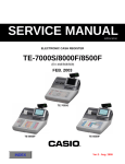
666 CIRCUIT EXPLANATION
66666 BLOCK DIAGRAM
Thermal
PRINTER
UNIT
PWB:E276-E22
Winder
Motor
Feed
Motor
AC Adaptor
PWB:
E276-E2
PWB:
E276-PR
DRAWER
UNIT
V850
JG3-L
E270-E4
FPC
FROM
2 Mbit
SRAM
256 kbit
PWB:
E274-E3
MODE
KEY
PWB: E276-1
DrySel Battery
RAC12
socket
RAC1
32 Mbit
— 31 —
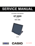
66666 LSI DIAGRAM
PWD
RESET
Local_BUS
CPU
uPD70F3738GC
-UEU-AX
AD0-AD7
A8-A14
A20(CS signal)
Multiplex
3.3V drive
SRAM 256kB
Data backup
20MHz
VDD=EVDD
= AVREF0 = AVREF1
=2.3 ~ 3.6V
Backup
Internal RTC
LED drive signal
Rear display ON/OFF Control
14 SEG LED
Main display only
7SEG LED
Main display and
Rear display
LED
Drive
Transaction
Drawer
Drive
BUZZER
KC4
SWITCH
KI0-7
KC4
KI4-KI7
KC0-3
KEY
SHEET
KC0-KC3, MODE COM
KI0-KI7
stb drive
Motor drive
Sensor
Thermal
printer
Journal and Journal
Drive
Wide
motor
Chip selection
3-line serial (Common)
Chip selection
EJ 256kB
Serial FROM 2MB
RAC12 4MB
Serial FROM 32MB
— 32 —
Journal Volume removing
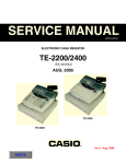
777 PCB LAYOUT
E276-1 PCB
E276-PR PCB
— 33 —
E276-E2 PCB (Main display)
E276-E22 PCB (Rear display)
— 34 —
888 CIRCUIT DIAGRAMS
MODEL : SE-S10/PCR-T280/PCR-T280L/PCR-T290L
(EX-276)
CONTENTS
1.MAIN PCB CIRCUIT.................................................................................................. 36
2.MAIN DISPLAY CIRCUIT.......................................................................................... 37
3.REAR DISPLAY CIRCUIT......................................................................................... 38
4.PRINTER I/F CIRCUIT............................................................................................... 39
— 35 —
CASIO COMPUTER CO.,LTD.
— 36 —
Model
EX-276
Board No.
E276-1
Name
MIAN BOARD
Drawing No.
RJE503230D303
CASIO COMPUTER CO.,LTD.
— 37 —
Model
EX-276
Board No.
E276-E2
Name
MIAN DISPLAY BOARD
Drawing No.
RJE503230D305
CASIO COMPUTER CO.,LTD.
— 38 —
Model
EX-276
Board No. Name
E276-E22 REAR DISPLAY BOARD
Drawing No.
RJE503230D306
CASIO COMPUTER CO.,LTD.
Model
Board No.
Name
EX-276
E276-PR
PRINTER I/F BOARD
— 39 —
Drawing No.
RJE503230D404
999 PARTS LIST
MODEL : SE-S10/PCR-T280/PCR-T280L/PCR-T290L
(EX-276)
CONTENTS
1.Explode view.................................................................................................................... 41
2.PARTS LIST.......................................................................................................................... 43
3.DRAWER S type (DL-1334/1843)....................................................................................... 45
4.DRAWER M type (DL-2811/2812)...................................................................................... 47
NOTES :
1. Price and specifications are subject to change withput prior notice.
2. As for spare parts order and supply, refer to the “GUIDEBOOK for Spare Parts Supply”, published separately.
3. The numbers in item column corespond to the same numbers in drawing.
4. CASIO does not supply the spare parts without parts code.
5. Remarks
Q'ty : Quantity used per unit
RANK: A = Essential
B = Stock recommended
C = Less recommended
X = No stock recommended
— 40 —
EXPLODED VIEW
8
6
9
5
1
4
29
14
15
27
3
2
26
13
S1
17
18
12
S2
32
31
22
16
BATERY BOX
33
S3
25
30
S2
S2
KEY BOARD ASSY
23
S2
11
S2
21
S2
24
7
10
S2
19
S1
20
S2
28
S1
S1
— 41 —
44
42
44
41
45
39
45
38
43
41
37
42
40
36
43
41
34
40
35
S4
— 42 —
N
N
N
N
N
N
N
N
N
N
N
N
N
N
N
N
N
N
N
N
N
N
N
N
N
N
N
N
Item
Part No.
1. FINAL ASSY
10345779
1
10345780
1
10345782
1
10347379
2
10326707
3
10349665
4
10285007
5
10347360
6
10325056
7
10254924
8
10325043
9
S1
2. U-CASE ASSY
10347303
10
10347342
10
10347311
10
10347316
11
10347351
12
63224499
13
10294939
14
10294940
15
10350060
16
10347321
17
10240554
18
10347330
19
10347323
20
10349673
21
10236317
22
10347345
23
10347346
24
10327860
25
10142488
26
10142489
27
10240926
28
10347352
29
10226189
30
10347329
31
10347349
32
33
33
10240096
33
10240097
33
33
S1
S2
S3
11 PCR-T280
12 PCR-T280L
13 PCR-T290L
6 SE-S10SB
7 SE-S10SBUA
8 SE-S10SBUG
9 SE-S10SBUK
10 SE-S10T
1 SE-S10MB
2 SE-S10MBUA
3 SE-S10MBUG
4 SE-S10MBUK
5 SE-S10MD
Part Name
Specification
BOARD/DISPLAY
BOARD/DISPLAY
BOARD/DISPLAY
ARRAY/KEY
COVER/BATTERY
PULLY/WIND
SPOOL/PAPER
COVER/PRINTER
SUB ASSY/TRAY
SUBASSY/KEY SET
SUBASSY/KEY SET
SCREW
RJE502996-005V03
RJE502996-006V03
RJE502996-007V03
RJE503262-001V01
RJE500211-001V03
RJE501880-001V04
RJE502545-001V01
RJE502997-003V01
RJE503008-001V01
RJE500074*002V03
RJE503007*002V01
S-BDST-3X8ZC
PCB ASSY/E276-1
PCB ASSY/E276-1
PCB ASSY/E276-1
PCB ASSY/E276-E2
CASE/UPPER
SPRING/BATTERY
SPRING/BATTERY
SPRING/BATTERY
SUB ASSY/BAT-CABLE
MOUNT/MOTOR
ASSY/MOTOR
MOUNT/PCB
SUPPORT/PCB
PLATE/FG
CUTTER/PAPER
MOUNT/PRINTER
ARM/EJECT
SW ASSY/MODE-KEY
ROLLER/P
ROLLER/P/D
FFC
ARM/PLATEN
PRINTER
HOLDER/POWER
UNIT/POWER
CORD/POWER
CORD/POWER
CORD/POWER
CORD/POWER
CORD/POWER
SCREW
SCREW
SCREW
RJE503222*001V01
RJE503222*002V01
RJE503222*004V01
RJE503224*002V01
RJE503254-001V01
A42606-1
RJE502620-001V01
RJE502622-001V01
RJE503227*001V02
RJE503259-001V01
E441295*003V01
RJE503260-002V01
RJE503267-001V01
RJE503298-001V01
E441364-001V02
RJE503266-001V01
RJE503261-001V01
E341249*004V01
RJE500850-001V01
RJE500851-001V01
E441341-010V01
RJE503264-001V01
LTPZ225B-C192-E
RJE503288-001V01
SO1258A
E (*B)
U (*C, L)
AR1CSEX270-UKLF
AR1CSEX270-SAA-ALF
U (*P)
S-BDST-3X8ZC
S-BDPT-3X8Z3
S-PAMA-2.5X4Z3
1
2
3
4
5
Quantity
6
7
8
9
Price
R
10 11 12 13 Code
1
1
1
1
1
1
1
1
1
1
1
1
1
1
1
1
1
1
1
1
1
1
1
1
1
1
1
1
1
1
1
1
1
1
1
1
1
1
1
1
1
1
1
1
1
1
1
1
1
1
1
1
1
1
1
1
1
1
1
1
1
1
1
1
1
1
1
1
1
1
1
1
1
1
1
1
1
1
1
1
1
1
1
1
1
1
1
1
1
1
1
1
1
1
1
1
1
1
1
1
1
1
1
1
1
1
1
1
1
1
1
1
1
1
1
1
1
1
1
1
1
1
1
1
1
1
1
1
1
1
1
1
1
1
1
1
1
1
1
1
1
1
1
1
1
1
1
1
1
1
1
1
1
1
1
1
1
1
1
1
1
1
1
1
1
1
1
1
1
1
1
1
1
1
1
1
1
1
1
1
1
1
1
1
1
1
1
1
1
1
1
1
1
1
1
1
1
1
1
1
1
1
1
1
1
1
1
1
1
1
1
1
1
1
1
1
1
1
1
1
1
1
1
1
1
1
1
1
1
1
1
1
1
1
1
1
1
1
1
1
1
1
1
1
1
1
1
1
1
1
1
1
1
1
1
1
1
1
1
1
1
1
1
1
1
1
1
1
1
1
1
1
1
1
1
1
1
1
1
1
1
1
1
1
1
1
1
1
1
1
1
1
1
1
1
1
1
1
1
1
1
1
1
1
1
1
1
1
1
1
1
1
1
1
1
1
1
1
1
1
1
1
1
1
1
1
1
1
1
1
1
1
1
1
1
1
1
1
1
1
1
1
1
1
1
1
1
1
1
1
1
1
1
1
1
1
1
1
1
1
1
1
1
1
1
1
1
1
1
1
1
1
1
1
1
1
1
1
1
1
1
1
1
1
1
1
1
1
1
1
1
1
1
1
1
1
1
1
1
1
1
1
1
1
1
1
1
1
1
1
1
1
1
1
1
1
1
1
1
1
1
1
7
7
7
7
7
7
7
7
7
7
7
7
7
13 13 13 13 13 13 13 13 13 13 13 13 13
13 13 13 13 13 13 13 13 13 13 13 13 13
— 43 —
C
C
C
C
C
A
A
C
C
C
C
A
A
A
A
C
C
C
C
C
C
A
C
C
C
C
C
C
C
B
B
C
C
A
C
C
C
C
C
C
C
N
Item
Part No.
11 PCR-T280
12 PCR-T280L
13 PCR-T290L
6 SE-S10SB
7 SE-S10SBUA
8 SE-S10SBUG
9 SE-S10SBUK
10 SE-S10T
1 SE-S10MB
2 SE-S10MBUA
3 SE-S10MBUG
4 SE-S10MBUK
5 SE-S10MD
Part Name
3. KEY BOARD ASSY
N 34
10335958 FRAME/KEY BOARD
10335946 CHASSIS/KEY BOARD
35
10335946 FPC
36
10335657 SPACER
37
10335956 SHEET/COMMON
38
10193646 SPRING/PRESS/B-E272
39
10193645 SPRING/PRESS/A-E272
40
10167457 RUBBER/CONTACT
41
10324975 KEY TOP /S
42
10324988 KEY TOP /L
43
10324989 CAPS/S
44
10324990 CAPS/L
45
SCREW
S4
Specification
RJE502981-001V02
RJE500682-002V03
RJE501097-001V02
RJE501103-001V03
RJE501100-001V02
E441298-002V03
E441298-001V03
RJE501209-002V01
RJE502974-001V01
RJE502979-001V01
RJE502975-001V01
RJE502980-001V01
S-WLPT-3X8ZC
1
2
3
4
5
Quantity
6
7
8
9
10 11 12 13
1
1
1
1
1
1
1
1
1
1
1
1
1
1
1
1
1
1
1
1
1
1
1
1
1
1
1
1
1
1
1
1
1
1
1
1
1
1
1
1
1
1
1
1
1
1
1
1
1
1
1
1
1
1
1
1
1
1
1
1
1
1
1
1
1
4
4
4
4
4
4
4
4
4
4
4
4
4
5
5
5
5
5
5
5
5
5
5
5
5
5
30 30 30 30 30 30 30 30 30 30 30 30 30
25 25 25 25 25 25 25 25 25 25 25 25 25
5
5
5
5
5
5
5
5
5
5
5
5
5
25 25 25 25 25 25 25 25 25 25 25 25 25
5
5
5
5
5
5
5
5
5
5
5
5
5
2
2
2
2
2
2
2
2
2
2
2
2
2
— 44 —
Price
R
Code
C
X
B
C
B
C
C
B
A
A
A
A
DRAWER S type (DL-1334 / DL-1843)
DL-1334
S4
S1
12
13
20
10
11
S5
DL-1843
S4
S5
S1
8
S2
S5
12
13
5
6
2
11
3
7
N1
9
N1
S3
4
W1
4
1
W1
18
1
S3
17
14
1
N2
19
N2
16
1
15
— 45 —
1 DL-1334
2 DL-1843
N
Descriptions
Item
Part No.
Part Name
1
2
3
4
5
6
7
8
9
10
11
12
12
13
14
15
16
17
18
19
20
W1
N1
N2
55000878
10201068
10194207
10167366
10080189
10259120
10260417
10267909
10317352
10324884
10298553
10231349
10231347
10276626
10238184
55801452
10120527
10298558
10298552
10317357
10324882
10080122
ROLLER/DELRIN
LOCK/SPRING
SPRING/PRESS
RUBBER/PAD
SUB ASSY/SOLENOID
LEVER/HOOK
AXIS/LEVER HOOK
SPRING/PLUNGER
CASE/MAIN
PLATE/FRONT
PLATE/PARTITION
SUB ASSY/BILL HOLDER
SUB ASSY/BILL HOLDER
SPRING/BILL HOLDER
RIVETS/COLD HEADED
CS FIX
SUB ASSY/CAM LOCK
CASE/COIN
SEPARATER/COIN
CASE/BILL COIN
COVER/TOP
WASHER
NUT
NUT
DR-19B2
RJE500007-001V02
E412137-001V02
RJE501204-001V01
E341255*2
RJE502182*001V01
RJE502184-001V01
RJE502245-001V01
RJE500670-003V05
RJE502970-001V01
RJE500214-002V03
RJE501337*002V03
RJE501337*001V03
E441357-001V03
T-CRTP-5X26Z3
CSTW-5
CL-16C
RJE500212-002V04
RJE500213-002V03
RJE500671-005V04
RJE502986-001V01
11.5X6.5XT0.8
6 ZMC-3
N-HXT2-6Z3
SCREW
SCREW
SCREW
SCREW
SCREW
3X8 ZMC-3,,
S-WBPT-4X25Z3
S-PAPT-3X22Z3
S-PAB0-3X8Z3
S-BDPT-3X6Z3
S1
S2
S3
S4
S5
— 46 —
QUANTITY
1
2
4
4
1
1
1
1
5
5
1
1
1
1
1
1
1
1
1
1
1
1
3
2
1
1
4
3
1
1
1
1
1
1
1
1
4
4
1
1
1
1
2
2
2
2
2
2
4
1
2
3
3
4
1
2
3
3
Price
Code
AF
AF
AA
AD
AV
AA
AA
BY
BI
AB
AR
AQ
AA
AA
AA
BA
AO
AA
BL
BP
R
B
C
C
C
B
C
C
C
B
B
C
X
X
A
X
X
C
C
C
X
X
DRAWER M type (DL-2811 / DL-2812)
16
DL-2811
S5
S4
S4
19
S4
18
17
23
20
DL-2812
24
S1 S2
S5
S4
S1
3
8
9
S1
S4
17
7
S1
4
19
18
11
5
S4
N2
W1
23
N1
21
2
22
20
9
N1
6
1
10
2
13
W2
10
15
S6
2
W2
12
14
S3
— 47 —
S3
1 DL-2811
2 DL-2812
N
Item
Part No.
Part Name
1
2
3
4
5
6
7
8
9
10
11
12
13
14
15
16
16
17
18
19
20
20
21
22
23
24
N1
N2
W1
W2
10324888
55000619
10236805
10127603
10201068
62465010
10078759
10078760
10194208
10167366
10080191
10203849
52000106
10272580
10324878
10200516
10225530
10230104
10276626
10194233
10298566
10298565
10298559
10298554
10298555
10324887
CASE/MAIN
ROLLER/DELRIN
LEVER/HOOK
AXIS/LEVER HOOK
LOCK/SPRING
SPRING/PRESS
RAIL/MLED18
RAIL/MRED18
RUBBER/DUMPER
RUBBER/PAD
SOLENOIDO SUB ASSY
DRAWER SUB ASSY
RIVET
LOCK/CYLINDER
PANEL/FRONT
BILL COIN CASE ASSY
BILL COIN CASE ASSY
SUB ASSY/ BILL HOLDER
SPRING/BILL HOLDER
PLATE/BILL HOLDER
CASE/BILL
CASE/BILL
CASE/COIN
SEPARATER/COIN
SEPARATER/BILL
COVER/TOP
6-NUT
6-NUT
WASHER
WASHER
RJE502983-001V01
DR-19B1
E341286-001V03
RJE500674-001V01
RJE500007-001V02
E412069-1
E240841-1
E240842-1
RJE500005-001V02
RJE501204-001V01
E341301*4
E341274*001V03
5X30
RJE502350*001V01
RJE502991-001V01
RJE501368*004V01
RJE501368*006V01
E341290*002V04
E441357-001V03
E240845-001V02
RJE500367-002V02
E140505-002V03
RJE500217-002V02
RJE500216-002V02
RJE500219-002V02
RJE502987-001V01
N-HXT1-6Z3
N-HXT1-4Z3
W-6X13-1.0Z3
6X13X1.0 ZMC-3
SCREW
SCREW
SCREW
SCREW
SCREW
SCREW
S-WSPT-4X10Z3
S-PADLMA-4X25Z3
3X10 NI
3X8 ZMC-3,,
3X5 NI...
S-BDPT-3X8Z3
S1
S2
S3
S4
S5
S6
Descriptions
— 48 —
QUANTITY
1
2
1
1
4
4
1
1
1
1
1
1
1
1
1
1
1
1
4
4
4
4
1
1
1
1
1
1
1
1
1
1
1
1
4
4
4
4
1
1
1
1
1
6
3
3
1
1
2
2
1
1
2
2
2
2
6
1
4
3
6
1
4
3
4
3
Price
Code
AG
AA
AF
AA
AD
AD
BC
AA
BW
AC
AA
AK
BK
AY
AA
AB
R
B
B
C
C
C
X
C
C
X
C
B
C
X
C
C
C
C
A
A
X
X
X
C
B
B
X
CASIO COMPUTER CO.,LTD.
Overseas Service Division
6-2, Hon-machi 1-Chome
Shibuya-ku, Tokyo 151-8543, Japan