1
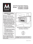
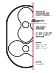
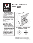
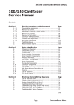
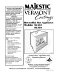
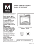
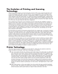
AS300/500 PRESSURE SEALER
Service Manual
SECTION 3
Operating
and
Service
Adjustments
Page 3 - 1
ISSUE 1 MAR 2001
AS300/500 PRESSURE SEALER
3.1.
PREVENTATIVE MAINTENANCE CHECK-LIST
3.1.1.
GENERAL
Service Manual
1. Ask how the machine has been working lately and use this information as a guide for
checking the machine.
2. Ask if there has been a change of use e.g. high volume production runs or a change of
material.
3. Check the operator adjustments of the machine and the material being processed.
4. Switch on machine and if any operating faults are occurring, clean all sensors and then
adjust (section 3.3.1).
5. If necessary, generally instruct the operators again with regard to their specific problem
area, and their maintenance responsibilities (see Operating Instructions section 8).
6. Enter the total forms count on the service sheet and alert your service department if the
machine is being used for more than 30,000 insertions per month.
7. When all service or repair operations have been carried out, the machine must be left
with all parts reassembled, leaving no risk of injury.
3.1.2.
REMOVAL OF COVERS
Note:Throughout this section, references to LH and RH are viewed standing
behind the hopper tray. The rear of the machine is the hopper end.
Some or all of the following covers may require removal for maintenance operations. Ensure all covers are undamaged. Check action of opening covers to confirm
correct operation, and that safety microswitches function correctly. Check that all
warning labels are legible. Exercise caution with moving parts and exposed electrical
apparatus when covers are removed.
1. Unplug main power supply lead from machine. Ensure that main power supply lead and
its connectors are sound and undamaged.
2. Remove LH side cover:- 2 x M4 screws/washers at front edge, 1 x M4 screw on tab in
front of hopper. 1 x M4 screw/washer at bottom of rear face. Lift bottom of cover
outwards then upwards to remove.
contd.
Page 3 - 2
ISSUE 1 MAR 2001
AS300/500 PRESSURE SEALER
Service Manual
3. Remove RH side cover:- Same as for LH cover.
4. Remove front vertical cover:- 2 x M4 screws/washers each side inside lower edge and
3 x M4 screws in face of cover. Exercise caution when removing due to sensor wires on
the inside - when cover is free, unplug the sensor wires to remove.
5. Remove rear electronics cover (under fold plate 2):- 4 x M4 screws/washers on lower
edge. When replacing, pass the studs that retain the hairsprings through the cutouts on
the top face, then slide the cover forward ensuring that the hairsprings press it down.
3.1.3. SERVICE AT EVERY SITE VISIT
1. Refer to section 3.1.1. ‘General’.
2. Remove all machine covers. (Section 3.1.2.).
3. Check spring tension and side guide action of hopper tray. Replace/adjust if
necessary. (Section 3.2.1).
4. Check that receiving tray moves smoothly and that spring plate is not broken.
5. Clean fold rollers using Roller Cleaning Fluid. Ensure they are cleaned across their full
width and round their full circumference.
6. Clean sealing rollers using an alcohol based cleaner. Check for surface damage or signs
of erosion.
7. Clean motor disk sensor under RH side cover (Section 3.2.5).
8. Check separator gap/action and adjust if necessary (Section 3.2.2).
9. Check condition of drive belt and ensure it is correctly tensioned. Replace if worn or
damaged (Section 3.2.6).
10. Check gear trains for backlash, which should be perceptible but minimal.
11. Check condition of anti-vibration mounts on subframe. Replace if worn or perished
(Section 3.2.9).
12. Check that all ‘T’ bearing springs are in place and unbroken. Replace if necessary.
13. Check for wear in all bearings, replace as necessary and lubricate.
14. Check security of all PCB connectors, including control panel and mains socket. Also check
motor connections (raise fold plate 2 to gain access).
15. Replace all covers.
Page 3 - 3
ISSUE 2 NOV 2003
AS300/500 PRESSURE SEALER
3.2.
MAINTENANCE AND ADJUSTMENTS
3.2.1.
FEED HOPPER
Service Manual
The feed hopper is fitted with a spring-loaded tray and side guides. If the tray has no tension
or is weak, the spring may be broken or flattened. To gain access, remove the screw and spigot in
the centre of the pivot shaft and also the 'E'clip at the LH end. Move the shaft leftwards to free the
other end, then lift out the tray and shaft, complete with the spring on the underside. This may then
be unclipped for replacement. Section 4.2 may assist when dismantling the tray.
The RH side guide is fixed and the LH guide moves within a limited range. The action should
be smooth, without being loose. To adjust, tighten or loosen the spring plate nuts on the underside
( refer again to section 4.2). The area under the spring plates should also be lightly greased.
When replacing the tray, ensure that the spring is properly located on the carrier studs.
3.2.2.
SEPARATOR ADJUSTMENT
The separator is spring loaded and is self-adjusting to an extent. However, it has a gap which
is initially factory set and may later require adjustment, which is not an operator function. There
is also a separator block which provides a degree of pre-separation - this is adjustable for rotation.
The block should be set first to provide a gap of .004 - .006" (0.1 - 0.15mm) between the rear tip
of the aluminium block and the roller, as shown in Fig. 1 below. The gap is then set so that a sheet
of 20lbs bond (80gsm) paper just grips as it is pulled through the gap by hand.
Access for both adjustments is underneath the hopper tray. The block screw is through a
central slotted hole, and the gap adjustment nuts are at each side. Slacken the block screw and use
the Allen key as a lever to rotate the block as required, tighten the screw then adjust each nut equally
to achieve the gap. Note that the block may need further fine adjustment if documents are still not
separating properly.
Fig. 1
Separator Replacement
If, after a long period of time, double documents are constantly being fed and adjustment
cannot cure this, it may be that the separator pad has worn out and will require replacement. As
the pad is permanently glued to the block, it cannot be replaced separately - the whole block must
be renewed.
Page 3 - 4
ISSUE 4 JAN 2005
AS300/500 PRESSURE SEALER
1.
Service Manual
Remove the infeed hopper tray by taking out the two pozi-pan head screws on each side
(inside the chassis face) and lifting out the tray - depress the tray against the spring to reach
the screws. The separator block will now be visible.
Block securing nuts
Separator block
Fig. 2
2.
Remove the two nuts shown in Fig. 2 above and slide the separator block and rod off the
screws.
3.
Fit the new block/pad to the rod and reassemble to the separator plate, ensuring that the
block is centrally located in the slot in the separator plate.
4.
Reassemble the feed hopper and adjust the separator block for rotation and gap, as described
in the preceding section.
3.2.3.
RECEIVING TRAY
The receiving tray slides in and out and is retained in position by a spring plate. If the action
is not smooth, too loose or notchy, the spring plate may require adjustment or replacement. To gain,
access, tilt the machine backwards on its rear edge, sufficiently to gain access to the underside.
Caution: ensure that the machine does not tilt too far, or it may topple. The spring plate is
retained with two self-locking nuts, which may be adjusted as required, or removed for spring plate
replacement.
Page 3 - 5
ISSUE 2 JUL 2004
AS300/500 PRESSURE SEALER
3.2.4.
Service Manual
FEED WHEEL REPLACEMENT
The feed wheels are located in front of the hopper, and feed the paper into the fold rollers.
The centre of the three feed rollers is directly above the separator pad. The feed wheels will need
replacing if they are visibly ragged or damaged, or constant misfeeds occur that cleaning cannot
remedy. The feed wheel shaft assembly is replaced as a whole.
Remove both side covers (section 3.1.2) and fold plate 1 assembly complete. To do this,
remove the 'E' clip at the RH end of the fold plate assembly pivot bar and also the screw at the LH
end. Push the assembly rightwards to free the 'D' end from the chassis (note that it may be tight),
then work the assembly free of the chassis.
On the RH side, remove the restrictor rings and spring, and then the 'E' clip and plastic bearing
at the end of the feed wheel shaft. On the LH side, pull out the clutch pin and slide the clutch and
gear off the shaft. Remove the 'E' clip and plastic bearing, and work the feed wheel shaft out of the
chassis.
Reassembly is a reversal of the above, noting the following: lightly oil the outer face of the
RH ‘T’ bearing and fit the 2 new restrictor rings with the spring between them. Note that the bosses
on the rings are directed inwards, and the outer ring is fitted with a grub screw. Compress the spring
so that the outer ring is 5mm in from the inner circlip groove in the shaft, then tighten the grub screw.
When replacing the clutch, ensure that the locator is between the two lugs on the clutch. Take care
not to damage the microswitch.
3.2.5.
DISC SENSOR
The disc sensor (for monitoring rotational speed) is located under the RH side cover (see Fig.
4 on the following page). As this is not readily accessible by the operator, cleaning it does not form
part of the Operator Maintenance, hence it must be cleaned by the PFE Service Engineer at service
visits.
To gain access to the disc sensor, remove the RH side cover (see section 3.1.2.); the disc
sensor is located at the bottom of the chassis, on the motor shaft. Note that the motor rotates in
a counter clockwise direction. Ensure both sides of the disc and the slotted sensor are cleaned using
the airduster.
Page 3 - 6
ISSUE 2 JAN 2005
AS300/500 PRESSURE SEALER
3.2.6.
Service Manual
DRIVE BELT ADJUSTMENT / REPLACEMENT
Remove the RH side cover and front vertical cover to gain access (section 3.1.2). The drive
belt should be adjusted to allow 3-4mm deflection each side. This can be gauged by inserting a 34mm dia. pin between the belt and a straightedge placed over the belt across the pulleys, in the
middle of its longest span. If adjustment is required, slacken the two motor screws A and B (see Fig.
4 below). The motor/drive pulley pivots about screw B - swing the upper end of the bracket
assembly to achieve the correct adjustment, then tighten the screws. Re-check the belt tension to
ensure it has not moved after tightening.
Drive belt
Screw A
Disc sensor
Screw B
Fig. 4
Drive belt replacement
The drive belt must be replaced if it is damaged or excessively worn. Remove the 2 plastic
rivets securing the disc sensor PCB and slacken the grub screw in the disc hub. Slide the disc and
PCB off the motor shaft. Remove screws A and B and withdraw the bracket assembly and belt,
looping the belt clear over the end of the drive pulley.
Fit the new belt and the bracket and replace screws A and B. The threaded holes in the end
of the motor plate may not align with the screws, as their removal frees the motor. To ease
alignment, raise the lower fold plate and manipulate the motor whilst doing up the screws.
Tension the belt as described above and reassemble the disc and PCB - ensure that the grub
screw aligns with the flat on the shaft and the disc is centrally located in the slot of the sensor.
3.2.7.
MOTOR REPLACEMENT
To replace the motor, remove the RH side cover, rear electronics cover and front vertical
cover (section 3.1.2). Remove the screw retaining the disc sensor bracket and move it clear of the
disc. Take off the drive chains and sprockets as described above. Reach inside to pull the two spade
connectors off the motor, and remove the tie bar behind the front vertical cover. Steady the motor
while removing its two retaining screws (see Fig. 4 above), and lift it out of the front.
Refitting is a reversal of the removal. After fitting, readjust the drive chains as described
above and lubricate if necessary. Ensure that the sensor disc is centrally located in the sensor.
Page 3 - 7
ISSUE 3 APR 2007
Service Manual
AS300/500 PRESSURE SEALER
3.2.8.
DIVERTER ADJUSTMENT
The purpose of the diverter is to eject double documents (and forms being calibrated) into
the diverter tray at the top of the machine so that they do not pass through the sealing rollers. It
is solenoid actuated and is controlled automatically by the software. It may need adjusting if forms
are not being diverted properly, are crashing at the diverter or the diverter tip is contacting the
sealing roller.
To adjust, remove the RH side cover to gain access to the solenoid (see Fig. 5 below). The
correct setting is for the tip of the diverter to be just clear of the sealing roller when the solenoid
is fully engaged and the plunger is bottomed. To adjust, raise fold plate 1 to reveal the top peak of
the diverter - the lower tip will also just be visible. Slacken the screws retaining the solenoid to the
chassis (located inside the chassis), hold the solenoid plunger fully bottomed and slide the solenoid
so that the tip shown in Fig. 5 is clear of the sealing roller by .008" - .012" (0.2 - 0.3mm). This can
be gauged by inserting two sheets of 20 lbs bond (80 gsm) paper until they are under the diverter
tip. This will necessitate holding the separator open by inserting a wedge between the separator
adjustment screw and the heel of the separator beam (see Fig. 2 on the previous page). Tighten the
solenoid screws while the tip is held down onto the paper, remove the paper and check that the
diverter does not contact the roller when the solenoid is engaged.
When adjustment is complete, replace the side cover and test the machine by running a double
document calibration - the folded, unsealed document should be ejected into the slot in front of fold
plate 1
Note: 0.008" (0.2mm) is equal to 2 thicknesses of 20lbs bond (80gsm) paper.
Solenoid
Diverter peak
Diverter tip
Solenoid link
Diverter
Sealing roller
Fig. 5
Page 3 - 8
ISSUE 1 MAR 2001
AS300/500 PRESSURE SEALER
3.2.9.
Service Manual
SUB-CHASSIS REMOVAL / REPLACEMENT
The pressure sealing rollers and motor are mounted within a sub-chassis, which in turn is
mounted into the main chassis using anti-vibration mounts. If the pressure roller bearings require
replacement, the subframe must be removed.
WARNING: The Sealing Rollers are extremely heavy and removal of the
subframe should not be undertaken without suitable assistance.
To make removal more manageable, it is advised that the following procedure is adhered to,
in the order stated. Notes should be taken of the positions of cable connectors prior to their removal.
1. Remove all covers (section 3.1.2.).
2. Remove fold plate 1 assembly complete. To do this, cut the cable ties securing the
divert sensor cable, trace the cable back to the PCB and unplug the connector. Remove
the 'E' clip at the RH end of the fold plate assembly pivot bar and also the screw at the
LH end. On the RH side, remove the screw securing the microswitch bracket. Push the
assembly rightwards to free the 'D' end from the chassis (note that it may be tight), then
work the assembly free of the chassis.
3. Unplug the solenoid cable from the control panel CPU.
4. Cut the cable ties securing the divert sensor cable from the pivoting front cover.
5. On the LH side, cut the cable ties securing the clutch cable to the chassis. Also remove
one end of the earth braid in the lower rear corner.
6. On the underside of the Control Panel PCB, remove the following connectors: J2, J3,
J8, J9 and J10 (see section 3.3.2 for connector identification).
7. Raise fold plate 2 and reach inside to unplug the 2 spade connectors to the motor.
8. Remove the 4 Allen screws securing the base of the sub-chassis to the main chassis (2
each side). With suitable assistance, lift the sub-chassis forwards and out (be aware of
the outfeed tray).
The sub-chassis can now be stripped as required (see section 4.5 for exploded view).
Sub-chassis Replacement
Replacement is a reversal of removal. Note that fold plate 2 will have to be lifted clear of the main
chassis when lifting the sub-chassis into position. Use new cable ties to secure the cables to the
chassis.
Page 3 - 9
ISSUE 1 MAR 2001
Service Manual
AS300/500 PRESSURE SEALER
3.2.10. SEALING ROLLER ADJUSTMENT
The front sealing roller is adjustable for tension, and while this is factory set re-adjustment
may be required after a long period of service, or if forms are failing to seal properly . A special tool
will be needed to perform this, and may be obtained by ordering part number A0277A.
To gain access to the adjusters, remove both side covers (section 3.1.2). The adjusters are
located at the upper front corners, as shown in Fig. 6 below. Back off the grub screw and slacken
both locknuts on the top of each adjuster. Using the special tool, turn the adjusting ring counter
clockwise until the ring is free from spring pressure (approx. 1 full turn). Now turn it back down until
contact with the springs is just felt, then a further 1 turn, applied 1/2 turn each side at a time.
Remove the tool and turn the lower locknut down until it contacts the adjusting ring, then a further
1 flat. Using two suitable wrenches, tighten the upper locknut onto it.
Repeat for the other adjuster and replace the side covers. Test the machine using MCP paper
and make fine adjustments if required.
Adjusting ring
Grub screw
Locknuts
Fig. 6
3.2.11. DISC SPRING REPLACEMENT
If adjustment of the sealing rollers as decribed in section 3.2.10 above does not resolve sealing
problems, the disc springs on the adjustable front roller may require replacement. To gain access
to the springs, remove the locknuts, washer and adjuster ring shown in Fig. 6 above. This will reveal
the disc springs, which may be removed using a probe magnet, or altenatively by pushing them up
from below using a fine screwdriver. There are 12 springs fitted on each adjuster, and these must
be fitted in the orientation shown in Fig.7 below. When the new springs are fitted, adjust as
described in section 3.2.10 above.
Adjuster block
Locknuts
Adjusting ring
Disc springs (12)
Fig. 7
Page 3 - 10
ISSUE 1 MAR 2001
AS300/500 PRESSURE SEALER
Service Manual
3.2.12. FOLD ROLLER REPLACEMENT
The fold rollers will require replacement if documents are constantly crashing or slipping in
the folder, and cleaning does not remedy the situation. There are three fold rollers, and it is possible
to replace all of them without removing the sub-chassis, although the lower rear roller (with fold
plate 2 attached to its shaft) is quite awkward to remove with the sub-chassis in place. Unless just
a single roller has incurred damage, all three rollers should be replaced together.
Removal of upper and lower front fold roller
1.
At each end of the roller, remove the 'E' clip, plastic bearing and spring (fitted only to upper
roller). It is now possible to work the roller out of the chassis.
Removal of lower rear fold roller
1.
If the sub-chassis has been removed, remove the 'E' clip at each end of the roller, followed
by the plastic bearing and spring. The roller can now be lifted out, complete with fold plate
2 attached. If the sub-chassis is to remain in place, proceed as shown below.
2.
Remove the upper fold roller to provide clearance (see above).
3.
On the LH side, remove the 'E' clip next to the plastic gear (note that the gear is retained to
the shaft with a pin behind it - this pin will be loose when the gear slides outwards).
4.
On each side, remove the 'E' clip next to the plastic bush retaining the fold plate. Slide the
plastic bushes outwards to allow the two fold plate components to be freed from the roller
shaft, and lift them out. The fold roller can now be worked out of the chassis. Note: this
method of removing the lower fold roller can be quite awkward, particularly when replacing
the plastic bearings - it is generally preferable to remove the sub chassis first.
Reassembly of all fold rollers is a reversal of their removal.
3.2.13. REPLACEMENT OF ANTI-VIBRATION MOUNTS
The anti-vibration mounts should be replaced as a set of four - if only one is worn or damaged,
the others will be nearing the same state. It is not necessary to remove the sub-chassis. Note that
the front (output) end of the machine is fitted with hard rubber mounts E0326A, and the rear end
is fitted with soft rubber mounts E0339A. This is essential due to the weight distribution - vibration
will result if the mounts are fitted incorrectly.
Remove and replace the mounts one at a time, by first removing the large cap head screw, then
the two smaller screws securing the mount to the main chassis. Lever or lift the sub-chassis upwards
to fit the new mount in place, and replace the screws. Repeat this procedure for each of the
insulators.
Page 3 - 11
ISSUE 1 MAR 2001
AS300/500 PRESSURE SEALER
3.3.
ELECTRONICS AND SOFTWARE
3.3.1.
SENSOR ADJUSTMENTS
Service Manual
All sensors apart from eject sensors are connected to the Control Panel PCB, the signals then
being routed to the CPU PCB via the ribbon cable between the two. To replace a sensor, cut
the cable ties securing it along the length of the cable, unclip the sensor from its housing and
replace with a new sensor lead assembly as indicated in section 5.1.
Sensors are adjusted on the CPU PCB mounted in the base of the machine, under the rear
electronics cover (see section 3.1.2 for removal). The voltage is measured between TPS pin
8 (0v) and TPS pin 1-4, depending upon sensor. Two readings are taken - with sensors clear
of paper and then blocked. The clear voltage is adjusted using the pot indicated. See section
5.1 for locations of sensors and section 3.3.2 overleaf for PCB physical layout, showing TPS
and adjustment pots. Note that TPS and the pots are located close to the rear edge of the
board, requiring only removal of the rear cover for access.
Sensors must first be cleaned before adjustment. If the settings shown cannot be achieved,
the sensor must be replaced.
Hold Point Sensor (TPS pin 1)
Adjust VR1 to give
0.3v between TPS pins 1 and 8 with sensors clear.
Now insert 20lbs bond (80gsm) paper between sensors to block fully.
Confirm
>4.0v
between TPS pins 1 and 8
Divert Sensor (TPS pin 2)
Adjust VR2 to give
0.3v between TPS pins 2 and 8 with sensors clear.
Now insert 20lbs bond (80gsm) paper between sensors to block fully.
Confirm
>4.0v
between TPS pins 2 and 8
Eject Sensor (TPS pin 3)
Adjust VR3 to give
0.3v between TPS pins 3 and 8 with sensors clear.
Now insert 20lbs bond (80gsm) paper between sensors to block fully.
Confirm
>4.0v
between TPS pins 3 and 8
Motor Disc (TPS pin 4)
Voltage between TPS pins 4 and 8 should alternate between <0.5v clear and >4.0v blocked
as disc is slowly turned.
Double Document
Double document sensor adjustment is carried out in Engineer Test Mode - see section 3.3.3
Page 3 - 12
ISSUE 2 APR 2008
AS300/500 PRESSURE SEALER
3.3.2.
Service Manual
PCB PHYSICAL LAYOUTS
Shown below are the layouts of the CPU and Control Panel PCBs used on this machine,
indicating the position of connectors, pots, pin header etc.
Connector TPS
Connector J4
CPU PCB 180-687 or 180-703
CONTROL PANEL PCB 180-688
Page 3 - 13
ISSUE 1 MAR 2001
AS300/500 PRESSURE SEALER
3.3.3
Service Manual
ENGINEER TEST MODE
Engineer Test Mode allows the engineer to carry out a variety of test functions and settings. To enter the mode, switch off the machine, fit a link (part no. 141-182-413) to J4 on the
CPU board and switch the machine back on. The display will indicate the scrolling message
'EnGInEEr' to confirm that Test Mode has been entered.
To step down through the various functions, press the Reset button
on the control
panel. A scrolling display will show the number and name of each test, as described below:
0. Panel Test:
Activates every display segment on the screen. If any are missing, the Control
Panel PCB must be replaced.
1. Button Test:
Identifies each button on the control panel as it is pressed. If any fail, the
Control Panel PCB must be replaced. Note that the Reset button cannot be
tested, as pressing this passes to the next function.
2. Covers Test: Indicates when a cover is opened, to test the microswitch.
3. Drive
Tests motor direction relay. Press the Run button to toggle motor ON or
Direction Test: OFF. Press the Calibrate button to choose direction. Display will show 'For'
= forward (normal), 'rEv' = reverse. Press the 'Stop' button to switch off
4. Solenoid
Test:
Also tests the motor and clutch. Press the Calibrate button to toggle between
the functions, and the Run button to switch the function on or off. Pressing
the Stop button stops all functions.
Display
Component
drOn (or drOFF)
FdOn (or FdOFF)
dvOn (or dvOFF)
Drive Motor
Feed Clutch
Diverter Solenoid
The clutch should be heard to click when activated, but as this is faint, touching the clutch whilst activating should confirm by feel. Alternatively, switch
on both clutch and motor and the feed rollers should rotate.
5. Sensors Test: Test sensors for blocked or clear condition. Displays the sensor name when
blocked with paper, or '- - -' when all are clear. Sensors tested are feed hold
point, eject and diverter.
6. Disc Test:
To test the disc sensor, the message 'Sc nn' will appear on the display, where
'nn' is the number of disc slots. This number will increase as the disc is
turned by hand, and should be exactly 30 for a complete revolution. Press
Stop to reset count, or Reset to continue.
Page 3 - 14
ISSUE 1 MAR 2001
AS300/500 PRESSURE SEALER
7. Double
Document
Setting:
Service Manual
Close all covers and place one sheet of 24 lbs bond pressure paper in hopper.
Press Run button twice to feed to hold point. Display will show 'dd nn' where
nn (or -nn) is a two digit number which, when the sensor is correctly set
equals 00 ±05. If not, adjust VR4 on the CPU board until this setting is
achieved.
8. Speed Test: Displays motor speed in RPM. Press the 'Run' button to start. Test lasts for
approx. seconds, then switches off.
9. Service
Count:
Sets the number of machine cycles at which the display will indicate to the
operator that a service is due. When first entered, the display will indicate the
last setting, which may either be a count or 'noSEr', which indicates that
Service Count has been disabled. To set a count (in units of 10), press the
Ddcal or Stop button to show 'xy000', where x & y can be changed. Use the
Stop button to increment 'x' and the Ddcal button to increment 'y'. To test
the function, press the Run button to indicate '00001' which will run 10 cycles after Engineer mode is exited, and the machine is run. Use the Run button to toggle between test count and 'noSEr'.
When activated, the display 'SErvICE dUE' will appear when the machine is
switched on, indicating to the operator that a service is due. Note: Changes
made to the service count will not be saved until the Reset button is pressed.
Press the Reset button to return again to the start of Engineer Test Mode. To exit finally,
switch the machine off and remove the link on J4. When next switched on, it will be ready to
run in normal mode.
3.3.4
SUPERVISOR MODE
Supervisor Mode reveals various statistics about the machine, namely Eprom version
number, total running hours and overall forms count. To enter the mode, press the Stop button
while the machine is displaying the 'HELLO' message after switching on. The message
'SUPErViSOr' on the display indicates that the mode has been entered.
To step down through the various functions, press the Reset button on the control panel.
The functions are described below:
Eprom:
Displays the Eprom version number in the format 'Vn-nn' where n-nn is the
version of the Eprom fitted to the CPU board.
Hours Count:
Displays the total number of hours to date that the machine has run. The
format is 'nnn_n' which equates to the number of hours (eg 082_7 means
82.7 total running hours to date).
Overall Count: Displays the total number of forms to date that the machine has processed.
The format is 'nnnnn' where nnnnn is the forms count in units of 100. Note
that this count is not reset by pressing the Zero Reset button.
Pressing the Reset button again displays the message 'End' to indicate that the end of
Supervisor mode is reached. Pressing the button again loops back to the start of Supervisor
Mode. Press the Stop button or switch off the machine to exit the mode.
Page 3 - 15
ISSUE 1 MAR 2001
AS300/500 PRESSURE SEALER
3.4
Service Manual
RECOMMENDED SPARES
The following list indicates the spares recommended to be held by Customer Service
Engineers. Quantities stated are for every 5 machines.
A complete set of spares can be obtained by ordering part No. A0280A for AS300
machines or A0278A for AS500 machines.
Recommended Spares (Mechanical).
PART NO.
DESCRIPTION
QTY
A0277A
A2663A
PRESSURE ADJUSTER TOOL
MOTOR 230V DC (SLEEVED)
1
1
B0064A
B0107A
SPRING PLATE
ANTI-STATIC BRUSH
2
1
C0038A
C8123A
C8131A
KEYWAY
FOLD ROLLER
INFEED SHAFT
2
3
1
D1039A
D1040A
SENSOR MOUNT
'T' BEARING HOUSING
3
12
E0326A
E0328A
E0329A
E0330A
E0338A
E0339A
E1056A
E1087A
E1101A
E1114A
E5071A
E5098A
ANTI-VIBRATION MOUNT (HARD)
1/4 TURN RETAINER
CLIP ON RECEPTACLE
M5 HANDWHEEL
DISC SPRING
ANTI-VIBRATION MOUNT (SOFT)
PL. OILITE 12 x 15 x 12
FLANGED BEARING
FLANGE BEARING
8mm BEARING
3 x 14 DOWEL PIN
3mm DRIVE PIN
2
1
2
1
24
2
2
2
2
3
2
2
F4205A
F4206A
F4211A
F5135A
15T CLUTCH GEAR
12T FOLD GEAR
12T REDUCTION GEAR
BELT 180-S3M-420PU
2
3
1
1
Page 3 - 16
ISSUE 4 JUL 2007
AS300/500 PRESSURE SEALER
Service Manual
Recommended Spares (Mechanical) contd.
PART NO.
DESCRIPTION
QTY
G0079A
G1023A
G1078A
G1116A
G1117A
G1137A
G1152A
G3339A
G6026A
G6050A
G6139A
CLUTCH PIN
SPRING, FOLDER
PLATFORM SPRING
SPRING, INTERMEDIATE PRESSURE
SPRING, HEAVY PRESSURE
SPRING, FINE PRESSURE
SOLENOID SPRING
CONTROL PANEL OVERLAY
INFEED GUIDE SHIM
12mm JOCKEY SHIM
GUIDE TAPE
3
1
2
2
2
2
1
1
2
6
1
Recommended Spares (Electrical).
PART NO.
DESCRIPTION
QTY
131-106
131-907
135-103
168-334
180-687
MICROSWITCH
EMERGENCY STOP SWITCH
FUSE, T3.15A
MAINS SWITCH, 4A
CPU PCB ASSY. (AS500)
OR
CPU PCB ASSY. (AS300)
SWITCH PCB ASSY.
MOTOR DISC SENSOR PCB ASSY.
SOLENOID
JST CLUTCH
OUTPUT SENSOR LEAD ASSY. (TX)
OUTPUT SENSOR LEAD ASSY. (RX)
ENGINEER LINK
H/POINT SENSOR LEAD ASSY. (TX)
H/POINT SENSOR LEAD ASSY. (RX)
DIVERT SENSOR LEAD ASSY. (RX)
DIV & D/DOC SENS. LEAD ASSY. (TX)
D/DOC SENSOR LEAD ASSY. (RX)
1
1
2
1
1
180-703
180-688
180-689
181-126
181-127
182-343
182-345
182-413
182-440
182-441
182-442
182-443
182-444
Page 3 - 17
1
1
1
1
1
1
1
1
1
1
1
2
1
ISSUE 2 JAN 2005
AS300/500 PRESSURE SEALER
Service Manual
SECTION 3.5 ERROR MESSAGES
If operating faults occur, a code will appear on the control panel display, for example:
where 'nn' = one of the numbers
indicated below.
The fault code will alternate with a scrolling description of the problem. If more than one fault
has caused the machine to stop, each code and description will cycle through before
repeating. If you press the 'Run' button while any error is displayed, you will be asked if you
wish to operate the Jog function (see Operating Instructions section 8.3)
FAULT CODE
DISPLAYED DESCRIPTION
ACTION TO TAKE
Flt1
Load hopper
Hopper is empty, or form not fed to
hold point. Reload, or check paper
is correctly loaded. Check feed
clutch.
Flt2
Feed fault
Paper jammed at infeed - clear
jam.
Flt3
Hand feed fault
Form not fully inserted when handfeeding. Ensure it is pushed fully
down.
Flt4
Doc did not arrive at divert
Form, (possibly a double or
calibration document) is jammed
in fold rollers or infeed - clear jam .
Flt5
Doc should not be at divert
Diverter solenoid may be stuck replace.
Flt6
Divert full
Unretrieved form is in divert/hand
feed slot - remove it.
Flt7
Doc did not arrive at eject
Form jammed on route to output clear jam.
Flt8
Doc failed to clear eject
Form cannot eject properly - check
output tray is correctly adjusted.
Flt9
Doc should not be at eject
Diverter solenoid may not be
operating - replace.
Flt10
Eject sensor obscured
Clean all sensors. Check form is
not blocking sensors.
Page 3 - 18
ISSUE 1 MAR 2001
AS300/500 PRESSURE SEALER
Service Manual
Flt11
Chip error
Fault with EPROM chip replace.
Flt12
Diverted double doc
Double document correctly
diverted. Remove, and check
paper in hopper is not stuck
together. Check separator gap.
Flt13
Undivertable double doc
Double document could not be
diverted - check for jam in fold
rollers.
Flt14
Ddcal fault
Clean double document
sensor, or call Service Dept. to
replace. Machine can only be
used for handfeed until fault is
fixed.
Flt15
Drive stall
Motor has stalled - ensure forms
do not exceed maximum
weight.
Page 3 - 19
ISSUE 1 MAR 2001
AS300/500 PRESSURE SEALER
3.6
Service Manual
ENGINEER'S TROUBLESHOOTING GUIDE
The following guide should be read in conjunction with that shown in the Operating
Instructions.
PROBLEM
SUGGESTED CAUSE AND REMEDY
1. Forms not feeding, although
machine is running.
1. Drive belt broken - replace. Infeed shaft clutch
faulty - replace.
2. Forms feeding skewed
2. Hopper tray misaligned - realign (section 3.2.1).
3. Double documents occurring
frequently.
3. Separator gap too wide or pad worn - reset gap or
replace separator block (section 3.2.2).
4. Jam occurring in folder.
4. Fault with fold plate or folder output sensors - check
voltages (section 3.3.1).
5. Fold rollers working erratically
or not at all.
5. Gear train damaged or too tight - check backlash
(section 3.2.5).
6. Document exits through top tray
but is not a double document.
6. Diverter solenoid stuck down - check action/adjustment
(section 3.2.8).
7. Double document not being
diverted but is entering rollers.
7. Restrictor on infeed shaft is too loose - adjust.
(section 3.2.4).
8. Documents not sealing, or failing
to seal completely.
8. Roller spring tension incorrect - check and reset
if necessary (section 3.2.10).
9. Documents not exiting sealing
rollers.
9. Roller skidding due to glazing - clean rollers.
Page 3 - 20
ISSUE 2 JAN 2005