1
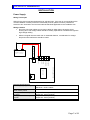
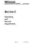
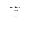
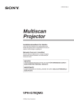
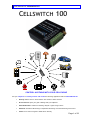
User Manual for Cellswitch 100 CELLSWITCH 100 CONTROL ANYTHING WITH YOUR CELLPHONE Use your cellphone to remotely monitor and control the following applications with the CELLSWITCH 100 Security: Electric Fence / Power-failure / Fire Sensors / Alarm Sensors Access Control: Open your gate or Garage with your cellphone Home Automation: Under-Floor Heating / Geyser / Lights / Plugs / Stove Industrial: Cold Room Monitoring / Temperature Monitoring / Process Monitoring and Control Farms: Pivot control / Irrigation / Water-level / Security Page 1 of 23 User Manual for Cellswitch 100 How does it work? The Cellswitch is a kind of cellphone you connect to an electronic appliance or device to enable you to communicate with it using your own cellphone. You insert a pre-paid or contract sim card into the Cellswitch and communicate with by sending it a SMS or by simply calling it, as you would SMS or call your friend. When the Cellswitch recognise your SMS or cellphone number it will respond in a certain way. Any Vodacom or MTN sim card may be used. How easy is it to use? Your cellphone communicates directly to your Cellswitch 100 with easy to understand SMS commands. Simply type a SMS with the words 1234.On and send it to the cellphone number of your Cellswitch and your lights, geyser, irrigation system etc will switch on from any where in the world!!! Simply SMS 1234.Off to switch it off again! Connect your Cellswitch to your gate or garage door and call it. You can now get access to your property or open the gate for the garden service without even being there. The call is free as the Cellswitch does not answer the call but simply recognises the calling number and disconnects the call automatically. Please note the Caller Line Identification must be enabled on your cellphone. What about security? Your Cellswitch will ONLY respond to you and your family’s saved cellphone numbers. The 1234 in front of every SMS command is a private PIN number that you can change whenever you want. How easy is it to program? Simply log onto our secure, easy to use website https://cellswitch.accentronix.co.za , register as a user, register your Cellswitch 100 by using the cellphone number of the sim card you are using and follow the easy to understand instructions. This method is great for a body corporate to add and remove security access control cellphone numbers at security complexes. This eliminates the need for remote controls as the Cellswitch can remember up to 500 cellphone numbers. Every time someone moves in or out, the body corporate simply log onto our website, add or remove those people’s cellphone numbers, hit update and DONE! How many different devices can I monitor and control? With the Cellswitch 100 you can monitor two different devices and control one at the same time. In other words you can monitor your alarm system, mains power and open and close your gate with a single device. When your alarm trips, it will SMS and call you, your family and your neighbours notifying them someone is busy breaking into your house. You can then phone your neighbour and open the gate for him remotely to go and investigate the situation. Getting Started: Step 1 > USING YOUR CELLPHONE ensure that the PIN number of the SIM card is disabled and there is airtime available on the SIM card before inserting it into the Cellswitch. Step 2 > Connect a switch or sensor between +12Vdc and Input 1. Step 3> Connect a 12Volt light or electronic appliance/device between +12Vdc and Relay COMMON. Connect Relay N/O (Normally Open) to 0Volt. Step 4> Connect Power. The LED will turn on for a couple of seconds and then start to flash. Step 5> Phone the number of the sim card inserted into the Cellswitch. You will hear the relay ‘click click’ on the Cellswitch and your call will automatically be disconnected. Step 6> Send a SMS with the text 1234.On to the Cellswitch and the relay will ‘click’ only once this time, staying on. In both steps 5 and 6 you will receive a confirmation SMS back from the Cellswitch. Step 7> Log onto https://cellswitch.accentronix.co.za/ to setup the device. This is a free service we offer to remotely program and manage the Cellswitch from our secure, easy to use website. Page 2 of 23 User Manual for Cellswitch 100 Important: Please read this information BEFORE installing the equipment. Intended Users This manual is to be available to all persons who are required to install or configure equipment described herein, or any other associated operation. The information given is intended to highlight safety issues, and to enable the user to obtain maximum benefit from the equipment. Personnel Installation and maintenance of the equipment should be carried out by qualified personnel. A qualified person is someone who is technically competent and familiar with all safety information and established safety practices; with the installation process, operation and maintenance of this equipment; and all the hazards involved. Hazards Warning! Failure to observe the following will constitute an Electrical Shock Hazard. The power supply connected to this equipment must be permanently earthed. Before working on the equipment, ensure isolation of the mains supply. When replacing a unit in an application and before returning to use, it is essential that all parameters for the product’s operation are correctly installed. This equipment contains electrostatic discharge (ESD) sensitive parts. Observe static control precautions when handling and installing this product. Equipment Inspection Check for signs of transit damage Check that the power supply and peripheral connected to this device conforms to the specified ratings as described in this document. If the unit is not being installed immediately, store unit in a well-ventilated place away from high temperature, humidity, dust, or metal particles. Foreword This manual contains text, diagrams and explanations which will guide the reader in the correct installation and operation of the Cellswitch 100 telemetry device. This document should be read and understood before attempting to install or use the unit. If in doubt at any stage of the installation of this device always consult a professional electrical engineer who is qualified and trained to the local and national standards which apply to the installation site. If in doubt about the operation of this device please consult the nearest AccentroniX distributor. This manual is subject to change without notice. Page 3 of 23 User Manual for Cellswitch 100 Table of Contents How does is work? 2 Caution 3 Key Features 5 System Requirements 6 Connection Diagram 6 Installation Power supply Sim card Antenna Physical Dimensions Digital Input Relay Output 7 7 8 8 8 9 10 SMS Configuration / Setup / Programming 11 General Specification 21 Diagnostics 22 Technical Support 23 Page 4 of 23 User Manual for Cellswitch 100 KEY FEATURES 2 x Digital Inputs To monitor alarms, sensors, etc. 1 x Relay Output To switch lights on/off, open gate/garage, etc. Controllable via voice-call Simply call the device with your cellphone to control the output. Confirmation SMS The device will send a confirmation sms back to your cellphone whenever it has been successfully programmed or when you switched its output on or off. 500 Programmable Cellphone security numbers Up to 500 programmable cellphone numbers can be recognized by the device when it is used for access control. Fully programmable via SMS commands The device is programmed by sending it SMS commands with your cellphone. 5 x Programmable reporting cellphone numbers The device can SMS and call up to 5 different cellphone numbers when its input is triggered. Daily input/output status report The device can send a daily report of its status to your cellphone. Machine-to-Machine interfacing Remotely connect I/O’s by using two or more Cellswitches to communicate with each-other. Page 5 of 23 User Manual for Cellswitch 100 SYSTEM REQUIREMENTS Programming: The Cellswitch is programmed by sending it sms messages from your cellphone containing specific commands. Whenever a valid command is received by the device, a confirmation sms will be sent back to you stating that the device was successfully programmed. If the device receives a random sms containing invalid data, the sms will be discarded and no sms will be sent back. When typing a command, make sure of the capital and small letters since the command will not be recognised if typed incorrectly. Power Supply: 12 Volt dc, 500mA. SIM Card: MTN or Vodacom, Pre-paid or Contract with PIN disabled. CONNECTION DIAGRAM SENSOR 2 RELAY N/O RELAY COM RELAY N/C CELLSWITCH 100 SIM CARD RS232 +12Vdc POWER SUPPLY 12V / 500mA 0V +12V INPUT 1 INPUT 2 0V GSM ANTENNA SENSOR 1 Page 6 of 23 User Manual for Cellswitch 100 INSTALLATION Power Supply: Wiring Techniques Wiring for the device has been designed to be safe and easy. If the user is concerned about the correct installation of these products or associated products, please contact a professional electrician who is trained to the local and national standards applicable to the installation site. Wiring Cautions Do not lay I/O signal cables next to power cables or allow them to share the same trunking duct. Low voltage cables should be reliably separated or insulated with regard to high voltage cabling. Max allowable momentary power failure period Average Power Consumption at 12Vdc: Average Power Consumption at 5Vdc: In-Rush Current RELAY N/O RELAY COM RELAY N/C CELLSWITCH 100 SIM CARD +12Vdc RS232 General Specifications Power supply (Regulated) 0V +12V POWER SUPPLY 12V / 500mA INPUT 1 INPUT 2 0V Where I/O signal lines are used over an extended distance, consideration for voltage drop and noise interference should be made. GSM ANTENNA Minimum: 5Vdc 500mA Maximum: 15Vdc 500mA Less than 10ms Output Off: 25mA (300mW) Output On: 45mA (540mW) Output Off: 40mA (200mW) Output On: 45mA (540mW) 500mA Page 7 of 23 User Manual for Cellswitch 100 SIM Card: Use any Vodacom or MTN pre-paid or contract sim. Disable the sim card’s pin number before installing it into the cellswitch. It is recommended to use a contract sim to avoid manual airtime top-up since most topup packages expire after three months if they are not re-charged at least every three months. We recommend the following month-to-month contract for R9.99/month especially tailored for telemetry devices at: http://www.mtn.co.za/FindaPlan/Pages/priceplan_new001.aspx?pkg=ProData For more information on acquiring the above contract, please contact us. Antenna: Do not install the Cellswitch 100 inside a metal enclosure unless the antenna sits on the outside of the enclosure. Physical Dimensions: Length = 77mm Width = 67mm Height = 28mm Page 8 of 23 User Manual for Cellswitch 100 Digital Inputs: When the input is triggered either high or low it will send a SMS to the programmed reporting numbers. Terminal “IN” is internally pulled low. Leaving the connection open or connecting it to “0V” will indicate an “Input-Low” state. When connecting terminal “IN” to either “+12V” or “Vout” will indicate an “Input-High” state. Terminal “Vout” is internally connected to “+12V”. Trigger voltage: Minimum = 3Vdc, Maximum = 25Vdc. SENSOR 2 RELAY N/O RELAY COM RELAY N/C CELLSWITCH 100 SIM CARD RS232 +12Vdc POWER SUPPLY 12V / 500mA 0V +12V INPUT 1 INPUT 2 0V GSM ANTENNA SENSOR 1 Page 9 of 23 User Manual for Cellswitch 100 Relay Output: The output is used to switch circuits on and off and is controlled by sending a sms from your cellphone to the Cellswitch 100. The output can also be control by calling the Cellswitch from your cellphone. When the device receives your call it will automatically disconnect you, handling it as a missed call at no charge to you. The output terminals are internally connected to a 2 Amp SPDT relay. N/C = Normally Closed COM = Common N/O = Normally Open Maximum Current Maximum Power Maximum Voltage 2 Amp 125VA, 60Watt 250Vac, 220Vdc N/O POWER SUPPLY 12V / 500mA N/C +12V COM 0V GSM ANTENNA NB: To increase the power rating of the output, connect a 12V high-current relay or contactor to the output terminals. RS232 INTERNAL SPDT RELAY Page 10 of 23 User Manual for Cellswitch 100 SMS Configuration / Setup / Programming IMPORTANT !!! PLEASE READ BEFORE ATTEMPTING TO PROGRAM THE DEVICE There are three different ways to program this device: 1.) Via our secure, easy to use, Gateway website https://cellswitch.accentronix.co.za/ 2.) By sending it SMS commands as described below. 3.) By connecting the device to a RS232 port on your PC. We recommend option 1 https://cellswitch.accentronix.co.za/ as this is a free service we offer and it is by far the easiest and most convenient. All the data is stored securely on our servers in a data centre. It is however important to understand the SMS I/O CONTROL COMMANDS section (right at bottom of this document) To use the website: 1.) Click on the link https://cellswitch.accentronix.co.za/ 2.) Register as a user. 3.) Register your device (using the cellphone number of the sim card inserted – pre-paid or contract) 4.) Configure the device settings 5.) Click on update on the bottom of the screen 6.) Our server will connect to the device, update its settings and save it in our secure database Option 2 and 3 at the top may be useful in the field if you are without internet connectivity and for testing the device. Please note that all settings will be overridden when using our website to program the device after programming via option 2 and 3. Programming the device via SMS Please follow the step-by-step instructions below: The device is programmed by sending it SMS messages from your cellphone containing specific commands. Whenever a command is received by the device, a confirmation SMS will be sent back to you stating that the device was successfully programmed. If the device receives a random SMS containing a wrong command or any other data, it will be discarded and no SMS will be sent back. When typing a command, make sure of the capital and small letters since the command will not be recognised if typed incorrectly. The ‘1234’ in front of every command is the default SMS password and it is recommended to change it when setting up the device. GENERAL SETUP SECURITY SMS REPORTING OPTIONS DIGITAL INPUT OPTIONS OUTPUT RELAY OPTIONS SMS I/O CONTROL COMMANDS Page 11 of 23 User Manual for Cellswitch 100 STEP 1 – Program the device’s own name, cellphone number and behaviour when it is called. GENERAL SETUP Device Name (Default: Cellswitch 100) 1234.F1"Cellswitch 100" The device's name displayed in the SMS reports. Device’s own cellphone number 1234.F2"0827727789" Programs the sim cards cellphone number onto the unit Switch the relay output when a call is received (Default) 1234.F3a When a voice call is received, the relay output will be switched Enable/Disable the inputs when a call is received 1234.F3b When a voice call is received, the inputs will be enable/disabled Page 12 of 23 User Manual for Cellswitch 100 STEP 2 – Program the desired security settings. SECURITY Add security numbers 1234.F4a”0827727789;0825091827;” When the unit is used for access or remote control. Only these cellphone numbers will be accepted by the unit when it is called. Note the semicolon at the end of each number. Up to 8 numbers may be added in one SMS. Delete a security number. 1234.F4b”0827727789;0825091827;” Remove the programmed security numbers using this command. Note the semicolon at the end of each number. Up to 8 numbers may be removed in one SMS. Enable security 1234.F4on The relay output will only switch when a programmed security number calls the device. Disable security (Default) 1234.F4off The relay output will switch when any cellphone number calls the device. SMS programming password (Default: 1234) 1234.F5a”5678” Changes the default SMS password from 1234 to 5678. F5b reserved for SIM PIN Page 13 of 23 User Manual for Cellswitch 100 STEP 3 – Program the cellphone numbers the device must SMS when an input is triggered. SMS REPORTING OPTIONS 1234.F6a”0827727789” SMS Reporting number 1 Programs the first number to SMS and/or dial when an input is triggered. SMS Reporting number 2 1234.F6b”0827727789” Programs the second number to SMS and/or dial when an input is triggered. SMS Reporting number 3 1234.F6c”0827727789” Programs the third number to SMS and/or dial when an input is triggered. SMS Reporting number 4 1234.F6d”0827727789” Programs the fourth number to SMS and/or dial when an input is triggered. SMS Reporting number 5 1234.F6e”0827727789” Programs the fifth number to SMS and/or dial when an input is triggered. Send daily SMS Status report 1234.F7on A SMS will be sent daily containing input/output and GSM signal status. Do not send daily SMS Status report (Default) 1234.F7off A SMS will NOT be sent daily containing input/output and GSM signal status. 1234.F7”12:00:00” Daily SMS Status report time (Default: 12:00:00) The time the hh:mm:ss the daily status report must be sent. Page 14 of 23 User Manual for Cellswitch 100 SMS REPORTING OPTIONS --- CONTINUED Send Power-up SMS report 1234.F8on When the power to the device was interrupted it will send a notification SMS when power is re-applied. Do not send Power-up SMS report (Default) 1234.F8off When the power to the device was interrupted it will NOT send a notification SMS when power is re-applied. Send a Power-up Report to user 1 only (Default) 1234.F8a When the power-up SMS report is enabled, it will send a SMS to reporting number 1 only. Send a Power-up Report to all reporting numbers. 1234.F8b When the power-up SMS report is enabled, it will send a SMS to all five reporting numbers. Page 15 of 23 User Manual for Cellswitch 100 STEP 4 – Program the SMS messaged that will be sent when the inputs are triggered. DIGITAL INPUT OPTIONS Input 1 high SMS 1234.F9a”Sensor 1 triggered” The SMS that will be sent when Input 1 is High (5 to 24 volt). Input 1 low SMS 1234.F9b”Water level LOW ” The SMS that will be sent when Input 1 is Low (0 volt or not connected). Input 2 high SMS 1234.F9c”Power restored” The SMS that will be sent when Input 2 is High (5 to 24 volt). Input 2 low SMS 1234.F9d”Power tripped ” The SMS that will be sent when Input 2 is Low (0 volt or not connected). Input trigger (high) - (Default) 1234.F10a A SMS will only be sent when an input goes high (5 to 24 volt). Input trigger (high and low) 1234.F10b A SMS will be sent when an input goes high or low. Input trigger (low) 1234.F10c A SMS will only be sent when an input goes low (0 volt or not connected). SMS the reporting numbers (Default) 1234.F11on The device will SMS the reporting numbers when an input is triggered. Do not SMS the reporting numbers 1234.F11off The device will not SMS the reporting numbers when an input is triggered. Page 16 of 23 User Manual for Cellswitch 100 DIGITAL INPUT OPTIONS --- CONTINUED Call the reporting numbers 1234.F12on The device will first SMS, then call the reporting numbers when an input is triggered. Do not call the reporting numbers (Default) 1234.F12off The device will only SMS and not call the reporting numbers when an input is triggered. Enable the inputs (Default) 1234.F13on / 1234.Arm If an input is triggered, a SMS will be sent. Disable the inputs 1234.F13off / 1234.Disarm If an input is triggered, no SMS will be sent. Inputs enabled message 1234.F13a"Alarm armed" When the inputs are enabled, this confirmation SMS will be sent back. Inputs disabled message 1234.F13b"Alarm disarmed" When the inputs are disabled, this confirmation SMS will be sent back. Input 1 trigger delay time (Default: 0) 1234.F14"3" The time in seconds input 1 must be triggered high before a SMS is sent. The delay only works on input 1. It also only works when input 1 is HIGH, NOT on LOW. (Max: 24hrs or 86400seconds) Page 17 of 23 User Manual for Cellswitch 100 STEP 5 – Program how the output relay must behave when the device is called or sent a SMS. OUTPUT RELAY OPTIONS 1234.On Switch the RELAY OUTPUT ON 1234.Off Switch the RELAY OUTPUT OFF Output PULSE mode (Default) 1234.F15a When a voice call is received the output relay will PULSE once (Switch on and then off again) Output TOGGLE mode 1234.F15b When a voice call is received the output relay will TOGGLE (Switch either on or off) Output relay PULSE duration (Default: 1) 1234.F15”5” Programs the output relay's PULSE duration in seconds when the device is called i.e. it will switch on for 5 second and then off again (Max: 24hrs or 86400seconds) Send output switching confirmation SMS 1234.F16on When the unit is called/sms'd and the output relay is switched a confirmation SMS will be sent back. Do not send output switching confirmation SMS (Default) 1234.F16off When the unit is called/sms'd and the output relay is switched no SMS will be sent back. Page 18 of 23 User Manual for Cellswitch 100 OUTPUT RELAY OPTIONS --- CONTINUED Output relay switching ON confirmation SMS 1234.F16a"Lights switched on" When the unit is called and the output relay is switched on, this confirmation SMS will be sent back. Output relay switching OFF confirmation SMS 1234.F16b"Lights switched off" When the unit is called and the output relay is switched off, this confirmation SMS will be sent back. Output relay switching PULSE confirmation SMS 1234.F16c"Gate Opened" When the unit is called and the output relay pulsed, this confirmation SMS will be sent back. Remember Relay Output Status (Default) 1234.F17on When power to the device was cycled, the output relay will switch to the same state prior to the power interruption. Do not remember Relay Output Status 1234.F17off The relay outputs will be reset to off when the device power was cycled. Page 19 of 23 User Manual for Cellswitch 100 STEP 7 – Test the device by checking GSM signal strength, inputs and outputs. SMS I/O CONTROL COMMANDS 1234.Status Request Input/Output and signal quality status. 1234.Signal Requests the GSM signal strength 1,0 = Bad Signal. 30,0 = Full signal 1234.Airtime Requests the remaining airtime on a pre-paid sim. 1234.On Switch the RELAY OUTPUT ON 1234.Off Switch the RELAY OUTPUT OFF Enable the inputs 1234.Arm If an input is triggered, a SMS will be sent. Disable the inputs 1234.Disarm If an input is triggered, no SMS will be sent. Page 20 of 23 User Manual for Cellswitch 100 General Specifications: Operating Temperature Storage Temperature Operating Humidity Storage Humidity Vibration Resistance - Direct Mounting Shock Resistance Noise Immunity Dielectric Withstand Voltage Insulation Resistance PSU Ground -10ºC to +50ºC -40ºC to +70ºC 35 to 85% Relative Humidity, No Condensation 35 to 90% Relative Humidity, No Condensation 10 to 57 Hz: 0.075mm Half Amplitude 57 to 150 Hz: 4.9 m/s² Acceleration Sweep Count for X, Y, Z: 10 times (80 min. in each direction). 4.9 m/s² Acceleration, Action Time: 11ms 3 times in each direction X, Y, Z 1000 Vp-p, 1 µS, 30 to 100Hz 1500 Vac > 1 minute, tested between all points, terminals and ground. 5Mohm > at 500 Vdc, tested between power terminals and ground. Grounding resistance 100ohm or less. Caution Units should not be installed in areas subject to the following conditions: excessive or conductive dust, corrosive or flammable gas, moisture or rain, excessive heat, regular impact shocks or excessive vibration. Do NOT use this equipment for medical or mission critical applications as the cellphone networks supply a best effort service and may not always be online. Always use a failsafe system in conjunction with this device. Take special care not to allow debris to fall into the unit during installation e.g. cut wires shavings etc. Always ensure that the mounted unit is kept as far away as possible from high-voltage cables, high-voltage equipment and high-voltage power equipment. Do not lay signal cables near high-voltage power cabling or cabinet housing along the same trunking duct. Effects of noise or surge induction may occur. Keep signal cables of more than 100mm (3.94”) away from these power cables. Cut of all phases from the power source before installation or performing wiring work to avoid electrical shock. Incorrect operation can lead to serious damage to the product. Cut of all phases from the power source before installing/removing extension or communication cables to modules to avoid electrical shock, incorrect operation or serious damage to product. Replace the terminal cover provided, after insulation or wiring work is completed, and before supplying power and operating the unit to avoid electrical shock. When using an incorrect power source or performing incorrect operation, serious damage will occur regardless of the level of the voltage and frequency. During transportation avoid any impact as the Cellswitch is a precision instrument. It is necessary to check the operation of the Cellswitch after transportation, in case of any impact damage. When storing the Cellswitch, conform to the environmental conditions specified by the general specification. Terminal screws should be tightened to between 0.5 and 0.8 Nm up to a maximum of 1.2Nm. Screws must be secured to prevent a loose connection thus avoiding a malfunction. Page 21 of 23 User Manual for Cellswitch 100 Diagnostics Preliminary Checks Before Power up Power the device up □ Check 230Vac Power Supply Wiring □ Check Ground Wiring □ Check Digital Input Wiring □ Check Relay Output Wiring □ Check Sim Card Check that Power LED turns on for about 10 seconds, then start flashing. During Testing During this testing stage take extreme care not to touch any live or electro-static sensitive parts. LED Indicator Status LED On Power-up the LED will stay on for about 10 seconds then start flashing. If the LED does not start flashing and stays on, do the following checks: □ Check that the SIM CARD is installed properly. □ Check that the SIM CARD PIN is disabled. □ Check that the ANTENNA is installed properly. □ Check SIGNAL STRENGTH. Maintenance Do Preliminary Checks Page 22 of 23