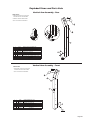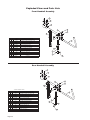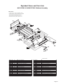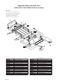
1
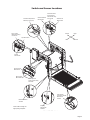
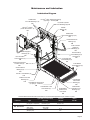
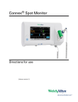
Service Manual for:
C8A
Century 2
HZg^Zh
Public Use Wheelchair Lifts
Series BB
DOT — Public Use Lift
“DOT — Public Use Lift” verifies that this platform lift meets the
“public use lift” requirements of FMVSS No. 403. This lift may be
installed on all vehicles appropriate for the size and weight of the
lift, but must be installed on buses, school buses, and multipurpose passenger vehicles other than motor homes with a gross
vehicle weight rating (GVWR) that exceeds 4,536 kg (10,000 lb).
33220
WARNING
Man
l
®
®
International Corporate Hdqrs: P.O. Box 310 Winamac, IN 46996 USA
1-800-THE LIFT ®
(574) 946-6153
FAX: (574) 946-4670
Patent #5,261,779
Patent #6,599,079
34645
Patent #6,065,924
Patent #6,692,217
February
Patent #6,238,169
Patent #6,739,824
2008
Patent #6,464,447
Patents Pending
Read manual
before installing
or servicing lift.
Failure to do so
may result in
serious bodily
injury and/or
property damage.
Braun Century 2 Series
"Providing Access to the World"
ua
Congratulations
We at The Braun Corporation wish to express our fullest appreciation
on your new purchase. With you in mind, our skilled craftsmen have designed and
assembled the finest lift available.
This manual provides service-related material. Refer to the FMVSS No. 403
Quick Reference Installation Sheet for installation instructions, operating instructions
and maintenance procedures.
Braun Century Series™ lifts are built for dependability and will provide years of
pleasure and independence as long as the lift is installed and serviced as specified by
a Braun certified technician, and the lift is operated by an instructed person.
Sincerely,
THE BRAUN CORPORATION
Ralph W. Braun
Chief Executive Officer
Warranty and Registration Instructions
Immediately upon receiving the lift, examine the
unit for any damage. Notify the carrier at once
with any claims.
Series No.
Pump Code
Model No.
Serial
No.
Cylinder Code
War.
Card 07.ai
OWNER'S WARRANTY REGISTRATION
NCL917IB-2
Two warranty/registration cards (shown right) are
located in the lift-mounted manual storage pouch.
The sales representative must process one of the
cards. The consumer must fill out the other card
and mail it to The Braun Corporation. The warranty is provided on the back cover of this manual.
The warranty cards must be processed to
activate the warranty.
BB-00025
66
14BI
PURCHASED FROM
OWNER
DATE INSTALLED
NAME
ADDRESS
CITY
TELEPHONE
STATE
ZIP
TO VALIDATE WARRANTY
REGISTRATION CARDS MUST BE RETURNED TO THE BRAUN CORPORATION.
Sample Warranty/Registration Card
Two Braun Serial No./Series No. identification tags (shown below) are posted on the lift.
One I.D. tag is posted on the opposite pump side vertical arm. A second I.D. tag is located
on the opposite pump side tower. Both I.D. tags provide the product identification information provided on the warranty/registration card. Record the information in the space
provided (or document on a copy). This information must be provided when filing
a warranty claim or ordering parts.
The Braun Corporation
1-800-THE LIFT™
BRAUNLIFT.COM™
DOT Public Use Lift MODEL#
NCL917IB-2
Max. Lifting Capacity - 800 lbs.
Model No.
Series No.
SERIAL NUMBER
BB-00025
PUMP CODE
66
CYLINDER
MFG DATE
14BI
01/25/08
e5*72/245*95/54*0110*00
PATENT
PENDING- 5,261,779-6,065,924-6,238,169-6,46
4,447-6,599,079-6,692,217-6,739,824
Sample Serial ID
No./Series
No. Identification Tag
Tag NCL2-BB.ai
Serial No.
Pump Code
Cylinder Code
Date of Manufacture
Contents
Troubleshooting and Maintenance
Lift Terminology............................................................. 2
Switch and Sensor Locations ...................................... 3 Certification Checklist Diagnostic Procedures........... 4
Platform Fold Pressure Adjustment............................. 5 Platform Angle Adjustment ....................................... 6-7
Platform Stop Blocks .................................................... 7
Tower Microswitch Adjustment..................................... 8
Lubrication Diagram....................................................... 9
Maintenance and Lubrication Schedule................10-13
Notes............................................................................. 14
Lift Electrical Schematic ............................................. 15
Lift Wiring Diagram ..................................................... 16
Hydraulics
Hydraulic Schematic ................................................... 17
Hydraulics Parts List . ................................................. 18
Hydraulics Diagram . ................................................... 19
Repair Parts
Pump Module
Pump Module Parts List ........................................ 20
Pump Module Diagram .......................................... 21
Lift Exploded Views and Parts Lists
NCL917IB-2 Base Plate Assembly . ...................... 22
NCL917FIB-2 Base Plate Assembly . .................... 23
NCL919IB-2 Base Plate Assembly . ...................... 24
NCL919FIB-2 Base Plate Assembly . .................... 25
Top Parallel Arm Assembly.................................... 26
Bottom Parallel Arm Assembly.............................. 27
Hydraulic Cylinder Assembly - Main..................... 28
Vertical Arm Assembly........................................... 29
Handrail Assembly.................................................. 30
NCL917IB-2 & NCL917FIB-2 Platform Assembly..... 31
NCL919IB-2 & NCL919FIB-2 Platform Assembly..... 32
Page Lift Terminology
Towers (2)
Pump Module
(Rear)
Visual
Threshold
Warning
Hand-Held
Pendant
Control
Top Parallel Arms (2)
Main Cylinders (2)
Audible
Threshold
Warning
Adjustable Quiet-Ride Stow Blocks (2)
(not visible)
Unfold Assist Compression Springs (2)
Lift-Tite™
Latches (2)
32819
UP
FOLD
Platform Lights (2)
Vertical Arm Covers (4)
DOWN
LD
UNFO
32820
®
Threshold
Warning
Plate
Handrails (2)
Opposite Pump Side
Vertical Arm
Base Plate
Inner Roll Stop
Bottom Parallel
Arms (2)
Saddle (2)
Inner Fold Arm (2)
Platform
Outer Fold Arm (2)
Pump Side
Vertical Arm
Platform Side Plates (2)
Outer Barrier
Outer Barrier Latch
Inboard
Left
Inboard
(driver's side)
Rear
(of vehicle)
Page Right
Outboard
Front
(of vehicle)
Outboard
(passenger's side)
“Arrows/30°-30°”6-13-90
NCL917IB2-BB-003.ai
Switch and Sensor Locations
Threshold Strip Switch
33337A (2 strips per)
*Threshold Alarm
& Partial Fold
Microswitch Assy.
*Threshold Alarm 975-3121A
*Partial Fold
Microswitch
Microswitch
*Up & Unfold
Microswitch Assy.
975-3121A
Inboard
*Up Microswitch
Left
32819
UP
FOLD
Right
Outboard
DOWN
D
UNFOL
32820
®
*Unfold
Microswitch
Stow Interlock
Microswitch
IB Occupied
Microswitch
IB Occupied &
Stow Interlock Assy.
32514NA
Outer Barrier
Occupied / Raised
Microswitch
33775A
IB Raised Switch
32519A
*Note: Mirror image for
right (front) pump lifts.
Bridging
Microswitch
33689A
NCL917IB2-BB-033.ai
Page Certification Checklist Diagnostic Procedures
The following operations and conditions must be functionally verified in order for the lift to be FMVSS
403/404 compliant. If an operation does not function as described or a condition is not met, follow the referenced procedures to correct the problem or contact a Braun Corporation Product Support representative at
1-800-THE LIFT®.
• Vehicle movement is prevented unless the lift door is closed, ensuring the lift is stowed.
1. Verify on the pump module mounted interlock connecter that the lift stowed signal - pin 9 has a
ground signal OR lift not stowed signal - pin 5 has an open signal (depends on interlock used).
2. Refer to the interlock installation instructions.
• Lift operation shall be prevented unless the vehicle is stopped and vehicle movement is prevented.
1. Verify vehicle secure signal (pin 6) has a +12 volt signal.
2. Refer to the interlock installation instructions.
• The platform will not fold/stow if occupied.
- Refer to Platform Fold Pressure Adjustment procedures.
• The inner roll stop will not raise if occupied.
- Call Product Support
• The outer barrier will not raise if occupied.
- Refer to Outer Barrier Fold Pressure Adjustment procedures.
• Verify platform lighting when lift is deployed and pendant illumination when lift is powered.
1. Replace bulb(s) in the light housing.
• A visual and audible warning will activate if the threshold area is occupied when the platform is at least one
inch below floor level.
1.
2.
3.
4.
Remove the threshold warning plate
Verify the threshold strip switch connectors are connected
Replace the threshold strip switch
Reinstall the threshold warning plate
• Platform movement is prohibited beyond the position where the inner roll stop is fully deployed (up).
- Call Product Support.
• Lift platform movement shall be interrupted unless the outer barrier is deployed (up).
- Call Product Support.
Page Platform Fold Pressure Adjustment
1. Position the platform at the floor level loading position.
2. Loosen the hex nut on the adjustment screw (do not remove hex nut).
3. Turn the adjustment screw counter clockwise until the platform does not fold when the Fold button is
pressed.
4. Turn the adjustment screw clockwise in 1/4 turn increments and press the Fold button until the platform folds completely (Note: Return the platform to floor level position after each attempt to fold the
platform).
5. Turn the adjustment screw an additional 1/8 turn after the platform folds successfully.
6. Tighten the hex nut without moving the adjustment screw.
7. Verify the platform will not stow while occupied.
Platform Fold
Adjustment
Allen Screw
DO NOT
DO NOT
adjust
adjust
this valve!
this valve!
(Located
(Located
beside
beside
Solenoid
Solenoid
Valves)
Valves)
Note: Secure adjustment
screw and tighten hex
nut following adjustment.
Page Platform Angle Adjustment
Adjusting the platform angle based on the
relationship of the platform at ground level
directly affects the angle of the platform
when positioned at floor level.
Millennium “NL” Series
Figure C
Unfold the lift and visually examine the
angle of the platform when positioned at
floor level. Lower the platform fully and
note the angle of the platform when it
reaches ground level also. The outboard
end of the platform (toe) must contact
the ground first when the platform is
lowered (all lift models).
Angle A
equals
Angle B.
✓
Millennium “NL” Series:
The platform angle should be adjusted so
there is a balance between the angle at
both positions (equal amount of angle).
Angle A should equal angle B as shown
in Figure C.
Century “NCL” Series:
Vista “NVL” Series:
The platform angle must be adjusted so
the outboard end of the platform (toe) is
angled down slightly when positioned at
floor level. See Figure D. The outboard
end of the platform must contact the
ground first to ensure the spring-loaded
outer barrier unfolds fully.
A
Wedges
B
Approximately
1" Clearance
Inboard
Outboard
Century “NCL” Series
Vista “NVL” Series
Adjustment Procedures: Adjustment
Allen screws are provided on each side of
the lift platform for adjusting the platform
angle. Details and photos are provided
on the opposite page.
Figure D
Base Plate Wedges: Installations where
base plate wedges are used require more
platform angle adjustment than normal.
Toe must
angle
down
slightly.
Platform Stop Blocks: When adjusting platform angle, ensure both
stop blocks are making full contact
with the vertical arms (details on
opposite page).
Floor Level Adjustment: Following
platform angle adjustment, set floor
level positioning as detailed in Tower
Microswitch Adjustment (details on
page 8).
Page Barrier
must
unfold
fully.
Wedges
Inboard
Outboard
Inboard
(driver's side)
Rear
(of vehicle)
Front
(of vehicle)
Outboard
(passenger's side)
Platform Angle Adjustment
Adjustment Allen screws are
provided on each side of the lift
platform for adjusting the platform
angle. Adjust platform angle as
specified on previous page.
To raise the outboard end
of platform - turn adjustment
screw clockwise.
Note: Both adjustment screws
must be adjusted equally.
Apply Loctite® to adjustment
screws following adjustment.
To lower the outboard end
of platform - turn adjustment
screw counterclockwise.
Platform Angle
Adjustment Screws
Adjustment Screw
Allen Head
B
A
Turn
counterclockwise
to lower
outboard
end of
platform
Turn
clockwise
to raise
outboard
end of
platform
Platform Stop Blocks
Right
Must make full contact.
Gap not permitted.
Wrong
Stop Block Guideline
All Lift Models
Vertical Stop
Arm Block
C
Both stop blocks must
make full contact with
the edge of vertical arms.
When adjusting platform
angle, setting floor level
position or adjusting
bridging microswitch ensure both stop blocks
are making full contact
with the vertical arms.
Vertical
Arm
Stop
Block
D
Page Tower Microswitch Adjustment
TOWER
TOWER
4
TOWER
3
32943
1
32942
TOWER
Figure E
TOWER
4
3
32943
Note:TOWER
Review adjustment
TOWER
4
3
procedures
below and adjust
as needed only.
TOWER
TOWER
2
1
32942
TOWER
TOWER
Note:
Left (rear) pump
lift de2
picted. Right (front)1pump
lift is a mirrored image.
32942
32943
Tower 1 (Unfold) Switch Adjustment
Floor Position from Stow
1. Position platform at the fully stowed
position using the manual hand
pump or pendant control.
2. Turn switch adjustment screw clockwise 3 full turns.
3. Press pendant UNFOLD switch (continue pressing switch until platform
stops unfolding).
4. When platform stops unfolding, turn
switch adjustment screw counterclockwise while pressing the
pendant UNFOLD switch. Platform
position will change. Repeat adjustment until criteria below is met.
TOWER
Tower 3 (Alarm) Switch Adjustment
Threshold Alarm Switch
TOWER
1
TOWER
2
3
31130
1/8˝
A
TOWER
4
Tower 4 (Fold) Switch Adjustment
Partial Fold Switch
Tower 2 (Up) Switch Adjustment
Floor Position from Below Floor
1. Lower platform a minimum of 6˝
below floor level position using the
manual hand pump or pendant
control.
2. Turn switch adjustment screw counterclockwise 3 full turns.
3. Press pendant UP switch (continue
pressing switch until platform stops).
4. When platform stops, turn switch
adjustment screw clockwise while
pressing the pendant UP switch.
Platform position will change. Adjust platform to meet criteria listed
for Tower 1 Proper Adjustment
Criteria.
1. Position platform at the fully raised
(floor level) position using the pendant control.
2. Place pressure on the threshold
warning plate (base plate). Continue applying pressure to threshold
plate and turn switch adjustment
screw clockwise until alarm sounds.
If alarm sounds when pressure is
first applied go to Step 3.
3. Continue applying pressure to
threshold plate and slowly turn
switch adjustment screw counterclockwise until the alarm stops
sounding.
31131
Proper Adjustment Criteria:
• Bridge plate should just rest on
threshold plate (base plate).
• Should be an approximate 1/8˝
clearance between outboard end
of the saddle and the lower parallel
arm. See Photo A.
Page TOWER
2
Radius of Tower 4 Microswitch Blade activated by
Apex of Activation Plate.
B
1. Position platform at 45˚ angle using
the manual hand pump or pendant
control.
2. View the Tower 4 microswitch inside
the lift tower (see Photo B). Turn
the switch adjustment screw in or
out as needed until the radius of the
microswitch blade rides on the apex
of the activation plate.
3. Verify proper adjustment. Criteria
below must be met.
Proper Adjustment Criteria:
• Apply pressure (push down) on
outboard end of platform by pressing the hand pendant FOLD switch.
The platform should not fold (stow)
with light pressure applied.
• When folding fully, the platform
should stow tightly (snug with stow
blocks).
Maintenance and Lubrication
Lubrication Diagram
Parallel Arm
Pivot Pin Bearings (16)
LO
Lift-Tite™ Latch Dampening Spring
(2 springs - 4 Points) LO
Hydraulic Cylinder
Pivot Bushings (8) LO
Lift-Tite™ Latches
(Tower Pivot Points - 2)
LO
32819
UP
FOLD
Saddle
Bearing (2)
DE
Parallel Arm
Pivot Pin Bearings (16)
LO
DOWN
D
UNFOL
32820
Handrail Pivot Pin
Bearings (4)
LO
®
Inner Fold Arm
Roller Pin
Bearings (4)
LO
Saddle Suppport
Bearings (8)
LO
Inner Fold Arm
Cam Followers (4)
LO
Inner Roll Stop
Lever Bearings (2)
and Slots (2)
LO
Inner Roll Stop
Pivot Bearings (2)
LO
Inner/Outer Fold Arm
Contact Area (2)
LG
Outer Barrier
Pivot Bearings (2)
LO
Outer Fold Arm
Bearings (8)
LO
Lift-Tite™ Latch Rollers (2)
LO
Platform Pivot Pin
Bearings (4)
LO
Outer Barrier Gas Springs
(2 Springs - 4 Places)
LO
Outer Barrier Latch
Pivot Points (2)
LO
Outer Barrier
Latch Roller
Bearing (2)
LO
Outer Barrier
Switch Lever
Pivot Point
LO
Outer Barrier
Activation Foot
Bearings (4)
LO
See the Maintenance/Lubrication Schedule for recommended applications per number of cycles.
Lubricant
LO - Light Oil
DE - Door-Ease
LG - Light Grease
Type
Specified (recommended)
Lubricant
Available
Amount
ight Penetrating Oil
L
LPS2, General Purpose11 oz.
(30 weight or equivalent)
Penetrating Oil
Aerosol Can
Stainless Stick
Door-Ease
1.68 oz.
Style (tube)
Stick (tube)
Light Grease
Lubriplate14 oz.
(Multipurpose)
Can
Braun
Part No.
15807
15806
15805
NCL917IB2-BB-003.ai
Page Maintenance and Lubrication Schedule
Proper maintenance is necessary to ensure safe,
troublefree operation. Inspecting the lift for any wear,
damage or other abnormal conditions should be a part
of all transit agencies’s daily service program. Simple
inspections can detect potential problems.
The maintenance and lubrication procedures specified
in this schedule must be performed by a Braun authorized service representative at the scheduled intervals
according to the number of cycles.
Braun dual parallel arm lifts are equipped with hardened pins and self-lubricating bushings to decrease
wear, provide smooth operation and extend the service
life of the lift.
When servicing the lift at the recommended intervals,
inspection and lubrication procedures specified in
the previous sections should be repeated. Clean the
components and the surrounding area before applying lubricants. LPS2 General Purpose Penetrating
Oil is recommended where Light Oil is called out.
Use of improper lubricants can attract dirt or other
contaminants which could result in wear or damage
to the components. Platform components exposed to
contaminants when lowered to the ground may require
extra attention.
Lift components requiring grease are lubricated during
assembly procedures. When these components are
replaced, grease must be applied during installation
procedures. Specified lubricants are available from
The Braun Corporation (part numbers provided on
previous page).
750
Cycles
continued
Page 10
All listed inspection,
lubrication and mainWARNING
tenance procedures
should be repeated at
Maintenance and
“750 cycle” intervals
lubrication procedures
following the scheduled
must be performed as
“4500 Cycles” maintespecified by an
nance. These intervals
authorized service
are a general guideline
technician. Failure to
for scheduling maintedo so may result in
nance procedures and
serious bodily injury
will vary according to
and/or property
lift use and conditions.
damage.
Lifts exposed to severe
conditions (weather,
environment, contamination, heavy usage, etc.) may require inspection and
maintenance procedures to be performed more often
than specified.
Cycle Counter: NCL-2 Series lift models are equipped
with a cycle counter located on the top of the pump
module. This cycle counter allows the lift attendant/operator to easily track the number of cycles during daily
inspections of the lift.
Discontinue lift use immediately if maintenance and
lubrication procedures are not properly performed, or if
there is any sign of wear, damage or improper operation. Contact your sales representative or call The
Braun Corporation at 1-800-THE LIFT®. One of our
national Product Support representatives will direct you
to an authorized service technician who will inspect your
lift.
Outer barrier pivot points (2)
Apply Light Oil - See Lubrication Diagram
Outer barrier latch pivot points (2)
Apply Light Oil - See Lubrication Diagram
Outer barrier switch lever pivot point
Outer barrier latch roller bearing (2)
Apply Light Oil - See Lubrication Diagram
Apply Light Oil - See Lubrication Diagram
Outer barrier gas springs (2 springs - 4 points)
Apply Light Oil - See Lubrication Diagram
Lift-Tite™ latches (tower pivot points - 2)
Apply Light Oil - See Lubrication Diagram
Lift-Tite™ latch gas (dampening) spring pivot
points (2 springs - 4 points)
Apply Light Oil - See Lubrication Diagram
Inspect Lift-Tite™ latches and gas (dampening)
springs for wear or damage (bent, deformed or misaligned), positive securement (lock nuts / external
snap rings) and proper operation Resecure, replace damaged parts or otherwise
correct as needed. Note: Apply Light Grease to
Lift-Tite™ latch tower pivot point if replacing latch.
Inspect outer barrier for proper operation
Correct or replace damaged parts.
Maintenance and Lubrication Schedule
continued
750
Cycles
Inspect outer barrier latch for proper operation,
positive securement, and detached or missing
spring(s)
Correct or replace damaged parts and/or relubricate. See Lubrication Diagram
Adjust fold pressure
See Platform Fold Pressure Adjustment
Verify FMVSS 403/404 Certification Checklist
See Certification Checklist Diagnostic Procedures
Inspect lift for wear, damage or any abnormal
condition
Correct as needed.
Inspect lift for rattles
Correct as needed.
Perform all procedures listed in previous section also
1500
Cycles
continued
Inner/outer fold arms (2)
Apply grease (synthetic) to contact areas between
inner/outer fold arms. See Lubrication Diagram
Platform pivot pin bearings (4)
Outer fold arm bearings (8)
Apply Light Oil - See Lubrication Diagram
Inner roll stop pivot bearings (2)
Apply Light Oil - See Lubrication Diagram
Inner roll stop lever bearings (2)
Inner roll stop lever slot (2)
Apply Light Oil - See Lubrication Diagram
Apply Light Oil - See Lubrication Diagram
Saddle support bearings (8)
Apply Light Oil - See Lubrication Diagram
Inner fold arm roller pin bearings (4)
Apply Light Oil - See Lubrication Diagram
Inner fold arm cam followers (4)
Apply Light Oil - See Lubrication Diagram
Parallel arm pivot pin bearings (16)
Apply Light Oil - See Lubrication Diagram
Handrail pivot pin bearings (4)
Apply Light Oil - See Lubrication Diagram
Hydraulic cylinder pivot bushings (8)
Apply Light Oil - See Lubrication Diagram
Inspect Lift-Tite™ latch rollers for wear or damage,
positive securement and proper operation (2)
Correct, replace damaged parts and/or relubricate.
See Lubrication Diagram.
Inspect inner roll stop for:
• Wear or damage
• Proper operation. Roll stop should just rest on
top surface of the threshold plate.
• Positive securement (both ends)
Resecure, replace or correct as needed. See
Platform Angle Instructions and Tower Microswitch
Adjustment Instructions.
Inspect handrail components for wear or damage,
and for proper operation
Replace damaged parts.
Inspect microswitches for securement and proper
adjustment.
Make sure lift operates smoothly
Resecure, replace or adjust as needed. See
Microswitch Adjustment Instructions.
Inspect inner roll stop locks (2) and torsion
springs (2) for wear or damage and for proper
operation
Replace damaged parts. Apply Light Oil to inner
roll stop lock pivot point.
Apply Light Oil - See Lubrication Diagram
Realign towers and vertical arms. Lubricate or
correct as needed.
Page 11
Maintenance and Lubrication Schedule
continued
1500
Cycles
Inspect external snap rings:
• Outer fold arms (6)
• Lift-Tite™ latch rollers (2)
• Lift-Tite™ latch gas (dampening) springs (4)
• Outer barrier latch gas springs (2)
• Outer barrier latch pivots (2)
• Outer barrier switch lever pivot (1)
• Outer barrier latch rollers (2)
• Inner fold arm cam followers (4)
• Inner fold arm roller pins (4)
• Inner roll stop lever bracket pins (2)
Resecure or replace if needed.
Inspect outer fold arm pins (2), axles (2) and
bearings (8) for wear or damage and positive
securement
Replace damaged parts and resecure as needed.
Apply Light Oil.
Remove pump module cover and inspect:
• Hydraulic hoses, fittings and connections for wear
or leaks
• Harness cables, wires, terminals and connections
for securement or damage
• Relays, fuses, power switch and lights for
securement or damage
Resecure, replace or correct as needed.
Perform all procedures listed in previous section also
4500
Cycles
Inspect cotter pins on platform pivot pin (2)
Resecure, replace or correct as needed
Hydraulic Fluid (Pump) - Check level. Note: Fluid
should be changed if there is visible contamination.
Inspect the hydraulic system (cylinder, hoses, fittings, seals, etc.) for leaks if fluid level is low.
Use Braun 32840-QT (Exxon® Univis HVI 26) hydraulic fluid (do not mix with Dextron III or other
hydraulic fluids). Check fluid level with platform
lowered fully and roll stop unfolded fully. Fill
to within 1/2" of the bottom of the 1-1/2" fill tube
(neck).
Inspect cylinders, fittings and hydraulic connections
for wear, damage or leaks
Tighten, repair or replace if needed.
Inspect parallel arms, bearings and pivot pins for
visible wear or damage
Replace if needed.
Inspect parallel arm pivot pin mounting bolts (8)
Tighten or replace if needed.
Inspect platform pivot pins, bearings and vertical
arms for wear, damage and positive securement
Replace damaged parts and resecure as needed.
Apply Light Grease during reassembly procedures.
Inspect inner/outer fold arms, saddle, saddle support and associated pivot pins and bearings for
visible wear or damage
Replace if needed.
Inspect gas springs (cylinders - 6) for wear or damage, proper operation and positive securement
Tighten, replace or correct as needed
Inspect saddle bearing (UHMW - 2)
Apply Door-Ease or replace if needed. See Lubrication Diagram.
Resecure or replace if needed.
Inspect vertical arm plastic covers continued
Page 12
Maintenance and Lubrication Schedule
continued
4500
Cycles
Inspect power cable
Mounting
Resecure, repair or replace if needed.
Decals and Antiskid
Replace decals if worn, missing or illegible. Replace antiskid if worn or missing.
Check to see that the lift is securely anchored to
the vehicle and there are no loose bolts, broken
welds, or stress fractures.
Consecutive Repeat all previously listed inspection, lubrication and maintenance procedures at 750 cycle
750 Cycle
intervals.
Intervals
Page 13
NOTES
This page intentionally left blank.
Page 14
Lift Electrical Schematic
RD(18)
PLATFORM LIGHTS (OPTION)
C1
LIGHT
RELAY
FUSE
BK(16)
WH(18)
LIFT POWER SWITCH
C1
DK. BU(20)
GN(18)
WH(18)
+
-
)
BRIDGING
MICROSWITCH
BK(20)
BU(20)
NO
C
BEEPER
BATTERY
IB OCCUPIED
MICROSWITCH
1
3
2
4
1
3
2
4
GN(18)
GN(18)
BK(18)
WH(18)
RD(18)
C
NO
VT(20)
NC
VT(20)
CHASSIS GROUND
CIRCUIT BREAKER
JUNCTION
MOTOR
BK(20)
BK(18)
WH(18)
RD(18)
BK(20)
TN/OR(18)
GN(18)
RD(18)
GN(20)
4
5
2
1
6
3
4
5
2
1
6
3
WH(18)
FOLD
RELAY
F1
3
GN(18) 85
BK(18)
FOLD RELIEF
SOLENOID
86
WH(18)
87
30
SOLENOID
BU(20)
BN(20)
WH(20)
BK(20)
SWITCH
CONNECTER
NOTES:
BK(18)
( N.O. Valve)
1) JUNCTIONS ONLY OCCUR AT
MARKED INTERSECTIONS.
GN(20)
LT. BU/GN(18)
M
VT(20)
OR(12)
87A
WH(18)
NC
30
NC
5
3
4
1
7
NO
85
BK(18)
4
THRESHOLD/ALARM
MICROSWITCH
-
LIGHT
BN(20)
BU(20)
1 1
2 2
6
2
BK(18)
WH(18)
BU(18)
GN(18)
NO
87
87A
WH(18)
GN(18)
RD(18)
GN(20)
BK(20)
WH(18)
PARTIAL FOLD
MICROSWITCH
NC
00000
86
TN/OR(18)
C
NC
C
+
COUNTER
RELAY
L
G
(20
BU
NO
C
UNFOLD
FLASHER
E
OR(20)
BK(20)
GN(20)
RD(20)
BU(20)
WH(20)
1
2
3
COUNTER E
LIFT READY
LED
RD(18)
FOLD
NO
C
6
2
5
3
4
1
7
1
2
3
00000
RD(18)
BK(16)
NEG. -
VT(20)
WH(20)
1 1
2 2
NC
RD(18)
OR(12)
STOW INTERLOCK
MICROSWITCH
BK(20)
GN(20)
WH(20)
POS.+
OR(12)
(+12V INPUT)
(GROUND)
RD(18)
GN(18)
9
8
7
6
5
4
3
2
1
RD(18)
9
8
7
6
5
4
3
2
1
GN(18)
VEHICLE SECURE SIGNAL
LIFT NOT STOWED SIGNAL
(GROUND)
WH(18)
F1
UP
MICROSWITCH
NO
NC
1
1
4
5
3
2
6
DK. BU(18)
TN/OR(18)
GN(18)
BK(18)
RD(18)
BN(20)
BN(20)
(N.C. Valve)
WH(18)
DK. BU(18)
UP/FOLD
SOLENOID
DOWN
SOLENOID
UNFOLD
MICROSWITCH
WH(18)
DK. BU(18)
GN(20)
BK(20)
TO ALL
COMMON (C1)
GROUNDS
BK(20)
F1
87
RD/WH(18)
SILVER(22)
GOLD(22)
85
SILVER(22)
GOLD(22)
RD/WH(18)
TO ALL
FUSED (F1)
GROUNDS
OR(12)
OR(12)
BK(4)
FUSE
GN(20)
M
(UP)
86
RD(10)
85
87
RD(10)
F1
RD(4)
GN(20)
30 RD(10)
87A
F1
GN(14)
THRESHOLD
WARNING
LIGHT
PUMP
HYDRAULIC
CHASSIS
GROUND
GN(20)
RD/WH(18)
THRESHOLD
STRIP SWITCHES
RD/WH(18)
GN(20)
FLASHER
THRESHOLD
WARNING
BEEPER
REDUNDANT
POWER
RELAY
GN(20)
OR(12)
NC
C
1
4
5
3
2
6
FUSE
F1
OR(12)
BU(18)
OR(18)
GN(18)
WH(18)
RD(18)
BK(18)
GN(20)
2
GN(20)
NO
GN(20)
C
GN(10)
GY/RD(18)
YL/LT. BU(18)
LIFT STOWED SIGNAL
DOWN
BK(20)
CAPACITOR
DIODE
BU(20)
BK(20)
NO
C
87A
INTERLOCK
YL/LT. BU(18)
UP
RD(18)
WH(20)
87
30
OR(20)
RD(18)
SYMBOL
NC
OUTER BARRIER
OCCUPIED / RAISED
MICROSWITCH
WH(20)
86
BK(18) 85
F1
BK(20)
VT(20)
1 1
2 2
MICROSWITCH
LIFT
SWITCH BOX
WH(20)
2 2
1 1
BK(22)
RD(22)
GN(20)
2 2
1 1
GN(20)
RD(18)
DESCRIPTION
BK(18)
RD(20)
RD(18)
BK(18)
GN(20)
RD(18)
GN(18)
BK(18)
BK(18)
2 2
1 1
BK(18)
RD(18)
BK(18)
2 2
1 1
RD(18)
BK(18)
BK(18)
IB RAISED
SWITCH
RD(4)
C1
CIRCUIT
SENTRY
(CIRCUIT BREAKER)
RD(4)
POWER
STUD
RD(2)
CHASSIS
GROUND
NCL917IB2-BB-025.ai
Page 15
1
2
RD(18)
OR
GN(20)
2
ORANGE - 6 COND. (UP)
GREEN - 6 COND. (FOLD)
G
5
BLACK - 6 COND. (DOWN)
7
WHITE - 6 COND. (+)
3
RED - 6 COND. (UNFOLD)
4
NOT USED
6
5
RD(18)
2
7
1
4
6
WH(18)
COM
C-H
3
N.O.
NO
NC
1
6
2
4
7
N.C.
OR(12)
Fuse
Unfold
Microswitch
Note polarity of diode. It
must be oriented as shown.
Detail at left shows two different
styles of diode identification.
N.O.
NO
NC
N.C.
1
N.O.
NO
NC
N.C.
BU(18)
GN(18)
3
2
1
6
5
4
6-COND WIRE CODE
BU(18)
3
OR(18)
GN(18)
5
4
6
1
4
NO.
RED(18)
2
BLUE(18)
ORANGE(18)
GREEN(18)
BLACK(18)
5
NC
C-H
VT(20)
N.O.
N.C.
33373RA
32519A & 31228
COLOR
1
DK. BLUE(18)
3
BLACK(18)
Outer Barrier
Occupied / Raised
Microswitch
RED(18)
TAN/ORANGE(18)
4
GREEN(18)
5
30
GN(18)
NC
NO
COM
RD(20)
BU(20)
BK(20)
33775A
VT(20)
BU(20)
BK(20)
1
2
VT(20)
WH(20)
1
2
GN(20)
BN(20)
Bridging
Microswitch
GN(14)
Fold Relief
GN(14)
BK(20)
30
Fold
Relief Down
(10
)
87
86 87a
85
GN(20)
GN
(20
)
+
-
BN(20)
Ground
GN(20)
B
A
T
Fuse
NO
NC
BK(20)
BU(20)
RD(20)
34294A
BK(20)
1
BU(20) 2
1
2
BN(20)
BU(20)
RD/WH(18)
Down
GN
RD(10)
REDUNDANT
POWER
RELAY
COM
(Side view of
solenoids removed
from pump.)
Beeper
GN(20)
GN(20)
Threshold
Warning
Light
RD/WH(18)
GN(20)
87
86 87a 85
RD/WH(18)
30
(22)
GOLD
GOLD
(22)
Flasher
GN(14)
33337A
Threshold
Strip
Switches
OR(12)
BK(18)
85
BK(20)
VT(20)
BROWN(20)
6
BK(4)
87
86 87a
1
2
1
2
6
OR(12)
WH(18)
BK(22)
RD(22)
3
RD(10)
FOLD
RELAY
LT. BU/GN(18)
OR(12)
(20
)
)
(18
WH(18)
NO
2)
R(2
VE
SIL
2)
R(2
VE
SIL
BK
VT(20)
COM.
COM
RED(18)
DK. BU(18)
Power
Stud
RD(4)
WHITE(20)
WHITE(18)
RD(18)
WH(18)
RD(18)
Lift
Power Cable
33688A
6
NOT USED
6-COND WIRE CODE
COLOR
WHITE(18)
2
33255A
. BU
RD(2)
RED(18)
BLUE(20)
VIOLET(20)
RD(18)
GN(20)
DK
Lead Wire
13362A
5
NOT USED
RD(4)
Circuit Sentry
(Circuit Breaker)
Bat.
4
NOT USED
L
Hydraulic
Pump
Connects to
Vehicle Battery
(+) Positive Post
BLACK(20)
Fold/Unfold
Switch
RD(10)
26082A-4
BROWN(20)
3
BLACK(20) and BLACK(20)
LT. BU / GN(18)
Pump Module
Power Feed
BLACK(20)
COLOR
1
COLOR
or
RD(10)
6
GREEN(20)
GN(20)
Up/Fold
Solenoid
3
GREEN(18)
5
BK(18)
COM.
COM
C-H
4
6
BN(20)
OR(12)
COM.
COM
2
IB Raised
Switch
2
2
NO.
WHITE(18)
BLACK(20)
5
5
TAN/ORANGE(18)
4
6
1
C-H
COLOR
BLACK(18)
3
2
4
1 2
3 4 5
6 7
5
3
7
NO.
Up
Microswitch
RD
1
6-COND WIRE CODE
2
NO.
GN(18)
COM.
Threshold / Alarm
Microswitch
4
7-COND WIRE CODE
WH(18)
N.O.
1
5
33659A
BK(18)
N.C.
2
6
IB Occupied
Microswitch
BK(18)
33231A
NC
3
6-COND WIRE CODE
2 1
5 4 3
7 6
3
2
NO
SILVER(22)
SILVER(22)
Up/Down
Switch
COLOR
BLUE - 6 COND. (-)
1
1
COM
GN(18)
BK
GN
7-COND WIRE CODE
NO.
NO.
4
BK(18)
RD(18)
RD(18)
RD(18)
GN(20)
OR(12)
C-H
WHITE(18)
NOT USED
4
RD(18)
1
2
RD(18)
GN(20)
WH(20)
Partial Fold
Microswitch
RED(18)
3
WHITE(18)
E
BLACK(18)
Aux.
-
BK(20)
+
GN(20)
Back
Plate
BK(20)
NOTES:
1) JUNCTIONS ONLY OCCUR AT
MARKED INTERSECTIONS.
Page 16
NCL917IB2-BB-024.ai
RD(18)
1
2
Lift
Ready
LED
COM.
2
1
1
BK(20)
N.C.
BLUE(18)
+ -
LT. BU / GN(18)
NC
C-H
Counter
COLOR
Switch Box
(As Viewed From Terminal
Side of Switch)
3
N.O.
NO
NO.
GN(18)
WH(18)
RD(18)
BK(20)
GN(20)
WH(20)
1
2
3
1
2
3
4
22166A
COM
1
2
BK(16)
DK. BU(18)
GN(18)
WH(18)
COLOR
NOT USED
4
2
Pump Ground
COM.
RD(18)
BK(18)
BK(18)
BK(16)
Interlock
3
RD(18)
33377RA
Stow
Interlock
Microswitch
2
Lift Power
Switch
Fuse
3
BLACK(18)
1
BK(18)
NOT USED
GREEN(18)
GY/RD(18)
VEHICLE SECURE SIGNAL +12V INPUT
YL/LT. BU(18)
31798A
LIFT STOWED / NOT STOWED GROUND SIGNAL
(Located in cavity #5 or #9 - see chart above)
NO.
FUSE HOLDER - BLACK(16)
NOT USED
9
1
4-COND WIRE CODE
SOLID BUS
8
BK(18)
RD(18)
A
U
X
31797A
6
7
NOT USED
3
WH
LIFT STOWED GROUND SIGNAL
1
4
SOLID BUS
VEHICLE SECURE +12V INPUT
NOT USED
9
8
2
4-COND WIRE CODE
BU
6
7
NOT USED
WHITE(18)
NOT USED
4
5
RD(18)
NOT USED
3
LIFT NOT STOWED GROUND SIGNAL
5
BK(18)
- +
AI/fold-out art
1-92
2
NOT USED
NOT USED
4
COLOR
NOT USED
1
BK(18)
BK(18)
BK(18)
NO.
NOT USED
3
8 9
9-COND WIRE CODE
COLOR
NOT USED
2
3
5 6
85
30
RD(18)
7
31033A54 RD(18)
1 2
4
9-COND WIRE CODE
1
BK(18)
BK(18)
7
4
BK(18)
RD(18)
1
9 8
6 5
31033A99
3 2
86 87a
2 1
2 1
GN(20)
87
RD(18)
2 1
2 1
GN(20)
NO.
Light
Relay
Platform Lights (Option)
OR(12)
Li Un
f fo
Sc t E ld
he lec fo
m tri r:
at ca
ic l
Lift Wiring Diagram
Hydraulic Schematic
Orifice
Orifice
Lifting
Relief Valve
Down
Valve
Secondary
Valve
M
2500
PSI
Folding
Relief Valve
1900
PSI
800
PSI
Opposite
Pump
Cylinder
BACKUP
PUMP
Description
Pump Side
Cylinder
PUMP
Symbol
Description
Fixed Displacement
Pump
Orifice
Hydraulic Port
Pump Motor
M
Down
Valve
Backup Pump
2 Way 2 Position
Solenoid Valve
Lifting
Relief Valve
1900
PSI
Check Valve
Orifice
Secondary
Valve
Pressure Compensated
Flow Control
2500
PSI
Single Acting Cylinder
Opposite
Pump
Cylinder
Symbol
M
Relief Valve
Folding
Relief Valve
Filter Screen
BACKUP
PUMP
Unfold
Orifice
PUMP
800
PSI
Pump Side
Cylinder
Vented Reservoir
Manual
Shutoff Valve
Description
Symbol
Fixed Displacement
Pump
Pump Motor
Description
Hydraulic Port
M
2 Way 2 Position
Solenoid Valve
Backup Pump
Pressure Compensated
Flow Control
Single Acting Cylinder
Relief Valve
Check Valve
Filter Screen
Unfold Orifice
Vented Reservoir
Manual
Shutoff Valve
Symbol
NCL917-02-023.ai
Page 17
Hydraulics Parts List
Item Qty.
Description
1
1
Pump Assembly (M-268-0114) 120G / 12V / Dual Relief Part # 2
1
Solenoid, 4-Post - Trombetta (Flat Mount) 31374 3
1
Motor, Pump - 12 Volt - Low RPM
29690
4
1
Valve Assembly, “Dual Relief" (complete)
31120K
5
1
Cartridge (only), “Dual Relief" Valve - (shown below)
31121
6
2
Coil (only) - (shown below)
31122
7
1
Valve Assembly, “Down” (complete)
8
1
Cartridge (only), “Down” Valve - (shown below)
26078
32858-12V
31348K
9
3
Screw, 1/4-20 x 2-1/4", Allen Head
26080
10
1
Hand Pump (Backup) with O-Rings (Item 11)
26074
11
4
O-Ring (only), Hand Pump Mounting
17351
12
1
Clamp, Reservoir - H-48 (M259)
17069
13
1
Reservoir, Hydraulic Fluid
30160
14
1
Cap, Reservoir Filler - Screw On
30167
15
1
Fitting, 90° - 1/8" NPT x 1/8" Barb - Plastic
87563
16
1
Connector, Plastic “Y”, 1/8” O.D.
18877
17
1
Hose, Thermal Plastic - Black, 1/8" I.D. 18
1
Handle with Grip
19
1
Fitting, Male 7-16-20 SAE O-Ring to Male 7/16-20 JIC 37°
24504
20
1
Elbow, 7/16-20 JIC 37 Female Swivel (1) - 7/16-20 JIC 37° Male (2)
26579
21
1
Hose Assembly, 1/8" (Opposite-Pump-Side)
16004A-086
22
1
Hose Assembly, 1/8" (Pump-Side)
16004A-046
23
2
Elbow, 90°, 7/16-20 SAE O-Ring Male - 7/16-20 JIC 37° Male, Orifice
24
2
Cylinder ✓
25
2
Elbow, 90°, 1/4 NPT Male to 1/4" Barbed
26
1
Hose, Thermal Plastic - Black, 1/8" I.D. 23742R* (68")
27
1
Hose, Thermal Plastic - Black, 1/8" I.D.
23742R* (30")
28
1
Diode Assembly, Up Solenoid
73906A
29
1
Kit, Hydraulic Port Service Cap
27049K
✓ Seal Kits: If repairing a cylinder, order Seal Kit #1500-0500P.
* Raw material items ordered and priced per inch (order specified length).
23742R* (6")
17206A
26667 C1514.3-0408N
15150
4
“Dual Relief” Valve
(complete)
“Down” Valve
(complete)
6
Hydraulic Fluid
When adding or changing
hydraulic fluid, use Braun
32840-QT (Exxon® Univis
HVI 26) hydraulic fluid (do
not mix with Dextron III or
other hydraulic fluids).
Page 18
Coil
#31122
5
Cartridge
#31121
AI/NCL917/029
7
6
Coil
#31122
8
Cartridge
#26078
AI/NCL917/029
Hydraulics Diagram
1
28
24
2
24
29
3
Hydraulic
Repair
For repair of a
hydraulic hose
or cylinder, read
this.
Service
Bulletin
27049
Hydraulic
Pump Motor
18
23
7
23
4
14
11
19
10
20
Manual
Backup
Pump
12
15
Pump Side Cylinder
Opposite Pump Cylinder
9
13
17
16
21
22
25
25
26
NCL917IB2-AB-018.ai
27
Page 19
Pump Module Parts List
Item
1
2
3
4
5
6
7
8
9
10
11
12
13
14
15
16
17
18
19
20
21
22
23
24
25
26
27
28 29
30
31
32
33
34
35
36
37
38
39
40
41
42
43
44
45
46
47
48
49
50
51
52
53
54 Qty.
1
1
1
1
1
1
1
1
1
1
1
3
1
2
4
5
1
2
1
1
1
4
1
2
2
2
1
1
1
2
3
1
1
2
1
1
1
1
1
1
1
1
1
1
1
1
1
1
1
1
1
1
1
1
1
Description
NCL917FIB-2
NCL919FIB-2
Pump Module (complete), 12 Volt, Rear
945-3516FNA
Pump Assembly (M268-0114) 12V-120G - Dual Relief (Includes Items 1 & 2)
32858-12V
Solenoid, Up - 4-Post - Trombetta (Flat Mount)
31374
Housing, Pump (Complete Assembly 947-0513RNA (Rear) or 947-0513FNA (Front) Includes Items 3 - 17)
947-0513FN
Beeper, Constant - High Output
33251
Switch, Toggle w/ Gold Contacts
31787
Stud, Power Feed 26084
Lens, Threshold Warning - Red
30704
Spacer, Lens - NHTSA
31386
Metal Ring Base - Lamp
30971
Socket, Lamp
30703
Screw, #8-32 x 1/2" Pan Head Phillips - Thread Cut
30974
Bulb, Light 19841
Clamp, Spring - Pump Handle
12350
Rivet, Pop, SD66BS - 1/8" - .25"/.38"
12954
Rivet, Pop, SD64BS - 3/16" - .13"/.25"
11513
Screw, T-Head, 10-32 x 3/8", Thumb
33435
Rivet, Snap, .201" x .217"/.256"
25973
Cover, Pump Module
947-0519FN
Fitting, Male 7/16-20 O-Ring to Male 7/16-20 JIC 37°
24504
Elbow, Female Swivel 7/16-20 JIC 37° to (2) Male 7/16-20 JIC 37°
26579
Rivet, Snap, .122" Dia. - .158 -.197" Thick
25759
Washer, 5/16" External Tooth
16368
Bolt, 5/16-18 x 3/4", Nylock, Hex * See note below
29608
Bolt, 5/16-18 x 1/2", Nylock, Hex * See note below
10012
Washer, 5/16" Flat
10063
Pump Handle with Grip
17206A
Cycle Counter, LCD w/o Reset
30547
Flasher, 12V
32461
Relay, 30/40A SPDT 12V 18087
Nut, #10-32 Serrated Flange
83080
Cable, Pump Module Power
26082A-4
Harness, Main 945-0500NA
Washer, #10 Flat
11541
Cable, Lift / Chassis Ground
22166A
Wire Assembly, Lift Interlock Connection 31797A
Wire Assembly, Lift Stowed Connection tSee note below
31798A
Rubber Boot, Red tSee note below
82046
Control, Hand Pendant Assembly - Non Electronic / Non Shielded - Coiled tSee note below
33659A
Diode Assembly, Up Solenoid
73906A
Diode, Green LED - Panel Mount
29545
Harness, Lift Power tSee note below
33688A
Harness, Tower / Opposite Platform (Not shown - see Wiring Diagram)
33231A
Harness, Bridge Inputs - Platform (Not shown - see Wiring Diagram)
33373FA
Harness, Stow - Platform (Not shown - see Wiring Diagram)
33377FA
Harness, Tower / Pump - Platform (Not shown - see Wiring Diagram)
33255A
Harness, Extension Lighting - 54" (Not shown - see Wiring Diagram)
31033A54
Harness, Extension Lighting - 99" (Not shown - see Wiring Diagram)
31033A99
Hose Assembly, 86" - 1/8" Dia. - Swivel Ends (Not shown - see Hydraulic Diagram)
16004A-086
Hose Assembly, 46" - 1/8" Dia. - Swivel Ends (Not shown - see Hydraulic Diagram)
16004A-046
Hose, 1/8" Thermal Plastic (Not shown - see Hydraulic Diagram)
23742R
Decal, Warning / Pressure Relief Valve (Not shown - see Decal Section) tSee note below
22249
Decal, Lift Power - On/Off (Not shown - see Decal Section) tSee note below
21494
Decal, Dual Relief Valve Adjustment (Not shown - see Decal Section) tSee note below
32201
Decal, Manual Instructions - Public (Not shown - see Decal Section) tSee note below
32940
NCL917IB-2
NCL919IB-2
945-3516RNA
32858-12V
31374 947-0513RN
33251
31787
26084
30704
31386
30971
30703
30974
19841
12350
12954
11513
33435
25973
947-0519RN
24504
26579
25759
16368
29608
10012
10063
17206A
30547
32461
18087
83080
26082A-4
945-0500NA
11541
22166A
31797A
31798A
82046 33659A
73906A
29545
33688A
33231A
33373RA
33377RA
33255A
31033A54
31033A99
16004A-086
16004A-046
23742R
22249
21494
32201
32940
* Apply red #271 Thread Locker Loctite® to the four hex bolts (items 23 and 24) if a blue nylon patch is not present on
the bolts when retrofitting an M268-0114 pump assembly. Loctite® is available from The Braun Corporation under part
number 11522-1.
t Indicates items available for replacement part purposes only. These items are not included with replacement pump
modules.
Page 20
Pump Module Diagram
Pump Mounting Bolts
Apply red #271 Thread Locker Locktite®
to the three pump mounting bolts (items
23 and 24) if a blue nylon patch is not
present on the bolts when retrofitting an
M268 pump assembly. Loctite® is
available from The Braun Corporation
under part number 11522-1.
38
32819
UP
D
FOL
N
DOW
OLD
UNF
32820
®
8
7
29
12
33
27
9
32
10
14
32
11
25
3
31
30
23
22
14
24
34
39
1
30
2
4
16
32
14
15
5
24
40
14
19
15
30
32
17
32
21
28
15
26
13
35
20
36
13
6
41
37
15
17
18
Note: Rear pump module shown,
front pump module mirror image.
NCL917IB2-BB-021.ai
Page 21
Exploded Views and Parts Lists
NCL917IB-2 Base Plate Assembly
DWG. NOTES
16
1) LOOP TAPESWITCH WIRE BACK AND SECURE WITH WIRE TIE 4X.
2) TRIM AND TUCK WIRE TIE CLASP INTO HOLE 4X.
2
4
5
12
18
19
8
14
9
3
10
6
7
11
1
15
"A"
NOTE: 1
NOTE: 1
17
NOTE: 2
DETAIL A
(SCALE = 4X)
Page 22
19
2
14993
RIV-POP-SD66BS-3/16"-.25/.38/AUTO-BK
18
2
29765
CLAMP-INSULATED-1 3/8"
17
4
10091
CABLE TIE-11" SOLID
16
2
31816
BOLT-SHOULDER, 5/16 X 5/8-1/4-20 SS W/PC
15
3
29729
BOLT-3/8-16 X 1/2 W/NYLOCK PATCH
14
2
11541
WASHER-#10 FLAT/AUTO-BK
13
4
24570
RING-5/16 EXT SNAP/ZINC PLATED
12
2
11913
WASHER-1/2" NYLON
11
2
13617
NUT-3/8-16 UNC HEX LOCK/AUTO-BK
10
4
26614
O-RING 5/16 ID X 1/16
9
2
975-3121A
MICRO SWITCH ASSY
8
2
33337A
7
2
10063
WASHER-5/16 FLAT
6
4
24440
BOLT-5/16-18 X 3/4-BHSC/AUTO-BK
5
2
26963
4
1
27208RW
WMT-LATCH-LIFT-TITE REAR-RETRO
3
1
27208FW
WMT-LATCH-LIFT-TITE FRONT-RETRO
2
1
945-2148N33Y
1
1
945-3148RNW33
ITEM
QTY.
PART NO.
NCL917IB2-BB-040.ai
ASSY-THRESHOLD-STRIP SWITCH-NHTSA/945
SPRING-DAMP5.67 E/4.291 C,P1=3.37N-RET
BASE COVER 33"
WMT-BASE-REAR/48" FTG
DESCRIPTION
13
Exploded Views and Parts Lists
NCL917FIB-2 Base Plate Assembly
DWG. NOTES
16
1) LOOP TAPESWITCH WIRE BACK AND SECURE WITH WIRE TIE 4X.
2) TRIM AND TUCK WIRE TIE CLASP INTO HOLE 4X.
2
4
5
12
15
8
18
19
14
9
3
6
10
7
1
13
11
"A"
NOTE: 1
17
NOTE: 2
DETAIL A
(SCALE = 4X)
NOTE: 1
19
2
14993
RIV-POP-SD66BS-3/16"-.25/.38/AUTO-BK
18
2
29765
CLAMP-INSULATED-1 3/8"
17
4
10091
CABLE TIE-11" SOLID
16
2
31816
BOLT-SHOULDER, 5/16 X 5/8-1/4-20 SS W/PC
15
3
29729
BOLT-3/8-16 X 1/2 W/NYLOCK PATCH
14
2
11541
WASHER-#10 FLAT/AUTO-BK
13
4
24570
RING-5/16 EXT SNAP/ZINC PLATED
12
2
11913
WASHER-1/2" NYLON
11
2
13617
NUT-3/8-16 UNC HEX LOCK/AUTO-BK
10
4
26614
O-RING 5/16 ID X 1/16
9
2
975-3121A
MICRO SWITCH ASSY
8
2
33337A
7
2
10063
WASHER-5/16 FLAT
6
4
24440
BOLT-5/16-18 X 3/4-BHSC/AUTO-BK
5
2
26963
4
1
27208RW
WMT-LATCH-LIFT-TITE REAR-RETRO
3
1
27208FW
WMT-LATCH-LIFT-TITE FRONT-RETRO
2
1
945-2148N33Y
1
1
945-3148FNW33
ITEM
QTY.
PART NO.
NCL917FIB2-BB-040.ai
ASSY-THRESHOLD-STRIP SWITCH-NHTSA/945
SPRING-DAMP5.67 E/4.291 C,P1=3.37N-RET
BASE COVER 33"
WMT-BASE-REAR/48" FTG
DESCRIPTION
Page 23
Exploded Views and Parts Lists
NCL919IB-2 Base Plate Assembly
DWG. NOTES
16
1) LOOP TAPESWITCH WIRE BACK AND SECURE WITH WIRE TIE 4X.
2) TRIM AND TUCK WIRE TIE CLASP INTO HOLE 4X.
2
4
5
12
8
18
19
14
9
3
10
6
7
11
1
15
"A"
NOTE: 1
NOTE: 1
17
NOTE: 2
DETAIL A
(SCALE = 4X)
Page 24
19
2
14993
RIV-POP-SD66BS-3/16"-.25/.38/AUTO-BK
18
2
29765
CLAMP-INSULATED-1 3/8"
17
4
10091
CABLE TIE-11" SOLID
16
2
31816
BOLT-SHOULDER, 5/16 X 5/8-1/4-20 SS W/PC
15
3
29729
BOLT-3/8-16 X 1/2 W/NYLOCK PATCH
14
2
11541
WASHER-#10 FLAT/AUTO-BK
13
4
24570
RING-5/16 EXT SNAP/ZINC PLATED
12
2
11913
WASHER-1/2" NYLON
11
2
13617
NUT-3/8-16 UNC HEX LOCK/AUTO-BK
10
4
26614
O-RING 5/16 ID X 1/16
9
2
975-3121A
MICRO SWITCH ASSY
8
2
33337A
7
2
10063
WASHER-5/16 FLAT
6
4
24440
BOLT-5/16-18 X 3/4-BHSC/AUTO-BK
5
2
26963
4
1
27208RW
WMT-LATCH-LIFT-TITE REAR-RETRO
3
1
27208FW
WMT-LATCH-LIFT-TITE FRONT-RETRO
2
1
945-2148N34Y
1
1
945-3148RNW34
ITEM
QTY.
PART NO.
NCL919IB2-BB-040.ai
ASSY-THRESHOLD-STRIP SWITCH-NHTSA/945
SPRING-DAMP5.67 E/4.291 C,P1=3.37N-RET
BASE COVER 34"
WMT-BASE-REAR/48" FTG
DESCRIPTION
13
Exploded Views and Parts Lists
NCL919FIB-2 Base Plate Assembly
DWG. NOTES
16
1) LOOP TAPESWITCH WIRE BACK AND SECURE WITH WIRE TIE 4X.
2) TRIM AND TUCK WIRE TIE CLASP INTO HOLE 4X.
2
4
5
12
8
18
19
14
9
3
10
6
7
11
1
13
15
"A"
NOTE: 1
NOTE: 1
17
NOTE: 2
DETAIL A
(SCALE = 4X)
19
2
14993
RIV-POP-SD66BS-3/16"-.25/.38/AUTO-BK
18
2
29765
CLAMP-INSULATED-1 3/8"
17
4
10091
CABLE TIE-11" SOLID
16
2
31816
BOLT-SHOULDER, 5/16 X 5/8-1/4-20 SS W/PC
15
3
29729
BOLT-3/8-16 X 1/2 W/NYLOCK PATCH
14
2
11541
WASHER-#10 FLAT/AUTO-BK
13
4
24570
RING-5/16 EXT SNAP/ZINC PLATED
12
2
11913
WASHER-1/2" NYLON
11
2
13617
NUT-3/8-16 UNC HEX LOCK/AUTO-BK
10
4
26614
O-RING 5/16 ID X 1/16
9
2
975-3121A
MICRO SWITCH ASSY
8
2
33337A
7
2
10063
WASHER-5/16 FLAT
6
4
24440
BOLT-5/16-18 X 3/4-BHSC/AUTO-BK
5
2
26963
4
1
27208RW
WMT-LATCH-LIFT-TITE REAR-RETRO
3
1
27208FW
WMT-LATCH-LIFT-TITE FRONT-RETRO
2
1
945-2148N34Y
1
1
945-3148RNW34
ITEM
QTY.
PART NO.
NCL919IB2-BB-040.ai
ASSY-THRESHOLD-STRIP SWITCH-NHTSA/945
SPRING-DAMP5.67 E/4.291 C,P1=3.37N-RET
BASE COVER 34"
WMT-BASE-REAR/48" FTG
DESCRIPTION
Page 25
Exploded Views and Parts Lists
Top Parallel Arm Assembly - Front
10
12
12
10
11
11
3
3
7
8
2
7
8
9
5
1
1
2
6
9
6
5
4
14
1
10058
ITEM QTY.
PART NO.
4
13
WASHER-5/16" LOCK/AUTO-BK
NUT-5/16-18 HEX/AUTO-BK
BOLT-CARR 5/16-18 X 3/4/AUTO-BK
WASHER-5/16" LOCK/AUTO-BK
WASHER-5/16" EXTERNAL TOOTH
BOLT-CARR 5/16-18 X 3/4/AUTO-BK
BOLT-5/16-18 X 3/4-BHSC/AUTO-BK
WASHER-5/16" EXTERNAL TOOTH
ASSY-BLOCK-GUIDE-PLATFORM-STOW
BOLT-5/16-18 X 3/4-BHSC/AUTO-BK
BKT.-QUIET-RIDE MTG.-955
ASSY-BLOCK-GUIDE-PLATFORM-STOW
RIV-POP-SD66BS-3/16"-.25/.38/AUTO-BK
BKT.-QUIET-RIDE MTG.-955
BRACKET-INNER SIDE PANEL GUIDE
RIV-POP-SD66BS-3/16"-.25/.38/AUTO-BK
RIV-POP-SD64BS-3/16"-.13/.25/AUTO-BK
BRACKET-INNER SIDE PANEL GUIDE
CAP-PARALLEL ARM
RIV-POP-SD64BS-3/16"-.13/.25/AUTO-BK
WASHER-0.906"ID X 1.25"OD X .075"TH/ZINC
CAP-PARALLEL ARM
BEARING-FLANGE-3/4" X 3/8"-12FDU06
WASHER-0.906"ID X 1.25"OD X .075"TH/ZINC
ARM-PARALLEL/TOP-FRONT (Incl. Items 1-14)
BEARING-FLANGE-3/4" X 3/8"-12FDU06
DESCRIPTION
ARM-PARALLEL/TOP-FRONT (Incl. Items 1-14)
13
NUT-5/16-18 HEX/AUTO-BK
13
1
10068
14
1
10058
12
1
15858BK
13
1
10068
11
1
16368
12
1
15858BK
10
1
24440
11
1
16368
9
1
28593A
10
1
24440
8
1 955-2392CLXT
9
1
28593A
7
1
14993
8
1 955-2392CLXT
6
1
915-0703
7
1
14993
5
2
11513
6
1
915-0703
4
1
945-0450
5
2
11513
3
4
34398
4
1
945-0450
2
4
24011
3
4
34398
1
1 945-3419FNA
2
4
24011
ITEM QTY.
PART NO.
1
1 945-3419FNA
14
14
DESCRIPTION
Top Parallel Arm Assembly - Rear
3
3
2
1
5
7
5
7
14
1
10058
13
1
10068
14
1
10058
12
1
15858BK
13
1
10068
11
1
16368
12
1
15858BK
10
1
24440
11
1
16368
9
1
28593A
10
1
24440
8
1 955-2392CLXT
9
1
28593A
7
1
14993
8
1 955-2392CLXT
6
1
915-0703
7
1
14993
5
2
11513
6
1
915-0703
4
1
945-0450
5
2
11513
3
4
34398
4
1
945-0450
2
4
24011
3
4
34398
1
1 945-3419RNA
2
4
24011
ITEM QTY.
PART NO.
1
1 945-3419RNA
ITEM QTY.
Page 26
PART NO.
NUT-5/16-18 HEX/AUTO-BK
WASHER-5/16" LOCK/AUTO-BK
NUT-5/16-18 HEX/AUTO-BK
BOLT-CARR 5/16-18 X 3/4/AUTO-BK
WASHER-5/16" LOCK/AUTO-BK
WASHER-5/16" EXTERNAL TOOTH
BOLT-CARR 5/16-18 X 3/4/AUTO-BK
BOLT-5/16-18 X 3/4-BHSC/AUTO-BK
WASHER-5/16" EXTERNAL TOOTH
ASSY-BLOCK-GUIDE-PLATFORM-STOW
BOLT-5/16-18 X 3/4-BHSC/AUTO-BK
BKT.-QUIET-RIDE MTG.-955
ASSY-BLOCK-GUIDE-PLATFORM-STOW
RIV-POP-SD66BS-3/16"-.25/.38/AUTO-BK
BKT.-QUIET-RIDE MTG.-955
BRACKET-INNER SIDE PANEL GUIDE
RIV-POP-SD66BS-3/16"-.25/.38/AUTO-BK
RIV-POP-SD64BS-3/16"-.13/.25/AUTO-BK
BRACKET-INNER SIDE PANEL GUIDE
CAP-PARALLEL ARM
RIV-POP-SD64BS-3/16"-.13/.25/AUTO-BK
WASHER-0.906"ID X 1.25"OD X .075"TH/ZINC
CAP-PARALLEL ARM
BEARING-FLANGE-3/4" X 3/8"-12FDU06
WASHER-0.906"ID X 1.25"OD X .075"TH/ZINC
ARM-PARALLEL/TOP/48" FTG/R (Incl. Items 1-14)
BEARING-FLANGE-3/4"
X 3/8"-12FDU06
DESCRIPTION
10
10
11
4
4
1
11
14
14
13
13
6
6
8
8
9
9
ARM-PARALLEL/TOP/48" FTG/R (Incl. Items 1-14)
DESCRIPTION
NL917IB2-BB-041.ai
12
12
2
Exploded Views and Parts Lists
Bottom Parallel Arm Assembly - Rear
5
4
1
2
5
2
18349
4
1
32514NA
3
4
34398
WASHER-0.906"ID X 1.25"OD X .075"TH/ZINC
2
4
24011
BEARING-FLANGE-3/4" X 3/8"-12FDU06
1
1
945-3458NKS
ITEM QTY.
PART NO.
NUT-#10-32 W/LOCKWASHER/AUTO-BK
ASSY-IB OCCUPIED
3
ARM-PARALLEL/BOTTOM-SWITCH (Incl. Items 1-3)
DESCRIPTION
Bottom Parallel
Arm Assembly - Front
NL917IB2-BB-042.ai
2
1
3
3
4
2
4
24011
BEARING-FLANGE-3/4" X 3/8"-12FDU06
1
1
945-3412NA
ARM-PARALLEL/BOTTOM (Incl. Items 1-3)
ITEM QTY.
34398
PART NO.
WASHER-0.906"ID X 1.25"OD X .075"TH/ZINC
DESCRIPTION
Page 27
Exploded Views and Parts Lists
Hydraulic Cylinder Assembly - Main
2
RETRACTED
STROKE
EXTENDED
29.146
14.625
43.771
1
3
30° ±10°
3
1
2
1
1
1
ITEM QTY.
Page 28
15150
ELBOW-1/4 NPT 90° 1/4 BARB
26667
ELBOW-7/16-20 M/O-RNG/37*/.035 ORFICE
C1514.3-0408N
PART NO.
CYLINDER-14.625"/29.146 RETRACTED
DESCRIPTION
NL917IB2-BB-043.ai
5
1
4
1
3
1
2
1
1
1
81064-000
945-5353
1000-2395A
31062A
945-3448FNW
PART NO.
ITEM QTY.
SCREW-1/4-20 X BHCS SS
3
RETAINER-LIFT TITE ROLLER
4
ROLLER-ASSY-ARM-TORQUE SHAFT
ASSY-LIGHT-VERT. CHANNEL/PHILIPS SOCKET
WMT-VERTICAL CHANNEL-FRONT-48"
DESCRIPTION
5
Exploded Views and Parts Lists
NOTE: 2
Vertical Arm Assembly - Rear
DWG. NOTES
1) INSERT SOCKET OF LIGHT ASSY THRU TOP KEY
WHILE INSTALLING LIGHT. TIGHTEN SCREWS.
NOTE: 1
2) HARNESS TO BE TUCKED INSIDE CHANNEL.
3) APPLY LOCTITE #18822 TO SCREW ITEM #5.
2
8
6
9
7
"A"
NOTE: 2
DETAIL A
(SCALE = 2X)
9
2
32949
8
2
11481
7
1
33689A
6
1
32408
5
1
81064-000
SCREW-1/4-20 X 1 BHCS SS
4
1
945-5353
RETAINER-LIFT TITE ROLLER
3
1
1000-2395A
2
1
31062A
1
1
945-3448RNW
ITEM QTY.
PART NO.
1
WELD NUT-#4-40 X 1/8" BARREL-ZINC
SCREW-#4-40 X 3/8" RD. HD.
ASSY-BRIDGE SWITCH W/ HARN/NL/NCL-2
RUBBER BUMPER-VERT CHAN.
4
3
ROLLER ASSY-ARM-TORQUE SHAFT
ASSY-LIGHT-VERT. CHANNEL/PHILIPS SOCKET
WMT-VERTICAL CHANNEL-REAR-48"
5
DESCRIPTION
NOTE: 3
NL917IB2-BB-044.ai
Vertical Arm Assembly - Front
DWG. NOTES
1) INSERT SOCKET OF LIGHT ASSY THRU TOP KEY
WHILE INSTALLING LIGHT. TIGHTEN SCREWS.
NOTE: 1
2) APPLY LOCTITE #18822 TO SCREW ITEM #5
2
6
1
6
1
32408
5
1
4
1
81064-000
3
1
2
1
1
1
ITEM QTY.
945-5353
1000-2395A
31062A
945-3448FNW
PART NO.
RUBBER BUMPER-VERT CHAN.
SCREW-1/4-20 X BHCS SS
RETAINER-LIFT TITE ROLLER
ROLLER-ASSY-ARM-TORQUE SHAFT
3
4
ASSY-LIGHT-VERT. CHANNEL/PHILIPS SOCKET
WMT-VERTICAL CHANNEL-FRONT-48"
DESCRIPTION
5
NOTE: 2
DWG. NOTES
1) INSERT SOCKET OF LIGHT ASSY THRU TOP KEY
WHILE INSTALLING LIGHT. TIGHTEN SCREWS.
Page 29
Exploded Views and Parts Lists
Front Handrail Assembly
13
7
13
7
6
6
4
5
43
5
8
3
8
13
2
11513
RIV-POP-SD64BS-3/16"-.13/.25/AUTO-BK
12
1
29185
13 11
2 1
11513
29186
RIV-POP-SD64BS-3/16"-.13/.25/AUTO-BK
GAS SPRING-14.468 EXT/8.956 COM-P1=1150N
12 10
1 2
29185
30227
BALL
STUD-13MM W/
3/8-16
WASHER-UHMW
0.75
OD FEMALE
X 0.39 ID THREAD
X 0.25
GAS
SPRING-14.468
EXT/8.956
COM-P1=1150N
NUT-3/8-16
UNC HEX
LOCK/AUTO-BK
11 9
1 1
29186
13617
10 8
2 1
30227
945-0640FNA
WASHER-UHMW
0.75 OD
X 0.39 ID X 0.25
ASSY-FOLD ARM-48
FTG-FRONT
9 7
1 1
13617
31677
NUT-3/8-16
UNC HEX LOCK/AUTO-BK
SLIDE-UHMW-PLATFORM
SLIDE-2X6.9"
8 6
1 1
945-0640FNA
985-0606N
7 5
1 1
31677
900-0413N
6 4
1 2
985-0606N
18657
SLIDE-PLATFORM
ROTATE HANDRAIL
RING-3/4 EXT SNAP/AUTO-BK
5 3
1 1
900-0413N
10027
PIN-PIVOT
LOWER
BOLT-3/8-16
X 2" ARM
HEX HD. CAP
4 2
2 1
18657
12608
RING-3/4
EXT SNAP/AUTO-BK
CLIP-SAFETY
(GAS SPRING)
3 1
1 1
10027
945-0618NA
BOLT-3/8-16
2" HEX HD. CAP
HANDRAILXASSY-NHTSA
2ITEM 1QTY.
1
1
ITEM
QTY.
12608
PART NO.
945-0618NA
10
BALL STUD-13MM W/ 3/8-16 FEMALE THREAD
1
ASSY-FOLD
ARM-48 FTG-FRONT
SLIDE-PLATFORM
ROTATE HANDRAIL
10
SLIDE-UHMW-PLATFORM
PIN-PIVOT LOWER ARMSLIDE-2X6.9"
1110
11 2
CLIP-SAFETY (GAS SPRING)
DESCRIPTION
12
2
HANDRAIL ASSY-NHTSA
PART NO.
1
10
12
DESCRIPTION
Rear Handrail Assembly
8
7
8
7
6
6
4
5
43
5
9
3
9
* INDICATES ITEMS NOT SHOWN
14
1
13
1
14 12
1 1
* 32519A
29186
13 11
1 2
29185
30227
BALL
STUD-13MM W/
3/8-16
WASHER-UHMW
0.75
OD FEMALE
X 0.39 ID THREAD
X 0.25
12 10
1 1
29186
13617
GAS
SPRING-14.468
EXT/8.956
COM-P1=1150N
NUT-3/8-16
UNC HEX
LOCK/AUTO-BK
11 9
2 1
30227
945-0640RNA
1 2
13617
11513
9 7
1 1
945-0640RNA
31677
8 6
2 1
7 5
1 1
6 4
1 2
985-0606N
18657
SLIDE-PLATFORM
ROTATE HANDRAIL
RING-3/4 EXT SNAP/AUTO-BK
5 3
1 1
900-0413N
10027
PIN-PIVOT
LOWER
BOLT-3/8-16
X 2" ARM
HEX HD. CAP
4 2
2 1
18657
12608
RING-3/4
EXT SNAP/AUTO-BK
CLIP-SAFETY
(GAS SPRING)
3 1
1 1
10027
945-0618NA
BOLT-3/8-16
2" HEX HD. CAP
HANDRAILXASSY-NHTSA
ASSY-FOLD
ARM-48 FTG-REAR
SLIDE-UHMW-PLATFORM
SLIDE-2X6.9"
31677
900-0413N
SLIDE-UHMW-PLATFORM
PIN-PIVOT LOWER ARMSLIDE-2X6.9"
1
945-0618NA
ITEM
QTY.
PART NO.
Page 30
NUT-3/8-16
UNC HEX LOCK/AUTO-BK
RIV-POP-SD64BS-3/16"-.13/.25/AUTO-BK
RIV-POP-SD64BS-3/16"-.13/.25/AUTO-BK
SLIDE-PLATFORM ROTATE HANDRAIL
1
1
WASHER-UHMW
0.75 OD
X 0.39 ID X 0.25
ASSY-FOLD ARM-48
FTG-REAR
11513
985-0606N
12608
PART NO.
1
10
SWITCH
ASSEMBLY (INCLUDED
ITEM 9)
GAS SPRING-14.468
EXT/8.956WITH
COM-P1=1150N
10 8
2ITEM 1QTY.
10
* 32519A
SWITCH ASSEMBLY (INCLUDED WITH ITEM 9)
* INDICATES ITEMS NOT SHOWN
29185
BALL STUD-13MM W/ 3/8-16 FEMALE THREAD
2
2
11
11
12
12
13
CLIP-SAFETY (GAS SPRING)
DESCRIPTION
HANDRAIL ASSY-NHTSA
13
DESCRIPTION
NL917IB2-BB-045.ai
NL917IB2-BB-045.ai
Exploded Views and Parts Lists
NCL917IB-2 & NCL917FIB-2 Platform Assembly
DWG. NOTES
1) USE LOCTITE 271 (B.C. #11522-1) ON SCREWS (B.C. #24537).
2) USE LOCTITE 290 (B.C. #29255) ON CLEVIS PINS (B.C. #24932BK).
3) APPLY BOUNDARY DECAL (ITEM 33) 48 1/8" FROM FRONT
EDGE OF PLATFORM TO LEADING EDGE OF DECAL.
4) INBOARD EDGE OF DECAL (ITEM 32) TO BEGIN AT 48 1/2"
29
3
30
12
30
12
4
23
12
NOTE: 4
32
NOTE: 3
33
23
NOTE: 2
19
12
3
13
4
1
18
17
15
16
27
20
13
14
28
11
7
24
2
10
21
NOTE: 1
22
25
8
9
8
26
5
6
* ITEMS NOT SHOWN
17
2
10058
NUT-5/16-18 HEX/AUTO-BK
BOLT-5/16-18 X 1" HEX HD. CAP
16
2
10013
15
2
40-1092-0
14
13
2
6
32759
24028
33
1
30236R032.5
SCREW-10-32 X 1.25" SHCS
32
2
30236R035.5
BEARING-PLASTIC-FLANGE-3/8IDX1/4"
31
30
4
91010-000 *
29
1
945-0147NA
27
2
25371
26
2
945-0336N
STANDOFF-FOOT MOUNT
12
4
28031
11
1
945-0206FN
LATCH-ROLL STOP/FRONT
BEARING-FLANGE-1 X 1/2-16FDU08
28
10
1
945-2206RNA
9
2
13889
RING-3/8 RETAINING SNAP
8
4
29371
WASHER-THRUST-.875 OD/.50 ID/.0585T
1
945-0200NW-33
7
6
5
1
1
945-0202RN
945-0202FN
4
2
26327
3
2
900-0311
2
1
945-0312NA33Y
1
1
945-03351NW
ITEM QTY.
PART NO.
ASSY-ROLL STOP LATCH/OCCUPIED SWITCH
25
2
2
4
28324BK
32831
17192P
18663
BOLT-5/16-18 X 1 1/4"-LHSHCS/AUTO-BK
21
2
24537
STOP-PLATFORM
20
2
24570
ROLL STOP-ALUM/RUBBER END/ASSY/33"
19
2
PLATFORM-NCL917IB-2 33" X 51"
24932BK
18
2
22
DESCRIPTION
ITEM QTY.
ASSY-BRIDGE PLATE-PLT-33/48" FTG
GAS-SPRING-30LB-3.54X9.65
BOLT-1/4-20X3/4"BHCS NYLK/BKZN
BEARING-PLATFORM SLIDE
SCREW-#10-32X1/2 FHDHXS-AUTO BLK
4
2
2
BKT-LATCH/ROLL STOP/FRONT
CABLE TIE 3 3/4" BLACK
NUT-5/16-18 TOP LOCK/AUTO-BK
NUT-#10-32 W/LOCKWASHER/AUTO-BK
24
BKT-LATCH/ROLL STOP/REAR
DECAL-BOUNDARY YELLOW LEXAN 1" X 35 1/2"
18349
23
ROLL STOP ACTIVATION FOOT
DECAL-BOUNDARY YELLOW LEXAN 1" X 32 1/2"
990-0341
33411
PART NO.
NCL917IB2-BB-046.ai
SCREW-1/2-20 X 1.5 SET-LOCK/AUTO-BK
ADAPT-CYL/ROLL STOP LEVER-OUT
SCREW-#10-32X3/8 FL HD-HX SKT/AUTO-BK
RING-5/16 EXT SNAP/ZINC PLATED
PIN-CLEVIS 3/8 X 3" EFF LEN.-W/O HOLE/BK
BRACKET ADJUST-SPLIT FOOT
DESCRIPTION
Page 31
Exploded Views and Parts Lists
NCL919IB-2 & NCL919FIB-2 Platform Assembly
DWG. NOTES
1) USE LOCTITE 271 (B.C. #11522-1) ON SCREWS (B.C. #24537).
2) USE LOCTITE 290 (B.C. #29255) ON CLEVIS PINS (B.C. #24932BK).
3) APPLY BOUNDARY DECAL (ITEM 33) 48 1/8" FROM FRONT
EDGE OF PLATFORM TO LEADING EDGE OF DECAL.
4) INBOARD EDGE OF DECAL (ITEM 32) TO BEGIN AT 48 1/2"
29
3
30
12
30
12
4
23
12
NOTE: 4
NOTE: 3
32
33
23
NOTE: 2
19
12
3
13
4
1
18
17
16
27
20
13
15
14
28
11
7
24
2
10
21
NOTE: 1
22
25
8
9
8
26
6
* ITEMS NOT SHOWN
17
16
15
14
13
2
10058
2
10013
2
40-1092-0
2
6
32759
24028
NUT-5/16-18 HEX/AUTO-BK
BOLT-5/16-18 X 1" HEX HD. CAP
33
2
30236R033.5
SCREW-10-32 X 1.25" SHCS
32
2
30236R035.5
31
4
91010-000 *
STANDOFF-FOOT MOUNT
BEARING-PLASTIC-FLANGE-3/8IDX1/4"
30
2
28324BK
12
4
28031
BEARING-FLANGE-1 X 1/2-16FDU08
29
1
28
945-0147NA34Y
945-0206FN
LATCH-ROLL STOP/FRONT
1
11
2
32831
10
1
945-0206RNA
27
2
13889
2
25371
9
RING-3/8 RETAINING SNAP
26
2
945-0336N
8
4
29371
WASHER-THRUST-.875 OD/.50 ID/.0585T
25
1
945-0200NW-34
7
6
1
4
2
5
1
945-0202RN
945-0202FN
26327
3
2
900-0311
2
1
945-0312NA34Y
1
1
945-03451NW
ITEM QTY.
Page 32
PART NO.
ASSY-ROLL STOP LATCH/OCCUPIED SWITCH
4
18349
DECAL-BOUNDARY YELLOW LEXAN 1" x 33 1/2"
DECAL-BOUNDARY YELLOW LEXAN 1" x 35 1/2"
CABLE TIE 3 3/4" BLACK
NUT-5/16-18 TOP LOCK/AUTO-BK
ASSY-BRIDGE PLATE-PLT-34/48" FTG
GAS-SPRING-30LB-3.54X9.65
BOLT-1/4-20X3/4"BHCS NYLK/BKZN
BEARING-PLATFORM SLIDE
NUT-#10-32 W/LOCKWASHER/AUTO-BK
24
4
17192P
SCREW-#10-32X1/2 FHDHXS-AUTO BLK
23
2
2
18663
SCREW-1/2-20 X 1.5 SET-LOCK/AUTO-BK
BOLT-5/16-18 X 1 1/4"-LHSHCS/AUTO-BK
21
2
24537
SCREW-#10-32X3/8 FL HD-HX SKT/AUTO-BK
STOP-PLATFORM
20
2
24570
ROLL STOP-ALUM/RUBBER END/ASSY/34"
19
2
24932BK
ROLL STOP ACTIVATION FOOT
BKT-LATCH/ROLL STOP/REAR
22
BKT-LATCH/ROLL STOP/FRONT
PLATFORM-NCL919IB-2 34" X 51"
DESCRIPTION
18
2
ITEM QTY.
990-0341
33411
PART NO.
NCL919IB2-BB-046.ai
ADAPT-CYL/ROLL STOP LEVER-OUT
RING-5/16 EXT SNAP/ZINC PLATED
PIN-CLEVIS 3/8 X 3" EFF LEN.-W/O HOLE/BK
BRACKET ADJUST-SPLIT FOOT
DESCRIPTION
5
"Providing Access to the World"
®
Over 300 Braun
Dealers Worldwide
"Providing Access to the World"
International Corporate Hdqrs: P.O. Box 310
1-800-THE LIFT®
(574) 946-6153
Winamac, IN 46996 USA
FAX: (574) 946-4670
®
Service Manual for:
C8A
Century 2
HZg^Zh
Series BB
Public Use
Wheelchair Lifts
Braun® Five-Year
Limited Warranty
The Braun Corporation of Winamac, Indiana, warrants that it will repair (or replace at
Braun’s sole option) any defect in material or workmanship in its wheelchair lift for five years*,
providing the lift is installed, operated and maintained properly. This warranty is limited to the
original purchaser and does not cover defects in the motor vehicle on which it is installed, or
defects in the lift caused by a defect in any part of the motor vehicle.
This warranty commences on the date the lift is put in service, providing the warranty
registration card is completed and received by The Braun Corporation within 20 days of purchase.
If no warranty card is received, the warranty will expire three years from the date of manufacture as
identified on the lift serial number tag.
This warranty also covers the cost of labor for the repair (or replacement at Braun’s sole
option) of parts for three years when performed by an authorized Braun representative. (A labor
schedule determines cost allowance for repairs and is available upon request).
This warranty does not cover normal maintenance, service, or periodic adjustments
necessitated by use or wear. The Braun Corporation will not, under any circumstances, pay for loss
of use, incidental, or consequential damages related to the lift or vehicle in which it is installed.
This warranty will become null and void if the lift has been damaged through accident,
misuse, or neglect, or if the lift has been altered in any respect.
* The five-year portion of this warranty covers the following lift’s power train parts:
• Cable • Cylinder • Flow Control • Gear Box • Motor • Pump • Hydraulic Hose & Fittings
All remaining lift components are covered by a three-year warranty.
Return Authorization Procedure
When processing any warranty claims (parts, repairs, etc.), all requests must be processed through The
Braun Corporation Product Support Department. Call 1-800-THE LIFT ® during normal working hours.
Product Support will issue a Return Material Authorization (RMA) number and detail the procedures
required for processing returns and/or authorizing credit.
The lift identification information is provided on the Braun Serial No./Series No. identification tag and
the two warranty cards (shown on inside front cover). The lift identification information must be
provided when filing a warranty claim or ordering parts.
Braun Century 2 Series
33220
"Providing Access to the World"
34645
February 2008
®
®
International Corporate Hdqrs: P.O. Box 310 Winamac, IN 46996 USA
1-800-THE LIFT ®
(574) 946-6153
FAX: (574) 946-4670
All illustrations, descriptions and specifications in this manual are based on the latest product information available at the
time of publication. The Braun Corporation reserves the right to make changes at any time without notice.
Patent #5,261,779
Patent #6,464,447
Patent #6,739,824
Patent #6,065,924
Patent #6,599,079
Patents Pending
Patent #6,238,169
Patent #6,692,217
© The Braun Corporation