1
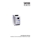
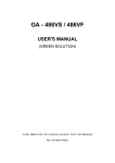
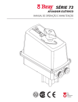
Service Manual for:
S 6
Series 01
WARNING
Man
u
al
International Corporate Hdqrs: P.O. Box 310 Winamac, IN 46996 USA
1-800-THE LIFT ®
(574) 946-6153
FAX: (574) 946-4670
®
®
TM
TM
Braun SL600 Series
"Providing Access to the World"
Read manual
before installing
or servicing lift.
Failure to do so
may result in
serious bodily
injury and/or
property damage.
35973
March
2010
Congratulations
We at The Braun Corporation wish to express our fullest appreciation
on your new purchase. With you in mind, our skilled craftsmen have designed and
assembled the finest lift available.
This manual provides maintenance and service-related material. Braun Vista
Series™ lifts are built for dependability and will provide years of pleasure and independence as long as the lift is properly maintained and operated by an instructed person.
Sincerely,
THE BRAUN CORPORATION
Ralph W. Braun
Chief Executive Officer
Warranty
Consult your local Braun dealer regarding warranty policy.
www.braunlift.com/international
The Braun Corporation
1-800-THE LIFT®
BRAUNLIFT.COM®
MODEL NUMBER
Model No.
XXXXXXXXXX
SERIAL NUMBER
Serial No.
XX-XXXXX
MFG DATE
Date of Manufacture
XX/XX/XXXX
Sample Serial No./Series No. Identification Tag
Serial No.
Model No.
OWNER'S WARRANTY REGISTRATION
XXXXXXXXXX
XX-XXXXX
PURCHASED FROM
OWNER
DATE INSTALLED
NAME
ADDRESS
CITY
TELEPHONE
STATE
ZIP
TO VALIDATE WARRANTY
REGISTRATION CARDS MUST BE RETURNED TO THE BRAUN CORPORATION.
Sample Warranty/Registration Card
Contents
Troubleshooting and Maintenance
Lift Terminology ......................................................... 2-3
Lift Dimensions ............................................................. 4
Operation Notes and Details ........................................ 5
Lift Operating Instructions......................................... 6-7
Manual Operating Instructions..................................... 8
Lubrication Diagram ....................................................10
Maintenance and Lubrication Schedule ............... 11-13
Lift Electrical Schematic ............................................ 14
Lift Wiring Diagram .................................................... 15
Hydraulics
Hydraulic Parts List .................................................... 17
Hydraulic Diagram ...................................................... 18
Hydraulic Schematic .................................................. 19
Repair Parts
Pump Module
Pump Module Parts List ........................................ 20
Pump Module Diagram .......................................... 21
Lift Exploded Views and Parts Lists
Main Body Assembly ............................................. 22
Upright / Platform Assembly ................................. 23
Step Assembly ....................................................... 24
Outer Platform Assembly ...................................... 25
Warranty
Braun® Limited Warranty ....................................... 26-28
Page 1
Lift Terminology
Pump
Module
Hand-Held
Control Pendant
Slide
Tube (2)
®
32819
DOWN
UP
Step
Hand Hold
Mounting
Base
Step Lock
Block (2)
Raise / Lower
Hydraulic
Cylinder (2)
(not visible)
Platform
Upright (2)
Step
(Stowed)
Step Lock
Engagement
Guide (2)
Inner
Platform
Outer
Platform
(Deployed)
Platform
Side Plate (4)
Outer Barrier
Inboard
(
)
Left
Page 2
Right
Outboard
Outer Barrier
Activation Foot
Lift Terminology
Right
Handrail
Left
Handrail
®
32819
DOWN
UP
Hand-Held Control
Pendant Hanger
(Key Hole Slot)
Step
(Deployed)
Platform
Handle
Outer
Platform
(Stowed)
Outer Barrier
Activation Foot
Platform
Side Plate (4)
Inboard
(
)
Left
Right
Outboard
Page 3
Lift Dimensions
160.7 cm
(63 1/4")
51.4 cm
(20 1/4")
30.5 cm
(12")
72.2 cm
30.5 cm
(28 7/16")
(12")
75.6 cm
48.3 cm Max.
(29 3/4")
(19" Max.)
121.6 cm
(47 7/8")
85.1 cm
(33 1/2")
79.4 cm
(31 1/4")
60.6 cm
11.7 cm
(23 7/8")
(4 5/8")
109.9 cm Max.
(43 1/4" Max.)
108.9 cm
(42 7/8")
77.8 cm
(30 5/8")
30.5 cm
(12")
87.6 cm
38.4 cm
(34 1/2")
(15 1/8")
149.9 cm
(59")
83.2 cm
(32 3/4")
96.5 cm
(38")
Page 4
Operation Notes and Details
When the bus door(s) open, the SL600 “Step
Lift” is positioned in the doorway such that the
stowed platform serves as the bottom step (entry). The lift-equipped step is horizontal (serving
as the second step).
Lift Power ON/OFF Switch: This pump modulemounted switch must be in the ON position in
order to activate the lift. A green Power Indicator
Light illuminates to signal power to the lift.
Hand-held Pendant Control: The hand-held
attendant's pendant control is equipped with a
single UP/DOWN rocker switch. The momentary switch activates the power UP and gravity
DOWN functions.
Stow (
)
Two red Stow arrows provided on the right slide
tube must be aligned before manually stowing the
lift (platform and step). Press UP or DOWN to position the lift at stow height (align arrows). Lift and
rotate the outer platform 180° inward to stowed
position (stacked). Manually position the step for
stow as detailed below.
Red Stow Arrows
The SL600 features a 2-stage platform. The
outer platform is manually deployed and stowed.
The lift-equipped step raises automatically as
the lift raises and stows (locks) as the lift lowers. The step is manually positioned for the stow
(lock) function.
Deploy (
Step
positioned
for stow.
)
The lift must be raised to the proper position
(height) to allow manual deployment of the outer
platform. Two green Deploy arrows provided on
the left slide tube must be aligned before deploying the outer platform.
As the lift raises from stow position - the step
rotates to vertical position and latches. Once the
step is latched in the vertical position and green
Deploy arrows are aligned - the outer platform
can be manually deployed. Lift and rotate
platform 180° outward to horizontal position. A
recessed pivoting handle is provided in the outboard platform for manual operation.
If the step is not latched in the vertical position
and the lift is not properly positioned (green
arrows aligned) - hand injury could occur when
manually rotating
the platform.
WARNING
Manually rotating
outer platform when
step is horizontal
and/or green arrows
are not aligned could
result in hand injury.
Once the outer
platform is fully
deployed - the lift
can be lowered
to the ground or
raised to floor
level (as needed).
Step Lock
Bracket
Guides
Once the outer platform
has been stowed, the
step can be manually positioned for stow (lock).
Manually unlatch and
lower (rotate) the step to
a 45° angle. Lock blocks
at each end of the step
align with engagement
guides on yellow step
lock brackets.
The step lock blocks engage and travel the path of the locking engagement
guides as the lift is lowered. When the step reaches
fully stowed position (horizontal) - the step blocks
lock fully in the engagement guides, stopping (locking) the platform at proper position (entry level).
Lift Operating Instructions
Refer to the step-by-step Lift Operating Instructions
provided in this manual and on lift-posted decals.
Refer to the Manual Operating Instructions to manually operate lift. Replace any missing, worn or illegible decals.
Page 5
Lift Operating Instructions
OPEN DOOR(S) AND
SECURE
TO DEPLOY LIFT:
1. Align Green Arrows.
Stand clear and press UP
switch until lift reaches
deploy level (two green
Deploy arrows align).
Note: The step folds (rotates) to vertical position
and latches as lift raises.
2. Deploy Platform
Lift and rotate outer platform to deployed position
using handle.
To Lower Platform
Press DOWN switch until
entire platform reaches
ground level and outer
barrier unfolds fully.
To Raise Platform
Press UP switch until lift
reaches floor level (stops).
Page 6
Lift Operating Instructions
TO STOW LIFT:
1. Align Red Arrows.
Lower lift (press DOWN
switch) or raise lift (press
UP switch) until lift reaches
stow level (two red Stow
arrows align).
2. Stow Platform
Lift and rotate outer platform in to stowed position.
3. Stow Step
Unlatch and lower step
(step lock blocks align with
step lock brackets).
4. Stow Lift
Press DOWN switch to
lower lift fully (stops).
Page 7
Manual Operating Instructions
DOWN (TO LOWER):
UP (TO RAISE):
Using hand pump handle:
Using hand pump handle:
1. Open hand pump valve
(turn counterclockwise). Open 1/4 turn
only.
1. Close hand pump valve
(turn clockwise).
Note: Valve must be
tight, but do not overtighten.
2. Insert handle hand
pump and stroke.
Note: Refer to Lift Operating
Instructions for platform and
step procedures.
Page 8
Note: Close valve securely before operating
electric pump.
NOTES
This page intentionally left blank.
Page 9
Maintenance and Lubrication
Lubrication Diagram
Slide Tube Chain
Main Rollers (2)
LO
Slide Tubes
(Inside - 2)
LO
®
32819
DOWN
UP
Step Lock
Blocks (2)
DE
Step Hinge (2)
LO
Slide Tubes
(Outside - 2)
DE
Slide Tube
Carrier Bearings
(Buttons -16)
Slide Tube
Carrier Rollers (4)
LO
Step Lock
Engagement
Guides (4)
DE
Outer Platform
Fold Bearings
(2)
LO
Outer Barrier
Bracket Slots (2)
LG
Upright
Rollers (10)
LO
Activation Foot
Bearings (2)
LO
Outer Barrier
Pivots (2)
LO
See the Maintenance/Lubrication Schedule for recommended applications per number of cycles.
Lubricant
LO - Light Oil
DE - Door-Ease
LG - Light Grease
Page 10
Type
Specified (recommended)
Lubricant
Light Penetrating Oil
LPS2, General Purpose
(30 weight or equivalent)
Penetrating Oil
Stainless Stick
Door-Ease
Style (tube)
Stick (tube)
Light Grease
Lubriplate
(Multipurpose)
Available
Amount
16 oz.
Aerosol Can
1.68 oz.
14 oz.
Can
Braun
Part No.
15807
15806
15805
Maintenance and Lubrication Schedule
Proper maintenance is necessary to ensure safe,
trouble free operation. Inspecting the lift for any
wear, damage or other abnormal conditions should
be a part of the transit agency daily service program.
Simple inspections can detect potential problems.
The maintenance and lubrication procedures specified in the following schedule must be performed
by a Braun authorized service representative at
the scheduled intervals according to the number of
cycles. All service procedures must be performed
when the lift is fully on the ground.
SL600 Series lifts are equipped with hardened pins
and self-lubricating bushings to decrease wear,
provide smooth operation and extend the service life
of the lift.
When servicing the lift at the recommended intervals,
inspection and lubrication procedures specified in
the previous sections should be repeated. Clean
components and the surrounding area before applying lubricants. LPS2 General Purpose Penetrating
Oil is recommended where Light Oil is called out.
Use of improper lubricants can attract dirt or other
contaminants which could result in wear or damage
to the components. Platform components exposed
to contaminants when lowered to the ground may
require extra attention.
following the scheduled
4500 cycle maintenance
procedures. These
intervals are a general
guideline for scheduling
maintenance procedures
and will vary according
to lift use and conditions.
Lifts exposed to severe
conditions (weather, environment, contamination,
heavy usage, etc.) may
require inspection and
maintenance procedures
to be performed more
often than specified.
WARNING
Maintenance and
lubrication procedures
must be performed as
specified by an
authorized service
technician. Failure to
do so may result in
serious bodily injury
and/or property
damage.
Discontinue lift use immediately if maintenance and
lubrication procedures are not properly performed, or if
there is any sign of wear, damage or improper operation.
Contact your sales representative or call The Braun Corporation. One of our national Product Support representatives will direct you to an authorized service technician
who will inspect your lift.
Lift components requiring grease are lubricated
during assembly procedures. When replacing these
components, be sure to apply grease during installation procedures. Specified lubricants are available
from The Braun Corporation (part numbers provided
on previous page).
All listed inspection, lubrication and maintenance
procedures should be repeated at 750 cycle intervals
750
Cycles
Outer barrier pivots (2)
Apply Light Oil - See Lubrication Diagram
Activation foot bearings (2)
Apply Light Oil - See Lubrication Diagram
Outer barrier bracket slots (2)
Apply Light Grease to both sides of slot on each
bracket. See Lubrication diagram.
Outer platform fold bearings (2)
Apply Light Oil - See Lubrication Diagram
Inspect outer barrier for proper operation,
positive securement, and detached or missing
springs
Correct or replace damaged parts and/or relubricate. See Lubrication Diagram
Inspect lift for wear, damage or any abnormal
condition
Correct as needed.
Inspect lift for rattles
Correct as needed.
Page 11
Maintenance and Lubrication Schedule
Perform all procedures listed in previous section also
1500
Cycles
Step lock blocks (2)
Apply Door Ease - See Lubrication Diagram
Step lock engagement guides (4)
Apply Door Ease - See Lubrication Diagram
Step hinges (2)
Apply Light Oil - See Lubrication Diagram. Use
Light Grease during roller replacement.
Upright rollers (10)
Apply Light Oil - See Lubrication Diagram.
Slide tubes (outside) (2)
Apply Door Ease to where platform upright UHMW
bearings (buttons) contact slide tube. See Lubrication Diagram.
Slide tubes (inside) (2)
Apply Light Oil to inside surface of slide tubes.
See Lubrication Diagram.
Slide tube carrier rollers (4)
Apply Light Oil - See Lubrication Diagram.
Inspect handrail for wear or damage, and for
proper securement
Replace damaged parts.
Make sure lift operates smoothly
Lubricate or correct as needed.
Inspect external snap rings / e-clips:
• Latch foot (2)
• Upright rollers (20)
• Main rollers (2)
Resecure or replace if needed.
Inspect all threaded fasteners for damage and
positive securement.
Resecure or replace damaged fasteners. See Exploded View section for fasteners that require #242
General Purpose Blue Loctite (Braun #18822).
Remove pump module cover and inspect:
• Hydraulic hoses, fittings and connections for
wear or leaks on pump.
• Harness cables, wires, terminals and connections for securement or damage
Resecure, replace or correct as needed.
Perform all procedures listed in previous section also
4500
Cycles
continued
Page 12
Inspect cotter / cottered pins:
• Slide tube chain cottered pins (4)
• Slide tube chain cotter pins (4)
Resecure or replace if needed.
Inspect UHMW bearings (buttons):
• Slide tube carriers (16)
• Platform uprights (4)
Resecure or replace if needed.
Hydraulic Fluid (Pump) - Check level. Note:
Fluid should be changed if there is visible
contamination. Inspect the hydraulic system
(cylinder, hoses, fittings, seals, etc.) for leaks if
fluid level is low.
Use Braun 32840-QT (Exxon® Univis HVI 26). Do
not mix with Dextron III or other hydraulic fluids.
Check fluid level with platform lowered fully. Fill to
maximum fluid level indicated on reservoir (specified on decal). Do not overfill. If fliud level decal
is not present - measure 3/4" from the fill port to
locate fluid level.
Inspect cylinders, fittings and hydraulic connections for wear, damage or leaks
Tighten, repair or replace if needed.
Inspect platform uprights, slide tubes, slide tube
carriers and inboard and outboard platform.
Replace damaged parts and resecure as needed.
Maintenance and Lubrication Schedule
continued
4500
Cycles
Inspect slide tube chain main rollers (2)
Apply light oil or replace as needed. See Lubrication Diagram.
Inspect power cables
Resecure, repair or replace if needed.
Mounting
Check to see that the lift is securely anchored to
the vehicle and there are no loose bolts, broken
welds, or stress fractures.
Decals
Replace decals if worn, missing or illegible.
Inspect slide tube chains for stretch or damage.
Check chain tension at floor level. Both sides must
be equal. Adjust using threaded chain bolt located
inside slide tube. Replace if needed.
Inspect chain bolt for proper securement, chain
attachment or damage.
Verify bolt is securely tightened and is aligned so
that chain does not twist. Replace if needed.
Consecutive Repeat all previously listed inspection, lubrica750 Cycle tion and maintenance procedures at 750 cycle
intervals.
Intervals
Page 13
Lift Electrical Schematic
SWITCH BOX
OR(22)
UP
DESCRIPTION
SYMBOL
BK(22)
DOWN
LED LIGHT
+
-
WH(22)
BATTERY
CHASSIS GROUND
CIRCUIT BREAKER/FUSE
JUNCTION
OR(22)
BK(22)
1
2
3
4
WH(18)
1
2
3
4
CONNECTER
OR(18)
RD(18)
SWITCH
5
3
4
8
7
9
1
6
2
1
6
2
5
3
4
8
7
9
SOLENOID
WH(22)
M
MOTOR
NOTES:
1) JUNCTIONS ONLY OCCUR AT
MARKED INTERSECTIONS.
POWER / INTERLOCK
LED
OR(18)
RD(18)
GN(18)
DOWN
SOLENOID
PUMP
GROUND
(N.C. Valve)
RD(18)
RD(18)
UP/FOLD
SOLENOID
GN(18)
M
OR(18)
RD(18)
PUMP
BK(6)
LIFT
POWER
SWITCH
PUMP
GROUND
RD(18)
RD(4)
OFF
HYDRAULIC
CIRCUIT
SENTRY
(UP)
(CIRCUIT BREAKER)
CHASSIS
GROUND
RD(4)
RD(2)
CHASSIS
GROUND
WH(18)
Page 14
ON
WH(18)
GN(18)
WH(18)
RD(18)
-
WH(18)
+
Lift Wiring Diagram
Hand Pendant
(As Viewed From Terminal
Side of Switches)
BK(22)
Up/Down
Switch
OR(22)
OR(22)
7-COND WIRE CODE
NO.
COLOR
1
NOT USED
2
ORANGE(22) - UP
3
NOT USED
NOT USED
4
6
NOT USED
WHITE(22) - POSITIVE +
2
5
5
1 2
3 4 5
6 7
2
4
6
2 1
5 4 3
7 6
6
1
3
3
1
4
7
7
35895A
BLACK(22) - DOWN
5
7
7-COND WIRE CODE
NO.
COLOR
1
NOT USED
2
ORANGE(18)
3
NOT USED
4
NOT USED
RED(18)
6
NOT USED
WHITE(18)
35892A
5
7
OR(18)
RD(18)
WH(18)
Power / Interlock
LED
Lift Power
Switch
RD(18)
+ -
RD(18)
WH(18)
WH(18)
WH(18)
Up/Fold
GN(18)
BK(6)
Hydraulic
Pump
35896A
35897A
29049
Solenoid
BK(6)
RD(4)
RD(18)
RD(18)
GN(18)
OR(18)
GN(18)
B
A
T
A
U
X
Lift
Power Cable
#33688A
Connects to
Vehicle Battery
(+) Positive Post
GN(18)
RD(18)
Lead Wire
13362A
GN(18)
Circuit Sentry
(Circuit Breaker)
Bat.
RD(18)
Ground
Down
Solenoid
RD(2)
Aux.
Page 15
NOTES
This page intentionally left blank.
Page 16
Hydraulic Schematic
Unfold Orifice
Unfold Orifice
OPPOSITE
PUMP
CYLINDER
Description
BACK-UP
PUMP
PUMP
PUMP SIDE
CYLINDER
Symbol
Description
Fixed Displacement
Pump
Manual Shut
Off Valve
Vented Reservoir
Unfold Orifice
Lever
Solenoid Actuated
2 Way Normally Closed Valve
Single Acting Cylinder
Check Valve
Symbol
Relief Valve
Filter
Hydraulic Port
Page 17
Hydraulics Parts List
Item Qty.
Description
Part #
1
1
Pump Assembly (M3219-0115) 12V - w/Reservoir and Backup Pump
35702-12V
2
1
Clamp, Hose (M268)
29663
3
1
Solenoid, 4 - Post Trombetta - Angle
35310
4
1
Motor, Pump - 12V - Low RPM
29690
5
1
Valve Assembly, “Down” (complete) -- Includes items 6 & 7
35080
6
1
Coil (only), Valve - (shown below)
35079
7
1
Cartridge (only), “Down” Valve - (shown below)
31124
8
1
Clamp, Reservoir - H-48 (M259)
17069
9
1
Reservoir, Hydraulic Fluid
30160
10
3
Screw, 1/4-20 x 2-1/4", Allen Head
26080
11
1
Hand Pump (Backup) with O-Rings (Item 12)
31125
12
2
O-Ring (only), Hand Pump Mounting
17351
13
1
Cap, Reservoir Filler - Screw On
30167
14
1
Fitting, Male 7/16-20 SAE O-Ring to 7/16-20 JIC 37° Male
24504
15
1
Elbow, Manifold - 7/16-20 JIC 37 Female Swivel x 7/16-20 JIC 37° Male (2)
26579
16
1
Hose Assembly, 3/16" (Pump-Side)
915-5603-63.5
17
1
Hose Assembly, 3/16" (Opposite-Pump-Side)
915-5603-108
18
2
Cylinder (includes item 19)
C1522-2404SLA
19
2
Elbow, 90°, 3/8-24 SAE O-Ring Male - 7/16-20 JIC 37° Male - Orifce
20
1
Handle with Grip
35834
17206A
Seal Kits: If repairing a cylinder, order Seal Kit #1500-0500P.
5
“Down” Valve
(complete)
6
Coil
#35079
7
Cartridge
#31124
Page 18
Hydraulics Diagram
1
18
18
2
3
20
19
Hydraulic
Pump Motor
19
4
13
Manual
Back-up
Pump
Hydraulic
Pump
5
12
11
20
14
10
8
16
9
Pump Side Cylinder
Opposite Pump Cylinder
15
17
Page 19
Pump Module Parts List
Item Qty.
Description
Part #
1
Pump Module (Contains 1-14 & 16-21)
SL05-001A
1
1
Weldment, Pump Mount
SL05-001W
2
1
Pump, M259 w/Monarch Reservior - 12V
35702-12V
3
1
Cover, Pump
SL001-018
4
1
Screw, T-Head Thumb 10-32 x 3/8”
33435
5
4
Pop Rivet, 3/16” x .13”/.25” - SD64BS - Black
11513
6
2
Spring Clamp, Pump Handle
12350
7
1
Pump Handle with Grip
8
2
Washer, 5/16” External Tooth
16368
9
2
Bolt, 5/16-18 x 3/4” w/Nylock Patch ◆
29608
10
1
Diode, Green LED - Panel Mount
29545
11
1
Switch, Toggle w/Gold Contacts
31787
12
1
Fitting, 7/16-20 Male SAE O-Ring x 7/16-20 JIC 37° Male
24504
13
1
Elbow, Manifold - 7/16-20 JIC 37° Female Swivel x 7/16-20 JIC 37° Male (2)
26579
14
4
Snap Rivet, Nylon, .124” Hole x .197”-.236” Thick
29874
15
1
Hand Pendant ✘
35895A
16
1
Harness, Battery #4GA SGX - 3/8” Eye - 37’ w/Loom ✔
33688A
17
1
Harness, Main - SL600 ✔
35892A
18
1
Harness, Ground - SL600 ✔
35896A
19
1
Harness, Power - SL600 ✔
35897A
20
1
Hose Assembly, 3/16” Diameter x 108” ✔
915-5603-108
21
1
Hose Assembly, 3/16” Diameter x 63.5” ✔
915-5603-63.5
17206A
(◆) Apply red #271 Thread Locker Loctite® to the two pump mounting bolts (item 9) if a blue nylon patch is not present
on the bolts when retrofitting an M259 pump assembly. Loctite® is available from The Braun Corporation under part
number 11522-1.
(✘) Indicates items not included with replacement pump modules (complete).
(✔) Indicates items not shown.
Page 20
Pump Module Diagram
4
7
3
5
5
6
15
®
32819
DO
WN
UP
9
10
14
8
1
12
13
11
Pump Mounting Bolts
2
Apply red #271 Thread Locker Locktite® to the two
pump mounting bolts (item 9) if a blue nylon patch
is not present on the bolts when retrofitting an M259
pump assembly. Loctite® is available from The
Braun Corporation under part number 11522-1.
Page 21
Exploded Views and Parts Lists
Main Body Assembly
16
5
10
8
12
4
17
7
6
8
9
4
10
3
12
2
13
1
11
14
15
3
* - ITEMS NOT SHOWN
Page 22
19
4
23173*
18
2
21708R058*
CHAIN-LEAF-4X4-.5 PITCH X 58"
17
1
35380FA
ASSEMBLY-SLIDE TUBE-CARRIER
16
1
35380RA
ASSEMBLY-SLIDE TUBE-CARRIER
15
8
10084
SCREW-#8-18 X 1" SELF-TAP HEX
14
4
800-3003
CLAMP, CYLINDER (L800 & L205)
13
2
C1522-2404SLA
CYL. ASSY-STEPLIFT
12
18
13583
SCREW-#8-18 X 1/2" PH/PN SD-AUTO-BK
COVER-CHAIN CHANNEL
PIN-COTTER 1/32 X 1/2 (4X4)
11
2
SL01-016
10
4
84189
RING-RETAINING 5/8
9
4
21759
PIN-COTTERED-466 CHAIN-TSUBAKI
8
7
2
2
14414
NUT-7/16-14 HEX JAM/AUTO-BK
6
2
21711
BOLT-CHAIN:4X4:7/16-14-3.046
12895
NUT-7/16-14 HEX NYLOCK
5
2
35362
ROLLER-MAIN
4
2
35359
PIN - MAIN ROLLER
3
6
11513
RIV-POP-SD64BS-3/16"-.13/.25/AUTO-BK
2
1
SL01-020Y
STEP STOP
1
1
SL01-001W
WMT-BACK PLATE
ITEM
QTY
PART NUMBER
DESCRIPTION
Exploded Views and Parts Lists
Upright / Platform Assembly
11
8
4
3
13
12
3
7
2
10
5
9
1
6
13
1
SL03-003FWY
WMT-BKT-STEP LOCK/FRONT
12
1
SL03-003RWY
WMT-BKT-STEP LOCK/REAR
11
3
11513
RIV-POP-SD64BS-3/16"-.13/.25/AUTO-BK
10
6
82033R001
TAPE 1/16 X 3/4 X 108 DBL FACE x 1"
9
4
82033R023.5
TAPE 1/16 X 3/4 X 108 DBL FACE x 23 1/2"
8
1
SL04-004DS
PLATFORM SKIN-INNER
7
6
35361
ROLLER-UPRIGHT
6
12
84383
E CLIP-3/8 SHAFT
5
6
35570
PIN-CARRIER ROLLER
4
4
205-1760
BEARING-UHMW FLAT/1.226-THN-BLK
3
12
25171
BOLT-5/16-18 X 2" FLBHSCS-GD8
2
2
SL06-001WY
WMT-HANDRAIL
1
1
SL03-001W
WMT-PLATFORM
ITEM
QTY
PART NUMBER
DESCRIPTION
Page 23
Exploded Views and Parts Lists
Step Assembly
2
4
9
3
5
8
6
1
Assembled View
9
4
8
7
3
11513
2
35726
STEP HINGE PIN
6
4
35714A
ASSY-BLK-HINGE
SCREW- 3/8-16 x 1-1/4 BHCS
82033R011.5
7
TAPE 1/16 X 3/4 X 108 DBL FACE x 11 1/2"
RIV-POP-SD64BS-3/16"-.13/.25/AUTO-BK
5
4
35777
4
3
14993
RIV-POP-SD66BS-3/16"-.25/.38/AUTO-BK
3
1
SL01-021Y
STEP COVER
2
1
SL01-012
STEP SKIN
1
1
SL01-008W
WMT-STEP
ITEM
QTY
PART NUMBER
DESCRIPTION
Outer Platform Assembly Parts List
(See Illustration at Right)
14
13
1
1
SL04-011Y
SL04-012R
ROLLSTOP-STEP LIFT
ROLL STOP - REAR
12
1
SL04-012F
11
28
1
28132R
ROD-5/32" TORSION SPRING BAR - REAR
ROLL STOP - FRONT
27
26
1
4
28132F
14614
ROD-5/32" TORSION SPRING BAR - FRONT
NUT-1/4-20 NYLOCK/AUTO-BK
2
28128
BEARING-FLANGE-10MM X 12MM-BB1012DU
25
2
945-0336N
10
1
35766
HANDLE-PLATFORM UNFOLD-STEPLIFT
24
RING-1/2 EXT SELF LOCK SNAP/AUTO-BK
8
14549
SCREW-#8-18 X 1" WH SELF TAP/AUTO-BK
23
2
4
13889
9
29371
WASHER-THRUST-.875 OD/.50 ID/.0585T
8
7
1
SL04-009B
OUTER PLATFORM SKIN-BOTTOM
22
1
SL04-015
GROUND FOOT-SAC PAD
4
82033R023.5
TAPE 1/16 X 3/4 X 108 DBL FACE x 23 1/2
21
1
SL04-014FW
WMT-LATCH FOOT-FRONT
6
1
20
1
SL04-014RW
WMT-LATCH FOOT-REAR
2
SL04-010Y
24442
OUTER PLATFORM-TRIM
5
BEARING-FLANGE-1/2" X 1/4"-08FDU04
19
2
10064
WASHER-3/8" FLAT/AUTO-BK
4
17
11513
RIV-POP-SD64BS-3/16"-.13/.25/AUTO-BK
18
2
11563
SCREW-1/4-20 X 1/4 SET CUP PT
3
1
SL04-009TDS
OUTER PLATFORM SKIN-TOP
17
4
18349
NUT-#10-32 W/LOCKWASHER/AUTO-BK
2
4
82033R025.5
TAPE 1/16 X 3/4 X 108 DBL FACE x 25 1/2
16
4
17192P
SCREW-#10-32X1/2 FHDHXS-AUTO BLK-W/PATCH
1
1
SL04-005W
WMT/OUTER PLATFORM
15
2
28131
PIN-CLEVIS-5/16 X 1.032" LEN-AUTO BLACK
ITEM
QTY
ITEM
QTY
Page 24
PART NUMBER
DESCRIPTION
PART NUMBER
BEARING-PLATFORM SLIDE
DESCRIPTION
Exploded Views and Parts Lists
Outer Platform Assembly
(See Parts List on Lower Left)
3
4
2
15
13
24
28
23
25
23
11
20
14
19
17
18
5
1
16
26
27
19
4
12
6
7
21
15
22
23
8
25
24
23
9
10
4
Page 25
Braun® Limited Warranty
WARRANTY COVERAGE AND WARRANTY COVERAGE TIME PERIODS
The Braun Corporation (“Braun”) warranty covers certain parts of this wheelchair lift for three (3) years or
7500 cycles and the cost of labor to repair or replace those parts for one (1) year or 2500 cycles . This
limited warranty covers substantial defects in materials and workmanship of the lift, provided that the lift is
operated and maintained properly and in conformity with the owner’s manual. The warranty period begins
on the date that the product is delivered to the first retail purchaser by an independent, authorized dealer
of Braun, or, if the dealer places the product into any type of service prior to retail sale, on the date the
dealer first places the product in such service. This limited warranty applies only to the first purchaser. It
may not be transferred.
WHAT BRAUN WILL DO TO CORRECT PROBLEMS
In the event that a substantial defect in material or workmanship, attributable to Braun, is found to exist
during the first year of warranty coverage, it will be repaired or replaced, at Braun’s option, without charge
for parts or labor to the owner, in accordance with the terms, conditions and limitations of this limited warranty. If the substantial defect in material or workmanship, attributable to Braun, is found to exist during
the second or third year of warranty coverage, it will be repaired or replaced, at Braun’s option, without
charge to the owner for parts, only, in accordance with the terms, conditions and limitations of this limited
warranty. The cost of labor for any repair or replacement in the second and third year of warranty coverage is the sole responsibility of the owner. This warranty does not cover labor costs in the second or third
year of coverage.
Braun’s obligation to repair or replace defective materials or workmanship is the sole obligation of Braun
under this limited warranty. Braun reserves the right to use new or remanufactured parts of similar quality
to complete any work, and to make parts and design changes from time to time without notice to anyone.
Braun reserves the right to make changes in the design or material of its products without incurring any
obligation to incorporate such changes in any previously manufactured product. Braun makes no warranty as to the future performance of this product, and this limited warranty is not intended to extend to
the future performance of the product. In addition, the owner’s obligation to notify Braun, or one of its
authorized, independent dealers, of a claimed defect does not modify any obligation placed on the owner
to contact Braun directly when attempting to pursue remedies under state or federal law.
LIMITATIONS, EXCLUSIONS AND DISCLAIMER OF IMPLIED WARRANTIES
ANY IMPLIED WARRANTY THAT IS FOUND TO ARISE BY WAY OF STATE OR FEDERAL LAW,
INCLUDING ANY IMPLIED WARRANTY OF MERCHANTABILITY OR ANY IMPLIED WARRANTY OF
FITNESS, IS LIMITED IN DURATION TO THE TERMS OF THIS LIMITED WARRANTY AND IS LIMITED IN SCOPE OF COVERAGE TO THE SCOPE OF COVERAGE OF THIS LIMITED WARRANTY.
Braun disclaims any express or implied warranty, including any implied warranty of fitness or merchantability, on items excluded from coverage as set forth in this limited warranty. Braun makes no warranty
of any nature beyond that contained in this limited warranty. No one has authority to enlarge, amend or
modify this limited warranty, and Braun does not authorize anyone to create any other obligation for it
regarding this product. Braun is not responsible for any representation, promise or warranty made by any
independent dealer or other person beyond what is expressly stated in this limited warranty. Any selling
or servicing dealer is not Braun’s agent, but an independent entity.
BRAUN SHALL NOT BE LIABLE FOR ANY INCIDENTAL OR CONSEQUENTIAL DAMAGES THAT
MAY RESULT FROM BREACH OF THIS LIMITED WARRANTY OR ANY IMPLIED WARRANTY. THIS
EXCLUSION OF CONSEQUENTIAL AND INCIDENTAL DAMAGES SHALL BE INDEPENDENT OF
ANY FAILURE OF THE ESSENTIAL PURPOSE OF ANY WARRANTY, AND THIS EXCLUSION SHALL
SURVIVE ANY DETERMINATION THAT THIS LIMITED WARRANTY OR ANY IMPLIED WARRANTY
HAS FAILED OF ITS ESSENTIAL PURPOSE. This warranty does not cover, and in no event shall Braun
be liable for towing charges, travel, lodging, or any other expense incurred due to the loss of use of the
product or other reason.
Page 26
Braun® Limited Warranty
Some states do not allow limitations on how long an implied warranty lasts, or the exclusion or limitation of
incidental or consequential damages, so the above limitations or exclusions may not apply to you.
HOW TO GET SERVICE
To obtain warranty service the owner must do all of the following:
1. Notify an authorized service center, of the claimed defect attributable to Braun, within the warranty coverage period designated above.
2. Provide the notification mentioned in (1), above, within ten (10) days of when the owner discovered, or
should have discovered, the claimed defect.
3. Promptly schedule an appointment with and take the product to an authorized service center for service.
4. Pay any transportation costs and all expenses associated with obtaining warranty service.
Since Braun does not control the scheduling of service work at the independent dealerships you may encounter some delay in scheduling or completion of work. If you need assistance you may contact Braun, at
631 West 11th Street, Winamac, Indiana 46996; 1-800-THE-LIFT, (843-5438).
If two (2) or more service attempts have been made to correct any covered defect that you believe impairs
the value, use or safety of the product, or if it has taken longer than thirty (30) days for repairs to be completed, you must, to the extent permitted by law, notify Braun directly, in writing, at the above address, of
the unsuccessful repair(s) of the alleged defect(s) so that Braun can become directly involved in providing
service pursuant to the terms of this limited warranty.
WHAT IS NOT COVERED
This Limited Warranty does not cover any of the following: defects in materials, components or parts of
the product not attributable to Braun, any material, component or part of the product that is warranted by
another entity (Note: the written warranty provided by the manufacturer of the material, component or part
is the direct responsibility of that manufacturer); items that are added or changed after the product leaves
Braun’s possession; additional items installed at any dealership, or other place of business, or by any other
party, other than Braun; normal wear, tear, usage, maintenance, service, periodic adjustments, the effects
of condensation or moisture from condensation; mold or any damage caused by mold; imperfections that do
not affect the product for its intended purpose; items that are working as designed but that you are unhappy
with; problems related to misuse, mishandling, neglect or abuse, including failure to maintain the product in
accordance with the owner’s manual, or other routine maintenance such as inspections, lubricating, adjustments, tightening of screws, sealing, wheel alignments or rotating tires; damage due to accident or collision, including any acts of weather or damage or corrosion due to the environment; theft, vandalism, fire,
or other intervening acts not attributable to Braun; damage resulting from tire wear or tire failure; defacing,
scratches, dents or chips on any interior or exterior surface of the product, including those caused by rocks
or other road hazards, damage caused by off road use, overloading or alteration of the product, or any of its
components or parts.
Defects and/or damage to interior and exterior surfaces and other appearance items may occur at the factory or when the product is in transit. These items are usually detected and corrected at the factory or by
a dealer prior to delivery to the purchaser. You must inspect the product for this type of damage when you
take delivery. If you find any such defect or damage you must notify the selling dealer, or Braun, at the time
of delivery to have these items covered by this limited warranty and to have work performed on the items at
no cost to you as provided by this limited warranty.
Page 27
Braun® Limited Warranty
EVENTS DISCHARGING BRAUN FROM OBLIGATION UNDER WARRANTY
The following shall completely discharge Braun from any express or implied warranty obligation to repair
or replace anything and void this warranty: misuse, neglect, collision, accidents, failure to provide routine
maintenance (See Owner’s Manual), unauthorized alteration, off road use, Acts of Nature, damage from
weather or the environment, theft, vandalism, tampering, fire, explosions, overloading the product and
odometer tampering.
LEGAL REMEDIES
Any action to enforce any portion of this limited warranty, or any implied warranty, must be commenced
within six (6) months after expiration of the warranty coverage period designated above or the action will be
barred because of the passage of time. Any performance of repairs shall not suspend this limitation period
from expiring. Any performance of repairs after the warranty coverage period has expired, or performance
of repairs regarding any thing excluded from coverage under this limited warranty shall be considered “good
will” repairs, and they will not alter the terms of this limited warranty, or extend the warranty coverage period
or the filing limitation period in this paragraph. In addition, since it is reasonable to expect that the product
will need some service during the warranty period, this warranty does not extend to future performance. It
only sets forth what Braun will do and does not guarantee anything about the product for any time period.
Nothing in this warranty, or any action of Braun, or any agent of Braun, shall be interpreted as an extension
of any warranty period or the filing limitation period in this paragraph. Some states do not allow a reduction
in the statute of limitations, so this reduction may not apply to you.
WARRANTY REGISTRATION and MISCELLANEOUS
Your warranty registration records should be completed and delivered to the appropriate companies, including the Braun Delivery Checklist & Warranty form. That form must be returned to Braun within twenty (20)
days of purchase. The Braun warranty will not be registered unless this warranty registration is completed
and received by Braun. Failure to file this warranty registration with Braun will not affect your rights under
this limited warranty as long as you can present proof of purchase, but it can cause delays in obtaining the
benefits of this limited warranty, and it changes the start date of the warranty to the date of final assembly of
the product by Braun.
Braun agrees to repair or replace any of its factory installed parts found to have substantial defects within
the appropriate warranty period designated above, provided that the repair is authorized by Braun and carried out by an authorized service center (a Braun labor schedule determines the cost allowance for repairs).
Braun will not honor any warranty claim for repairs or replacement of parts unless the claim is submitted
with the appropriate paperwork, and the work is completed by an independent, factory authorized service
center. The appropriate paperwork can be obtained by written or phone contact with Braun at the contact
information in this warranty.
Braun reserves the right to designate where any warranty work can be performed. Braun also reserves
the right to examine any defective workmanship or part prior to giving any authorization for warranty work.
Braun’s return authorization procedure must be adhered to in order to process any warranty claims.
THIS WARRANTY GIVES YOU SPECIFIC LEGAL RIGHTS. YOU MAY ALSO HAVE OTHER RIGHTS
THAT VARY FROM STATE TO STATE.
Page 28
"Providing Access to the World"
®
Over 300 Braun
Dealers Worldwide
®
"Providing Access to the World"
International Corporate Hdqrs: P.O. Box 310
1-800-THE LIFT®
(574) 946-6153
Winamac, IN 46996 USA
FAX: (574) 946-4670
Service Manual for:
Series 01
Braun SL600 Series
S 6
"Providing Access to the World"
35973
March 2010
®
®
International Corporate Hdqrs: P.O. Box 310 Winamac, IN 46996 USA
1-800-THE LIFT ®
(574) 946-6153
FAX: (574) 946-4670
TM
TM
All illustrations, descriptions and specifications in this manual are based on the latest product information available
at the time of publication. The Braun Corporation reserves the right to make changes at any time without notice.
© The Braun Corporation