1
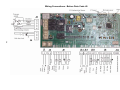
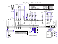
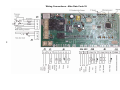
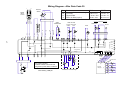
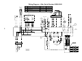
Wiring Diagram - After Date Code 39
N
L
Pressure
Switch
Pins
5-6
3-4
3-7
1-2
16
11
MAINS
INPUT
FILTER
1
14
12
2
1
3
1
3
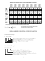
Resistances
Armature Varies with brush-gear
Full Field
Tapped Field
Tacho 16 Pole (8 pairs)
FHP
CESET
1.5 Ω ± 8%
1.78 Ω ± 7%
1.26 Ω ± 8%
1.25 Ω ± 7%
0.47 Ω ± 10% 0.41 Ω ± 7%
135 Ω ± 10%
68.7 Ω ± 7%
4
MOTOR
1
2
WASH VALVES
WASH
THERMISTOR
R
ARMATURE
Pre-Wash Main Wash
COLD
FABRIC
R
R
PUMP
4
1
NC
j1
2
2
5
6
4
7
3
2 1
7
6
5
4
3
2 1
j9
2
1
12 11
j5
L
9
7
j3
6
4
1
3
1A
10A
2
2
Lav.
1
2
*
3
2
1
P
10w
EVL
3
1
10w
EVP
4
1A
OVERFLOW
5
COMMON
10A
FULL
8A
10A
6
EMPTY
2
RR
10A
12A
12A
1
GND
RX
2
T
M
1
1
TACHO
5
1
1
2
j8
9
8
j7
1
SDA
TEST CONNECTOR
17
j15
GND
5
4
3
2
1
5
4
3
2
1
SCL
Vcc
Test
5
RTN_PORTA
RTN_IP
j2
7
2
1
Note: COLD VALVES
Pre-Wash & Wash Valves are both
energised to provide fabric conditioner.
5407170wd2_coldfill.pdf
4
1
A
2
3
4
Connector TAB
5
3
j15
3
2
3
R D CL A cc
VN GN S SD V
Asc.
PCB with
LED lights
Condenser Tumble Dryer
3
2
3
j11
1
3
4
1
j14 2
8
1
1
5
6
j17
4
4
4
j12
1
5
3
3
2
6
2
2
10w
1
1
1
D
C
10A
j13
j10
48w
j4
3
Í
1
3
Í
1
3
Í
1
3
1
M1
3
1
M2
3
1
M3