1
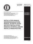
OPERATION
AND SERVICE MANUAL
SERIE "HC"
serie LC e HC
Guarantee and service information
Phone numbers:
Customer service
Assistance for use of chiller
Technical assistance - spare parts
Fax
E-mail
Web site
+39.0438.5844
+39.0438.5844
+39.0438.584271
+39.0438.5843
[email protected]
www.irinox.com
For any request concerning your chiller, always provide the
model and the serial number shown on the following dataplate:
Dear customer,
We wish to thank you for the trust you have shown us by choosing an IRINOX chiller, and we ask you to carefully read the
manual which will provide you with all the necessary information to immediately start chilling your products.
We do in any case suggest that you study this manual so as to take advantage of all the potential and benefits that your
IRINOX chiller has to offer.
Proper operation of the machine also depends on its proper use.
Keep this manual near your chiller, so that it can easily be consulted by you and your operators.
Good work with IRINOX!
Subscribe online to Club Irinox : www.irinox.com
The graphic representation of the commands in this manual makes it easier to understand the operations to be performed,
so that you can immediately start satisfactorily using your IRINOX LOGIK CHILL chiller.
Symbols legend
suggestions and details for correct use of the chiller
instructions for your safety
additional information in this manual
Algemene instructies
1.1 Introductie
De plaatsing mag uitsluitend door geautoriseerde
specialisten worden uitgevoerd met inachtneming van
de instructies in deze handleiding.
Indien de machine wordt uitgerust met een separate
condensor unit is het aansluiten en in werking stellen
van de machine de verantwoording van de
installateur.
Het garantie certificaat welke u in de documentatie
vindt moet gelezen, ingevuld en ondertekend worden
door de installateur en klant en worden teruggestuurd
aan de fabrikant anders zal deze als ongeldig worden
beschouwd.
1.2Veiligheids instructies
Om onderhoud en schoonmaak veilig uit te kunnen
voeren dienen de volgende veilheids instructies in
acht te worden genomen:
•
raak de machine niet met natte of vochtige
handen of voeten aan
•
werk niet blootsvoets aan de machine
•
stop geen gereedschap, keukengerei of andere
voorwerpen tussen de roosters of bewegende
onderdelen
•
sluit
voor
schoonmaak
of
onderhoudswerkzaamheden de machine af van
de voeding door de machine uit te zetten en de
stekker uit het contact te halen
•
trek niet aan de voedingsdraad om de stekker uit
het contact te verwijderen
1.2.1 Beveiliging voor het laden
leegmaken van de machine
en
Beladen:
Gebruik bij het beladen van de machine
ovenwanten om verbranding aan hete potten
en pannen te voorkomen
Leeg maken:
•
Open de deur voorzichtig na afloop van een
koel of vriescyclus tot de ventilator stil staat
•
Verwijder de kerntemperatuurmeter uit het
product en plaats hem in de houder
•
Gebruik passende handschoenen voor koude
pannen en schalen
1.2.2 Pas op voor scherpe kernvoeler
Gebruik van de voeler is uitsluitend toegestaan voor
personeel dat voor het gebruik van de chiller is
geschoold.
De voeler mag alleen gebruikt worden voor het doel
waarvoor het is ontworpen: meting van temperaturen
in de kern van producten die moeten worden gekoeld
of ingevroren.
Ben voorzichtig met de voeler, de punt is scherp om
deze makkelijker in het product te stoppen.
De ergonomische greep maakt het eenvoudig de
voeler te plaatsen of te verwijderen.
1.2.3 Let op de verwarmde kernvoeler
Gebruik de voelerverwarming uitsluitend wanneer
deze in een bevroren product is geplaatst.
Raak om gevaar voor verbranding te voorkomen de
voeler punt niet aan na gebruik van de
verwarmingsfunctie.
1.2.4 Gebruik van de UV-lamp
De sterilisatiefunctie met UV lampen(optioneel) mag
alleen worden gebruikt voor de reden waarvoor deze
is ontworpen: sterilisatie van de wanden van de
koelkamer.
Langdurige blootstelling aan de brandende UV
lampen kan oogirritatie veroorzaken.
1.2.5 Periodieke personeelstraining
Instrueer alle medewerkers die met de machine
werken regelmatig ivm de veiligheidsmaatregelen.
Wijs uw medewerkers op deze handleiding en bewaar
hem op een voor iedereen bekende plaats in de buurt
van de machine om ongelukken te voorkomen.
1.3 Beladen van de machine
Voorkom dat schalen of pannen met deksels of folie
worden afgedekt. Hoe meer oppervlak van het
product in contact komt met de koude lucht hoe
sneller het product afkoelt.
Gebruik zo ondiep mogelijke pannen en schalen, in
ieder geval niet dieper als 6,5 cm.
Voor het beste resultaat raden wij aan de schalen te
vullen met maximaal 3,5 kg product met een
maximale dikte van 8 cm voor koelen of cm voor
vriezen. Gebruik voor moeilijke of vette producten
zelfs dunnere lagen.
Let erop dat er genoeg ruimte tussen de schalen is
zodat genoeg lucht tussen de schalen kan circuleren.
Spreidt wanneer de machine niet volledig wordt
beladen de schalen over de gehele koelkamer.
Plaats de schalen in het midden van de kamer en zorg
ervoor dat deze midden voor de ventilator staan.
Plaats bij trolley gebruik de trolley midden in de
koelruimte.
Belaad de machine niet boven de grenzen aangegeven
door de fabrikant.
1.3.1 Voorkoelen
Het is belangrijk de machine bij een koel of
vriescyclus voor te koelen om de koeltijd te
verkorten. Start daarvoor een Hard of Soft chill cyclus
in de manuele stand voordat de machine wordt
beladen.
Om schade aan de machine te voorkomen
mogen geen warme producten in de
machine blijven staan. Start een koel- of
vriescyclus direct nadat het warme product
in de machine is geplaatst.
1.3.2 Kerntemperatuurmeter (voeler)
De voeler dient goed in het midden van het product te
worden gestoken, zorg ervoor dat de punt niet
uitsteekt of de schaal raakt.
Om ongewenste besmetting te voorkomen moet de
voelerpunt voor ieder cyclus goed worden gereinigd.
Voor het beste resultaat raden wij aan de schalen te
vullen met maximaal 3,5 kg product met een
maximale dikte van 8 cm voor koelen of 5 cm voor
vriezen. Gebruik voor moeilijke of vette producten
zelfs dunnere lagen.
1.3.3 Temperaturen
Vermijdt om producten die moeten worden gekoeld
of
ingevroren
voor
langere
periode
bij
kamertemperatuur te laten staan.
Hoe meer vocht verloren gaat hoe meer schade het
product ondervindt.
Het is aan te raden de producten die gekoeld of
ingevroren moeten worden direct na de bereiding
terug te koelen, bij voorkeur met een temperatuur
boven +70C. Bereide producten kunnen zelfs met een
zeer hoge temperatuur (>100C) direct in de
voorgekoelde chiller worden geplaatst. Houdt er
echter rekening mee dat de referentietijd begint bij
+90C (van +90C tot +3C bij snelkoeling; van +90C
tot -18C bij invriezen).
1.3.4 Conservering
Gekoeld en ingevroren moet goed worden afgedekt en
beschermd (met folie, deksel of door vakuum) en
worden voorzien van een label met vermelding van de
inhoud,
productiedatum
en
vermoedelijke
houdbaarheidsdatum.
Teruggekoeld voedsel moet worden bewaard
in een gekoelde ruimte met een konstante
temperatuur van +2C.
Ingevroren voedsel moet worden bewaard in
een gekoelde ruimte met een konstante
temperatuur van -20C.
Gebruik de chiller niet als bewaar koel- of
vrieskast.
2.Omschrijving van de
controlepanelen
A=
B=
C=
D=
E=
F=
G=
H=
I=
L=
M=
N=
O=
P=
Q=
R=
Aan/uit schakelaar
SOFT chill cyclus keuzeknop
HARD cyclus keuzeknop
Snelvries cyclus keuzeknop
Automatische
cyclus
(kerntemperatuur
gestuurd)
Handmatige cyclus (tijd gestuurd)
Cyclus start/stop knop
Luchttemperatuur uitlezing
Tijd en kerntemperatuur uitlezing
Knoppen voor het handmatig bewerken van de
tijdinstelling
Tijdweergave
Kerntemperatuurweergave
Ontdooi knop
Sterilisatie cyclus knop (UV)
Voeler verwarming
Printen van cycli uit het geheugen
2.1 Omschrijving van de koelprogramma’s
*”SOFT”chilling
Dit programma zorgt voor een snelle terugkoeling tot
+3C waarbij de koeltemperatuur schommelt tussen
0C en +2C (in ieder geval nooit onder 0C) binnen 90
minuten.
Deze cyclus is bijzonder geschikt voor delicate
producten zoals; mousses, puddings, cremes, deserts,
groentes en etenswaren van geringe dikte.
*”HARD”chilling
Dit programma zorgt voor een snelle terugkoeling tot
+3C waarbij de koeltemperatuur schommelt tussen 15C en +2C.
Deze cyclus zorgt voor een aanzienlijk verkorte
terugkoeltijd en is zeer geschikt voor producten met
een hoog vetgehalte, hoge dichtheid, grote stukken of
verpakte producten.
*SHOCK FREEZING
Met deze cyclus wordt de kerntemperatuur tot -18C
teruggebracht met een luchttemperatuur die tot -35/40C kan dalen. Dit moet worden bereikt binnen 4 uur,
maar de lengte van dit programma is sterk afhankelijk
van het type voedsel, de dikte, starttemperatuur,
verpakking etc.
*CONSERVERING
Aan het einde van een koel (bij een kerntemperatuur
van +3C) of vriescyclus bij een kerntemperatuur van 18C) schakelt de machine automatisch over op een
bewaarstand met een kostante luchtstroom van +2C
of -20C.
Deze fase stopt pas wanneer deze door een gebruiker
wordt beëindigd.
Het wordt afgeraden de apparatuur als bewaarkoeling
te gebruiken of de deur regelmatig te openen en
sluiten gedurende deze fase.
De bewaarstand is bedoeld als tijdelijke fase tussen
het koelen of vriezen en de conserveerfase in een
geschikte koeling.
2.1.1 Beschrijving van de overige funkties
*Ontdooien (uitsluitend op machine typen H en C)
Deze functie kan door de gebruiker gekozen worden
om eventuele ijsvorming op de condensor in de
koelruimte te verwijderen. Zet de deur open en start
de ontdooiing, deze stopt automatisch na 30 minuten.
De ventilator zuigt warme lucht vanuit de
productieruimte naar binnen en ontdooit zo snel het
aanwezige ijs.
Waarschuwing: deze functie is niet geschikt om
bevroren voedingsmiddelen te ontdooien.
*Sterilisatie (optioneel)
De UV lampen zorgen voor een microbiologische
reactie en steriliseren de oppervlakken, vloeistoffen
en lucht in de koelkamer. Het is een zelfstandige
functie en kan alleen uitgevoerd worden als geen
andere cycly in gang zijn. Een sterilisatie cyclus duurt
30 minuten.
De optimale temperatuur voor desinfectie ligt tussen
+20C en +40C. Gedurende de cyclus is het mogelijk
keuken gerei te steriliseren door deze in de koelkamer
te leggen.
Voor de veiligheid zal de lamp 4 seconden na opening
van de deur automatisch uitgaan, zodra deze wordt
gesloten wordt de cyclus weer opgestart.
Wij adviseren u deze functie aan het einde van een
werkdag na reiniging van de machine en aan het
begin van een koelperiode te gebruiken.
*Verwarming van de kerntemperatuurmeter
(uitsluitend op machine typen H en C)
De (gepatenteerde) verwarmingsfunctie van de punt
van de kerntemperatuurmeter wordt gebruikt om deze
makkelijk uit bevroren producten te verwijderen.
*Printer
Data betreffende tijd, temperaturen en alarmen van
iedere koel of vriescyclus kunnen worden uitgeprint
via een ingebouwde printer (optioneel) of met een
losse printer die op het controle paneel kan worden
aangesloten.
2.2 AUTOMATIC MODE
In de Automatische mode wordt de controle van de
koel- en vriescycli beheerst door middel van de
kerntemperatuurmeter in combinatie met het
elektronische paneel dat de kerntemperatuur van het
product registreerd.
De temperatuur van de luchtstroming in de kamer ziet
u op het “air temp” display , de temperatuur van de
kern van het product op het “core temp” display.
Zodra de ingestelde temperatuur van het product is
bereikt geeft de machine dit aan door middel van een
korte zoemtoon,
de machine schakelt automatisch over in de
bewaarstand wat wordt aangegeven door een groen
knipperende cyclus indicator.
Om de verstreken tijd te bekijken drukt u op de
tijdweergave knop, in het “time”display ziet u de
verstreken tijd.
2.4 MANUAL MODE
In de Manual (handmatige) mode wordt de controle
van de koel- en vriescycli beheerst door middel van
de timer die de lengte van de cyclus in minuten regelt.
De koellucht temperatuur wordt beheerst door de
temperatuurmeter in de koelkamer.
De benodigde tijd voor de betreffende cyclus wordt
getoond op het “timer” display, weergegeven in uren
en minuten terwijl de koelkamer temperatuur op het
“air temp” display wordt getoond.
Na verstrijken van de ingestelde tijd geeft de machine
het einde van de cyclus aan door middel van een
zoemtoon,
de machine schakelt automatisch over in de
bewaarstand wat wordt aangegeven door een groen
knipperende cyclus indicator.
Gedurende de Manual cyclus kunt u de temperatuur
van de kerntemperatuurmeter bekijken door op de
kerntemperatuurweergave te drukken, op het “core
temp”display kunt u deze uitlezen. Deze temperatuur
heeft nu geen invloed op het verloop van de koel- of
vriescyclus.
2.4.1 TIJD instelling
Duur van de koel- en vriestijd in de Manual mode.
De tijd de is ingesteld om de cyclus te voltooien kan
worden aangepast.
U kunt de tijd aanpassen met behulp van de + en –
knoppen. Hiervoor moet u eerst een Manual cyclus
starten.
Zolang het indicatielampje (W1) brandt kan de knop
worden gebruikt, als deze uitgaat moet opnieuw op de
tijdweergave knop worden gedrukt.
2.5 Temperatuurvoelers
Iedere chiller bevat twee temperatuurmeters, een vast
in de koelkamer
en een verplaatsbare in de vorm van een voeler om de
temperatuur in de kern van het product te registreren.
In de modellen HCM en HCC is in de punt van de
kernvoeler een element geplaatst om verwijdering uit
een bevroren product te vergemakkelijken.
Druk de voeler verwarmingsknop, wacht tot de
groene led boven deze knop uitgaat en verwijder de
voeler uit het product.
Beveiliging om onnodige verhitting van de voeler te
voorkomen:
•
zorg dat geen cyclus bezig is
•
open de deur
•
de kerntemperatuur moet onder de 0C zijn
•
verhit niet langer als 5 seconden
NB: herhaal deze handeling indien noodzakelijk na
minimaal 1 minuut wachttijd.
2.5.1 KERNVOELERS controle module
(optioneel- nier verkrijgbaar op modellen LC51.25 en
LC101.35)
Hiermee is het mogelijk 3 kernvoelers gelijktijdig in
de chiller te gebruiken.
De temperatuur in het display refereert naar de voeler
aangegeven door de led S/1, S/2 of S/3.
Om de temperatuur van de andere voelers af te lezen
drukt u de kerntemperatuurweergaveknop.
2.5 TEMPERATUUR uitlezing
De temperatuur van de koelluchtvoeler wordt
constant getoond in het “air temp” display (behalve
gedurende sterilisatie en ontdooiing cycli).
De
temperatuur
gemeten
door
de
kerntemperatuurvoeler ziet u in het “core temp”
display gedurende cycli in de Automatic stand.
Gedurende de Manual cyclus kunt u de temperatuur
van de kerntemperatuurmeter bekijken door op de
kerntemperatuurweergave te drukken, op het “core
temp”display kunt u deze uitlezen. De voeler werkt
nu als gewone temperatuurmeter en heeft geen
invloed op het verloop van de koel- of vriescyclus.
2.6 De machine aan en uit zetten
Het bedieningspaneel is ontworpen om u op
eenvoudige manier te leiden bij het instellen van een
koel- of vriescyclus . Dit wordt ondersteund door
middel van knipperende LED’s
Start de machine door de ON knop te drukken.
In de displays vindt u de actuele lucht- en
kerntemperatuur.
Kies een koel of de vriescyclus
Start de cyclus door de START knop te drukken.
De start van het programma wordt aangegeven door
het groen oplichten van de indicator.
Om de cyclus te stoppen druk STOP.
Zet de machine uit met de OFF knop.
2.7 NOODSTOP
In noodgeval
*druk de OFF knop om de machine te stoppen
*onderbreek de stroomvoorziening
In het geval dat de stroomvoorziening tijdens een
cyclus wordt onderbroken zal na herstel hiervan de
machine verder gaan met de cyclus die tijdens de
onderbreking draaide.
3.BEDIENINGS VOORBEELDEN
3.1 KOEL EN VRIES PROGRAMMA’S
Kies een van de programma’s waarbij de knoppen
blauw oplichten:
SOFT snelkoeling
HARD snelkoeling
HARDPLUS snelkoeling (tweemaal drukken)
SHOCK FREEZING snelvriezen
Kies AUTOMATIC of MANUAL
Wanneer u Automatic heeft gekozen drukt u de
kernvoeler midden in het product en drukt u START
(als aangegeven in het tekstdisplay) om de machine te
starten.
Wanneer u Manual heeft gekozen drukt u START (als
aangegeven in het tekstdisplay) om de machine te
starten.
Door START te drukken zal de indicator groen
oplichten als teken dat de cyclus goed verloopt.
Aan het einde van de cyclus gaat de machine
automatisch over op de bewaarstand, de groene
indicator zal gaan knipperen,
tot de STOP knop wordt gedrukt.
3.2 PARAMETER PROGRAMMERING
3.2.1 Gebruiker parameters
Zet de machine uit met de OFF knop en trek de
stekker uit het stopkontakt om gebruikergegevens te
wijzigen,
Druk nu de kernvoelerknop en tijdknop tegelijk in
terwijl u de spanning hersteld
tot de PrO boodschap in het AIR TEMP display en --in het TIME display verschijnt.
Laat nu de kernvoelerknop en tijdknop los en gebruik
deze om de code van de te bewerken parameter te
selecteren in het AIR TEMP display (zie
onderstaande lijst).
In het TIME display wordt de huidige waarde van de
parameters getoond die kunnen worden aangepast met
de + en – knop.
Druk START/STOP om de programmering te
beëindigen.
3.2.2 PARAMETER INSTELLINGEN
Het is mogelijk de waarden van de standaard
ingestelde parameters voor koel- of vriescycli aan te
passen aan uw wensen of specifieke producten.
Zet de machine aan met de ON knop,
druk gelijktijdig de CORE PROBE en TIMER knop
en houdt deze vijf seconden vast
tot PrO in het AIR TEMP display en --- in het TIMER
display verschijnt,
kies de cyclus waarvan u de instellingen wilt
aanpassen
dan de AUTOMATIC of MANUAL knop
gebruik de kernvoelerknop en tijdknop om de code
van de te bewerken parameter te selecteren in het AIR
TEMP display (zie onderstaande lijst).
In het TIME display wordt de huidige waarde van de
parameters getoond die kunnen worden aangepast met
de + en – knop
Druk START/STOP om de programmering te
beëindigen.
List of cycle set parameters:
Set of cycles inMANUALmode
SOFT
1st set = chilling air temperature
2nd set= conservation air temperature
DEFAULT
RANGE
-20 ÷+ 20 °C
-10 ÷+ 10 °C
1
÷8 h
min
-1°C
+2 °C
1st set = HARD air temperature
2nd set = air temperature
3rd set
S1 conservation air temperature
=
4th set
HARD phase time
=
5th set
SOFT phase time
=
SHOCK FREEZING
-40 ÷+ 10 °C
set n°1 ÷+ 20 °C
-20 °C
-1 °C
set n°3 ÷+ 10 °C
+2 °C
1 min. ÷8 h
30 min.
1 min ÷8 h
1h
1st set = freezing air temperature
2nd set = conservation air temperature
3rd
= freezing time
set
-60 ÷-20 °C
set n°1 ÷0 °C
-40°C
-20 °C
1 min. ÷8 h
4h
1 min. ÷4 h
30 min.
1st set = cycle time
1 min. ÷2 h
30 min.
Set of cycles inAUTOMATICmode
RANGE
LOGIK CHILL
1st set = balancing air temperature
2nd set =cycle end core temperature
-5 ÷+ 5 °C
0 ÷+ 20 °C
+2 °C (do not touch)
+3 °C
SOFT
1st set = cycle end core temperature
2nd set = SOFT chilling air temperature
3rd set = conservation air temperature
-10 ÷+ 30 °C
-20 ÷+ 20 °C
set n°2÷+ 20 °C
+3 °C
-1 °C
+2 °C
1st set = end of HARD phase core temperature
2nd set = cycle end core temperature
3rd set = HARD chilling air temperature
4th set = SOFT chilling air temperature
5th set = conservation air temperature
-10 ÷+ 40 °C
-10 °C ÷set n°1
-60 ÷+ 10 °C
set n°3 ÷+ 20 °C
set n°4 ÷+ 20 °C
+20 °C
+3 °C
-20 °C
-1 °C
+2 °C
SHOCK FREEZING
1st set = cycle end core temperature
2nd set = conservation air temperature
3nd set = freezing air temperature
-40 ÷+ 2 °C
-40 ÷+ 2 °C
-60 ÷set n°2
-18 °C
-20 °C
-40 °C
3rd set = chilling time
1 h 30 min.
HARD
UV
1st set = cycle time
DEFROSTING
DEFAULT
HARD
3.3 PRINTERS
Gedurende de gehele koel- en vriescycli worden
gegevens
van
de
kerntemperatuurmeter,
luchttemperatuurmeter en het tijdverloop als volgt
opgeslagen:
•
tijd en datum van de programma start
•
storingen
•
eindtijd van de cyclus
•
geselecteerde tijdinterval
•
bij de keuze van CONSERVATION in de
cyclus opname elke 15 minuten de
bewaargegevens
I zie Parameter programmering par. 3.2.
Wanneer er een alarm optreedt tijdens een cyclus
wordt deze geregistreerd met tijd en storinggegevens
en op de afdruk uitgeprint.
De OPEN DOOR melding wordt alleen geregistreerd
als de deur langer als de door de fabrikant ingestelde
tijd (parameter 5) van 5 minuten open staat.
Wanneer de CONSERVATION opname is gekozen
worden de gegevens na de cyclus iedere 15 minuten
geregistreerd, na afloop van de cyclus wordt de
volgende melding geprint:
END CONS. CYCLE
datum en tijd
Deze gegevens kunnen met een portabelprinter
(optioneel), welke op het controle paneel met een
seriële poort kan worden aangesloten, uitgeprint
worden.
Uitprinten
Sluit de externe printer aan op de seriele poort van de
chiller.
Printen is alleen mogelijk wanneer de machine in de
stand-by stand staat zonder dat een cyclus loopt.
Druk de PRINT knop om alle opgeslagen cycli af te
drukken, beginnend met de laatst opgeslagen cyclus.
Tijdens het printen zal Prn in het tijddisplay
verschijnen.
NB: om het printen te stoppen drukt u 5 sec. op
PRINT, het afdrukken stopt dan aan het einde van de
uitgeprinte cyclus.
Het geheugen van het controle paneel heeft voldoende
capaciteit om 500 printregels op te slaan . Als de
buffer vol is worden de oudste data overschreven.
Om alle opgeslagen gegevens te wissen drukt u + en –
tegelijkertijd, het TIME display zal rEP aangeven.
In bijzondere gevallen wordt de opname cyclus
gestopt en het probleem uitgeprint:
Recording stopped; Power off
Recording stopped: Machine Block
Machine stopped: Clock error
4. ALGEMEEN ONDERHOUD
De informatie in dit hoofdstuk is voor iedereen wie
met de machine in aanraking komt,
de gebruiker, service medewerker en zelfs niet
getrainde medewerkers.
4.1 Basis veiligheids instructies
Om
schoonmaak
en
algemene
onderhoudswerkzaamheden aan de machine te
verrichten moet u rekening houden met de volgende
basis regels:
•
raak de machine niet met natte of vochtige
handen of voeten aan
•
werk niet blootsvoets aan de machine
•
stop geen gereedschap, keukengerei of andere
voorwerpen tussen de roosters of bewegende
onderdelen
•
sluit
voor
schoonmaak
of
onderhoudswerkzaamheden de machine af van
de voeding door de machine uit te zetten en de
stekker uit het contact te halen
•
trek niet aan de voedingsdraad om de stekker
uit het contact te verwijderen
Het is streng verboden roosters en andere veiligheids
voorzieningen te verwijderen voor dagelijks
onderhoud.
De
fabrikant
heeft
geen
verantwoordelijkheid voor ongelukken veroorzaakt
door het niet navolgen van deze instructie.
Voor de machine gebruikt wordt is het nodig de
koelkamer grondig te reinigen zoals in de volgende
paragraaf beschreven.
4.2 Reinigen van de koelkamer
Om hygiëne te garanderen en de kwaliteit van de
producten te beschermen, dient de koelruimte na
iedere werkdag grondig te worden gereinigd.
Door de vorm van de ruimte en de keuze van de
componenten zijn deze eenvoudig te reinigen met een
zachte doek of spons. Gebruik water en neutrale, niet
agressieve schoonmaakmidden.
De koelruimte kan worden uitgesopt met een doek of
spons, of eventueel met water uitgespoten worden
(met een druk niet hoger als de normale
leidingwaterdruk).
!! Gebruik geen scherpe voorwerpen of schrapers.
!! Gebruik geen agressieveschoonmakmiddelen.
4.2.1 Sterilisatie cyclus (optioneel)
Wij adviseren u deze functie aan het einde van een
werkdag na reiniging van de machine en aan het
begin van een koelperiode te gebruiken.
4.2.2 Verdamper reiniging
!! Gebruik altijd beschermende handschoenen tijdens
de volgende handelingen.
Hoe de verdamper te bereiken:
Door de schroeven aan de linkerzijde van de
ventilatordeur los te draaien krijgt u toegang tot de
verdamper.
Schoonmaak van de verdamper;
Om de verdamper te reinigen kunt u een zachte
borstel gebruiken en deze voorzichtig in verticale
richting tussen de aluminium panelen te bewegen.
Sluit na afloop de ventilatordeur en draai de
schroeven weer vast.
!! Gebruik nooit scherpe voorwerpen!
4.2.3 Condensatie water
Modellen met een ingebouwde compressor zijn
voorzien van een kunststof opvangbak die onder de
machine wordt geschoven. Deze zal regelmatig
moeten worden geleegd.
4.3 Condensor reiniging
Om de chiller goed en efficiënt te laten werken is het
belangrijk dat de condensor schoon is en goede
luchtgeleiding mogelijk is.
Bereiken van de condensor:
Bij modellen met een ingebouwde compressor kunt u
de condensor aan de voorzijde bereiken,
het
beschermingsrooster verwijderd u door de schroeven
aan de onderzijde te verwijdern en het paneel weg te
nemen. U kunt de condensor met een zachte borstel of
met een stofzuiger reinigen en daarna het paneel weer
terugplaatsen.
Bij modellen met een separate compressor kunt u het
beschermingsrooster verwijderen door het iets op te
lichten en dan naar voren af te nemen
!! Gebruik altijd veiligheidshandschoenen, bril en
masker om u te beschermen.
Hoe de condensor te reinigen:
De condensor moet minimaal iedere 30 dagen worden
gereinigd. Dit kan gedaan worden door met een
zachte borstel alle stof en troep van de condensor
panelen te los te vegen.
Daarna kunt u dit het beste verwijderen met behulp
van een stofzuiger.
Als er vetresten op de condensor zijn kunnen deze het
beste met een wattenstaafje met alcohol worden
verwijderd.
!! Schraap het oppervlak nooit al met harde of
agressieve middelen.
4.4 Alarmsignalen en probleemoplossing
De alarmsignalen van de chiller kunnen in drie
categorieën worden ingedeeld:
Machine STOP alarm
Deze
categorie
wordt
veroorzaakt
door
veiligheidssystemen die gebruik van de machine
blokkeren. Om de machine te gebruiken moet u:
•
de oorzaak van de melding verhelpen
•
het controlepaneel aan en uitschakelen om het
alarm af te zetten
NB: bij dit soort alarm kan het nodig zijn een service
monteur te hulp te roepen.
Display alarm met handmatige reset.
Dit soort alarm vereist de tussenkomst van een
gebruiker die na de oorzaak gevonden en opgelost te
hebben het alarmsignaal kan stoppen zodat de
machine weer normaal kan gestart kan worden.
Druk START/STOP
Display alarm met automatische reset.
Deze categorie alarmen zijn verbonden aan
veiligheidsvoorzieningen die zodra de normale
werkomstandigheden zijn hersteld zichzelf opheffen
en de machine de cyclus normaal laten beëindigen.
Het is echter belangrijk de oorzaak van het alarm zo
snel mogelijk te traceren zodat het kan worden
verholpen.
NB: Wanneer de oorzaak van een dergelijk alarm niet
wordt verholpen zal deze melding terugkomen zodra
de machine weer wordt gestart.
Alle alarmen worden aangegeven door een rood
knipperende indicator en een zoemer,
en door een code, die in de TIME en AIR TEMP
display worden weergegeven.
De tabellen op de volgende pagina’s laten mogelijke
oorzaken die een alarm kunnen veroorzaken, in
volgorde van waarschijnlijkheid, zowel als de
voorgestelde
oplossing.
4.4.1
Lijst met alarmcodes die de machine blokkeren
ALARM CODE
MOGELIJKE OORZAAK
ALC
Thermische uitschakeling van
de compressor
“compressor”
Defecte thermische beveiliging
van de compressor
Ontbreken van 24V op de
transformator uitgang
Geen 24V tussen verbinding
NR 23 en NR 24
Defecte compressor
Defecte electronica
APF
“fan panel”
Ventilatordeur in de koelkamer
staat open
Verkeerde positie van de
magneet deurschakelaar
Defecte deur microschakelaar
Defecte electronica
AS1
Defecte temperatuurmeter
“temperatuurmeter”
blok alarm alleen in de Defecte verbinding
AUTOMATIC mode
in de MANUAL mode Defecte print
wordt deze vervangen
door
de
kerntemperatuurmeter
OPLOSSING
Check de electrische aansluiting en de
fases op L1,L2,L3 en N
Controleer de aansluiting van de
thermische
beveiliging
van
de
compressor
Controleer de voeding en werking van
de transformator
Controleer de zekering op de 2e 24V van
de transformator
Vervang de compressor
Controleer de CPU print door een
jumper te maken tussen kabel NR 24 en
verbinding NR 4 van het M5
verbindingsblok.Als het alarm aanhoud
moet de print vervangen worden.
Sluit de deur en draai de schroeven aan
de linkerzijde aan
Zet de schakelaar op de juiste plaats
goed vast
Controleer de schakelaar en vervang
deze indien nodig
Controleer de CPU print door een
jumper te maken tussen kabel NR 24 en
verbinding NR 2 van het M5
verbindingsblok.Als het alarm aanhoud
moet de print vervangen worden.
Vervang de meter
Controleer de aansluitingen op het
controle paneel
Vervang de print
Lijst met alarcodes met een handmatige reset (START/STOP)
ALARM CODE
AS2
“kerntemperatuurmete
r”
AL3
“Standaard
instellingen opnemen”
MOGELIJKE OORZAAK
Defecte kerntemperatuurmeter
Defecte verbinding
Defecte print
Machine stelt
verandere
instelingen
OPLOSSING
Vervang de kerntemperatuurmeter
Controleer de aansluiting op het
controle paneel
Vervang de print
zich in na Druk de START/STOP knop en
dip-swith wacht tot de data zijn geladen
Lijst met alarmcodes met automatische reset.
ALARM CODE
ALP
“Hoge druk”
MOGELIJKE OORZAAK
Hoge
druk
veiligheids
onderbreking
Onvoldoende
compressor
capaciteit
Onvoldoende ventilatie
Hete lucht circulatie bij de
compressor
d-o
“deur open”
Defecte print
Koelkamer deur staat open
Verkeerde positie van de
magneet deurschakelaar
Defecte deur microschakelaar
Defecte electronica
d-c
“deur gesloten”
AL1
AL2
AL5
AL6
Gesloten deur
Verkeerde positie van de
magneet deurschakelaar
Defecte deur microschakelaar
Verbindingsfout tussen de
stuur print en de hoofdprint
Defecte print
Verbindingsfout tussen de
stuur print en de PC
Defecte print
Koelkamer temperatuur komt
boven de +40C tijdens een
vriescyclus
Tijd module of batterij werk
niet
OPLOSSING
Controleer de werkdruk
oorzaak van de onderbreking
Reinig de condensor unit
en
Controleer de werking en juiste
draairichting van de ventilatoren
Controleer de luchtstrooming
rond de compressor en verplaats
deze zonodig
Vervang de print
Sluit de deur
Zet de schakelaar op de juiste
plaats goed vast
Controleer de schakelaar en
vervang deze indien nodig
Controleer de CPU print door een
jumper te maken tussen kabel NR
24 en verbinding NR 3 van het
M5 verbindingsblok.Als het alarm
aanhoud moet de print vervangen
worden.
Open de deur
Zet de schakelaar op de juiste
plaats goed vast
Controleer de schakelaar en
vervang deze indien nodig
Controleer de verbinding
Vervang de print
Herstel de verbinding
Vervang de print
Controleer de reden van de
oververhitting
Controleer de print. Als het alarm
aanhoud de print vervangen
4.5 VERVANGEN VAN UITWISSELBARE ONDERDELEN
4.5.1 VERVANGING VAN DE KERNVOELER
Indien het nodig is de kernvoeler te vervangen (alarm AS2) ga dan als volgt te werk:
Van model HC 51.25 tot HC 142.80
1.
Zet de machine uit en trek de stekker uit het stopcontact
2.
Verwijder de schroeven van het ventilator paneel en draai de deur open
3.
De zwarte verbinding is nu links zichtbaar
4.
Draai de zwarte ring van de verbinding helemaal los
5.
Maak de rubberen kabelbescherming links van het paneel los
6.
Verwijder deze van de oude kabel, doe hem om de nieuwe en plaats hem weer terug
7.
Steek de verbindingsstekker in de houder en draai de ring weer vast
8.
Sluit de ventilator deur en draai de schroeven vast
9.
Steek de stekker in het stopcontact en de machine is weer bedrijfsklaar
Van model HC 102.80 tot HC 602.750
1.
Zet de machine uit en schakel de voeding uit
2.
Links van de verdamper ziet u het verbindingscontact
3.
Draai de zwarte ring van de verbinding helemaal los
4.
Steek de verbindingsstekker in de houder en draai de ring weer vast
5.
Schakel de voeding in en de machine is weer bedrijfsklaar
4.5.2 VERVANGING VAN EEN DEURRUBBER
Indien het nodig is een deurrubber te vervangen ga dan als volgt te werk:
1.
2.
3.
4.
5.
6.
7.
8.
Zet de machine uit en schakel de voeding uit
Open de deur
Trek een hoek van het rubber uit de geleiding in de deur
Trek voorzichtig het hele rubber uit de deur
Druk het nieuwe rubber in de geleiding beginnend met de boven hoeken
Controleer de juiste aansluiting in de geleiding langs de gehele deur
Sluit de deur
Schakel de voeding in en de machine is weer bedrijfsklaar
5. INSTALLATION INSTRUCTIONS
The contents of this chapter is intended for authorised
and specialised personnel and they are obliged to follow
theseinstructions.
The manufacturer declines any responsibility for possible
damage caused by the use of non-original spare parts or
of parts that are not specific for the model and for repairs
or installations carried out by unauthorised personnel.
5.1 TRANSPORT AND HANDLING
•
•
•
Loading and unloading the appliance from vehicles can
be effected using lift trucks or fork lifts trucks having a
length exceeding half of the chiller, or by means of a
crane if it is supplied with eyebolts.
The hoisting apparatus must be suitably chosen on
the basis of the size and mass of the packaged
machine as indicated on the package label (“Weights
and volume” table).
All necessary precautions must be followed when
handling the chiller to prevent damage to it and the
instructions on the package must be respected.
For models with an integrated condenser unit handling
in a non-vertical position is not recommended (e.g. on
its back). If this is necessary to wait at least 4 hours
before switching the chiller on.
4h
"Weights and volumes" table
HC 51/20
HC 101/35
HC 141/50
HC 101/50 SR
HC 142/70
HC 102/70
HC 122/100
HC 201/100
HC 201/90 ST
HC 201/90 SR
HC 202/100
HC 202/120 ST
HC 202/150
HC 202/180 ST
HC 202/250
HC 202/300
HC 402/300
HC 402/500
HC 602/450
HC 602/750
CARDBOARD PACKAGING / CRATE
NET WEIGHT
Kg
W
H
D
m3
Kg
103
215
270
270
365
475
260
340
340
340
410
380
480
450
510
550
820
920
1160
1300
740
850
880
950
950
1.430
1.430
2.530
2.530
2.530
2.470
2.530
2.470
2.530
2.470
2.630
2.850
2.850
4.050
4.050
750
890
1.000
1.120
1.120
1.460
1.460
1.445
1.445
1.285
1.675
1.675
1.675
1.995
1.825
2.105
2.595
2.595
2.595
2.595
1.020
1.720
2.100
2.100
2.100
2.180
1.710
1.190
1.190
1.190
1.325
1.350
1.325
1.350
1.515
1.715
1.700
1.700
1.700
1.700
0,6
1,3
1,8
2,2
2,2
4,6
3,6
4,4
4,4
3,9
5,5
5,7
5.5
6,8
6.8
9,5
12,6
12,6
17,9
17,9
130
240
300
300
395
550
410
440
440
440
530
500
600
560
650
700
1000
1150
1450
1600
29
I N S TA L L AT I O N
INSTRUCTIONS
MODELS
5
5.2 UNPACKING
•
•
•
Remove the cardboard or wooden packaging or box
from the wooden base on which the machine is
standing, lift the machine using suitable equipment (lift
truck), remove the wooden base and stand the
machine in the chosen place (see “positioning”
paragraph).
Check the condition of the chiller after having removed
the packaging.
Remove the protective PVC film from all sides.
Use protective gloves to handle the packing
and the wooden base.
N.B.: all the various parts of the packaging must be
disposed of according to the rules of the various Countries
in which the chiller will be used. In any case, none of the
packaging must be left in the environment.
OFF!!
5.3 BASIC SAFETY INSTRUCTIONS
If the instructions in this manual are not followed, the user
takes upon himself responsibility of any operations carried
out on the machine.
These are the general safety rules:
• do not touch the machine with damp or wet hands or
feet;
• do not operate the machine with bare feet;
• do not insert screwdrivers, kitchen utensils or other
objects between the guards or the moving parts;
• before cleaning or carrying out ordinary maintenance,
disconnect the machine from the mains by switching
off the main switch and taking out the plug;
• do not pull at the cable to unplug the machine.
R
5.4 DATAPLATE DATA
31010 CORBANESE (TV) ITAY
N
•
•
......
CLASS
N
Check that the dataplate data and the electric power
supply characteristics correspond (V, kW, Hz, n°
phases and available power).
The dataplate bearing the specifications of the machine
is on the RH side of the chiller.
S-HERMETIC
dm3 1375 L.P.kPa 993
R 404 A
Hz 50
kW 1,5
A 4
IP44
WEIGHT
g
H.P.kPa 2.250
V 400V 3N ~
rated load 65 kg
30
M. HC.....
COMPRESSOR REFRIGERANT
5.5 CELL POSITIONING
5.5.1 Models with integrated condenser unit
Locate the units in the chosen place, after having
unpacked them and removed the protective film and then
follow the instructions below:
Safety rules:
• The machine must be installed and tested by fully
respecting the accident-prevention standards,
traditional rules and the Laws in force.
• The installer must check for any fire-prevention rules
(consult the local fire brigade headquarters for
instructions).
Places to avoid:
• Places exposed to direct sunlight or any other source
of heat.
• Closed rooms with a high temperature and poor air
circulation (for further information see: “Minimum air
circulation” table).
sp
doace
or to
o
pe
10
cm
n
10
cm
Minimum distances to be respected:
•
•
•
Maintain a minimum distance of 10 cm from the air
inlet and outlet sides, not only to ensure optimum
functioning of the machine, but also to allow enough
space for maintenance.
Leave a space of at least 3 cm from other refrigeration
equipment to prevent formation of condensation on
external surfaces.
Make sure that it is possible to open the door. Move
any obstacles away from the chiller in order to leave
sufficient space around it for this purpose.
I N S TA L L AT I O N
INSTRUCTIONS
Final levelling:
• Level the appliance by means of the adjustable feet.
Use special hoisting apparatus for the heaviest
machine.
If the chillers are not levelled, their proper
functioning and the downflow of
condensation may be jeopordized.
5.5.3 Positioning of remote condensing
5
31
5.5.2 Models with remote condensing units
Place the appliances in the chosen location after having
unpacked them and removed the protective film and follow
the instructions below:
Safety rules:
• The machine must be installed and tested by fully
respecting the accident-prevention standards,
traditional precautions and the laws in force.
• The installer must check for any fire-prevention rules
(consult the local fire brigade headquarters for
instructions).
Places to avoid:
• Places exposed to direct sunlight or any other source
of heat.
• Closed rooms with a high temperature and poor air
circulation (for further information see par. 5.5 and
“Minimum air circulation” table).
Minimum distances to be respected:
• Maintain a minimum distance of 10 cm from the air
inlet and outlet sides, not only to ensure optimum
functioning of the machine, but also to allow enough
space for maintenance.
• Leave a space of at least 3 cm from other refrigeration
equipment to prevent formation of condensation on
external surfaces.
• Make sure that it is possible to open the door. Move
any obstacles away from the appliance in order to leave
sufficient space around it for this purpose.
• For models 402 and 602, check that there is enough
space to open the electric panel situated on top of the
cell.
en
e
ac
sp or
do
n ne
ped pa
o
to ar
ceic bo
a
sp ctr
ele
32
l
t
p
oo
Positioning models on feet and levelling them
• Use suitable hoisting equipment to level the appliance
by means of the adjustable feet for models where this
is applicable.
Positioning and levelling of built-in models with ramp
For models with sunken floor, with a ramp or at floor level,
the washing water is drained though the door passage.
For this reason, place the cell adjacent to a grating in the
floor of the room.
The chiller must be levelled is such a way as to allow any
stagnating water to escape.
I N S TA L L AT I O N
INSTRUCTIONS
In the event of through-doors we suggest you level the
cells so that they slant slightly in the direction of the door
facing the grating in the floor.
The appliance must be built-in by the customer who must
respect the Laws in force, including local ones referring
to drains.
5
If the cells are not levelled, their proper
functioning and the downflow of
condensation may be jeopordized.
33
5.5.3 Positioning remote condensing units
Place the units in the positions chosen for them after
having unpacked them and removed the protective film.
Now follow the instructions below:
Safety instructions:
• The machine must be installed and tested by fully
respecting the accident-prevention standards,
traditional rules and the Laws in force.
• The preparation of a specific room in which the
condensing units will be located must follow the fireprevention rules in force in the Country of installation
(the installer must contact the local fire brigade
headquarters for instructions).
2.5 m min.
Places to avoid:
• Remote condenser units must be installed outdoors,
in a place protected from direct sunlight, or in special
rooms avoiding closed environments having high
temperatures and poor air circulation (see “Minimum
air circulation” table).
The manufacturer ensures the IP44 degree of
protection (in compliance with EI 70-1 EN 60529 IEC
529 standards). If circumstances should call for it, the
installer will judge whether a covering or roof is
necessary.
Minimum distances to observe:
• Keep to the minimum distance shown in the drawing
to ensure optimum machine operation, the space
required for maintenance and for refrigeration and
electrical connections.
space for air circulation and
opening of panels
min. 100 cm
"Minimum air circulation" table
MODELS WITH
STANDARD INTEGRATED
UNIT
m3 air
1.100
HCR 51/20
1.100
HCM 51/20
3.500
HCR 101/35
3.500
HCM 101/35
3.500
HCR 141/50
4.500
HCM 141/50
3.500
HCR 142/70
6.800
HCM 142/70
3.500
HCR 102/70
6.800
HCM 102/70
3.500
HCR 101/50 SR
4.500
HCM 101/50 SR
5.5.4 AMBIENT TEMPERATURE AND AIR
CIRCULATION
For air condensing cooled refrigerators, the temperature
of the operating ambient air must not exceed 32°C.
Declared performances cannot be guaranteed if this
temperature is exceeded.
Also keep in mind that the intervention of safety valves or
fusible plugs in the refrigerating circuit will result in the
immediate discharge in the environment of all the coolant
used. Please arrange for suitable disposal methods and
emergency measures as shown in the coolant technical
data sheet.
34
MODELS WITH
STANDARD REMOTE
UNIT
m3 air
9.000
HCR 122/100
9.000
HCM 122/100
13.500
HCC 122/100
9.000
HCR 201/100
9.000
HCM 201/100
13.500
HCC 201/100
9.000
HCR 202/100
9.000
HCM 202/100
13.500
HCC 202/100
9.000
HCR 202/150
19.000
HCM 202/150
24.000
HCC 202/150
13.500
HCR 202/250
24.000
HCM 202/250
36.000
HCC 202/250
19.000
HCR 202/300
36.000
HCM 202/300
28.000
HCC 202/300
19.000
HCR 402/300
36.000
HCM 402/300
28.000
HCC 402/300
SPECIAL TROLLEY
HCR 122/100 ST
HCM 122/100 ST
HCC 122/100 ST
HCR 201/90 ST
HCM 201/90 ST
HCC 201/90 ST
HCR 201/90 SR
HCM 201/90 SR
HCC 201/90 SR
HCR 202/120 ST
HCM 202/120 ST
HCC 202/120 ST
HCR 202/180 ST
HCM 202/180 ST
HCC 202/180 ST
m3 iar
9.000
9.000
13.500
9.000
9.000
13.500
9.000
9.000
13.500
9.000
13.500
19.000
9.000
19.000
24.000
5.5.5 CONDENSATION DISCHARGE CONNECTION
With the exception of models HC 51, HC 101,HC 141,
HC 142 that are fitted with a condensation tray that can
be pulled out from the bottom of the unit, for all other
models it is necessary to arrange for a drain pipe having
a minimum diameter of 1” of the “geberit” type or similar.
For models HC 102, HC 122 it is also necessary to convey
the evaporator condensation to the drain (for the position
and diameter of the drain pipe see “Overall dimensions”
in the next paragraph ).
There are two water drains for models HC201 and HC
202 with feet:
- one on the bottom for washing water with a 1” 1/4 GAS
connection;
- one for evaporator condensation drainage with a 1”
GAS connection or a “geberit” type pipe size 32, that
on request can have a side or frontal position.
Connection of condensation drainage on sunken floor
I N S TA L L AT I O N
INSTRUCTIONS
For models HC 201,HC 202, HC 402,HC 602 installation
can be carried out with a built-in or floor-level bottom
(standard for version R).
In these versions the condensation and washing water is
drained through the door opening.
We also suggest you convey the evaporation
condensation towards the drain grating on the floor (see
example).
The floor drain grating that collects condensation and
washing water must be provided by the customer.
Laws in force, even local ones, concerning drains must
be respected.
5
35
5.6 ELECTRICAL CONNECTION
PRECAUTIONS
• The electric cables must respect the characteristics
indicated in the technical data and must be inserted
and clamped using the special cable clamp.
• Each wire must be connected to the corresponding
terminal.
• The earth wire must be correctly connected to an
efficient earthing system.
For further information consult the “Technical
data for electrical connections” table.
The
manufacturer
declines
any
responsibility or guarantee obligations if
damage occurs to the unit, persons or
things due to installation that is incorrect
and/or does not respect the Laws in force.
At the power inlet of each appliance it is
obligatory to install a differential
magnetothermal cutout in compliance with
the Laws in force in the Country of
installation.
Models HC51.20 - HC101.35 - HC141.50 - HC142.70:
these models are supplied with a 2 metre cable without a
plug and installation must be effected by the customer.
Models HC102.70 - HC122.100:
connection is effected at the front of the appliance by
removing the front panel and connecting it to the power
supply inlet terminal box.
36
Models with standard remote condensing unit:
connection must be effected separately for the appliance
and for the unit.
To gain access to the terminal box power supply inlet of
the appliance, rotate the control panel and remove the
front cover on the electric board.
I N S TA L L AT I O N
INSTRUCTIONS
For the remote condensing unit, open the front panel of
the electric board.
Models HC402 - HC602:
connection is effected from the top of the cell.
5
37
5.6.1 DATA TRANSMISSION CABLE
For the safety of the card alarms, electrically connect the
chiller to the condenser unit by means of the numered
terminal board, with a 4x1,5 mm2 multi-polar cable.
2
SCREENED DIALOGUE CABLE 4x0.5 mm
30
cm
51 52 53
Cell terminal board
51 52 53
Remote unit
terminal board
OPTIONAL
Connection with front serial outlet RS232
Setting the electronic board
• Turn the board off by using the ON/OFF key
• Put DIP SWITCH n°4 located on the rear of the front
board in the ON position and turn the electronic board
on.
WITH CHEFSDATAVISION SOFTWARE
+TECHNICAL SUPERVISION
(BANKS+HACCP)
To enable transmission
• Press the PRINT CYCLE key with the machine in the
“Stand By” mode
• The TRANSMISSION message will appear on the
display (during transmission it is not possible to effect
other operations)
• At the end of transmission press the PRINT CYCLE
key.
9-pole cable (max 5 m)
Connection between two or more machines by means of MOD- BUS board
WITH CHEFSDATAVISION SOFTWARE
+TECHNICAL SUPERVISION
(BANKS+HACCP)
Attention!
The screened cable must be
inserted into a separated raceway,
away from any other electrical cable
(minimum, distance 30 cm).
RS485-RS232
converter
Maximum
distance
between converter and
last machine: 1 km.
IN
A B
+ -
OUT
G
N
D
A B
+ -
Terminal board
38
G
N
D
IN
A B
+ -
OUT
G
N
D
A B
+ -
Terminal board
G
N
D
"Technical data for electrical connections" table
MODEL
CELL POWER SUPPLY
Volt / Hz
HCR
HCM
HCR
HCM
HCR
HCM
HCR
HCM
HCR
HCM
HCR
HCM
HCC
HCR
HCM
HCC
HCR
HCM
HCC
HCR
HCM
HCC
HCR
HCM
HCC
HCR
HCM
HCC
HCR
HCM
HCC
HCR
HCM
HCC
HCR
HCM
HCC
HCR
HCM
HCC
51/20
51/20
101/35
101/35
141/50
141/50
142/70
142/70
102/70
102/70
122/100
122/100
122/100
201/100
201/100
201/100
202/100
202/100
202/100
202/150
202/150
202/150
202/250
202/250
202/250
202/300
202/300
202/300
402/300
402/300
402/300
402/500
402/500
402/500
602/450
602/450
602/450
602/750
602/750
602/750
230V 1 50Hz
230V 1 50Hz
400V 3N 50Hz
"
"
"
"
"
"
"
"
"
"
"
"
"
"
"
"
"
"
"
"
"
"
"
"
"
"
"
"
"
"
"
"
"
"
"
"
"
ABSORBED
POWER
kW
A
CABLE
MODEL
SECTION
UC
2
mm
CONDENSING UNIT
POWER SUPPLY
Volt / Hz
ABSORBED
POWER
kW
A
CABLE
SECT.
mm 2
1.300
1.300
2.200
3.000
3.100
3.700
3.700
5.400
3.800
5.500
700
700
700
1.400
1.400
1.400
1.400
1.400
1.400
3.000
3.000
3.000
3.000
3.000
3.000
4.000
4.000
4.000
6.000
6.000
6.000
6.000
6.000
6.000
9.000
9.000
9.000
9.000
9.000
5,4
5,4
5,5
7,0
6,5
8,1
8,1
11,0
8,2
11,2
2,0
2,0
2,0
4,0
4,0
4,0
4,0
4,0
4,0
7,1
7,1
7,1
7,1
7,1
7,1
8,5
8,5
8,5
14,2
14,2
14,2
14,2
14,2
14,2
21,3
21,3
21,3
21,3
21,3
3 x 2,5
3 x 2,5
5 x 2,5
5 x 2,5
5 x 2,5
5 x 2,5
5 x 2,5
5x4
5 x 2,5
5x4
5 x 1,5
5 x 1,5
5 x 1,5
5 x 1,5
5 x 1,5
5 x 1,5
5 x 1,5
5 x 1,5
5 x 1,5
5 x 2,5
5 x 2,5
5 x 2,5
5 x 2,5
5 x 2,5
5 x 2,5
5 x 2,5
5 x 2,5
5 x 2,5
5x4
5x4
5x4
5x4
5x4
5x4
5x6
5x6
5x6
5x6
5x6
603-H
605-H
615-H
603-H
605-H
615-H
603-H
605-H
615-H
605-H
624-H
625-H
615-H
625-H
628-H
624-H
628-H
630-H
624-H
628-H
630-H
630-H
635-H
640-H
630-H
635-H
640-H
635-H
640-H
400V 3N 50Hz
"
"
"
"
"
"
"
"
"
"
"
"
"
"
"
"
"
"
"
"
"
"
"
"
"
"
"
"
4.100
7.300
9.000
4.100
7.300
9.000
4.100
7.300
9.000
7.300
11.500
16.000
9.000
16.000
22.700
11.500
22.700
26.500
11.500
22.700
26.500
26.500
42.200
54.200
26.500
42.200
54.200
42.200
54.200
7,8
15,0
18,5
7,8
15,0
18,5
7,8
15,0
18,5
15,0
22,0
29,0
18,5
29,0
39,7
22,0
39,7
46,0
22,0
39,7
46,0
46,0
72,5
91,6
46
72,5
91,6
72,5
91,6
5 x 2,5
5x4
5x6
5 x 2,5
5x4
5x6
5 x 2,5
5x4
5x6
5x4
5 x 10
5 x 10
5x6
5 x 10
5 x 10
5 x 10
5 x 10
5 x 16
5 x 10
5 x 10
5 x 16
5 x 16
5 x 25
5 x 25
5 x 16
5 x 25
5 x 25
5 x 25
5 x 25
3.100
3.700
700
700
700
1.100
1.100
1.100
1.100
1.100
1.100
3.000
3.000
3.000
3.000
3.000
3.000
6,8
8,1
2,0
2,0
2,0
3,0
3,0
3,0
3,0
3,0
3,0
7,1
7,1
7,1
7,1
7,1
7,1
5 x 2,5
5 x 2,5
5 x 1,5
5 x 1,5
5 x 1,5
5 x 1,5
5 x 1,5
5 x 1,5
5 x 1,5
5 x 1,5
5 x 1,5
5 x 2,5
5 x 2,5
5 x 2,5
5 x 2,5
5 x 2,5
5 x 2,5
603-H
605-H
615-H
603-H
605-H
615-H
603-H
605-H
615-H
605-H
615-H
624-H
605-H
624-H
625-H
400V 3N 50Hz
"
"
"
"
"
"
"
"
"
"
"
"
"
"
4.100
7.300
9.000
4.100
7.300
9.000
4.100
7.300
9.000
7.300
9000
11500
7.300
11.500
16.000
7,8
15,0
18,5
7,8
15,0
18,5
7,8
15,0
18,5
15,0
18,5
22,0
15,0
22,0
29,0
5 x 2,5
5x4
5x6
5 x 2,5
5x4
5x6
5 x 2,5
5x4
5x6
5x4
5x6
5 x 10
5x4
5 x 10
5 x 10
HCR 101/50 SR
HCM 101/50 SR
HCR 122/100 ST
HCM 122/100 ST
HCC 122/100 ST
HCR 201/90 ST
HCM 201/90 ST
HCC 201/90 ST
HCR 201/90 SR
HCM 201/90 SR
HCC 201/90 SR
HCR 202/120 ST
HCM 202/120 ST
HCC 202/120 ST
HCR 202/180 ST
HCM 202/180 ST
HCC 202/180 ST
400V 3N 50Hz
"
"
"
"
"
"
"
"
"
"
"
"
"
"
"
"
39
I N S TA L L AT I O N
INSTRUCTIONS
SPECIAL TROLLEY
5
5.7 REFRIGERATION CONNECTION
General criteria that must be met for the installation
of remote units
5.7.1 INSTALLATION AT THE SAME LEVEL
In this type of installation the remote unit and the cell are
at the same level.
(For the diameters of the supply pipes and their lengths,
please consult paragraphs 5.7.3 and 5.7.4 “Refrigeration
connection with remote units”)
For connections in a straight line make sure there is a
minimum slant of 2% to guarantee that the oil returns to
the compressor.
2%
CO
MP
RE
SS
OR
Tightening hangers on isolated pipes.
The quantity of hangers to apply on the refrigeration connecting
lines of the remote unit is indicated in the table below:
Hangers for connecting pipeline
DISTANCE(m)
5
10
15
20
25
NUMBER OF HANGERS
2
3
5
7
8
Hermetic welding points.
Creating a vacuum and loading gas into the connecting
pipes (delivery and suction).
Checking for leaks.
B
Opening cocks (A-B) on the condensing unit and on the
cell.
Checking for precise gas loading through the gas flow
level indicator.
Checking the condensation water circulation and pressure
(system with water condensation).
B
40
A
A
5.7.2 INSTALLATION AT DIFFERENT LEVELS
If the remote unit is installed higher than the appliance,
it is necessary to fit a U-trap at the beginning of each
departure or upward section (A), at intervals of 1.8 metres
of difference in level along the return pipe, and at every
arrival (B).
(For diameters of feed pipes and their lengths, consult
paragraph 5.7.3 and the “Refrigeration connection with
remote units” table)
B
I N S TA L L AT I O N
INSTRUCTIONS
A
If the remote unit is installed lower than the appliance
U-traps are not necessary.
(For feed pipe diameters and lengths, please consult
paragraph 5.7.3 and the ““Refrigeration connection with
remote units”” table)
5
41
5.7.3 MAXIMUM DISTANCES FOR REMOTE UNITS
ON REQUEST
"Refrigerating unit connection" table
MODEL
Diameters for feed pipes for units are sized in accordance
with the installation distance up to a maximum of 20
metres (see “Remote refrigeration connection” table).
For greater distances please consult the manufacturer.
Refrigerator
power
Watt
Model
UC
LIQUID
LINE
Ø mm
SUCTION
LINE
Ø mm
6
6
10
10
10
10
10
12
10
12
10
10
10
10
16
16
16
18
18
28
18
28
16
18
Remote unit on request
HCR 51/20
HCM 51/20
HCR 101/35
HCM 101/35
HCR 141/50
HCM 141/50
HCR 142/70
HCM 142/70
HCR 102/70
HCM 102/70
HCR 101/50 SR
HCM 101/50 SR
1.600
1.600
2.750
3.950
3.950
5.100
5.100
9.550
5.100
9.550
3.950
5.100
Standard remote unit
5.7.4 MAXIMUM DISTANCES FOR STANDARD
REMOTE UNITS
HCR
HCM
HCC
HCR
HCM
HCC
HCR
HCM
HCC
HCR
HCM
HCC
HCR
HCM
HCC
HCR
HCM
HCC
HCR
HCM
HCC
HCR
HCM
HCC
HCR
HCM
HCC
HCR
HCM
HCC
Diameters for appliance feed pipes are sized in
accordance with the installation distance up to a maximum
of 30 metres (see “ Standard remote refrigeration
connection” table).
For greater distances please consult the manufacturer.
The insulation of suction pipelines must be
carried out using good quality insulators
of the closed-cell type having a minimum
thickness of 13 mm.
13 mm
122/100
122/100
122/100
201/100
201/100
201/100
202/100
202/100
202/100
202/150
202/150
202/150
202/250
202/250
202/250
202/300
202/300
202/300
402/300
402/300
402/300
402/500
402/500
402/500
602/450
602/450
602/450
602/750
602/750
602/750
SPECIAL TROLLEY
HCR 122/100 ST
HCM 122/100 ST
HCC 122/100 ST
HCR 201/90 ST
HCM 201/90 ST
HCC 201/90 ST
HCR 201/90 SR
HCM 201/90 SR
HCC 201/90 SR
HCR 202/120 ST
HCM 202/120 ST
HCC 202/120 ST
HCR 202/180 ST
HCM 202/180 ST
HCC 202/180 ST
42
6.500
13.450
18.950
6.500
13.450
18.950
6.500
13.450
18.950
13.450
22.600
29.400
18.950
29.400
33.400
22.600
33.400
49.100
22.600
33.400
49.100
49.100
61.500
70.400
49.100
61.500
70.400
61.500
70.400
603-H
605-H
615-H
603-H
605-H
615-H
603-H
605-H
615-H
605-H
624-H
625-H
615-H
625-H
628-H
624-H
628-H
630-H
624-H
628-H
630-H
630-H
635-H
640-H
630-H
635-H
640-H
635-H
640-H
12
12
16
12
12
16
12
12
16
12
16
18
16
18
22
16
22
22
16
22
22
22
22
28
22
22
28
22
28
22
28
35
22
28
35
22
28
35
28
35
42
35
42
42
35
42
42
35
42
42
42
54
54
42
54
54
54
54
6.500
13.450
18.950
6.500
13.450
18.950
6.500
13.450
18.950
13.450
18.950
22.600
13.450
22.600
29.400
603-H
605-H
615-H
603-H
605-H
615-H
603-H
605-H
615-H
605-H
615-H
624-H
605-H
624-H
625-H
12
12
16
12
12
16
12
12
16
12
16
16
12
16
18
22
28
35
22
28
35
22
28
35
28
35
35
28
35
42
5.7.5 CONNECTION OF WATER CONDENSING UNITS
•
•
"Water condensing units' technical data" table
MODELS
Unless otherwise specified the water condensing units
are all designed for use with the normal water supply;
for cooling tower water make connections as indicated.
When testing, make sure the machine is at a standstill,
that the water supply is ready and that water is not
coming out of the condenser drain pipe; in this case,
adjust the pressure valve.
Standard integrated unit
HCR 51/20
HCM 51/20
HCR 101/35
HCM 101/35
HCR 141/50
HCM 141/50
HCR 142/70
HCM 142/70
HCR 102/70
HCM 102/70
HCR 101/50 SR
HCM 101/50 SR
LITRE/HOUR CONSUMP.
MINIMUM
MAINS
WATER
COOLING
TOWER WATER
PIPE Ø
55
100
115
228
155
290
228
525
228
525
155
290
consult our
technical dept.
=
=
=
=
=
=
=
=
=
=
3/8"
3/8"
1/2"
1/2"
1/2"
1/2"
1/2"
1/2"
1/2"
1/2"
1/2"
1/2"
290
725
830
290
725
830
290
725
830
725
1050
1220
830
1220
1350
1050
1350
consult our
technical dept.
=
1/2"
3/4"
3/4"
1/2"
3/4"
3/4"
1"
3/4"
3/4"
1/2"
1"
1"
3/4"
3/4"
1"
1"
1"
Standard remote unit
•
HCR
HCM
HCC
HCR
HCM
HCC
HCR
HCM
HCC
HCR
HCM
HCC
HCR
HCM
HCC
HCR
HCM
HCC
HCR
HCM
HCC
We suggest you install a gate valve on the water
delivery pipeline.
The condenser water delivery and discharge pipes are
indicated by special nameplates.
122/100
122/100
122/100
201/100
201/100
201/100
202/100
202/100
202/100
202/150
202/150
202/150
202/250
202/250
202/250
202/300
202/300
202/300
402/300
402/300
402/300
1050
1350
=
=
=
=
=
=
=
=
=
=
=
=
=
=
=
=
=
=
1"
1"
HCR 122/100 ST
HCM 122/100 ST
HCC 122/100 ST
HCR 201/90 ST
HCM 201/90 ST
HCC 201/90 ST
HCR 201/90 SR
HCM 201/90 SR
HCC 201/90 SR
HCR 202/120 ST
HCM 202/120 ST
HCC 202/120 ST
HCR 202/180 ST
HCM 202/180 ST
HCC 202/180 ST
The consumptions indicated in the table and the technical
data of the water condensing units are valid if the following
maximum temperatures are respected:
- pipeline water: +18°C
- cooling tower water: +32°C
The declared performances cannot be guaranteed if
temperatures are higher.
290
725
830
290
725
830
290
725
830
725
830
1050
725
1050
1220
consult our
technical dept.
=
=
=
=
=
=
=
=
=
=
=
=
=
1/2"
3/4"
3/4"
1/2"
3/4"
3/4"
1/2"
3/4"
3/4"
3/4"
3/4"
1"
3/4"
1"
1"
I N S TA L L AT I O N
INSTRUCTIONS
Special Trolley
5
43
5.8 INSTALLATION CHECKS
Checking for correct installation and testing:
Check for possible gas leaks on welded parts or joints
made during installation.
Check for proper insulation of pipes connecting the chiller
with the remote condensing unit.
If the chiller or the remote condensing unit have not been
transported in a vertical position (i.e. on their back) or
have been turned upside down during installation, do not
turn them on immediately but wait at least 4 hours before
doing so.
4h
Check the electrical connections.
In models with a three-phase power supply, check the
direction of rotation of the fans so that:
•
inside the cell, they extract the air from the centre of
the work chamber and convey it towards the
evaporator.
•
in the air condensing units, the fans extract air through
the condenser and convey it outside.
Check absorptions with the values shown on the dataplate.
44
Check the standard pressures and the intervention values
of the pressure transducers referred to the “Pressure
switch adjustment values” table.
Check water connection with the pressure valve
adjustment during operation as well as proper water
condensation circulation.
Run at least one blast chilling or freezing cycle in the
manual mode.
•
Inform the customer on the correct utilisation of
the chiller with specific reference to the use and
requirements of that specific customer.
•
Installation and setting at work must be carried out
by authorized personnel who must sign the
guarantee certificate.
2
1
I N S TA L L AT I O N
INSTRUCTIONS
The guarantee will be valid only if the certificate, that is
supplied with the documents, is read, filled in and signed
by the authorized installer and by the Customer and sent
back to the manufacter.
5
45
5.9 SAFETY AND CONTROL SYSTEMS
• Door microswitch: stops chiller operation when the door
is opened; in the event of a sterilizing cycle, the lights go
off after 4 seconds (Fig.A).
Fig.A
• General protection fuses: they protect the entire electrical
power circuit from short-circuits and possible overloads (Fig.B).
Fig.B
• Protection fuses for BT 24V system: they protect the entire
low voltage circuit from possible overloads (Fig.C).
Fig.C
• Compressor thermal relay: it intervenes in the event of
overloads or operating irregularities (Fig.D).
• Motor fan thermal relay: intervenes in the event of an
overload or operating irregularity (Fig.E).
NS
ME
SIE
Fig.D/E
• Ammeter transducer: controls the electrical absorption
of the compressor (Fig.F).
• Fan panel microswitch: stops evaporator fan operation
when the fan panel is opened (Fig.G).
Fig.G
• Core-temperature control: governed by the electronic
board by means of the PT1000 (pin) probe (Fig.H1).
H2
H1
• Chamber temperature control: governed by the
electronic board through the PT1000 probe (Fig.H2).
• Defrosting temperature safety device: governed by the
electronic board through the PT1000 probe, it stops the
evaporator fans when the chamber reaches a temperature
of 40°C (Fig.H).
Fig.H
• Safety pressure switch: intervenes in the event of
overpressure in the coolant circuit (fixed calibration bar)
(Fig.I).
Fig.I
• Fusible plug or safety valve: intervenes in the event of
overpressure and failure of the above mentioned safety
pressure switch (for standard calibration values see the ”Value
adjustments for pressure switches..” table) (Fig.L).
Fig.L
"Adjustment values for pressure switches and safety valves" table
MODELS
P
HIGH
PRESSURE
P H/L
LOW PRESSURE
R
M
PPD
HIGH PRESS.
PUMP DOWN
P1
SPEED 1
P2
SPEED 2
SAFETY VALVE
AIR
WATER
HC 51.20
HC 101.35
24 fixed
/
/
23
/
/
/
75 °C
75 °C
HC 141/142
24 fixed
0
-0,5 (∆=min)
23
/
/
/
27 °C
24 °C
HC 101.50/102
24 fixed
0
-0,5 (∆=min)
23
/
/
/
27 °C
24 °C
HC 122/201/202
/
0
-0,5 (∆=min)
23
0,5÷0,8
15 (∆=min)
18
27 °C
24 °C
HC 402/602
/
0
-0,5 (∆=min)
23
0,5÷0,8
15 (∆=min)
18
27 °C
24 °C
All values excluding those of the safety valve of models HC51.25 and HC 101.35 are measured in bar (relative pressure) and referred to R404a gas.
N.B. : the intervention of any safety device indicates an irregularity in machine operation; before starting work again, look for the cause and eliminate it. Then
reset all safety devices . Safety valves that intervene must always be replaced.
46
Even higher concentrations can cause suffocation due to
reduced oxygen content in the air.
5.10 R404A GAS SAFETY INFORMATION
• Identification of danger hazards
Exposure for long periods by inhalation can cause
anaesthetic effects.
Exposures high concentrations can cause irregular cardiac
rhythm and even sudden death.
If the product is nebulized or sprayed it can cause cold
burns to the eyes and skin.
It is dangerous for the ozone layer.
Contact with the skin
If the product is nebulized or sprayed it can cause cold
burns to the eyes and skin.
It does not seem to be dangerous if absorbed by the skin.
Repeated and prolonged contact can cause loss of natural
skin oils with consequent drying, chapping and dermatitis.
• Ecological information
It breaks down quite quickly in the troposphere.
The products or decomposition have high dispersion
features and thus have a low concentration. It does not
promote photochemical smog (i.e. it is not part of the
volatile organic compounds -VOC- in compliance with the
UNECE agreement).
Its ozone destruction potential (ODP) is 0.055 measured
against a standard ODP of 1 for CFC11 (according to the
UNEP definitions).
This substance is regulated by the Protocol of Montreal
(1992 revision).
Product discharges into the atmosphere do not cause
long-term water contamination.
• First aid measures
Inhalation
Move the injured person away from the source of exposure
to a warm place where he can rest. If necessary,
administer oxygen.
Practice artificial respiration if the person has stopped, or
seems about to stop, breathing .
In the event of cardiac arrest effect an external cardiac
massage.
Call for medical assistance straight away.
Contact with skin
Thaw the parts concerned using water.
Remove contaminated clothes.
Attention: in the event of cold burns, clothes can adhere
to the skin. If the gas has been in contact with the skin,
wash the part immediately and thoroughly with warm
water. If symptoms occur (irritation or blisters) ask for
medical assistance.
• Disposal suggestions
The best solution is to collect and recycle the product. If
this is not possible, it must be destroyed in a plant that is
authorised and equipped to absorb and neutralize it.
Ingestion
Do not provoke vomit.
If the injured person is conscious, make him rinse his
mouth out and drink 200-300 ml of water.
Request medical assistance immediately.
Further medical care
Treatment for symptoms and support therapy where
indicated. Do not administer adrenalin or similar
substances after exposure because of the risk of cardiac
arrhythmia with the possibility of cardiac arrest.
• Handling
Avoid inhalation of high concentrations of vapours.
Concentrations in the atmosphere must be reduced to a
minimum and kept at the lowest reasonably possible level,
below the professional exposure limit. The vapours are
heavier than the air and for this reason it is possible that
high concentrations form near ground level where
ventilation is scarse. In these cases, ensure adequate
ventilation and wear protective apparatus for the
respiratory tract with a supply of air. Avoid contact with
naked flames and hot surfaces because irritating and toxic
products of decomposition may form. Avoid contact of
the liquid with eyes/skin.
• Fire-prevention measures
Non inflammable.
Thermal decomposition causes the emission of very toxic
and corrosive vapours (hydrogen chloride, hydrogen
flouride). In the event of fire, use breathing apparatus and
suitable protective clothes.
Fire extinguishers
Use extinguishers suitable for the type of fire.
• Toxicological information
Inhalation
High concentrations in the atmosphere can cause an
anaesthetic effect and possible unconsciousness.
Exposure to very high concentrations can cause
irregularities of cardiac rhythm and even sudden death.
47
I N S TA L L AT I O N
INSTRUCTIONS
• Measures to be followed in the event of accidental
dispersion
Make sure that the person eliminating the dispersion is
suitably protected (using special apparatus to protect the
respiratory tract).
If it is safe enough to do so, isolate the source of
dispersion. If the dispersion is modest and ventilation is
sufficient, simply let it evaporate.
For dispersion of large quantities:
-ventilate the area;
-contain the spilled material using sand, soil or other
suitable absorbing material;
-prevent it from penetrating in drains, sewers, basements
and working excavations because the vapours can cause
suffocation.
Contact with the eyes
Wash immediately with an eye-wash or clean water,
keeping the eyelids apart for at least 10 minutes.
Ask for medical advise.
5
6. EXTRAORDINARY MAINTENANCE
The information and instructions contained in this chapter
are for the exclusive use of specialized personnel who
are authorized to intervene on the electronic and
refrigeration components of the machine.
6.1 INSTRUCTIONS FOR YOUR SAFETY
To carry out cleaning and maintenance operations in total
safety, we call your attention to the following “Basic safety
instructions” :
• do not touch the machine with wet or humid hands or
feet
• do not work on the machine barefoot
• do not insert screwdrivers, kitchen utensils or other
objects between the guards and moving parts
• before carrying out ordinary cleaning or maintenance
operations, disconnect the machine from the power
supply by turning off the main switch and disconnecting
the plug.
• do not pull on the power cord to disconnect the machine
from the power supply
It is most severely prohibited to remove the guards or
safety devices to perform ordinary maintenance
operations. The manufacturer declines any responsibility
for accidents caused by not observing the instructions
above.
OFF!!
6.2 EXTRAORDINARY MAINTENANCE BY
SPECIALIZED TECHNICIANS
model HC51.20
How to access the electronic boards and electrical
panels.
1. Remove the control panels by unscrewing the two
screws A (10 mm wrench) which fasten it on the lower
side.
Attention! the control panel remains attached
to the machine by a flat and two 220V
terminals of the ON/OFF switch; if necessary,
disconnect the flat by detaching the connector
F from the electronic board on the side of the
machine and the two connectors C from the
ON/OFF switch.
C
2. At this point it is possible to check the fuses on the
electrical panel and the CPU of the electronic board,
fastened to the inside of the control panel.
F
B
3. To extract the electrical panel, unscrew the screws B
(10 mm wrench) on the two sides, taking care to
accompany the bundle of rear cables.
A
NB.: for assembly repeat the operations in reverse.
48
How to access the condenser system components.
1. Remove the finned front panel by unscrewing the two
screws C located on the lower side.
2. Remove the electrical panel as described above.
3. Remove the two screws D (13 mm wrench) located on
the sides of the base.
4. Remove the rear protection grill by unscrewing the 4
screws E with a flathead screwdriver.
5. Loosen the two screws F (13 mm wrench) located on
the inside of the sides of the lower part
6. Raise the unit carefully up to an inclination of about
45°.
C
D
A
Attention! The unit, when opened in this way,
has no blocking system: it is the responsibility
of the person carrying out the operation to
block its position with a support or something
similar so as to avoid that it falls or overturns.
7. If necessary the water drain pipe can be removed by
unscrewing the ring.
F
NB. : to access the electrical box of the compressor and
the gas charging valves, it is sufficent to perform point 4.
E
For closing repeat the operations in reverse, taking care
not to jam electrical cables or tubes between the unit and
the base. Replace the drain tube through the hole in the
base.
model HC101.35
How to access the electronic boards and electrical
panels.
1. Remove the control panel by unscrewing the two
screws A (10 mm which) which fasten it on the lower
side.
45°
MAX
Attention! the control panel remains attached
to the machine by a flat and two 220V
terminals of the ON/OFF switch; if necessary,
disconnect the flat by detaching the connector
F from the electronic board on the side of the
machine and the two connectors C from the
ON/OFF switch.
2. At this point it is possible to access the CPU of the
electronic board, fastened to the inside of the control
panel.
C
3. To extract the electrical panel, unscrew the two screws
B (10 mm wrench) on the two sides, taking care to
accompany the bundle of rear cables.
F
A
NB.: for assembly repeat the operations in reverse, taking
care to properly arrange the electrical cables.
EXTRAORDINARY
MAINTENANCE
B
49
6
How to access the condenser system components.
4. To access the front side of the condenser, remove the
front winged panel by unscrewing the two screws C
located on the lower side.
5. To intervene on the other components, remove the rear
protection grill by unscrewing the 6 screws E with a
flathead screwdriver.
6. If necessary the water drain pipe can be removed by
unscrewing the ring.
7. For closing repeat the operations in reverse, taking
care not to jam electrical cables or tubes between the
unit and the base. Replace the drain tube through the
hole in the base.
C
E
mod. HC 141.50, HC142.70, HC101.50SR
How to access the electronic boards and th electrical
and electrical panels.
G
1. Remove the rear finned panel with the instrument
panel, unscrewing the two screws A (10 mm wrench)
which fasten it on the lower side. c
2. Slide out the lower side and then lower the entire panel
about 2 cm to detach it from the cabinet.
D
Attention! the instrument panel remains
attached to the machine only by a flat. If
necessary, disconnect the flat by detaching
the connector B from the electronic board on
the instrument panel.
G
B
A
3. Remove the vertical protection panel C by unscrewing
the 3 self-threading screws D.
4. To extract the electrical panel, unscrew the 4 screws
G (10 mm wrech) on the two sides taking care to pass
th bundle of rear cables, pull and slide out the electrical
panel like a drawer and at the end of its range it remain
hinging and attached to the cabinet.
5. At this point it is possible to check all the components
on the electrical panel an the CPU of the electronic
board, fastened inside the instrument panel.
10mm
NB.: for assembly repeat the operations in reverse, using
care in placing the electrical cables.
How to access the components of the condensing
system.
6. To work on all the other components, remove the rear
protection grill by unscewing the 6 screws E with a
flat-head screwdriver.
7. If necessary, the water drain pipe can be removed by
unscrewing the ring nut.
8. To close, repeat the operations in reverse order,
replacing the drain pipe through the hole in the base.
E
50
model HC102.70
How to access the electronic boards and electrical panels.
1. Remove the lower left panel by unscrewing the two
screws A (10 mm wrench) that fasten it to the lower
side and sliding it off of the upper pins.
2. Completely unscrew the screws B (10 mm wrench)
and unscrew about 15 mm the screws C (10 mm
wrench) on the lower side of the control panel.
3. Lower the control panel by about 1 cm to slide it off the
upper pins and turn it to the left.
At this point it is possible to check all of the components
on the electrical panel and the CPU of the electronic
board, fastened inside the contol panel.
2
1
C
B
NB.: for assembly repeat the operations in reverse.
A
How to access the condenser system components.
4. To intervene on the other condenser system
components, remove the rear panel by unscrewing the
6 screws ( 10 mm wrench) located on the lower side,
5. otherwise it is possible to remove the two side panels
by unscrewing the 3 screws ( 10 mm wrench) located
on the lower side.
NB.: for assembly repeat the operations in reverse.
model HC122.100
2
How to access the electronic boards and electrical panels.
1
1. Completely unscrew the screws B ( 10 mm wrenches)
and unscrew about 15 mm the screws C (10 mm
wrenches) on the lower side of the control panel.
2. Lower the control panel by about 1 cm to slide it off
the upper pins and turn it to the left.
At this point it is possible to check all of the components
on the electrical panel and the CPU of the electronic
board, fastened inside the contol panel.
B
NB.: for assembly repeat the operations in reverse.
EXTRAORDINARY
MAINTENANCE
C
51
6
How to access the taps of the refrigerating line.
3. To intervene on the taps of the refrigerating line and
on the solenoid, remove the rear cover by unscrewing
the 4 screws (10 mm wrench) located on the side
NB.: for assembly repeat the operations in reverse.
C
Model HC201.90ST, HC201.100
How to access the electronic boards and electrical
panels.
1. remove the lower cover by pulling it down so as to
detach it from the stops.
2. Completely unscrew the screws B and C (10 mm
wrench) that attach the upper and lower sides of the
control panel to the unit.
3. Once it has been lowered, pull and draw out the control
panel like a drawer: when it is all the way out it will
remain hanging and attached to the unit.
At this point it is possible to check all of the components
on the electrical panel and the CPU of the electronic
board, fastened inside the contol panel.
B
NB.: for assembly repeat the operations in reverse.
Models HC201.90SR, HC202, HC402
How to access the electronic boards and electrical
panels.
B
1. Unscrew the two screws A (10 mm wrench) and loosen
the two screws B located on the lower and upper part
of the control panel: then pull the control panel towards
you about 1 cm and turn it to the left.
At this point it is possible to check the CPU of the
electronic board, located inside the control panel.
2. To access the electrical panel, completely unscrew the
two screws C ( 10 mm wrench) which attach the front
cover to the unit; then move the cover about 2 cm to
the left and pull it towards you.
At this point it is possible to check all the components on
the electrical panel.
A
m
1c
C
C
B
NB.: for assembly repeat the operations in reverse.
52
A
Models HCM402, HC602
B
A
NB: for these models the electrical panel is located above
the cell; under the front cover there is only the micro-switch
for the door.
C
C
B
A
Models HC201, HC202, HC402 and LC602
How to access the taps of the refrigerating line.
The taps of the refrigerating line and the solenoid can be
reached from the top of the unit, or from the rear of the
machine.
6.3 CONDENSER UNIT
B
To access the electrical panel and the working and safety
pressure switches, place switch A in position 0, unscrew
the three screws B on the right side (10 mm socket
wrench) and open the door to the left.
H
ITC
SW
RAL
GENE
H
AL SWITC
GENER
H
AL SWITC
GENER
A
B
To intervene on the taps of the intake and output lines or
on the compressor, unscrew the two screws C located on
the upper and lower parts of the electrical box and turn it
to the left.
NB.: for assembly repeat the operations in reverse.
To measure the intake and outlet pressure use the valves
D located on the outside of the base of the condenser
unit.
B
6.4 MACHINE DISPOSAL
Demolition and disposal of the machine must be carried
out in accordance with standards currently in effect in the
country of installation, especially concerning the
refrigeration gas and lubrication oil of the compressor.
D
EXTRAORDINARY
MAINTENANCE
C
53
6