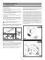
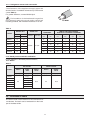
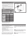
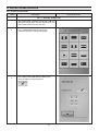
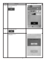
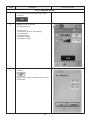
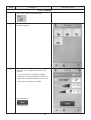
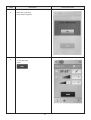
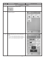
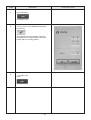
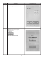
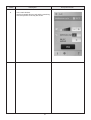
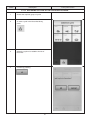
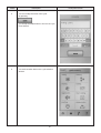
1
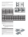
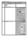
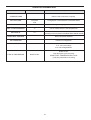
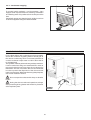
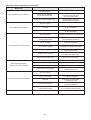
U S E
A N D
MAINTENANCE
INSTRUCTIONS
N°REV
DESCRIZIONE REVISIONE
DATA REV.
REVISORE
Dear Customer,
We would like to thank you for your trust in choosing an IRINOX blast chiller. Please read the manual carefully, it will
give you all of the information necessary to keep your products in excellent state immediately.
It is therefore recommended to study this manual in order to make use of all potentialities and advantages that your
IRINOX blast chiller can give you.
The correct functioning of the machine also depends on correct use.
Keep this manual near to the blast chiller, in a way that it can be consulted easily by yourself and the operators.
Enjoy your job with IRINOX!
Register with the Club Irinox online:
www.irinox.com
The graphical representation of the controls present in the manual is aimed at making comprehension of the operations to be performed easier, in a way to use the IRINOX blast chiller immediately and with satisfaction.
Symbols key
suggestions and details for correct use of the blast chiller
standards for your safety
additional information in this manual
Information regarding the warranty and assistance
Warranty validity: of the individual parts for 12 months from the date of invoicing, as stated in the price list in force.
Contacts:
Customer service
User assistance
Technical - spare parts after-sales
Fax
E-mail
Web site
+39.0438.5844
+39.0438.5844
+39.0438.2020
+39.0438.2023
[email protected]
www.irinox.com
For every request relative to your blast chiller, always indicate:
• The model
• The serial number
stated on the label on the model
INDEX
1. GENERAL DOCUMENTATION
1.1 GENERAL RECOMMENDATIONS
1.2 FOREWORD
1.3 TRANSPORT AND HANDLING
1.4 UNPACKING
1.5 ELEMENTARY SAFETY STANDARDS
1.6 PRECAUTIONS FOR LOADING OR UNLOADING
1.7 DANGEROUS USE OF THE POINTED PROBE
1.8 PERIODICAL STAFF TRAINING
2. INSTALLATION
2.1 PLATE DATA
2.2 POSITIONING
2.3 DIMENSIONAL DATA
2.4 ENVIRONMENT TEMPERATURES AND AIR EXCHANGE
2.5 COOLING CAPACITIES
2.6 ELECTRIC CONNECTION
2.7 REFRIGERATOR CONNECTION
2.8 CONDENSATE DRAIN
2.9 WATER COOLING UNITS CONNECTION
2.10 NOTES FOR THE INSTALLER
2.11 SAFETY AND CONTROL SYSTEMS
2.12 R404A GAS SAFETY SHEET
2.13 DISPOSING OF THE MACHINE
3. OPERATION
3.1 USE
3.2 DESCRIPTION OF CYCLES
3.3 DESCRIPTION AND OPERATION
3.3.1 PRELIMINARY OPERATIONS
3.3.1.1 INITIAL START-UP
3.3.1.2 HEATING
3.3.2 SELECTING THE CYCLES
3.3.2.1 AUTOMATIC MODE
3.3.2.2 MANUAL MODE
3.3.2.3 FAVOURITES
3.3.2.4 DEFROST
3.3.2.5 COOLING AND FREEZING
3.3.2.6 THAWING
3.3.2.7 COOKING AT LOW HEAT
3.3.2.8 PROOFING
3.3.2.9 PASTEURISATION
3.3.3 FUNCTIONS
3.3.3.1 CONTINUOUS CYCLE
3.3.3.2 TURNING OUT
3.3.3.3 CORE PROBE TEMPERATURE INDICATION
3.3.3.4 ENTERING CYCLES IN THE FAVOURITES AREA
3.3.3.5 RECORDING CYCLES
3.3.2.6 DISABLING THE KEYBOARD
3.4 STOPPING MODES
3.5 RECOMMENDATIONS FOR USE
3.6 PROGRAMMING THE PARAMETERS
3.6.1 CONFIGURING THE OPERATOR PARAMETERS
3.6.2 MODIFYING THE CYCLE PARAMETERS
3.7 SANIGEN
4. MAINTENANCE / SERVICE
4.1 ROUTINE MAINTENANCE
4.2 CLEANING THE CHAMBER
4.3 CLEANING THE CONDENSER
4.4 TROUBLE SHOOTING
4.5 EXTRAORDINARY MAINTENANCE
4
4
4
4
4
5
5
5
5
6
6
6
7
10
10
10
13
14
15
15
16
16
17
18
18
18
23
23
23
24
25
27
28
30
31
32
33
35
37
38
39
39
43
44
45
47
49
50
50
53
53
55
57
61
61
61
63
64
66
1. GENERAL DOCUMENTATION
1.1. GENERAL RECOMMENDATIONS
•
• This manual is an integral part of the product, it
supplies all of the indications necessary for correct
installation, correct use and maintenance of the
machine.
• It is mandatory for the user to read this manual carefully
and always make reference to it. Moreover, it must
be kept in place that is known and accessible to the
authorised operators (installer, user, maintenance
technician)
• The blast chiller is intended for professional use and
therefore only qualified staff can use it
• The blast chiller is destined only for the use for which
it has been designed.
• The manufacturer declines all responsibility for any
damage caused by incorrect or unreasonable use,
as for example:
- improper use by untrained staff.
- modification or interventions that are not specific for
the model.
- use of non-original spare parts or that are not specific
for the model.
- failure to comply, even partial, with the instructions
in this manual.
1.2 FOREWORD
Installation must be carried out by authorised and
specialised staff, respecting the instructions in this
manual. The manufacturer declares and assigns a
Declaration of Conformity to the 98/37 Machinery
Directive, to the 2006/95 Directive and to the
2004/108/CE Directive to each individual machine.
In compliance with directive 97/23/EC, based on the
model the equipment is supplied together with the user
manuals and declarations of conformity of the:
• safety valve;
• liquid receiver;
• liquid separator;
• liquid receiver + separator;
• compressors
• oil separator;
• safety pressure switches.
The joints made by IRINOX S.p.a. comply with the
standard EN14276-2
Whenever the machine is supplied with the remote
condensing unit, it is the installer’s responsibility to
check all connections and issue a declaration of
perfect execution and is in compliance with the provisions of the above-mentioned Directive.
The joints made by IRINOX S.p.a. comply with the
standard EN14276-2
IMPORTANT NOTE: IRINOX reminds you that all the
machines must undergo periodical inspections in compliance with national standards in force.
In particular, from the Italian market: the plant must be
fully inspected, especially the integrity of the pressurised chiller circuits, after ten years of operation, as
required in Italy by Annex B of the Ministerial Decree 1
December 2004 n°329 for assemblies belonging to
categories I-IV containing fluids of group 2.
1.3 TRANSPORT AND HANDLING
• The loading and unloading of the appliance from the
means of transport can be performed using a fork lift
truck or transpallets with forks that have a length
exceeding half of the length of the object. The lifting
means must be adequately selected on the basis of the
dimensions and weight of the packaged machine,
indicated on the labels of the packaging.
• All necessary precautions must be adopted when
handling the appliance in order not to damage it,
respecting the indications positioned on the packaging.
1.4. UNPACKING
• Remove the cardboard or wooden packaging or
crate from the wooden base on which the blast chiller
is rested. Lift the blast chiller using suitable means
(fork lift truck), remove the wooden base and position
the machine in the envisioned place (see par. 2.2).
• After the packaging has been removed, check the
integrity of the blast chiller.
• Remove the protective PVC film from all sides (Fig.1).
When handling the packaging and the wooden
base, use protective gloves.
N.B.: all of the various packaging components must
be disposed of according to the Standards in force in
the Country where the appliance is used. In all cases,
nothing must be dispersed into the environment.
Fig. 1
4
1.5. ELEMENTARY SAFETY STANDARDS
between the protections and the moving parts.
• before carrying out cleaning operations or routine
maintenance, disconnect the machine from the
power supply mains, switching the master switch off
and removing the plug.
• do not pull the power supply cable to disconnect the
machine from the power supply mains.
The responsibility of the operations performed on the
machine, ignoring the indications stated in this
manual, is implemented by the user.
Below find the main general Safety Standards:
• do not touch the machine with humid or wet hands
and feet
• do not operate the machine with bare feet
• do not insert screwdrivers, kitchen tools or other
1.6. PRECAUTIONS FOR LOADING OR UNLOADING
LOADING
• When loading the machine, the use of kitchen gloves
is recommended in order to prevent burns on contact
with the hot trays and trolleys.
UNLOADING
• When the blast chilling and/or freezing cycle is
terminated, open the door slowly until the fans stop.
• Extract the product core probe/s and position it/them
on the probe/holder.
• Use gloves suitable for trays and cold trolleys.
USE OF
THE POINTED
PROBE
1.7. DANGEROUS
USO PERICOLOSO
DELLA
SONDA APPUNTITA
Use of the probe is only allowed by authorised staff,
trained regarding use of the blast chiller.
The core probe must only be used for the purpose for
which it has been designed: to detect the temperature
at the centre of the food stuffs to be blast chilled and/or
frozen.
Handle the probe with care. Its end is pointed to make
insertion into the product to be blast chilled and/or
frozen easier.
The ergonomic grip allows correct extraction and
insertion.
STAFF
TRAINING
1.8. PERIODICAL
FORMAZIONE
PERIODICA
DEL PERSONALE
It is recommended to carry out periodical training of all
staff, which is authorised to operate on the machine,
regarding Safety Standards (installer, user, maintenance
technician).
To prevent accidents or damage to the equipment, it is
also recommended to periodically train staff regarding
use and maintenance of the temperature blast chiller,
making reference to this manual, which must be kept
near to the machine, in a known and accessible place.
IRIN
Blas OX
Chill t
er
5
2. INSTALLATION
2.1. PLATE DATA
• Check that the plate data and the characteristics of
the electric line correspond (V, kW, Hz, n° phases
and power available)
• The plate with the appliance features is applied on the
side (fig.2).
The eventual preparation of machine rooms for positioning
the condensing units must follow the Standards in force
in the country of installation regarding fire-prevention
(contact the local fire department for the due indications).
31020
CORBANESE (TV)
ITALY
Model
Serial N°
mm/yy/progres.
Mod.
s/n
Ph
V
Hz
Kw
A
It must also be considered that any intervention of
the safety valve or fuse caps, currently in the refrigerator
circuit, leads to the immediate discharge of all refrigerant
u s e d i n t h e e n v i r o n m e n t . C o n s e q u e n t l y, r e a l i s e
appropriate means of disposal and first aid as indicated in
the refrigerant safety sheet (see par. 2.12).
HERMETIC
Compressor
Refrigerant
R404
Frequency
Charge
Power
Desing pressure (Low)
KPa
Desing pressure (High)
KPa
Class
Volume
Phase
Volt
Rated Load
IP
Climatic Class:
• 4 (environment temperature 30°C with relative
humidity 55% non condensing) according to IEC EN
60335-1, IEC EN 60335-2-89, ISO 23953-2:2005 (E)
Standards
Absorption
PED Code
Fig. 2
2.2. POSITIONING
• The remote units are manufactured to be installed in
places protected against adverse weather conditions.
The plants must be positioned on a levelled cement or
steel base and must have the maintenance space
according to the technical files. If installed on the roof
or attic, beams should be provided which divide the
weight. Furthermore the base must be sufficiently
sturdy and capable of bearing the weight of the complete unit resulting from the technical data of the
specific drawing. To avoid further vibrations or noise,
it is recommended to use neoprene anti-vibration
pads underneath the corners of the unit's base.
• The blast chiller must be installed and inspected
with complete respect of the accident-prevention
legal Standards, traditional regulations and
Standards in force.
• The installer must check any provisions on the
subject of fire-prevention (contact the local fire
department for the due indications).
• Place the blast chiller in the place envisioned.
• Level the appliance using the adjustable feet. Use
the relative lifting devices to level heavier machines
(Fig.3).
• If the appliances are not levelled, their functioning
ad the flow of condensate can be compromised.
To avoid (Fig.4):
• If the blast chiller/conserver is installed below floor
level or underground, the installer must apply the
clauses foreseen by the standard EN378-1:2008
+A1:2010 ANNEX D to guarantee that no one can
remain locked inside the cell at the end of the work
shift.
• Places exposed to direct sunlight
• Closed places with high temperatures and low air
exchange (see Table 2).
• Do not install the machine near to any heat source.
• The blast chiller/conserver can be installed underground or on a loft as long as there are adequate
emergency exits as foreseen by the standard
EN378-1:2008+A1:2010 ANNEX C.
• The installer must verify the need for forced ventilation
inside a room where the blast chiller/conserver is
installed as foreseen by the standard EN3782:2008+A1:2009 chapter 6.2.14.
6
2.3. DIMENSIONAL DATA
FRONT
VIEW
SIDE
VIEW
UPPER
VIEW
MF20.1
MF45.1
MF70.1
7
2.3. DIMENSIONAL DATA
FRONT
VIEW
SIDE
VIEW
UPPER
VIEW
MF30.2
MF70.2
MF85.2
8
2.3. DIMENSIONAL DATA
MF45.1 condensing unit
MF45.1 condensing unit
MF70.1 / MF70.2 / MF85.2 condensing unit
P1
L1
P1
L1
P1
L1
H1
H1
H1
Remote condenser
Remote condenser
P1
P1
H1
H1
Super silenced
remote condenser
Super silenced
remote condenser
L1
Air cooled remote unit
H
P
L1
Air cooled remote unit
H
H
L
P
P
L
L1
L1
H1
Remote unit and
remote air condenser
L
H1
Remote unit and
remote air condenser
P1
H
P
P1
H
L
P
L
L1
L1
Remote unit and H1
super silenced
remote air condenser
Remote unit
and super silenced
remote air condenser
H1
H
P1
P
P1
H
L
L
P
Case option
Case option
H
P
H
H
L
P
P
L
Remote condenser dimensions.
9
SUPER SIL. AIR
STD.AIR
STD.AIR
SUPER SIL. AIR
ARIA STD.
SUPER SIL. AIR
STD.AIR
MF85.2
SUPER SIL. AIR
DIM.
(cm)
L1
P1
H1
Kg
79 79 80
84 84 85
64 56 67
102 81 121
MF70.1 MF30.2 MF70.2
STD.AIR
MF25.1 MF45.1
59
27
29
5.6
58
31
51
13
89
50
60
23
59
33
51
21
111
60
75
33
59
27
29
5.6
58
40
51
21
111
60
75
33
58 167
40 60
51 75
21 41
MOD.
CASED
REMOTE COND
79 80
84 85
56 67
64 111.5
AIR
REMOTE COND
79
84
64
85
CASED
AIR
79 80 78 78
84 85 62 63
56 67 38 41
72 111.5 40.5 51
AIR
79
84
64
93
CASED
MOD.
MF85.2
CASED
MF70.2
REMOTE COND
MF30.2
AIR
79 80
84 85
56 67
64 103.5
CASED
REMOTE COND
79
84
64
85
MOD.
78 78
62 63
37 41
40.5 51
AIR
DIM.
(cm)
L
P
H
Kg
MF70.1
AIR
MF45.1
CASED
MF25.1
STD.AIR
Remote condensing unit dimensions.
MOD.
L
2.4. ENVIRONMENT TEMPERATURES AND AIR EXCHANGE
Table 2
For air-cooled chiller units, the temperature of the
functioning environment must not exceed 32 °C. The
performance declared is not guaranteed over this
temperature.
The remote condensing units must be installed in
opposite rooms or outdoors, in a place protected from
direct sunlight. If the circumstances should make it
necessary, the installer must evaluate whether the use
of a cover or roof is required (in all cases sufficient air
exchange must be guaranteed).
MINIMUM AIR EXCHANGE MODEL
CHAMBER
MF25.1
MF45.1
MF70.1
MF30.2
For further details see Table 2.
MF70.2
MF85.2
Power supply
frequency (Hz)
AIR (m3/h)
50
60
50
60
50
60
50
60
50
60
50
60
1100
1210
3000
3300
4000
4400
1100
1210
4000
4400
4000
4400
2.5. COOLING CAPACITIES
Table 3
CHAMBER
Power supply
frequency (Hz)
Condensing power (W)
Cooling efficiency (W)
50
1727
2683
60
1623
2549
9075
50
6013
MF45.1
11038
60
7216
13053
50
8851
MF70.1
60
15548
10305
50
2427
3712
MF30.2
60
2591
4012
50
8851
13053
MF70.2
60
10305
15548
50
10853
15842
MF85.2
60
12776
19225
Values declared at T.evap.=-10°C, T.cond.=+40°C and power supply f.=50Hz.
Over-heating in compliance with EN12900
MF25.1
2.6. ELECTRIC CONNECTION
Install an automatic differential magnet-circuit breaker
switch upstream from every appliance, according to
the Standards in force in the country of installation.
The manufacturer declines all liability and
every warranty obligation, whenever the appliance
or objects are damaged and persons are injured
due to incorrect installation and/or failure to comply
with the laws in force.
The size of the connection cables must comply with
the information contained in the electric data of the
technical files. The voltage of the plants must be within
the limit of +10% and voltage unbalance of the phases
must not exceed 3%. The electric power connection
must be carried out by qualified personnel, in compliance with the directives and laws of the country where
the unit is installed.
The power supply must be taken to the blast chiller
electric control board, according to the data given in
Table 4.
• The electric power supply cables must be correctly
dimensioned and selected depending on the real
laying conditions;
• The electric cables must be introduces and blocked
in the relevant fairlead and placed in a suitable
manner depending on the place of installation;
• Every wire must be inserted into the corresponding
clamp;
• The earth wire must be correctly connected to an
efficient earth plant.
Fig. 5
10
Fig. 6
Table 4
CHAMBER
CONDENSING
UNIT
Air
MF25.1
Air remote
condenser
Water
Air
Air remote
condenser
MF45.1
Super Silenced
Air remote
condenser
Water
Air
Air remote
condenser
MF70.1
Super Silenced
Air remote
condenser
Water
CABLE SECTIONS
POWER SUPPLY
FOR REMOTE
CABLE SECTION
Power (kW) Current (A)
CONDENSING UNITS *2
*1
POWER SUPPLY
Voltage (V) Frequency (Hz)
230
230
200/208
200/208
230
230
200/208
200/208
230
230
200/208
200/208
400
400
230
230
200/208
200/208
400
400
230
230
200/208
200/208
400
400
230
230
200/208
200/208
400
400
230
230
200/208
200/208
400
400
230
230
200/208
200/208
400
400
230
230
200/208
200/208
400
400
230
230
200/208
200/208
400
400
230
230
200/208
200/208
50
60
50
60
50
60
50
60
50
60
50
60
50
60
50
60
50
60
50
60
50
60
50
60
50
60
50
60
50
60
50
60
50
60
50
60
50
60
50
60
50
60
50
60
50
60
50
60
50
60
50
60
50
60
50
60
50
60
50
60
ABSORPTION
Poles
1P+N+PE
1P+N+PE
2P+PE
2P+PE
1P+N+PE
1P+N+PE
2P+PE
2P+PE
1P+N+PE
1P+N+PE
2P+PE
2P+PE
3P+N+PE
3P+N+PE
3P+PE
3P+PE
3P+PE
3P+PE
3P+N+PE
3P+N+PE
3P+PE
3P+PE
3P+PE
3P+PE
3P+N+PE
3P+N+PE
3P+PE
3P+PE
3P+PE
3P+PE
3P+N+PE
3P+N+PE
3P+PE
3P+PE
3P+PE
3P+PE
3P+N+PE
3P+N+PE
3P+PE
3P+PE
3P+PE
3P+PE
3P+N+PE
3P+N+PE
3P+PE
3P+PE
3P+PE
3P+PE
3P+N+PE
3P+N+PE
3P+PE
3P+PE
3P+PE
3P+PE
3P+N+PE
3P+N+PE
3P+PE
3P+PE
3P+PE
3P+PE
NOTES: *1 cable dimensioned for a length of 6m;
*2 cable dimensioned for a length 25m.
Industrial voltage drop ∆V% ≤ 1%; FG7OR type cable
11
1,2
1,3
1,3
1,3
1,3
1,3
1,3
1,3
1,1
1,2
1,2
1,2
3,6
3,7
3,8
4,5
4,5
4,5
3,7
3,8
3,8
4,6
4,5
4,5
3,7
3,8
3,8
4,6
4,5
4,5
3,6
3,6
3,7
4,4
4,4
4,4
5,3
5,4
5,3
6,6
5,7
6,7
5,4
5,5
5,3
6,6
5,6
6,8
5,3
5,3
5,2
6,5
5,1
6,3
5,1
5,1
5,1
6,3
5,1
6,3
6,5
6,3
6,5
6,4
6,9
6,6
6,8
6,7
6,1
5,9
6,1
6,1
5,6
5,9
14,3
14,6
12,6
12,6
5,6
6,0
14,6
14,8
12,8
12,8
5,7
6,0
14,6
14,8
12,8
12,8
5,5
5,7
14,3
14,4
12,5
12,5
10,8
11,6
26,2
26,3
26,7
26,8
10,8
11,7
26,5
26,5
26,9
27,0
10,8
11,6
26,4
26,3
26,0
25,9
10,6
11,4
26,0
25,9
26,0
25,9
3G2,5mmq + 3x1,5mmq
3G2,5mmq
5G2,5mmq
4G2,5mmq + 10x1,5mmq
4G4mmq + 10x1,5mmq
4G2,5mmq
4G6mmq + 10x1,5mmq
5G2,5mmq
4G2,5mmq + 10x1,5mmq
4G4mmq + 10x1,5mmq
4G2,5mmq
4G6mmq + 10x1,5mmq
5G2,5mmq
4G2,5mmq + 10x1,5mmq
4G4mmq + 10x1,5mmq
4G2,5mmq
4G6mmq + 10x1,5mmq
5G2,5mmq
4G2,5mmq + 10x1,5mmq
4G4mmq + 10x1,5mmq
4G2,5mmq
4G6mmq + 10x1,5mmq
5G2,5mmq
4G2,5mmq + 10x1,5mmq
4G6mmq + 10x1,5mmq
4G4mmq
4G10mmq + 10x1,5mmq
5G2,5mmq
4G2,5mmq + 10x1,5mmq
4G6mmq + 10x1,5mmq
4G4mmq
4G10mmq + 10x1,5mmq
5G2,5mmq
4G2,5mmq + 10x1,5mmq
4G6mmq + 10x1,5mmq
4G4mmq
4G10mmq + 10x1,5mmq
5G2,5mmq
4G2,5mmq + 10x1,5mmq
4G6mmq + 10x1,5mmq
4G4mmq
4G10mmq + 10x1,5mmq
Table 4
CHAMBER
CONDENSING
UNIT
Air
MF30.2
Air remote
condenser
Water
Air
Air remote
condenser
MF70.2
Super Silenced
Air remote
condenser
Water
Air
Air remote
condenser
MF85.2
Super Silenced
Air remote
condenser
Water
CABLE SECTIONS
POWER SUPPLY
FOR REMOTE
CABLE SECTION
Power (kW) Current (A)
CONDENSING UNITS *2
*1
POWER SUPPLY
Voltage (V) Frequency (Hz)
230
230
200/208
200/208
230
230
200/208
200/208
230
230
200/208
200/208
400
400
230
230
200/208
200/208
400
400
230
230
200/208
200/208
400
400
230
230
200/208
200/208
400
400
230
230
200/208
200/208
400
400
230
230
200/208
200/208
400
400
230
230
200/208
200/208
400
400
230
230
200/208
200/208
400
400
230
230
200/208
200/208
50
60
50
60
50
60
50
60
50
60
50
60
50
60
50
60
50
60
50
60
50
60
50
60
50
60
50
60
50
60
50
60
50
60
50
60
50
60
50
60
50
60
50
60
50
60
50
60
50
60
50
60
50
60
50
60
50
60
50
60
ABSORPTION
Poles
1P+N+PE
1P+N+PE
2P+PE
2P+PE
1P+N+PE
1P+N+PE
2P+PE
2P+PE
1P+N+PE
1P+N+PE
2P+PE
2P+PE
3P+N+PE
3P+N+PE
3P+PE
3P+PE
3P+PE
3P+PE
3P+N+PE
3P+N+PE
3P+PE
3P+PE
3P+PE
3P+PE
3P+N+PE
3P+N+PE
3P+PE
3P+PE
3P+PE
3P+PE
3P+N+PE
3P+N+PE
3P+PE
3P+PE
3P+PE
3P+PE
3P+N+PE
3P+N+PE
3P+PE
3P+PE
3P+PE
3P+PE
3P+N+PE
3P+N+PE
3P+PE
3P+PE
3P+PE
3P+PE
3P+N+PE
3P+N+PE
3P+PE
3P+PE
3P+PE
3P+PE
3P+N+PE
3P+N+PE
3P+PE
3P+PE
3P+PE
3P+PE
NOTES: *1 cable dimensioned for a length of 6m;
*2 cable dimensioned for a length 25m.
Industrial voltage drop ∆V% ≤ 1%; FG7OR type cable
12
1,6
1,8
1,9
1,8
1,7
1,9
1,9
1,9
1,5
1,8
1,8
1,8
5,2
5,3
5,2
6,5
5,4
6,6
5,3
5,4
5,2
6,5
5,5
6,7
5,2
5,2
5,1
6,4
5,0
6,2
5,0
5,0
5,0
6,2
5,0
6,2
6,2
7,8
6,0
7,9
6,3
8,0
6,2
7,9
6,1
7,9
6,3
8,1
6,2
7,8
6,0
7,9
5,8
7,6
6,0
7,5
5,8
7,6
5,8
7,6
7,1
11,5
11,6
11,5
7,4
11,8
12,0
11,9
6,8
11,1
11,2
11,1
10,6
11,4
25,9
25,9
26,3
26,5
10,7
11,5
26,1
26,1
26,6
26,7
10,6
11,4
26,0
26,0
25,7
25,6
10,4
11,2
25,7
25,6
25,8
25,6
13,5
15,0
31,0
32,5
31,5
33,1
13,6
15,1
31,3
32,8
31,7
33,3
13,6
15,2
31,3
32,8
30,9
32,3
13,3
14,8
30,8
32,2
30,9
32,3
3G4mmq + 3x1,5mmq
3G6mmq + 3x1,5mmq
3G4mmq + 3x1,5mmq
3G2,5mmq
3G6mmq + 3x1,5mmq
3G4mmq + 3x1,5mmq
3G6mmq + 3x1,5mmq
5G2,5mmq
4G2,5mmq + 10x1,5mmq
4G6mmq + 10x1,5mmq
4G4mmq
4G6mmq + 10x1,5mmq
5G2,5mmq
4G2,5mmq + 10x1,5mmq
4G6mmq + 10x1,5mmq
4G4mmq
4G6mmq + 10x1,5mmq
5G2,5mmq
4G2,5mmq + 10x1,5mmq
4G6mmq + 10x1,5mmq
4G4mmq
4G6mmq + 10x1,5mmq
5G2,5mmq
4G2,5mmq + 10x1,5mmq
4G6mmq + 10x1,5mmq
4G4mmq
4G6mmq + 10x1,5mmq
5G2,5mmq
4G2,5mmq + 10x1,5mmq
4G6mmq
4G6mmq + 10x1,5mmq
4G10mmq
4G10mmq + 10x1,5mmq
5G2,5mmq
4G2,5mmq + 10x1,5mmq
4G6mmq
4G6mmq + 10x1,5mmq
4G10mmq
4G10mmq + 10x1,5mmq
5G2,5mmq
4G2,5mmq + 10x1,5mmq
4G6mmq
4G6mmq + 10x1,5mmq
4G10mmq
4G10mmq + 10x1,5mmq
5G2,5mmq
4G2,5mmq + 10x1,5mmq
4G6mmq
4G6mmq + 10x1,5mmq
4G10mmq
4G10mmq + 10x1,5mmq
2.7. REFRIGERATOR CONNECTION
2.7.1. Installation at equal level
General criteria that must be satisfied in the installation
of the remote units:
1) Wire gradients (Fig.7)
2) Fastening brackets onto the insulated pipes (Fig.8)
3) Hermetic sealing (Fig.9).
4) Execution of the vacuum (0.03mBar) in the connection
pipes (flow and intake). The condensing unit is loaded
with freon unless differently indicated.
If the heat exchangers of the blast chiller/conserver
can be shut off from the rest of the plant by means of
valves, these exchangers must be protected by
adequate safety devices as foreseen by the standard
EN378-2:2008+A1:2009 chapter 6.2.6.8.
For water condensed units or units with heat recovery:
when choosing and installing water piping, follow the
local provisions and regulations concerning constructions and safety standards. The installer must take care
of the mechanical coupling of connections having
dimensions appropriate for the system and make sure
that the water inlet and outlet connections agree with
the dimensional drawing and with the stickers on the
connections. The piping must be supported to reduce
the weight and tension on the connections. An inspectionable filter which filters solid bodies must be
installed on the inlet pipe of the heat exchanger.
If noise and vibrations are critical, anti-vibration fittings
must be installed on the inlet and outlet water pipes of
the heat exchangers.
5) Check vacuum sealing of the pipes.
6) Opening of the cut-off cocks on the condensing unit.
7) Leak control.
8) Control of the exact gas load via the liquid passage
indicator light positioned on the condensing unit.
9) Control of the circulation and pressure of the condensing
water (systems with water cooling).
The criteria indicated above are sufficient for
installation at equal level (Fig.10)
Length-adjustable piping must be installed, using
supports which allow it to slide and provided with
sufficient space near walls and other constraints.
Equal level
installation
2%
CO
MP
Fig. 7
RE
SS
OR
Fig. 8
Fig. 9
Fig. 10
2.7.2. Installation at equal level
Different level
installation
If the remote unit is installed higher with respect to the
appliance (fig.12), a siphon must be installed at every
start-up or re-ascent (a), every 1.8 metres difference in
level along the return pipe and at ever arrival (b).
If the remote unit is installed lower with respect to the
appliance, no siphon is necessary (Fig. 11, Fig. 12).
Fig. 11
13
Fig. 12
2.7.3. Refrigerator-remote units connection
The diameters of the appliance supply pipes are
dimensioned or installation distances up to 25 metres
(see Table 5).
For greater distances, contact IRINOX SpA.
The insulation of the intake and hot gas line
must be performed using good quality closed cell
insulating material, with minimum thickness of 19 mm.
19 mm
Table 5
REMOTE UNIT
MODEL
REMOTE
CONDENSER
WATER UNIT
ø Liquid
ø Intake
mm
MF25.1
REMOTE UNIT AND STANDARD
REMOTE OR S. SILENCED CONDENSER
ø IN cond.
ø OUT cond.
ø IN cond.
ø OUT cond.
ø Liquid
ø Intake
mm
mm
mm
mm
mm
mm
mm
8
10
8
8
/
/
/
/
MF45.1
10
16
12
10
12
10
10
16
MF70.1
12
22
16
12
16
12
12
22
MF30.2
8
10
8
10
/
/
/
/
MF70.2
12
22
16
12
16
12
12
22
MF85.2
12
28
16
12
16
12
12
28
ø IN water
Fe 3/8"
ø OUT water
Fe 3/8"
2.7.4 R404a pressure switches calibration
For the calibration of the R404a pressure switches,
see Table 6
Table 6
AIR COOLED
MODEL
HIGH P.
START
VENT.
SAFETY
VALVE
HIGH P.
SAFETY
VALVE
(Bar)
(Bar)
(Bar)
(Bar)
(Bar)
28.5
25
28,5
MF25.1
17(*1)
MF45.1
17
MF70.1
MF30.2
25
17
17(*1)
MF70.2
17
MF85.2
17
*1:
WATER COOLED
Only when the condensing unit or the condenser is remote.
2.8. CONDENSATE DRAIN
The blast chillers have a basin for the collection of
condensate. The basin can be extracted from the lower
part of the Blast chiller.
14
2.9. WATER COOLING UNITS CONNECTION
• On inspection (mains water), with the machine at a
standstill and water network ready, check that the
condenser drain pipe does not allow water to
escape. If this is not case, regulate the pressure valve
until the leak stops (Fig.13).
• It is recommended to supply a gate valve and an
inspectionable filter in the water flow line. The
condenser water flow and drain pipes are indicated
by relevant plates. Both connections are 3/8”F and
threaded.
• See Table 7 for maximum water consumption
FEATURES OF THE LINE FOR WATER COOLED
CONDENSING UNITS
Maximum pressure of the inlet water
1600 KPa
Minimum pressure of the inlet water
50 KPa
Maximum temperature of the inlet water in order
22°C (well water)
to guarantee normal appliance functioning.
35°C (tower water)
Values referring to a water inlet temperature = 15°C
Fig. 13
Table 7
MAXIMUM WATER CONSUMPTION
CHAMBER
MF25.1
MF45.1
MF70.1
MF30.2
MF70.2
MF85.2
Power supply
frequency (Hz)
l/h
WATER
m3/h
50
60
50
60
50
60
50
60
50
60
50
60
128
103
345
435
516
616
178
192
516
616
630
760
0.13
0.10
0.35
0.44
0.52
0.62
0.18
0.19
0.52
0.62
0.63
0.76
Values referring to a water inlet temperature = 15°C
Inlet water maximum temperature = 22°C
Maximum water pressure entering the condenser = 1600kPa
Minimum inlet water pressure = 150KPa
2.10. NOTES FOR THE INSTALLER
For loads with more than 100 kg of refrigerant, adequate
overflow devices must be installed by the installer as
foreseen by the standard EN378-2:2008+A1:2009
ANNEX F.
Verification of correct installation and inspection:
• Check for any gas leaks from the seals or joints
made during the installation phase.
• Check the good insulation of the connection pipes
between preserving unit and remote condensing unit.
• Check the electric connection.
• Check absorption.
• Verify the standard pressures.
• Check the water connection with the regulation of the
pressure valve during functioning
along with the good circulation of the condensation
water.
Inform the customer regarding the exact use
of the appliance with specific reference to use and
the requirements of the customer himself.
The safety devices must be installed in such a way that
leakage of refrigerant cannot cause any danger. When
installing the pressure release piping of the safety
valves, the line must comply with local standards.
Installation and the start-up must be performed
by authorised staff
15
2.11. SAFETY AND CONTROL SYSTEMS
• Door micro switch (A): blocks fan functioning in the
chamber when the door is opened.
• Protection fuses (B): they protect the circuits from
short circuits and overloads.
• Fuse-holders (C): they contain the fuses and they
allow the opening and isolating of the circuits.
• Circuit boards (D): on the basis of the parameters
acquired, the control the various blast chiller devices
connected to it.
• Controls temperature in chamber (E): it is managed
by the circuit board via PT1000 probe.
• Safety pressure switch (F): it intervenes in the case of
excessive pressure in the refrigerant circuit.
• Safety valve (G): intervenes in the case of excessive
pressure in the system and lack of intervention of the
safety pressure switch. The intervention discharges
the gas in excess in the environment.
Fig.A
Fig.B
Fig.C
Fig.D
Fig.E
Fig.F
Fig.G
Fig. 14
2.12. R404A GAS SAFETY SHEET
• Identification of dangers
Ingestion
Do not induce vomiting.
If the accident victim is conscious, rinse the mouth with
water and make him/her drink 200-300 ml of water.
High exposure to inhalation can have anaesthetic
effects. Very high exposure can cause anomalies of the
heart beat and cause sudden death. The neubulised or
sprayed product can cause cold burns to the eyes or
skin. Dangerous for the ozone layer.
Further medical care
Symptomatic treatment and support therapy when
indicated. Do not give adrenalin and similar
sympathomimetic drugs following exposure, due to the
risk of cardiac arrhythmia with possible cardiac arrest.
• First aid measures
Inhalation
Move the accident victim away from exposure and keep
him/her warm and rested. Give oxygen if necessary.
Perform artificial respiration if breathing stops or gives
signs of stopping. In the case of cardiac arrest, perform
external cardiac compression.
Request immediate medical assistance.
• Fire-prevention measures
Not inflammable.
The heat decomposition causes the emission of very
toxic and corrosive vapours (hydrogen chloride,
hydrogen fluoride). In the case of fire, use respiratory
aids and suitable protective clothing.
Contact with the skin
Thaw the affected areas using water.
Remove contaminated clothing.
Attention: clothing can stick to the skin in the case of
cold burns. In the case of contact with the skin, wash
immediately with plenty of warm water. If symptoms
occur (irritation or the formation of blisters) request
medical assistance.
Extinguishers
Use extinguishing agents that are appropriate for the
fire.
• Toxological information
Inhalation
Higher atmospheric concentrations can cause anaesthetic
effects with possible loss of consciousness.
Very high exposure can cause anomalies of the heart
beat and cause sudden death.
Higher concentrations can cause asphyxia due to the
reduced content of oxygen in the atmosphere.
Contact with the eyes
Wash immediately with an eyewash or clean water,
keeping the eyelids open for at least 10 minutes.
Request immediate medical assistance.
16
Contact with the skin
• Measures in the case of accidental leaks
Ensure adequate personal protection (with the use of
means of protection for the respiratory tract) during the
elimination of spills.
If the conditions are sufficiently safe, isolate the source
of the leak. In the presence of spills of modest size,
leave the material to evaporate on the condition that
there is suitable ventilation.
Large leaks
-ventilate the area;
-contain the leaking material with sand, earth or other
suitable absorbent material;
-prevent the liquid from penetrating drains, sewers,
basements and work holes, because the vapours can
create a suffocating atmosphere.
cold burns.
It is improbable that it is dangerous due to cutaneous
absorption.
Repeated and prolonged contact can cause the removal
of sebaceous matter, with consequent dryness, cracking
and dermatitis.
• Ecological information
It decomposes relatively quickly in the lower atmosphere
(troposphere). The decomposition products are highly
dispersed and therefore have a very low concentration.
Does not affect photochemical smog (i.e. it does not lie
within the volatile organic compounds -VOC- according
to that established by the UN/ECE agreement).
The ozone destruction potential (ODP) is 0.055 measure
in comparison with a standard ODP equal to 1 for the
cfc11 (according to uNeP definitions).
The substance is governed by the Montreal Protocol
(revision dated 1992).
The discharges of the product into the atmosphere do
not cause contamination of waters in the long term.
• Handling
Avoid the inhalation of high concentrations of vapours.
The atmospheric concentrations must be reduced to a
minimum and kept at the minimum level reasonably
possible, below the professional exposure limit.
The vapours are heavier than the air and therefore the
formation of high concentrations near to the ground is
possible, where ventilation is usually low. In these
cases, ensure adequate ventilation or wear suitable
protection devices for the respiratory tract with air
reserve. Avoid contact with naked flames and hot
surfaces as irritant and toxic decomposition products
can be formed. Avoid contact between the liquid and
the eyes/skin.
• Considerations regarding disposal
The best solution consists in recovery and recycling of
the product.
If this is not possible, destruction must take place in an
authorised plant equipped to absorb and neutralise the
acid gases and the other toxic products.
2.13. DISPOSING OF THE MACHINE
The machine must be demolished and disposed of
with respect to the Standards in force in the country of
installation, especially regarding the compressor
refrigerant gas and lubricant oil.
INFORMATION FOR THE USERS
On implementation of the 2002/95/CE,
2002/96/CE and 2003/108/CE Directives,
relative to the reduction of use of dangerous
substances in electric and electronic
appliances, as well as disposal of waste.
Avoid leakage of refrigerant gas in the environment by
using suitable pressurised recipients and instruments to
transfer the pressurised fluid. This operation must be
entrusted to personnel skilled in refrigeration plants.
The barred bin symbol on the appliance or package,
indicates that at the end of the product's life, it must be
collected separately from other waste.
The selective collection of this appliance at the end of
its life is organised and managed by the manufacturer.
The user that wishes to dispose of this equipment must
therefore contact the manufacturer and follow the
system that the same has adopted to allow the selective
collection of the appliance at the end of its life span.
The suitable selective collection for successive start-up
of the equipment abandoned for recycling, treatment
and compatible environmental disposal contributes to
preventing possible negative effects on the environment
and favours the re-use and/or recycling of the materials
of which the equipment is made.
The abusive disposal of the product by the owner, leads
to the application of administrative sanctions envisioned
by the Standard.
17
3. OPERATION
3.1 USE
The temperature blast chillers have been designed to
lower the temperature of foods that have just been
cooked in a way to preserve them for a longer period,
however keeping the organoleptic features unaltered.
The Multi Fresh MF range has been studied to make
this operation as easy as possible, offering a wide
customisation of cycles.
These have been studied by IRINOX S.p.A. and its
collaborators, divided into 4 specific user categories.
In this way, your blast chiller will not only be used to
blast chill products but will help you in the production
process.
3.2 DESCRIPTION OF THE CYCLES
The MF range has the following cycles:
Cycle
Description
Cycles for CATERING - COOLING
3°C DELICATE
With this cycle the temperature of the product is quickly reduced to +3°C at the core,
with a work temperature that oscillates between 0°C and +2°C.
This cycle is particularly indicated for delicate products such as:
• Mousses,
• Spoon desserts,,
• Creams,
• Desserts,
• Vegetables,
• Foodstuffs with reduced thickness
3°C STRONG
With this cycle the temperature of the product is quickly reduced to +3°C at the core,
with a work temperature that oscillates between -15°C and +2°C.
This cycle allows to greatly reduce the work times and is particularly indicated for
the following products:
• High fat content,
• Very dense,
• Large pieces,
• Packaged
Cycles for CATERING - COOLING
RICE/PASTA 3°C
Cycle dedicated to cooling rice and pasta
VEGETABLES/MUSHROOMS 3°C
Cycle dedicated to cooling vegetables and mushrooms
LASAGNA 3°C
Cycle dedicated to cooling lasagna
FISH 3°C
Cycle dedicated to cooling fish
MEAT 3°C
Cycle dedicated to cooling pre-cut meat
SOUPS/SAUCES 3°C
Cycle dedicated to cooling soups and sauces
SAVOURY TARTS 3°C
Cycle dedicated to cooling savoury tarts
CONFECTIONERY 3°C
Cycle dedicated to cooling confectionery products
BREAD 3°C
Cycle dedicated to cooling bread
Cycles for CATERING - COOLING
-18°C DELICATE
This cycle envisions two freezing phases.
In the first phase, the core temperature of the product is taken to +6°C, with a work
temperature of 0°C.
In the second phase, the core temperature of the product is taken to -18°C, with a
work temperature that can reach -40°C.
This cycle is indicated for freezing all cooked foods, in particular raised and
oven-cooked products
18
Cycle
Description
Cycles for CATERING - FREEZING
-18°C STRONG
With this cycle the temperature of the product is quickly reduced to -18°C at the core,
with a work temperature that can reach -40°C.
This cycle is particularly indicated for all raw foods and for cooked foodstuffs with a
particular thickness
VEGETABLES/MUSHROOMS -18°C Cycle dedicated to freezing vegetables and mushrooms
RICE/PASTA -18°C
Cycle dedicated to freezing rice and pasta
LASAGNA -18°C
Cycle dedicated to freezing lasagna
FISH -18°C
Cycle dedicated to freezing fish
MEAT -18°C
Cycle dedicated to freezing meat
SOUPS/SAUCES -18°C
Cycle dedicated to freezing soups and sauces
SAVOURY TARTS -18°C
Cycle dedicated to freezing savoury tarts
CONFECTIONERY -18°C
Cycle dedicated to freezing confectionery products
BREAD -15°C
Cycle dedicated to freezing bread
Cycles for CATERING - COOKING AT LOW HEAT
CHICKEN
Cycle dedicated to cooking chicken at low heat.
You can select the form of preservation at the end of the cooking cycle
(blast chilling, freezing, keeping warm).
BEEF
Cycle dedicated to cooking beef at low heat.
You can select the form of preservation at the end of the cooking cycle
(blast chilling, freezing, keeping warm).
PORK
Cycle dedicated to cooking pork at low heat.
You can select the form of preservation at the end of the cooking cycle
(blast chilling, freezing, keeping warm).
FISH
Cycle dedicated to cooking fish at low heat.
You can select the form of preservation at the end of the cooking cycle
(blast chilling, freezing, heat maintenance).
Cycles for CATERING - REGENERATION
MEAT
Cycle dedicated to regeneration of meat
FISH
Cycle dedicated to regeneration of fish
VEGETABLES
Cycle dedicated to regeneration of vegetables
BREAD
Cycle dedicated to regeneration of bread
SINGLE PORTION
Cycle dedicated to regeneration of single portions
CONFECTIONERY
Cycle dedicated to regeneration of confectionery
Cycles for CATERING - RISING
LONG
Cycle dedicated to long rising
DIRECT
Cycle dedicated to short rising
NIGHT
Cycle dedicated to rising at night
Cycles for CATERING - DEFROSTING
CHICKEN
Cycle dedicated to defrosting chicken
BEEF
Cycle dedicated to defrosting beef
PORK
Cycle dedicated to defrosting pork
FISH
Cycle dedicated to defrosting fish
19
Cycle
Description
Cycles for CATERING - MAINTENANCE
MEAT
Cycle dedicated to maintenance of meat
FISH
Cycle dedicated to maintenance of fish
VEGETABLES
Cycle dedicated to maintenance of vegetables
BREAD
Cycle dedicated to maintenance of bread
SINGLE PORTION
Cycle dedicated to maintenance of single portions
CONFECTIONERY
Cycle dedicated to maintenance of confectionery
Cycles for CATERING - PASTEURISATION
MEAT
Cycle dedicated to pasteurisation of meat
FISH
Cycle dedicated to pasteurisation of fish
VEGETABLES
Cycle dedicated to pasteurisation of vegetables
CREAMS
Cycle dedicated to pasteurisation of creams
Cycles for CONFECTIONERY - COOLING
3°C DELICATE
See the same cycle for CATERING
3°C STRONG
See the same cycle for CATERING
MIXES IN MOULDS 10°C
Cycle dedicated to cooling mixes poured into moulds
MIXES IN LAYERS 10°C
Cycle dedicated to cooling mixes in layers, such as:
• Sponge cakes
• Biscuits
CREAMS 25°C
Cycle dedicated to cooling hot creams to be taken to
a core temperature of 25°C
CREAMS 3°C
Cycle dedicated to cooling hot creams to be taken to
a core temperature of 3°C
Cycle dedicated to cooling leavened goods to be taken to
LEAVENED GOODS 20°C a core temperature of 20°C
LEAVENED GOODS 3°C
Cycle dedicated to cooling leavened goods to be taken to
a core temperature of 3°C
LEAVENED GOODS -7°C
Cycle dedicated to cooling leavened goods to be taken to
a core temperature of -7°C
MIXES 12°C
Cycle dedicated to cooling mixes
PUFF PASTRY 12°C
Cycle dedicated to cooling puff pastry
Cycles for CONFECTIONERY - FREEZING
-18°C DELICATE
See the same cycle for CATERING
-18°C STRONG
See the same cycle for CATERING
MIXES IN MOULDS
Cycle dedicated to freezing mixes poured into moulds
TARTS -18°C
Cycle dedicated to freezing tarts to be taken to a core temperature of -18°C
MIXES IN LAYERS -18°C
Cycle dedicated to freezing mixes in layers
LEAVENED GOODS -18°C
Cycle dedicated to freezing leavened goods to be taken to
a core temperature of -18°C
MOUSSES -18°C
Cycle dedicated to freezing mousses
COMPLETE MOUSSES
Cycle dedicated to freezing complete mousses
MACAROONS -18°C
Cycle dedicated to freezing macaroons
PRE-LEAVENED GOODS -18°C Cycle dedicated to freezing pre-leavened goods
20
Cycle
Description
Cycles for CONFECTIONERY - FREEZING
ICE CREAM -18°C
Cycle dedicated to freezing ice cream to be taken to
a core temperature of -18°C
ICE CREAM -12°C
Cycle dedicated to freezing ice cream to be taken to
a core temperature of -12°C
Cycles for CONFECTIONERY - COOKING AT LOW HEAT
MERINGUES
Cycle dedicated to cooking meringues at low heat.
CREME BRULEE 3°C
Cycle dedicated to cooking creme brulee at low heat.
CREME BRULEE -18°C
Cycle dedicated to cooking creme brulee at low heat.
FRUIT POCHET 3 °C
Cycle dedicated to cooking fruit pochet at low heat.
FRUIT POCHET -18 °C
Cycle dedicated to cooking fruit pochet at low heat.
DACQUOISE
Cycle dedicated to cooking dacquoise at low heat.
Cycles for CONFECTIONERY - RISING
LONG
Cycle dedicated to long rising
DIRECT
Cycle dedicated to short rising
NIGHT
Cycle dedicated to rising at night
Cycles for CONFECTIONERY - PASTEURISATION
ICE CREAM BASES
Cycle dedicated to pasteurisation of ice cream bases
CREAMS
Cycle dedicated to pasteurisation of creams
Cycles for CONFECTIONERY - CHOCOLATE
CHOCOLATE 45°C
Cycle dedicated to chocolate
CHOCOLATE -7°C
Cycle dedicated to chocolate to be taken to a core temperature of -7°C
CHOCOLATE -18°C
Cycle dedicated to chocolate to be taken to a core temperature of -18°C
COOLING
OF MOULDS
Cycle dedicated to cooling moulds
Cycles for CONFECTIONERY - FRESHENING
MIGNONS
Cycle dedicated to freshening mignons
LEAVENED GOODS
Cycle dedicated to freshening leavened goods
MIXES
Cycle dedicated to freshening mixes
ICE CREAM -15°C
Cycle dedicated to freshening ice cream
Cycles for BAKERY PRODUCTS - COOLING
3°C DELICATE
See the same cycle for CATERING
3°C STRONG
See the same cycle for CATERING
SAVOURY TARTS 3°C
Cycle dedicated to cooling savoury tarts
CREAMS 3°C
Cycle dedicated to cooling creams
LEAVENED GOODS 3°C
Cycle dedicated to cooling leavened goods
PRE-BAKED BREAD
Cycle dedicated to cooling pre-baked bread
MIXES 10°C
Cycle dedicated to cooling mixes
TARTS 3°C
Cycle dedicated to cooling tarts
21
Cycle
Description
Cycles for BAKERY PRODUCTS - FREEZING
-18°C DELICATE
-18°C STRONG
TARTS -18°C
UNCOOKED TARTS -18°C
PRE-BAKED BREAD
See the same cycle for CATERING
See the same cycle for CATERING
Cycle dedicated to freezing tarts
Cycle dedicated to freezing uncooked tarts
Cycle dedicated to freezing pre-baked bread
Cycles for BAKERY PRODUCTS - FRESHENING
LONG
DIRECT
NIGHT
Cycle dedicated to long rising
Cycle dedicated to short rising
Cycle dedicated to rising at night
Cycles for BAKERY PRODUCTS - FRESHENING
BAKED BREAD
PRE-BAKED BREAD
Cycle dedicated to freshening baked bread
Cycle dedicated to freshening pre-baked bread
Cycles for ICE CREAM INDUSTRIES - COOLING
3°C DELICATE
3°C STRONG
CREAMS 3°C
LEAVENED GOODS 3°C
See the same cycle for CATERING
See the same cycle for CATERING
Cycle dedicated to cooling creams
Cycle dedicated to cooling leavened goods
Cycles for ICE CREAM INDUSTRIES - FREEZING
-18°C DELICATE
-18°C STRONG
MOUSSES -18°C
COMPLETE MOUSSES
ICE CREAM -18°C
ICE CREAM -12°C
See the same cycle for CATERING
See the same cycle for CATERING
Cycle dedicated to freezing mousses
Cycle dedicated to freezing complete mousses
Cycle dedicated to freezing ice cream to be taken to a
core temperature of -18°C
Cycle dedicated to freezing ice cream to be taken to a core temperature of -12°C
Cycles for ICE CREAM INDUSTRIES - COOKING AT LOW HEAT
MERINGUES
FRUIT POCHET 3 °C
FRUIT POCHET -18 °C
Cycle dedicated to cooking meringues at low heat.
Cycle dedicated to cooking fruit pochet at low heat.
Cycle dedicated to cooking fruit pochet at low heat.
Cycles for ICE CREAM INDUSTRIES - RISING
LONG
DIRECT
NIGHT
Cycle dedicated to long rising
Cycle dedicated to short rising
Cycle dedicated to rising at night
Cycles for ICE CREAM INDUSTRIES - PASTEURISATION
ICE CREAM BASES
CREAMS
Cycle dedicated to pasteurisation of ice cream bases
Cycle dedicated to pasteurisation of creams
Cycles for ICE CREAM INDUSTRIES - CHOCOLATE
CHOCOLATE 45°C
CHOCOLATE -7°C
CHOCOLATE -18°C
COOLING OF MOULDS
Cycle dedicated to chocolate
Cycle dedicated to chocolate to be taken to a core temperature of -7°C
Cycle dedicated to chocolate to be taken to a core temperature of -18°C
Cycle dedicated to cooling moulds
Cycles for ICE CREAM INDUSTRIES - FRESHENING
ICE CREAM -15°C
Cycle dedicated to freshening ice cream
Cycles for ICE CREAM INDUSTRIES - MAINTENANCE
ICE CREAM -15°C
Cycle dedicated to maintenance of ice cream
22
3.3 DESCRIPTION AND OPERATION
3.3.1 Preliminary operations
Phase
Description
Front panel screen
3.3.1.1 INITIAL START-UP
1
The LANGUAGE, CURRENT DATE AND TIME and
SECTOR configuration windows appear when you
start up the machine for the first time.
2
In the LANGUAGE SELECTION window,
press the key for the required language.
3
In the DATE AND TIME SELECTION window,
enter the date by pressing the key
23
Phase
Description
Front panel screen
4
A window opens showing a calendar for
selecting the date.
5
In the DATE AND TIME SELECTION window,
set the date and time
and confirm by pressing
6
Select the unit of measurement for the
temperature and confirm by pressing
7
In the SECTOR SELECTION window,
select the icon indicating your main sector of use
and confirm by pressing
3.3.1.2 HEATING
If enabled, this is carried out automatically when
the machine remains inactive for a long period of
time.
24
3.3.2 Selecting the cycles
Phase
1
Description
Front panel screen
n the main window, the first group of cycles is
shown filtered according to sector.
1. COOLING
2. DEFROSTING
3. REGENERATION
4. RISING
5. FREEZING
6. MAINTENANCE
7. COOKING AT LOW HEAT
8. PASTEURISATION
2
Select the required function by pressing the
relative button (1-8).
3
The list of cycles in the various groups appears.
25
1
5
2
6
3
7
4
8
Phase
Description
4
Press the required cycle,
then press
5
To end the cycle, press
6
When the cycle ends,
this appears
Front panel screen
26
Phase
Description
Front panel screen
3.3.2.1 AUTOMATIC MODE
1
Insert the core probe into the product
and press
2
AUTOMATIC mode is selected
The display shows:
1
1. Current type of cycle
2. Progress of cycle as a percentage
3. Current phase
4. Air temperature
5. Core probe temperature
6. Ventilation control
3
2
3
4
5
6
To end the cycle, press
27
Phase
Description
Front panel screen
3.3.2.2 MANUAL MODE
1
Do not insert the core probe into the product
and press
2
MANUAL mode is selected.
The display shows:
3
1. Type of cycle
2. Progress of cycle as a percentage
3. Current phase
4. Air temperature
5. Duration of phase
6. Ventilation control
3
2
1
4
5
6
Pressing
allows you to change the duration of the current
phase at will.
28
Phase
Description
Front panel screen
4
Ventilation speed can be modified for each
phase in progress by pressing
5
When the cycle ends, this appears
29
Phase
Description
Front panel screen
3.3.2.3 FAVOURITES
1
To view your favourites library,
press
in the menu shown in the picture
2
You can now select
the required cycle
30
Phase
Description
Front panel screen
3.3.2.4 DEFROST
1
Press the key
2
To access the demisting cycle,
press
3
Open the door
Press
to start the cycle
4
Press the key
to modify the cycle time
31
Phase
Description
Front panel screen
3.3.2.5 COOLING AND FREEZING
1
In the main window, press the button to open
the cycle start window
2
If the automatic core probe detection function is
disabled, select the required work mode
3
When the temperature at the core reaches the
temperature set for indication, the warning
message appears
32
Phase
Description
Front panel screen
3.3.2.6 THAWING
1
In the main window, select the button
2
Select the product
3
Press key (1) to modify the thickness of the
product.
• 1st or 2nd notch for products 4 cm MAX
• 3rd notch for products between 4 and 7 cm
• 4th notch for products between 7 and 10 cm
• 5th notch for products 10 cm MAX
1
4
Press the button
?
to start the cycle
33
Phase
Description
5
When the cycle ends,
the indication appears
6
To end the cycle,
press
Front panel screen
34
Phase
Description
Front panel screen
3.3.2.7 COOKING AT LOW HEAT
1
In the main window, select the button
2
Select the product
3
Before starting the cycle, you can select how it
ends:
• +3°C: once cooked, the product is cooled
• +65°C: once cooked, the product is kept warm
• -18°C: once cooked, the product is frozen
35
Phase
4
Description
Front panel screen
Press the button
to start the cycle
5
You can set a product MATURATION phase
by pressing
The maturation phase maintains a specific
temperature for a certain length of time and
begins after the cooking phases.
6
To end the cycle,
press
36
Phase
Description
Front panel screen
3.3.2.8 PROOFING
1
THE PROOFING CYCLES ARE MANUAL ONLY
(WITH TIMER)
2
In the main window, select
3
Select the type of proofing
4
Pressing the key
allows you to set a cycle end date, in which
case proofing is postponed and the product is
kept frozen for the required length of time.
Before starting the cycle, you can select how
to end it:
• PROOFING and CHILL: after it has proofing,
the product is cooled
• PROOFING and FREEZE:
the product is frozen
5
Press the button
to start the cycle
37
Phase
Description
Front panel screen
3.3.2.9 PASTEURISATION
1
In the main window, select
2
Select the type of product
3
Before starting the cycle, you can select how it
ends:
• Pasteurise:
after pasteurisation,
the product is kept warm
• Pasteurise and cool:
after pasteurisation, the product is
cooled
• Pasteurise and freeze:
after pasteurisation, the product is
frozen
4
Press the button
to start the cycle
38
3.3.3 Functions
Phase
Description
Front panel screen
3.3.3.1 CONTINUOUS CYCLE
Function enabled only for delicate cycles at +3°C and strong cycles at -18°C in manual mode
1
With the continuous cycle function enabled, the
cycle continues indefinitely.
1. Type of cycle
2. Progress of cycle
3. Phase
4. Air temperature
5. Ventilation control
6. Enabling the CONTINUOUS CYCLE
7. Positioning and type of foodstuff
2
1
3
5
6
7
2
After selecting the continuous cycle function, you
can select the type of product by pressing
3
Select the position of the tray
in the blast chiller
39
4
Phase
Description
Front panel screen
4
Select the product in use
5
If the product is not shown in the list, you can
add it with
6
Enter the name of the product to be added
and press
40
Phase
Description
Front panel screen
7
After selecting the foodstuff, set the timer
8
When the timer ends, this appears
END OF CYCLE
by pressing
the cycle continues as normal
41
Phase
9
Description
Front panel screen
In the main window,
the first foodstuff about to end and the remaining
time and position of the tray are shown.
42
This function can be enabled only for the cooling and freezing cycles.
Phase
Description
Front panel screen
3.3.3.2 TURNING OUT
1
Select a cycle and press
2
To enable the TURNING OUT function,
press
3
These must be set:
1. enable turning out
2. turning out start time
3. turning out duration
4. temperature set-point in chamber during
turning out
1
2
3
4
4
Turning out begins at the end of phase 1 of the
cycle and the warning message appears.
Press
to start the turning out process.
When the timer for turning out ends,
the program starts phase 2; alternatively,
you can press
to stop turning out immediately.
43
Phase
Description
Front panel screen
3.3.3.3 CORE PROBE TEMPERATURE INDICATION
1
Select a cycle and press
2
To set the function, press
3
Set the temperature for indication
press
to confirm
4
When the temperature at the core reaches the
temperature set for indication, the warning
message appears
Press
to confirm the indication
44
Phase
Description
Front panel screen
3.3.3.4 ENTERING CYCLES IN THE FAVOURITES AREA
1
Access the required group of cycles
2
To save a cycle in the favourites library,
press
3
Select the cycle to be added to the list of
favourites
4
Confirm by pressing
45
Phase
5
Description
Front panel screen
You can modify the name of the cycle.
By pressing
you accept the default name or the new one you
have entered.
6
You are then taken back to the cycle selection
window
46
Phase
Description
Front panel screen
3.3.3.5 RECORDING CYCLES
1
You can save an automatic cycle
by pressing
2
For the cycle to be recorded:
1. The cycle must be AUTOMATIC
2. There must not be any alarms in progress.
Otherwise, the cycle cannot be recorded.
3
When the cycle ends, press
4
Enter the name of the cycle that has just been
saved, and press
47
Phase
5
Description
Front panel screen
To use it again, simply select it in the favourites
menu
48
Phase
Description
Front panel screen
3.3.3.6 DISABLING THE KEYBOARD
1
To turn off the screen,
press the "off" button
2
You can then carry out operations such as
cleaning the display.
To re-enable the keyboard,
press the key
49
3.4 STOPPING MODES
To stop the machine in an emergency,
press the key
and turn off the power at the control board (Fig. 15).
Fig. 15
3.5 RECOMMENDATIONS FOR USE
Before starting the machine, clean the inside of the
chamber thoroughly ( see par. 4.2).
3.5.1 Loading the products
Do not cover the trays and containers with insulating film
lid: the greater the surface of the foodstuff exposed to the
contact with cold air, the shorter the blast chilling times.
It is recommended to use trays and containers that are
as least deep as possible and however not more than
6.5 cm.
For best results, we recommend the use of containers
with 3.5 kg of product and with a maximum thickness of
8 cm for quick blast chilling or 5 cm for quick freezing.
For difficult and/or fatty products, reduce the thickness
further.
Make sure that a sufficient space is left between the trays
in a way to allow suitable air circulation.
0,5-2 cm
50
If the machine is not loaded completely, concentrate the
trays in the centre part of the blast chiller placing an
empty tray (A) above the last tray.
A
Position the trays in the most internal part of the trayholders, making sure that they are as near as possible
to the evaporator.
Do not overload the machine beyond that established
by the manufacturer ("Trays capacity and Yield" Tab.).
MODELS
Yields
Blast chilling (Kg)
Freezing (Kg)
MF25.1
25
25
45
45
MF45.1
70
70
MF70.1
30
30
MF30.2
70
70
MF70.2
85
85
MF85.2
The yields are declared in the following conditions:
- Trays filled with water at 90°C
- Environment temperature: 32°C
- No chamber pre-cooling
CATERING
MODELS
GN 1/1 h=20 GN 1/1 h=40
MF25.1
8
5
18
12
MF45.1
18
27
MF70.1
10
16
MF30.2
24
36
MF70.2
36
54
MF85.2
(*) tray to rested on 530x650mm grill
GN 1/1 h=65
4
9
13
8
18
26
GN 2/1 h=20
CONFECTIONERY
GN 2/1 h=40
8
18
27
5
12
18
3.5.2 Pre-cooling
Before a quick blast chilling cycle and/or quick freezing, it
is indispensable to pre-cool the chamber in a way to
reduce work times even further. Before inserting the
product to be blast chilled, perform a DELICATE cycle or
STRONG vacuum.
To prevent damage to the machine, do not
leave hot products inside the chamber. As
soon as the product to be treated has been
inserted, start the blast chilling or freezing
cycle immediately.
3.5.3 Core probe
The core probe must be positioned correctly at the centre
of the largest piece of product, making sure that the point
of the probe does not escape from the product itself and
does not touch the tray. In order to prevent undesired
contamination, the probe must be clean and sanitised
before every work cycle.
For best results, we recommend the use of GN1/1
containers with 3.5 kg of product and with a maximum
thickness of 8 cm for quick blast chilling or 5 cm for quick
freezing.
For difficult and/or fatty products, reduce the thickness
further.
51
GN 2/1 h=65
4
9
13
400x600 h=20 400x600 h=40 400x600 h=60
8
18
27
8*
18*
27*
5
12
18
5*
12*
18*
4
9
13
4*
9*
13*
3.5.4 Temperatures
Do not leave the cooked foodstuffs to be blast chilled
and/or frozen for a long time at room temperature.
The greater the moisture lost, the less the softness
conserved inside the foodstuff.
It is recommended to start the blast chilling and/or quick
freezing cycle as soon as the preparation and/or cooking
has been completed, taking care to introduce the
foodstuff into the blast chiller at a temperature that is not
below +70°C. Cooked food can enter the blast chiller
also at very high temperatures (>100°C), as long as the
chamber is pre-cooled. Remember that the cycle
reference times start from +90°C (from +90°C to +3°C in
the quick blast chilling cycle; from +90°C to -18°C in the
quick freezing cycle).
60
50
OK!!
40
30
20
10
NO!!
3.5.5 Conservation
The blast chilled and/or frozen food must be covered and
protected (with film, hermetic lid or, even better, vacuum
packed) and marked using a sticker stating the content,
the day of preparation and the expiry date, in indelible
ink.
The blast chilled food must be conserved in
a refrigerated cabinet at a constant
temperature of +2°C.
CONTENT
The frozen food must be conserved in a
freezing cabinet at a constant temperature
of -20°C.
Preparation date
Expiry date
Do not use the blast chiller like a normal
refrigerator!
52
90°
3.6 Programming the parameters
Phase
Description
Front panel screen
3.6.1 CONFIGURING THE OPERATOR PARAMETERS
1
In the main window, press
to access the settings menu.
2
Press "Operator parameters"
3
Press the keys
to scroll through the list of parameters
53
OPERATOR PARAMETERS
Item
Description
Default Values
Name of the Customer's Company
COMPANY NAME
SET DATE/TIME
xx/xx/xxxx
0:00
Configuration of the date/time of the blast chiller
Setting the language in the menus
LANGUAGE
UNIT OF MEASUREMENT
°C
Unit of measurement of the temperatures
MACHINE I.D.
01
Unmistakable number of the blast chiller.
(Necessary for the connection of the blast chiller via BUS network)
PERIPHERAL ADDRESS
Serial connection address
SET PASSWORD
Password configuration
PERIOD OF RECORDINGS
TYPE OF RECORDINGS
00'
Interval of time, expressed in minutes, of the recordings.
n=0: none recordings
n≠0: active Registrations
BLAST CHILL
only during the cycle recording
BLAST CHILL+PRESERVATION CYCLE
cycle and preservation recording
BLAST CHILL
54
Phase
Description
Front panel screen
3.6.2 MODIFYING THE CYCLE PARAMETERS
1
The parameters of a cycle can be modified either
temporarily or permanently.
2
The parameters can be modified with the cycle
in progress or in standby.
Press
to view the phases of the cycle.
3
The cycle can comprise various phases
depending on the process to be carried out.
“S“ = PRESERVATION
The preset parameters of each phase of the
cycle are displayed.
To modify the parameters, select the required
phase
55
Phase
4
Description
Front panel screen
Select a phase to modify the following
parameters:
1. Air temperature
2. Core temperature
3. Phase time
4. Evaporator fan speed
1
2
To remove a phase: set the time
of the phase = 0
After modifying a value, confirm it
by pressing
3
4
5
To save only the changes made to the cycle in
progress, press
To permanently save the changes,
press
To cancel and return to the cycle,
press
56
3.7 SANIGEN
What is it:
Sanigen is a sanitising system that releases active ions
to reduce the bacteria content present in the air treated
and in the surfaces with which it comes into contact.
As the air is the carrier of the sanitising process, there are
no inaccessible areas, i.e. complete sanitising is guaranteed
everywhere.
Sanitisation takes place on the surface of the food products
and mainly in the environment, which carries 97% of
bacterial contamination for foods.
The absence of bacteria content allows to obtain the
following advantages inside the chamber:
- continuous sanitising inside the chamber through time,
- all of the surfaces are treated
- no bad smells,
Sanigen®
When to use it:
Sanigen can always be used except during leavening.
How to use it:
Sanigen is installed directly in the factory when requested.
The functioning parameters are se in the Factory
Parameters and are the fruit of Irinox experience and
laboratory tests.
Its functioning is completely automatic.
How does the sanitising cycle function:
sanitising is always active except during the proofing cycle
(if envisioned)
• When the temperature in the chamber ≥ 0°C
(parameter set in the factory)
~ The sanitising system is activated for a set time
- The fan in the chamber are controlled
for a set time
- When the fans functioning time has expired,
these remain off for a set time
~ When the functioning time has expired, the sanitising
system is switched off for the set time
- The fans functioning and pause times in the
chamber are reset.
• When the temperature in the chamber < 0°C (parameter
set in the factory)
~ the sanitising cycle is not carried out
57
Phase
Description
Front panel screen
SANIGEN - How to see if sanitising is active:
1
In the main window
press
to access the settings menu.
2
To increase or decrease the aggressiveness of
treatment, press the buttons
3
ACTIVATED (GREEN)
4
DEACTIVATED
5
ENABLED BUT NOT ACTIVATED
58
Routine maintenance:
EVERY 6 MONTHS: Cleaning
0
1
Remove the power supply to the preserving unit
and access the Sanigen
Release the external tab, holding the glass
cylinder still
2
Remove the external net from the glass cylinder,
paying attention not to break the glass
3
Tighten the glass cylinder anti-clockwise, always
acting on the red plastic base
Wash the external net in warm water, paying
attention not to deform it. Remove any dust deposits
carefully
4
Wash the external net in warm water, paying
attention not to deform it. Remove any dust deposits
carefully
5
Clean the glass cylinder with a damp cloth.
Remove any dust deposits carefully
6
Tighten the glass cylinder clockwise, always
acting on the red plastic base
7
Check that the glass cylinder is not cracked.
If this is the case, the glass cylinder must be
replaced
8
Insert the external net, paying attention not
to overlap the internal net and keep a distance
of about 5 mm from the red base
9
Keeping the glass cylinder still, re-insert the
external tab checking that it is in good contact
with the external net
59
YEARLY: replacement of the glass cylinder and external net
Order the glass cylinder and external net from IRINOX
CODE 3880410
0
Remove the power supply to the preserving unit
and access the Sanigen
1
Release the external tab, holding the glass
cylinder still
2
Tighten the glass cylinder anti-clockwise, always
acting on the red plastic base
3
Dispose of the glass cylinder with the external net
as dry waste, as it is made from re-cyclable materials
4
Check that the new glass cylinder is not cracked.
If this is the case, the glass cylinder must be replaced
5
Tighten the new glass cylinder clockwise with the
external net, always acting on the red plastic base
6
Check that the external net does not to overlap the
internal net and keep a distance of about 5 mm
from the red base
7
Keeping the glass cylinder still, re-insert the external
tab checking that it is in good contact with the
external net
60
4. MAINTENANCE
4.1. ROUTINE MAINTENANCE
The information and the instructions in this chapter are
destined to all staff operating the machine:
the user, the maintenance technician, as well as unskilled
staff.
Elementary Safety Standards
In order to clean and carry out routine maintenance in
safety, refer to the Safety Standards in par. 1.5 (Fig.16):
• do not touch or operate the machine with damp or wet
feet and hands.
• do not insert screwdrivers, kitchen tools or other
between the protections and moving parts before
cleaning and routine maintenance operations.
• disconnect the blast chiller from the electric power
supply mains by turning the master switch off and
disconnecting the plug.
• do not pull the power supply cable to disconnect the
machine from the power supply mains Fig. 16
OFF!!
It is prohibited to remove the protections and safety
devices in order to perform routine maintenance. The
manufacturer declines any liability for accidents caused
by failure to comply with the afore-mentioned obligation.
Before starting the machine, clean the inside of the
chamber thoroughly as indicated in paragraph 4.2.
Fig. 16
4.2. CLEANING THE CHAMBER
In order to guarantee hygiene and protection of the quality of the foodstuffs treated, the internal cleaning of the
chamber must be performed at the end of every working
day. Weekly cleaning is recommended.
The conformation of the cell and the internal components
allow to wash using a cloth or sponge.
Clean using water and non-abrasive neutral detergents.
rinsing is performed with a cloth or sponge soaked in
water or with a moderate jet of water (not exceeding
mains pressure).
Fig. 17
Do not scrape the surfaces with sharp or abrasive bodies.
Do not use abrasives or solvents and thinners.
Always wear protective gloves during the following
operations.
61
4.2.1. Washing the evaporator
Alway s wea r followin g glove s durin g the
following operations.
HOW TO ACCESS THE EVAPORATOR:
It is possibl e to acces s interna l evaporato r cleanin g by
using a flat screwdrive r to loose n the screw s situate d on
the right side of the fan-holder panel and turning the latter
to the left.
METHODS FOR CLEANING THE EVAPORATOR
To clea n th e evaporato r, us e a brus h wit h vertica l
movements along the direction of the aluminium fins.
On completion , close the fan-holde r panel by performin g
the operations in reverse order.
Do not use sharp objects for any reason.
62
4.2.2. Condensate emptying
Th e model s wit h condensin g uni t incorporate d ar e
equippe d with a specia l basin for collectin g condensat e
and washing water. It is positioned in the lower part of the
item.
Periodically empty and clean the basin, sliding it out from
under the equipment using the relevant handle.
4.3. CLEANING THE CONDENSER
For the blast chillers with condensing unit incorporated,
access the condenser by pulling the front finned grid. In
the remote condensing unit it is necessary that the air
cooled condenser is kept clean in order to allow the air
to circulate freely.
This operation must be performed every 30 days maximum.
It can be carried out using non-metal brushes in order to
remove all of the dust and soot from the condenser fins
themselves. The use of a suction device is recommended
in order to prevent the dispersion of the dust removed
into the environment. Whenever there are greasy deposits,
use a brush soaked in alcohol.
Do not scrape the surfaces with sharp or abrasive
bodies.
During the above-mentioned operations, always
wear protective gloves, glasses and masks for protection
of the respiratory tract.
Fig. 18
63
4.4. TROUBLE SHOOTING
The machine electronic control is equipped with a visual
system that indicates the presence of an alarm.
The alarms are recorded in a list of alarms.
Diagnostics managed by the electronics:
• A window displays the type of alarm in progress
• In the case of several alarms at the same time, the will be displayed cyclically in a window
• Press the alarm field to view it
Alarm
window
Decription
Possible cause
Possible solution
High room temperature
(over 35°C)
Condenser filter dirty
Clean the condenser
Condenser fan broken
Technician intervention
Peak condenser of the
condenser fan fault
Technician intervention
Condensation control pressure switch
faulty (only for versions with remote
unit or remote condenser)
Technician intervention
High pressure pressure switch faulty
Technician intervention
Excessive gas load in the plant
Technician intervention
Compressor discharge cock closed
Open the compressor discharge cock
Chamber air
probe faulty
Air probe fault
Replacement of air probe
Core probe fault
Breakdown of core probe
Replacement of the core probe
Compressor circuit
breaker alarm
The wire that annuls the alarm
is disconnected
Control, using the wiring diagram:
the wire between the CNIN-7 and
CNIN-8 clamps is connected correctly.
Evaporator door
open alarm
The wire that annuls the alarm
is disconnected
Control, using the wiring diagram:
the wire between the CNIN-5 and
CNIN-6 clamps is connected correctly.
The door is not closed correctly
Close the door by pushing it
towards the chamber
Micro switch fault,
which controls the door closure
Technician intervention
to replace the micro switch
The micro switch wires are disconnected
from the clamps
Insert the micro switch wires well into
clamps 6 and 7
of the electric control board
High pressure
alarm
Door open alarm
(except for during
the defrost cycle)
64
Diagnostics NOT managed by the electronics:
Malfunction
Possible cause
No power supply
The front board does not switch on
The chamber fans do not turn
The compressor does not function
Possible solution
Check the connection to the electric line
Bus Connector between
the disconnected boards
Insert the Bus cable into the dedicated
connector in the front board
and in the Relay board
Intervention of the protection fuses.
Replacement of the fuses
by an authorised technician
No power supply
Check the connection to the electric line
Fan fault
Intervention of a technician
for fan replacement
Relay board fault
Intervention of a technician
for fan replacement
No power supply
Check the connection to the electric line
Intervention of the auxiliary
circuit protection fuses
Fuse replacement
by an authorised technician
Intervention of the internal Klixson
due to overloads
Technician intervention
Intervention of a magnet
circuit breaker switch
Intervention of a technician for re-arming
the switch and checking calibration.
Intervention of the high pressure switch Control electronic diagnostics (ALP alarm).
Technician intervention
The compressor functions
but does not cool the chamber
The condenser fan does not function
No evaporator defrost
No Relay board consent
Intervention of a technician
to replace the circuit board
Remote control switch fault
Intervention of a technician to control
the remote control switch
No refrigerant gas
Technician intervention
Electrovalve fault
Technician intervention
Dirty condenser
Clean condensing battery
Liquid line electrovalve fault
Technician intervention for replacement
of electrovalve or coil
No power supply
Check the connection to the electric line
Pressure switch fault
Intervention of a technician
for replacing the device
Fan fault
Intervention of a technician
for replacing the fan
Peak condenser fault
Technician intervention for replacement
of the peak condenser
No compressor remote
control switch consent
Intervention of a technician to control
the compressor remote control
Defrost cycle incorrect programming
Control defrost cycle programming
65
4.5. EXTRAORDINARY MAINTENANCE
The informatio n and instruction s in this paragrap h are
destined exclusivel y to the specialise d staff authorise d
to intervene on the electric and refrigerator components
of the machine.
4.5.1. How to access the front circuit board:
• Remove the power supply to the Blast Chiller
• Pull the steel frame from the plastic front panel on
the door. The frame is fixed via a series of magnets.
• Loosen the Allen screws that fix the plastic front
panel.
• The front panel can be extracted.
• The circuit board is fixed onto the rear of the front
panel.
4.5.2. How to access the electric control board
and the relay board:
• Remove the power supply to the Blast Chiller
• Pull the front finned grill with determination
• The electric box is on the left part of the blast chiller
• Loosen the screws that block the electric box and
extract it by pulling it outwards, paying attention to
accompany the rear bundle of cables
• Pull the lid to release it
• Access the electric control box and the relay board
4.5.3. How to access the condensing plant
(where applicable):
• Remove the rear protection grid, loosening the
screws with a flat screwdriver
66
67
IRINOX S.p.A.
Via Madonna di Loreto 6/B
31020 Corbanese di Tarzo (TV)
T. +39 0438 5844
F. +39 0438 5843
[email protected]
www.irinoxprofessional.com
IRINOX USA
50 Oliver Street
North Easton, MA 02356
United States
T. +1 5082305818
F. +1 508230 5819
[email protected]
www.irinoxusa.com
IRINOX D/A/CH/Lux
M. +49 (0) 172 759 77 91
T. +39 0438 584222
P. +39 0438 584120
[email protected]
For more information visit
www.irinoxprofessional.com
Cod. 443118 - n. rev. 0 - 07/2013 - Printed in Italy
Irinox in the world: