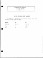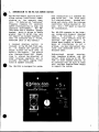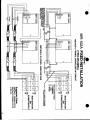
1
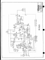
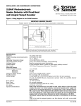
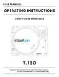
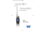
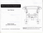
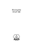
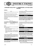
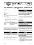
MR-1 02A
Remote Headset
Station
INSTRUCTION
and
SERVICE MANUAL
945 Camelia St. Berkeley, California 94710 510-527-6666
Clear-Com 810033
8/15/88 REV. B
CLEAR-a0M MR-102A REMOE INTERCOM STATION
OPERATION MANUAL
CONTENTS
0
PAGE
Introduction to the Remote Station ..............
System Installation .............................
Headsets ................................
Operating Controls ..............................
Technical Theory of Operation ...................
Parts Listing ................................
Specifications ................................
1
3
4
5
6
7
7
ILLUSTRATIONS
2-Channel Interconnect Wiring ................... 2
MR-102A Mounting Dimensions .................... 3
Headset "Y" Cable ............................... 4
Headset Extension Cord .......................... 4
MR-102A Block Diagram .......................... 6
Schematic ................................
8
ff0
CE.:
While Clear-Com makes every attempt to maintain the accuracy of the
information contained in its product manuaJs, the information is subject to
change without notice.
4
***.4
t i * **
st.
4*
*
t* ********
-i4
t*.-4
-4'144
* :4 4 4 4-4-4-x 4-4-4.t .t
t g:
- *.4
4
4 4
DOCUMENTATION ADDENDUM
MR-102A MANUAL
REV.A
No-;ember 17, 1987
**
-i
i.
t
t.
*4-
t*4
* -4t
4- z ± 4 4-1:
* ******* - 4
4-t****
*
1* 4-:4--f
4*.
**.4-
4*S**
4
* *
*4
J -.* 4 **
- - 4**
471
MIC TO LINE GAIN LEVEL INCREASE
In effectina a 4dB Mic to Line
following changes have been made:
increase i.n gain level,
Change:
At:
To:
lSOR OHM
R5, E8
270K OHM
330pf
C7
i50pf
39f
C8
27?f
the
I.
INTRODUCTION TO THE MR-102A REMOTE STATION
The MR-102A Remote Intercom Station
allows two-way (talk/listen) communicating on
two separate channels.
It features our "contoured"
frequency response for excellent
speech intelligibility in high- and
low-noise environments.
The MR102A works with a standard dynamic
headset, which it drives to levels
greater than 110 dB SPL (the unit
can support two dynamic headsets if
they are connected with a Y-cord,
described later in this manual).
ai
A recessed sidetone control
is
included on the MR-102A front panel.
It enables the operator to
adjust his/her own voice level as
heard in the headset.
The station
also features Visual Call Signalling to attract the attention of
other intercom operators and to
activate the remote paging functions at speaker stations.
W The MR-102A is designed for perma-
nent installation in a standard two
gang outlet box.
The front panel
is a charcoal-brown,
brushed aluminum wall plate, with the intercom
electronics module mounted on the
back. Only 1.75" depth is required
for installation.
The MR-102A connects to the intercom system with standard shielded
cable.
It provides a clearlylabelled, 5-pin terminal strip for
intercom
and power input.
In
places where conduit is present, or
where AC interference is not a
problem, you may interconnect stations with unshielded wire or unshielded cable.
Bidirectional
current
sourcing,
high impedance bridging, and low
current drain allow up to 100 MR102A or other headset stations to
be connected over one mile of cable
with one Main Station/Power Supply
to support the system.
_~~~~~
'I_
~~~~~~~~~~~~~~~~~~~~~~~~~~~~~~~~~~~~
o
(a
zml*
a
mZZ<
-,m~~mo,
Z-M
~~
~
0
0~~~~~~~
_
0~~~~~~~
_
wwO.
0
K
wa, 0
OK~~~~~~~n
0
>0
-Ic
z~~~~
>c~~~~~~~~~~~~~~~~~~~~~~~~~O
6
U0
-c
c-
r
~~~~
2~~~~~~~~~~~~~~
r
~~~r
-c~~C)
>A
II.
*
INSTALLATION OF THE MR-102A
The MR-102A connects to the intercom system via a five-screw terminal strip (designated on the Schematic as "H-1i). While making connections, refer to the stick-on
label adjacent to the
terminal
strip on the back of the MR-102A
panel; it identifies each pin by
number and assignment, as shown
below:
C-H. I
CH 1+30D
assignments:
1--Chassis Ground
2--Intercom Audio/Channel A
3--Intercom Audio/Channel B
4--DC, +30 volts
5--Common
-chassis
1;
v A
@ BI
\J_
4 s2 3 1
Designed for permanent installation, the MR-102A mounts readily in
a standard 2-gang electrical outlet
box, minimum depth 1-3/4". Refer to
Figure 1, Interconnect Wiring, when
deciding how to install the unit.
*
To prevent ground loops and buzzes,
the common terminal (pin 5) should
NEVER
be directly connected to
ground (pin 1).
Use conduit or a separate wire to interconnect two or more MR-102A
panels.
If you plan to use only one channel
on the MR-102A, disable the Channel Select switch by jumping Channels A and B together on the connector block, and hook the intercom
audio line to either terminal.
After preparing a surface for installation,
route standard twoconductor, shielded cable from a
Main Station/Power Supply output
connector to the MR-102A's
location.
Connect wire to the terminals according to the following pin
A diode in the DC input of each
Remote Station protects the circuitry against miswiring in the interconnect cables.
The Remote Station bridges the terminated audio
line with approximately 20k ohms.
MP-102
MOUNTING DIMENSIONS
.3.6
Figure2
X
OVERALL,
1 375
MIN/MUM DEPTH,
'75'
3
III. HEADSErS
The MR-102A provides a 4-pin, male
XLR connector for a dynamic headset.
The
MR-102A drives two dynamic
headsets with only a slight reduction in level.
Clear-Corn can supply you with Model YC-100 "Y" Adap-
ter Cable, which allows you to plug
two headsets into the one 4-pin
connector on the front panel.
Its built-in headset amplifier can
drive one headset to levels greater
than 110 dB SPL. The mic preamp
automatically shuts off when the
headset is disconnected, thereby
eliminating hum pick-up and extraneous noise.
The headset connector pin-out
signment is:
Pin 1: Mic Ground
Pin 2: Mic Hot
Pin 3: Headphone Ground
Pin 4: Headphone Hot
Alternately, you may construct your
own Y-cable; we recommend you use
Belden 8416 (2-conductor, 25 gauge)
or Belden 8734 (3-conductor,
22
gauge); see Figure 3.
as-
If desired, you may construct an
extension cord for your dynamic
headset., using the same cable specified above (see Figure 4).
Limit
the extension to 15 feet or less;
greater lengths lead to possible
capacity coupling between the mic
signal and the headset
signal,
which would cause oscillation or a
loss in frequency response.
To assure proper level and performance, the dynamic headset should
have the following characteristics:
Microphone type:
dynamic
Impedance:
150-250 ohms
Output level:
-55 dB
Headphone type:
dynamic
Output impedance:
300-2000 ohms
Figure 3: HEADSET r-CABLE CONNECTIONS
A4F
&
_xt
A
PIN 1: UIC GROUND
PIN 2: MIC HOT
PIN 3: HEADPHONE GROUND
Pin 4: HEADPHONE HOT
PAW
CAUTION: DO NOT CONNECT
MIC GROUND & HEADPHONE
GROUND TOGETHER
A4F
43
A4M
Figure 4: HEADSET EXTENSION CORD
is
OR
LESS
A4M
IV.
MR-102A OPERATING CONTROLS
S A/B Chan.
This
Select
two-position toggle switch selects which channel will be used for
communicating.
Volume
This knob adjusts the listen-level in the headset.
Sidetone Adj.
The MR-102A provides a Sidetone control which enables the operator to
adjust the level of his/her voice as heard in the headset, allowing up
to 35 dB reduction of acoustical pick-up. You need only adjust the
sidetone once (if at all), even if other stations subsequently join or
leave the intercom system. Adjusting the sidetone does not affect the
level of incoming or outgoing signals.
The sidetone control is inside an unmarked hole located above the
Volume control. The sidetone adjustment is accomplished with a smallbladed screwdriver. At the factory, Clear-Com sets the sidetone to be
approximately 6 dB lower than the incoming signals.
Adjust sidetone in the following manner:
*
1) plug in headset
2) turn on mic
3) turn up volume all the way
4) insert screwdriver through front panel hole and engage the slot on
the internal trimpot
5) begin talking while slowly turning the screwdriver. When you can
barely hear yourself, you'll have found the null point.
Off/Mic-On/Call
This 3-position toggle switch provides three functions. In the up
position, the mic in your headset is "off". In the middle position, the
mic is on.
The third position, Call, is associated with the Visual Signal Circuitry that's standard on Clear-Con equipment. It allows the intercom
user to attract the attention of operators who have removed their
headsets. Signalling other stations is accomplished by momentarily
pressing the switch down to the Call position. Signalling follows the
position of the Channel Select switch; for instance, if you are on
Channel A, signalling activates the call lights on all stations that
are assigned to that channel.
*
Call Light
The amber lamp on the MR-102A will light up when another station (which
is using the same channel as the MR-102A) activates the Call circuit,
or when you are calling other stations. If it is necessary to replace
the light, unscrew the lens cap and remove the bulb; its replacement is
a #387 bulb.
V. THEORY OF OPERATION
incorporates ClearThe MR-102A
Com's high-impedance bridging meth-
od, so it connects to the system
without taking appreciable power
from the line. This enables up to
100 MR-102A's to be connected in
one system with only a 6 dB loss in
level.
Each Remote Station consists of 3
basic circuits: the listen circuit,
the talk circuit (including sidetone) and the signalling circuit.
In the LISTEN circuit, signals from
the line and the mic pre-amp go to
the buffer amp (where signals are
amplified 10 dB), then to the volume control, and then to the headset amp for a final 38 dB of gain.
Current-limiting in the headset amp
protects it from shorts.
In the TALK circuit, signals from
the mic are amplified 37 dB by a
Preamplified
low-level pre-amp.
signals are sent to the audio line
(where they're attenuated by 17
dB) and to the line buffer amp. The
line buffer feeds part of the signal back to the bridging circuit,
raising the line impedance to 20k
When the mic is turned off,
ohms.
the mic pre-amp gain is reduced to
unity, reducing any noise in
input circuitry by 30 dB.
The SIDETONE control works by injecting a portion of the audio
signal from the mic into the buffer
The mic pre-amp signal feeds
amp.
through the sidetone volume control
and to the inverting input of the
Cancellation occurs
buffer amp.
when the mic signal on the line and
the signal from the sidetone control are mixed into the buffer amp.
The cancellation can be varied from
full on to a 35 db null.
The visual CALL SIGNAL is accomplished by impressing a DC voltage
on the audio line. Pressing "Call"
turns on a transistor, applying
about 11 volts to the audio line.
This voltage goes to all Stations
on the same channel, where the DC
is detected by a high gain amp that
turns on the Call light. The callreceive circuit requires only 4
volts from the line to turn on the
The 7-volt difference belight.
tween the send and receive voltages
assures positive signalling, even
Various capaon very long lines.
citors block DC call voltages from
entering the amp circuits.
MR-102A BLOCK DIAGRAM
sncn
CO'4.ECTOR>
61
AOUTlv
the
VI.
VII.
.
PARTS LISTING
Part #
Description
710030
Printed Circuit Module
1
210013
Connector, dynamic headset
1
J3
240014
Volume knob, 3/44" black
1
P2
390000
390001
Lamp cover, amber
Light bulb, #387
1
IA
510004
Switch, toggle, 3-pos
1
Si
510040
Switch, toggle, 2-pos
1
S2
Qty.
Schematic Ref. Des.
-a
MR-102A SPECIFICATIONS
AMPLIFIER DESIGN
Solid-state, integrated circuit amps (which include a mic preamp, headset power
amp and signalling circuit). Current-limited with short-circuit & reverse polarity protection.
MIC PREAMPLIFIER
Frequency Response: 250 Hz-12k Hz,
contoured to enhance
intelligibility
Mic Input Impedance:
200 ohms
Mic Preamp Gain:
37dB
Max. Input before Clipping: -34dBv*
HEADPHONE AMPLIFIER
Freq. Response:
150-18k Hz, 42 dB
Load Impedance Range: 300-2000 ohms
Output Level:
+20 dBm, 26v p-p
@ 600 ohms
Headset Level:
>110 dB with
standard Clear-Com headsets
Distortion:
0.2% THD at 1k Hz
Amplifier Gain:
38dB
GENERAL SPECS
Line Level:
-15dBv max*
Sidetone Adj.: 35dB null to full on
Call Voltage: 11 VDC on audio line
Call Light Sensitivity:
4 volts
Signal-to-Noise:
75dBv*
Equivalent Input Noise:
12ldBv*
Station Bridging
Impedance:
20k ohm (200-10k Hz)
Power Required:
10 ma quiescent,
15 ma talking
55 ma signalling
Voltage Range: 12-32v, 28v nominal
CONNECTORS
Dynanic Headset:
4-pin, XLR, male
Line:
5-screw terminal block
'OdBv is referenced to 0.775 volts RIS.
PHYSICAL CHARACTERISTICS
Dimensions:
4.5" (11.3 cm) square
Rear Depth:
1.75" (4.38 cm)
Weight:
7.25 oz. (.21 kg)
=N m
N
VIE
i3q
s
o 9-Mt
Y
o>a
-
uB-~~~~~~~~~~~~~~~~
CD0a
+ro
t)
sr
gN
,C
Z
W~cc
1X~~~~~~~~~~~i; S~~~~~
O
ffi
<r
1
4
j f 0
'
e
_