1
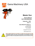
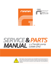
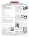
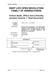
Components and Service Manual Transfer Pump 2:1 1.8 Revision 01/04/15 Ref. NR-00061-ENG Before installing and operating the pump, carefully read the technical and safety documentation in this manual. Special attention should be paid to the information in order to know and understand the handling and conditions of use of the pump. All of the information is aimed at enhancing user safety and avoiding possible faults due to incorrect use of the pump. Service and Components Manual GUARANTEE GARRAF MAQUINARIA, S. A. (hereinafter “GAMA”) grants this Limited Guarantee to the original buyer (hereinafter the “Client”) for the unit and the original accessories given with the unit (hereinafter the “Product”) against any fault in the design, materials or manufacture of the Product at the time of the first purchase by the user and for a duration of two (2) years thereafter. If during the guarantee period and under normal conditions of use, the Product should fail to work correctly due to defects of design, material or manufacture, the authorised distributor of the country where the GAMA Product or technical assistance service has been purchased shall repair or replace the Product in accordance with what is established in the following CONDITIONS a) The validity of this guarantee will be subject to the presentation of the original invoice issued by the GAMA authorised distributor for the sale of the Product along with the Product handed over for repair or replacement, which must show the date of purchase and the serial number. GAMA reserves the right to refuse to give the guarantee service when the indicated data fail to appear on the invoice or have been modified after the purchase of the Product. b) The repaired or replaced Product will continue to maintain the original guarantee for the time remaining until the end of the guarantee or for three (3) months from the repair date, if the remaining period of the original guarantee were shorter. c) This guarantee will not be applied to the faults in the Product caused by its faulty installation, the natural wear and tear of the components, any use other than that considered normal for this Product or which should fail to strictly comply with the instructions of use provided by GAMA; due to accident, carelessness, adjustments, alterations or modifications of the Product not authorised by GAMA or due to the use of accessories, heating devices, pumping equipment and/or dispensers that have not been approved or manufactured by GAMA. d) The guarantee applicable to the components and accessories forming part of the Product and which have not been made by GAMA will be limited to the guarantee offered by the original manufacturer thereof. GAMA WILL NOT RECOGNISE ANY EXPRESS ORAL OR WRITTEN GUARANTEES OTHER THAN THIS PRINTED LIMITED GUARANTEE. ALL IMPLICIT GUARANTEES, INCLUDING, WITHOUT LIMIT, ADAPTATION FOR A SPECIFIC USE, ARE SUBJECT TO THE DURATION OF THIS WRITTEN GUARANTEE. GAMA DOES NOT ASSUME ANY KIND OF COMMITMENT OR RESPONSIBILITY FOR ALL POSSIBLE DAMAGE OR EXPENSE CAUSED BY FAULTS IN THE OUTPUT OF THE PRODUCT, ITS WORKING OR THE DISPENSING OF MATERIAL THROUGH THE PRODUCT, INCLUDING, WITHOUT LIMITATION, ALL EXPENSES CAUSED BY DAMAGE TO PEOPLE OR PROPERTY. EQUALLY, GAMA WILL IN NO CASE ACCEPT LIABILITY FOR THE LOSS OF SPECULATIVE PROFITS OR COMMERCIAL LOSSES. ALL REPAIRS OR REPLACEMENT OF FAULTY PRODUCTS WILL CONSTITUTE THE COMPREHENSIVE FULFILMENT OF GAMA'S OBLIGATIONS WITH RESPECT TO THE CLIENT. GAMA DOES NOT IN ANY WAY GUARANTEE THE SUITABILITY OR APTITUDE OF ITS PRODUCT FOR ANY PARTICULAR PURPOSE OR APPLICATION. All of the information provided on components which have not been manufactured by GAMA and which is based on reports received from the original manufacturer, though considered precise and reliable, is provided without any guarantee or responsibility of any explicit or implicit kind. All concession, sale or financial leasing of the Product by GAMA in no case explicitly or implicitly constitutes any authorisation, acceptance or concession for the use of any rights or patents, nor does it encourage, nurture or back their infringement. The restrictions on the guarantee suppose no limitation on the legal rights of the consumer established in applicable national legislation, nor do they affect any rights derived from the bargain and sale agreement between the consumer and supplier. 2/38 1.8 Revision http://www.gamapur.com Ref. NR-00061-ENG Service and Components Manual All of the information provided in this Service Manual has been included in the confidence that it is true, although it does not constitute any responsibility or implicit or explicit guarantee. GAMA reserves the right at any time and without prior warning to make all improvements and modifications necessary to this Service Manual, in order to rectify any possible typographical errors, increase the information contained or insert the changes caused to the characteristics and performance of the unit. SAFETY AND HANDLING This chapter contains important information regarding the safety, handling and use of the transfer pump. Before installing and starting up the pump, carefully read all the technical and safety documentation included in this manual. Special attention should be paid to the information in order to know and understand the handling and conditions of use of the pump. All of the information is aimed at enhancing user safety and avoiding possible faults due to incorrect use of the pump. A WARNING! establishes information to alert on a situation that might cause serious injuries if the instructions are not followed. A PRECAUTION! establishes information that indicates how to avoid damage to the pump or how to avoid a situation that could cause minor injuries. A NOTE is relevant information on a procedure being carried out. Careful study of this manual will help you to become more acquainted with the pump and the procedures. Following the instructions and recommendations here will reduce the potential risk of accidents in installing, using or maintaining the pump, and will give you the problem-free operation for a longer time, greater output and the possibility of detecting and resolving problems quickly and simply. Keep this Service Manual for future consultation of useful information at all times. If you lose the manual, ask for a new copy from your local GAMA distributor or make direct contact with Garraf Maquinaria, S. A. These instructions must be complemented by the national requisites in order to prevent accidents and protect the environment. 3/38 1.8 Revision http://www.gamapur.com Ref. NR-00061-ENG Service and Components Manual When working with the pump, it is essential to dress suitably and use personal protective equipment, including the unlimited use of gloves, protective goggles, safety footwear and face masks. Use breathing equipment when working with the pump in enclosed or insufficiently ventilated atmospheres. The introduction and monitoring of safety measures must not be limited to those described in this manual. Before starting to use the pump, a rigorous analysis must be made of the risks derived from the products to be dispensed, the type of application and the working environment. To prevent all possible body harm caused by incorrect handling of the raw materials and solvents used in the process, carefully read the safety information provided by your supplier. Deal with all waste according to each country's current regulations. The high speed of the product flowing through the conducts might cause static electricity shown by small shocks and sparks. The pump should be grounded. WARNING! In potentially explosive atmosphere, the ground connection must be made before the pump is brought into operation. To avoid damage caused by the impact of pressurized fluids, do not open any connection or perform maintenance work on components subject to pressure until the pressures have been completely eliminated. Use suitable protection when operating, maintaining or remaining in the operating area of the pump. This includes, but is not limited to, the use of masks, protective goggles, gloves, shoes and safety clothing. Do not touch the sleeve of the pneumatic motor. The air decompression that drives the piston cools the surface considerably after a few minutes of operation, which might cause freezing in contact with the skin. Use gloves or allow the surface to warm in all maintenance work. To prevent serious harm by crushing or loss of limbs, do not work with the unit without the safety protections duly installed on all moving parts. Make sure that all of the safety protections are correctly fitted after all repair or maintenance work. 4/38 1.8 Revision http://www.gamapur.com Ref. NR-00061-ENG Service and Components Manual TYPICAL INSTALLATION Figure 1. Typical Installation in a G-50 H with recirculation. 5/38 1.8 Revision http://www.gamapur.com Ref. NR-00061-ENG Service and Components Manual DESCRIPTION The GAMA 2.25:1 pump is a pneumatically-driven, double effect, alternating pump used for moving liquids with a maximum viscosity of 2,000 mPas. The compressed air causes the alternating rising and falling movement in the pneumatic piston, which is transmitted by means of a connection rod to the plungers of the upper and lower chamber of the pump, thereby sucking and driving the fluid. The fluid output pressure is 2.25 times higher than the air pressure causing the movement of the pneumatic piston. All materials coming into contact with the fluid are made in stainless steel of the highest quality. 6/38 1.8 Revision http://www.gamapur.com Ref. NR-00061-ENG Service and Components Manual OPERATION DIAGRAM Figure 2. Operation Diagram 7/38 1.8 Revision http://www.gamapur.com Ref. NR-00061-ENG Service and Components Manual PNEUMATIC MOTOR OPERATION Process of reversing the movement of the pneumatic piston. The pump movement is reversed thanks to a floating mechanism in the pneumatic piston. When it rises, the air in the lower chamber of the piston pushes it upwards, the air in the upper chamber is decompressed and released from the motor through the piston shaft. When the piston makes contact with the upper spring, a valve is opened inside it that allows the air entering the motor to go straight into the upper chamber, thus pushing the piston down. When the piston makes contact with the lower spring, the internal valve is closed and the air pressure pushes the piston upwards, whereas the pressurized air in the upper chamber is released through the piston shaft. PUMPING MECHANISM OPERATION Up stroke (see Figure 2 left side) The lower plunger of the pump rises and keeps the valve of the upper plunger closed, pushing the product in the upper chamber to the pump outlet (volume “B”). The depression produced in the lower chamber of the plunger in the rising movement opens the ball of the lower valve, thus sucking the fluid in from the vessel (volume “A”). Down stroke (see Figure 2 right side) The lower plunger of the pump moves downwards and exerts pressure on the lower ball, closing it mechanically. The same downwards movement opens the ball of the upper valve, allowing the fluid from volume “A” into the intermediate chamber and the surplus material (half of volume “A”) is moved to the pump outlet (volume “C”). N.B.: The pump only sucks material when it rises (Volume “A”), but drives material when it rises (Volume “B”) and when it falls (Volume “C”). Volume “A” = Volume “B” + Volume “C”. 8/38 1.8 Revision http://www.gamapur.com Ref. NR-00061-ENG Service and Components Manual TECHNICAL SPECIFICATIONS Pressure ratio: _________________________________2.25:1 (@ 7 bar air – 15.7 bar product) Maximum fluid pressure: _________________________________________________22.5 bar Maximum air inlet pressure: ________________________________________________10 bar Maximum fluid temperature: _________________________________________________85ºC. Maximum outlet volume: ________________________________________________20.8L./min Piston movement: __________________________________________________101.6mm (4”) 3 Suction volume (only rising): _______________________________________________206cm 3 3 Transfer volume (by stroke/cycle): ____________________________________103cm /206cm Volume of consumed air (by stroke/cycle) @ 7 bar: ____________________________1.6L/3.2L N. cycles to transfer 1 litre: ___________________________________________________4.85 Weight: ________________________________________________________10.5Kg (23.15lb) Air connection: _________________________________________________________1/4”NPT Product outlet connection: ________________________________________________3/4”NPT Noise level @ 7 bar (air): ________________________________________________85 (A) dB DIMENSIONS PU-04002 mod. 54” (1371.6) PU-04003 mod. 46” (1168.4) A. 1371.6 mm (54") 1168.4 mm (46”) B 876 mm (34.5”) 673 mm (26.5”) C 244.5 mm (9.62”) 244.5 mm (9.62”) D 842 mm (33.15”) 639 mm (25.16”) Figure 3. General Dimensions 9/38 1.8 Revision http://www.gamapur.com Ref. NR-00061-ENG Service and Components Manual KITS LIST OF TRANSFER PUMPS Table 1. Kits List of Transfer Pumps According to model Unit, Length & Pump Size PU-04002 (54” Pump) PU-04003 (46” Pump) Hoses Length 3,5 mts. Hoses Length 5 mts. Hoses Length 3,5 mts. Hoses Length 5 mts. G-140 H G-250 H G-30 H G-50 H NE-00040 NE-00040-01 NE-00040-02 - G-125 A G-200 A VR NE-00041 NE-00041-03 - - - - - COMPACT ES-125 A NE-00041-01 EASY-SPRAY (without tanks) NE-00041-02 10/38 1.8 Revision http://www.gamapur.com Ref. NR-00061-ENG Service and Components Manual TRANSFER PUMPS KITS Table 2. Transfer Pump Kit NE-00040, Parts List PU-04002 Standard Transfer Pum Assy 2x Machine Connection kit for air compressor. For hydraulic machines except for VR model: MA-00034 1x machine / 1x 2 Pumps Air supply connection kit for hydraulic machines except for VR model: MA-00035 1x machine / 1x 2 Pumps Product hose: MA-00026 2x machine / 1x Pump Product outlet connection: RA-00212 2x machine / 1x Pump 11/38 1.8 Revision http://www.gamapur.com Ref. NR-00061-ENG Service and Components Manual Table 3. Transfer Pump Kit NE-00040-01, Parts List PU-04002 Standard Transfer Pum Assy 2x Machine Connection kit for air compressor. For hydraulic machines except for VR model: MA-00034 1x machine / 1x 2 Pumps Air supply connection kit for hydraulic machines except for VR model: MA-00035-1 1x machine / 1x 2 Pumps Product hose: MA-00026-01 2x machine / 1x Pump Product outlet connection: RA-00212 2x machine / 1x Pump 12/38 1.8 Revision http://www.gamapur.com Ref. NR-00061-ENG Service and Components Manual Table 4. Transfer Pump Kit NE-00040-02, Parts List PU-04003 Short Transfer Pum Assy 2x Machine Connection kit for air compressor. For hydraulic machines except for VR model: MA-00034 1x machine / 1x 2 Pumps Air supply connection kit for hydraulic machines except for VR model: MA-00035 1x machine / 1x 2 Pumps Product hose: MA-00026 2x machine / 1x Pump Product outlet connection: RA-00212 2x machine / 1x Pump 13/38 1.8 Revision http://www.gamapur.com Ref. NR-00061-ENG Service and Components Manual Table 5. Transfer Pump Kit NE-00041, Parts List PU-04002 Standard Transfer Pum Assy 2x Machine Connection kit for air compressor. For pneumatic machines and VR model: MA-00032 1x machine / 1x 2 Pumps Air supply connection kit for pneumatic machines and for VR model: MA-00033 2x machine / 1x Pump Product hose: MA-00026 2x machine / 1x Pump Product outlet connection: RA-00212 2x machine / 1x Pump 14/38 1.8 Revision http://www.gamapur.com Ref. NR-00061-ENG Service and Components Manual Table 6. Transfer Pump Kit NE-00041-01, Parts List PU-04002 Standard Transfer Pum Assy 2x Machine Connection kit for air compressor. For pneumatic machines and VR model: MA-00032 1x machine / 1x 2 Pumps Air supply connection kit for pneumatic machines and for VR model: MA-00033 2x machine / 1x Pump Product hose: MA-00026 2x machine / 1x Pump Product outlet connection: RA-00212 2x machine / 1x Pump Air Distributor: RA-00095 2x máquina / 1x bomba NE-00068 1x máquina / 1x 2 bombas RA-00054 1x máquina / 1x 2 bombas 15/38 1.8 Revision http://www.gamapur.com Ref. NR-00061-ENG Service and Components Manual Table 7. Transfer Pump Kit NE-00041-02, Parts List PU-04002 Standard Transfer Pum Assy 2x Machine Connection kit for air compressor. For pneumatic machines and VR model: MA-00032 1x machine / 1x 2 Pumps Air supply connection kit for pneumatic machine Easy Spray: MA-00035-3 1x machine / 1x 2 Pumps Product hose: MA-00026 2x machine / 1x Pump Product outlet connection: RA-00212 2x machine / 1x Pump Air Connection for Easy Spray: RA-00135 RA-00109 RA-00048 16/38 1x machine / 1x 2 Pumps 1x machine / 1x 2 Pumps 2x machine / 1x Pump 1.8 Revision http://www.gamapur.com Ref. NR-00061-ENG Service and Components Manual Table 8. Transfer Pump Kit NE-00041-03, Parts List PU-04002 Standard Transfer Pum Assy 2x Machine Connection kit for air compressor. For pneumatic machines and VR model: MA-00032 1x machine / 1x 2 Pumps Air supply connection kit for pneumatic machines and for VR model: MA-00033-4 2x machine / 1x Pump Product hose: MA-00026-01 2x machine / 1x Pump Product outlet connection: RA-00212 2x machine / 1x Pump 17/38 1.8 Revision http://www.gamapur.com Ref. NR-00061-ENG Service and Components Manual INSTALLATION Reception Although all precautions are taken in packing and sending in the factory, the goods must be checked when they are received. Make sure that all the parts and accessories on the remittance are correct and have not been damaged in transport. In the package, along with the pump you must receive 2 tools for tightening the stop valves (HT00077). Storage If the pump is going to be stored before installation, leave it in a clean and dry place. Do not remove the protection caps from the connections to prevent dirt from entering the pump. Assembly 1. Screw the clip of the transfer pump onto the drum. Make sure the corresponding seal is included. Insert the pump with its seal into the clip and the drum, close the two staples to hold the pump to the clip. 2. Screw the 1/4”NPT-1/4”BSP thread adapter and the ball valve on to the pump, placing sealing paste or teflon tape on the threads to ensure that the unit is properly sealed. Make sure that the ball valve is closed. Do not connect the network air supply yet. N.B.: The thread adapter and the ball valve are not supplied with the pump. These parts are included in Transfer Pump Kits (See Table 1). 18/38 1.8 Revision http://www.gamapur.com Ref. NR-00061-ENG Service and Components Manual 3. Screw the RA-00012 product outlet connector on the 3/4”NPT thread of the pump. N.B.: The connector is not supplied with the pump. This Part is included in Transfer Pump Kits (see Table 1) The high speed of the product flowing through the conducts might cause static electricity shown by small shocks and sparks. The pump should be grounded with a wire connected to mass on the fixture provided. WARNING! In potentially explosive atmospheres or with flammable products, the ground connection must be made before the pump is brought into operation. 4. A wire may be used with a peeled end, which is inserted through the protection in the drill hole provided and fixed with the bolt (figure on the left), or, if you prefer, a wire may be used with a terminal for M5 bolt, which is fixed as shown in the drawing (figure on the right). 19/38 1.8 Revision http://www.gamapur.com Ref. NR-00061-ENG Service and Components Manual 5. Screw MA-00026 product hose on the pump connection and the machine valve. Place sealing paste or Teflon tape on the threads to ensure that the unit is sealed. N.B.: The MA-00026 hose is not supplied with the pump. This Part is included in the Transfer Pump Kits (see Table 1). 6. Open the ball valve on the machine inlet. 7. Now connect the air supply hose and open the air valve on the machine to start the transfer pump. Do this by slowly opening the valve until the pump piston begins to move. Use the valve opening to control the speed of the pump. The transfer pump is used to transfer both isocyanates and polyols. However, once one of the two products has passed through it, it is recommendable to identify it by marking it clearly and visibly in order to know which product it contains or which product has been transferred. Any mistake putting it into the wrong product drum or attaching the wrong hose connection would contaminate the pump and render it useless. Never allow the pump to continue working without product, as this could rapidly damage the seals. Stop the pump if you see that it accelerates fast or moves too rapidly. 20/38 1.8 Revision http://www.gamapur.com Ref. NR-00061-ENG Service and Components Manual N.B.: For the installation of the kit NE-00041-01, mount the items NE-00068 (1x), RA00054 (1x) and RA-00095 (2x) inserted in the machine after the air filter as the following figures show. Figure 4. Compact 21/38 ES-125 A Assy Figure 5. Easy-Spray 1.8 Revision http://www.gamapur.com Assy Ref. NR-00061-ENG Service and Components Manual STOPPING METHOD When you want to stop the pump, shut off the air supply with the ball valve, and then disconnect the air connector. If the pump is going to be shut down for a short time, it is best not to empty it as this prevents air and damp from entering and avoids any contamination. If the pump is to be shut down for a long period of time, it must be completely emptied of product and carefully and thoroughly cleaned with a cleaning agent (DOP). It must then be stored in a clean, dry place. WARNING! Do not touch the sleeve of the pneumatic motor. The air decompression that drives the piston cools the surface considerably after a few minutes of operation, which might cause freezing in contact with the skin. Use gloves or allow the surface to warm in all maintenance work. CLEANING Cleaning is understood as the cleaning that has to be done before using a different product or when a long period of inactivity is expected for the pump and the metering unit. Follow the recommended procedure in the order indicated to perform the cleaning when you have to change the components of the system: a) Place two drums of DOP cleaning agent near the metering unit. b) Remove the gun and leave the coupling block connected to the hoses. c) Remove the transfer pumps from the drums of product and place them in the drums of DOP cleaning agent. d) Place a vessel under the coupling block to gather up the products contained inside the machine. e) Open the taps of the coupling block and start up the metering unit. Make sure the machine product inlet valves and the air inlets valves to the pumps are open. f) Allow the products to come out until you see that only DOP cleaning agent comes out free of impurities. g) Close the taps of the coupling block and stop the metering unit. h) Close the air inlet taps to the pumps and place the transfer pumps in the drums of the new products. 22/38 1.8 Revision http://www.gamapur.com Ref. NR-00061-ENG Service and Components Manual i) Place a vessel under the coupling block to collect the DOP cleaning agent. j) Open the taps of the coupling block and start up the metering unit. k) Open the air inlet valves to the pumps. m) Allow DOP cleaning agent to come out until you see that only the new products come out. n) When the products come out without the contamination produced by the effect of the DOP cleaning agent, the cleaning process is complete and you can proceed as normal. If a long period of inactivity is expected, it is advisable to suck in DOP cleaning agent and leave it inside the pump. It must then be stored in a clean, dry place. N.B.: Keep all hazardous fluids in suitable containers. These products have to be eliminated according to the current laws of each country. 23/38 1.8 Revision http://www.gamapur.com Ref. NR-00061-ENG Service and Components Manual DISMANTLING AND MAINTENANCE WARNING! Before dismantling the pump or carrying out maintenance on it, disconnect the air supply and depressurise the pump. N.B.: All of the threads of the different components in the pump are tightened clockwise. N.B.: If you are going to replace a kit of seals, replace all of those included in the kit supplied. Although there may seem to be seals in a good state, the combination of new seals with seals that have been worn by the accumulated work can cause the pump to work badly. 1. To facilitate the pump dismantling and assembly, place it in a vice, holding it by the triangular base of the body, having previously removed the polycarbonate protections. Before fixing the pump in a vice, remember to remove the three polycarbonate protections. 24/38 1.8 Revision http://www.gamapur.com Ref. NR-00061-ENG Service and Components Manual 2. Unscrew the pump suction valve using a 42mm or 1 5/8” spanner (not supplied). Use a belt spanner (not supplied) to loosen the valve, if necessary, placing it as close as possible to the end of the pipe in order to avoid deformations. The pneumatic cylinder contains pressurised air that must be removed before dismantling. All failure to observe this step can cause serious injuries. 3. Depressurise the pneumatic cylinder as follows: Disconnect the air supply. Open the air inlet valve. Loosen the purging screw of the pneumatic cylinder on the top cover. Now you can dismantle the pump. 4. hold the air sleeve and unscrew it from the lower cover. 25/38 1.8 Revision http://www.gamapur.com Ref. NR-00061-ENG Service and Components Manual 5. Use the two 8 mm (or 5/16”) pins for unscrew the lower chrome guide of the plunger. WARNING! Do not use the hexagonal geometry of the upper nut of the plunger to loosen and unscrew the rod as this can cause irreparable damage to the plunger interior mechanism. 6. Remove the pin fixing the piston and the rod. 26/38 1.8 Revision http://www.gamapur.com Ref. NR-00061-ENG Service and Components Manual 7. Loosen the nut holding the stop valve, push the rod and remove the lower plunger from the pump through the lower suction sleeve. 8. Inspect the seals and replace as necessary. Pay special attention to the direction of the seals when fitting. 9. Lubricate and fit all parts in reverse order to the process described above. 27/38 1.8 Revision http://www.gamapur.com Ref. NR-00061-ENG Service and Components Manual TROUBLESHOOTING Problem Cause The supply air pressure is very low Check the air supply line and increase the diameter of the supply pipe. Increase the inlet pressure. The supply air flow is insufficient Check the air supply line and increase the diameter of the supply pipe. Open the air inlet valve completely. Worn pneumatic piston seals Replace all worn seals Lack of product Add product Lower valve worn or partially obstructed Remove the valve, clean it and replace all worn parts as necessary Upper valve worn or partially obstructed Remove the valve, clean it and replace all worn parts as necessary Lower valve worn or partially obstructed Remove the valve, clean it and replace all worn parts as necessary Product outlet line obstructed Disconnect the outlet hose, feed the product with minimum pressure and check whether the flow increases The supply air pressure is too low Increase the air pressure. Upper chamber piston seal loose or worn Tighten or replace the seal The pump does not work The pump works too fast The pump works, but not enough product comes out The pump loses product above the upper chamber 28/38 Solution 1.8 Revision http://www.gamapur.com Ref. NR-00061-ENG Service and Components Manual COMPONENT IDENTIFICATION Figure 6. General Diagram. 29/38 1.8 Revision http://www.gamapur.com Ref. NR-00061-ENG Service and Components Manual Figure 7. Details of Diagram of Upper Plunger (Pneumatic). Figure 8. Details of Diagram of Lower Plunger. 30/38 1.8 Revision http://www.gamapur.com Ref. NR-00061-ENG Service and Components Manual Table 9. List of Components Pos. Reference Qty. Suction Valve Unit (includes Pos.1.1 to 1.4) PU-04002-009 1 1.1 Valve Body PU-04002-010 1 1.2 Ball PU-04000-090 1 1.3 Pin TN-00308 1 1.4 O-ring (*) OR-00107 1 1 Description 2 Pump Base seal (*) PU-04000-040 1 3 Pump Body Unit (includes Pos.3.1 and 3.2) PU-04002-001 1 3.1 Pump Body PU-04002-002 1 3.2 Pump Body Interior Sleeve PU-04002-008 1 OR-00009 1 4 O-ring (*) 5 Pump Suction Sleeve See Table 10 1 6 Pump Plunger Cover PU-04000-053 1 7 Pump Lower Plunger Guide (*) PU04000-067 1 8 Lower Pump Lip Seal (*) PU-04000-070 1 9 Ball PU-04000-090 1 10 O-ring (*) OR-00107 1 11 Pump Body Unit (includes Pos.11.1 to 11.6) PU-04002-031 1 11.1 Pump Rod PU-04002-032 1 11.2 Lower Plunger Head PU-04002-033 1 11.3 Pump Upper Stop Valve Plunger PU-04002-034 1 11.4 O-ring (*) OR-00114 1 11.5 Pin TN-00302 1 11.6 Pin TN-00303 1 11.7 Washer TN-00145 1 11.8 Lock Nut TN-00165 1 12 Pump Upper Plunger Stop Valve (*) PU-04000-069 1 13 Stop Valve Nut PU-04000-059 1 14 Trap TN-00304 1 31/38 1.8 Revision http://www.gamapur.com Ref. NR-00061-ENG Service and Components Manual Pos. Reference Qty. Pump Flange Unit (includes Pos.15.1 to 15.5) See Table 11 1 15.1 Pump Coupling Body See Table 11 1 15.2 Pump Base seal (*) PU-04000-040 1 15.3 Pump Flange Staple PU-04002-040 2 15.4 Round Head Bolt TN-00020 4 15.5 Washer TN-00139 4 15 Description 16 Pump Outlet Body Cover PU-04002-012 1 17 Test Seat Seal PU-04000-068 1 18 Bolt TN-00306 3 19 Bolt TN-00248 1 20 Air Cylinder Stay PU-04000-063 3 21 Pneumatic Plunger Unit (includes Pos.21.1 to 21.12) PU-04002-018 1 21.1 Pneumatic Plunger Body PU-04002-019 1 21.2 O-ring (*) OR-00108 3 21.3 Plunger Lower Disk PU-04002-020 1 21.4 O-ring (*) OR-00109 1 21.5 Upper Plunger Disk Unit (includes Pos. 21.5.1 to 21.5.4) PU-04002-021 1 21.5.1 Upper Disk (#) PU-04002-022 1 21.5.2 Plunger Interior Core (#) PU-04002-023 1 21.5.3 Upper Plunger Stop (#) PU-04002-024 1 21.5.4 Sealing Resin (#) - 1 OR-00110 1 PU-04002-025 3 21.6 O-ring (*) 21.7 Pneumatic Plunger Spacer 21.8 Allen Bolt TN-00285 1 21.9 Pin TN-00307 1 21.10 O-ring (*) OR-00111 1 21.11 Plunger Guide (*) PU-04002-026 1 21.12 Allen Bolt TN-00298 3 22 Lip Seal (*) PU-04002-013 1 23 Stop Valve Lower Support PU-04002-014 1 24 Stop Valve Segment (*) PU-04002-015 3 25 Stop Valve Upper Support PU-04002-016 1 26 Stop Valve Nut PU-04000-061 1 32/38 1.8 Revision http://www.gamapur.com Ref. NR-00061-ENG Service and Components Manual Pos. Description Reference Qty. PU-04002-017 1 OR-00112 1 27 Air Cylinder Base 28 O-ring (*) 29 Cylinder Base Seal (*) PU-04000-081 2 30 Pneumatic Cylinder Sleeve PU-04000-062 1 31 Lower Spring PU-04000-073 1 32 Pneumatic Plunger Shaft Unit (includes Pos.32.1 to 32.2) PU-04002-028 1 32.1 Air Plunger Shaft (#) PU-04002-029 1 32.2 Guide Insert (#) PU-04002-030 1 33 O-ring (*) OR-00113 1 34 Pin TN-00301 1 35 Pneumatic Rod Head PU-04002-027 1 36 Trap TN-00299 1 37 Cylinder Pan Conic Spring PU-04000-072 1 38 Cylinder Pan Unit (includes Pos.38.1 to 38.2) PU-04002-035 1 38.1 Air Cylinder Pan (#) PU-04002-036 1 38.2 Elastic Stopper (#) PU-04002-037 1 39 Air Purge Bolt Seal (*) PU-04000-077 1 40 Air Purge Bolt PU-04000-057 1 41 Rod Protection PU-04002-042 3 42 Protection Bolt TN-00317 3 All parts marked with (*) can be supplied separately or as part of a kit. All parts marked with (#) cannot be supplied separately. Table 10. Variants depending on pump size Size Suction Sleeve Qty. Pump 54” PU-04002 PU-04002-011 1 Pump 46” PU-04003 PU-04002-041 1 N.B.: The 54” and 46” pumps contain the same parts, except for that indicated in Table 10. 33/38 1.8 Revision http://www.gamapur.com Ref. NR-00061-ENG Service and Components Manual Table 11. Pump Flange Unit POS.15 POS.15.1 PU-04002-038 PU-04002-039 PU-04002-038A PU-04002-039A PU-04002-038B PU-04002-039B PU-04002-038C PU-04002-039C PU-04002-038D PU-04002-039D Pump Minimal High of Tank (*) PU-04002 (54”) 858 mm PU-04003 (46”) 655 mm PU-04002 (54”) 843 mm PU-04003 (46”) 640 mm PU-04002 (54”) 793 mm PU-04003 (46”) 590 mm PU-04002 (54”) 748 mm PU-04003 (46”) 545 mm PU-04002 (54”) 688 mm PU-04003 (46”) 485 mm N.B.: The Standard Pumps included the Flange Unit PU-04002-038. If you need another model, please consult with our Marketing Department. (*) The dimensions of the tank can change ±5 mm Table 12. KT-00097 (Pneumatic Plunger Seal Kit) Pos. Description Reference Qty. 21.2 O-ring (*) OR-00108 3 21.4 O-ring (*) OR-00109 1 21.6 O-ring (*) OR-00110 1 21.10 O-ring (*) OR-00111 1 21.11 Plunger Guide (*) PU-04002-026 1 Table 13. KT-00098 (Upper Stop Valve Kit) Pos. Description Reference Qty. 22 Lip Seal (*) PU-04002-013 1 24 Stop Valve Segment (*) PU-04002-015 3 34/38 1.8 Revision http://www.gamapur.com Ref. NR-00061-ENG Service and Components Manual Table 14. KT-00099 (Pump Lower Plunger Kit) Pos. Description Reference Qty. 7 Pump Lower Plunger Guide (*) PU04000-067 1 8 Lower Plunger Lip Seal (*) PU-04000-070 1 Table 15. KT-00100 (Pump Upper Plunger Kit) Pos. Description 11.4 O-ring (*) 12 Pump Upper Plunger Stop Valve (*) Reference Qty. OR-00114 1 PU-04000-069 1 Table 16. KT-00101 (Transfer Pump Seal Complete Kit) Pos. Description 1.4 (10) O-ring (*) 2 (15.2) Pump Base seal (*) Reference Qty. OR-00107 2 PU-04000-040 2 OR-00009 1 4 O-ring (*) 7 Pump Lower Plunger Guide (*) PU04000-067 1 8 Lower Plunger Lip Seal (*) PU-04000-070 1 OR-00114 1 11.4 O-ring (*) 12 Pump Upper Plunger Stop Valve (*) PU-04000-069 1 17 Test Seat Seal PU-04000-068 1 21.2 O-ring (*) OR-00108 3 21.4 O-ring (*) OR-00109 1 21.6 O-ring (*) OR-00110 1 21.10 O-ring (*) OR-00111 1 21.11 Plunger Guide (*) PU-04002-026 1 22 Lip Seal (*) PU-04002-013 1 24 Stop Valve Segment (*) PU-04002-015 3 28 O-ring (*) OR-00112 1 29 Cylinder Base Seal (*) PU-04000-081 2 33 O-ring (*) OR-00113 1 39 Air Purge Bolt Seal (*) PU-04000-077 1 35/38 1.8 Revision http://www.gamapur.com Ref. NR-00061-ENG Service and Components Manual Table 17. List of Complements Description Reference Qty. Tin of Lubriplate Grease 397 g BI-00008 1 Tin of Lubriplate Grease 49 g BI-00009 1 Teflon Sealing Paste 50 ml BI-00016 1 36/38 1.8 Revision http://www.gamapur.com Ref. NR-00061-ENG Service and Components Manual CONTENT Guarantee __________________________________________________________________ 2 Safety and Handling __________________________________________________________ 3 Typical Installation ___________________________________________________________ 5 Description _________________________________________________________________ 6 Operation Diagram ___________________________________________________________ 7 Pneumatic Motor Operation ___________________________________________________ 8 Pumping Mechanism Operation ________________________________________________ 8 Technical Specifications ______________________________________________________ 9 Kits List of Transfer Pumps __________________________________________________ 10 Transfer Pumps Kits ________________________________________________________ 11 Installation_________________________________________________________________ 18 Stopping method ___________________________________________________________ 22 Cleaning __________________________________________________________________ 22 Dismantling and Maintenance_________________________________________________ 24 troubleshooting ____________________________________________________________ 28 Component Identification ____________________________________________________ 29 Content ___________________________________________________________________ 37 Illustrations List ____________________________________________________________ 37 List of Tables ______________________________________________________________ 38 ILLUSTRATIONS LIST Figure 1. Typical Installation in a G-50 H with recirculation. _________________________ 5 Figure 2. Operation Diagram ___________________________________________________ 7 Figure 3. General Dimensions__________________________________________________ 9 Figure 4. Compact ES-125 A Assy _____________________________________________ 21 Figure 5. Easy-Spray Assy ___________________________________________________ 21 Figure 6. General Diagram. ___________________________________________________ 29 Figure 7. Details of Diagram of Upper Plunger (Pneumatic). ________________________ 30 Figure 8. Details of Diagram of Lower Plunger. __________________________________ 30 37/38 1.8 Revision http://www.gamapur.com Ref. NR-00061-ENG Service and Components Manual LIST OF TABLES Table 1. Kits List of Transfer Pumps ___________________________________________ 10 Table 2. Transfer Pump Kit NE-00040, Parts List _________________________________ 11 Table 3. Transfer Pump Kit NE-00040-01, Parts List _______________________________ 12 Table 4. Transfer Pump Kit NE-00040-02, Parts List _______________________________ 13 Table 5. Transfer Pump Kit NE-00041, Parts List _________________________________ 14 Table 6. Transfer Pump Kit NE-00041-01, Parts List _______________________________ 15 Table 7. Transfer Pump Kit NE-00041-02, Parts List _______________________________ 16 Table 8. Transfer Pump Kit NE-00041-03, Parts List _______________________________ 17 Table 9. List of Components __________________________________________________ 31 Table 10. Variants depending on pump size _____________________________________ 33 Table 11. Pump Flange Unit __________________________________________________ 34 Table 12. KT-00097 (Pneumatic Plunger Seal Kit)_________________________________ 34 Table 13. KT-00098 (Upper Stop Valve Kit) ______________________________________ 34 Table 14. KT-00099 (Pump Lower Plunger Kit) ___________________________________ 35 Table 15. KT-00100 (Pump Upper Plunger Kit) ___________________________________ 35 Table 16. KT-00101 (Transfer Pump Seal Complete Kit) ___________________________ 35 Table 17. List of Complements ________________________________________________ 36 38/38 1.8 Revision http://www.gamapur.com Ref. NR-00061-ENG