1
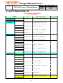
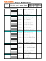
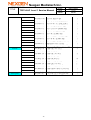
Nexgen Mediatech Inc.
T32134-AC Level 1 Service Manual
TITLE
DATE
VER
PAGE
08/15/2005
V1.0
1/36
Approved by:
Arthur Pan
Title:
Level 1 Service Manual
Prepared by:
Simon Wang
Doc. No.
Preparation Date
Model
Version
Page
GSM-FUNAI-32”-01
2005/08/15
T32134-AC
V1.0
1 of 36
Version
Date of new version
V1.0
Page
Version
Date
Page
Version
Date
Contents (Revision)
2005/08/15
1
2
3
4
5
New release
6
7
8
9
10 11 12 13 14 15 16 17 18 19 20
A1.0 A1.0 A1.0 A1.0 A1.0 A1.0 A1.0 A1.0 A1.0 A1.0 A1.0 A1.0 A1.0 A1.0 A1.0 A1.0 A1.0 A1.0 A1.0 A1.0
8/15 8/15 8/15 8/15 8/15 8/15 8/15 8/15 8/15 8/15 8/15 8/15 8/15 8/15 8/15 8/15 8/15 8/15 8/15 8/15
21 22 23 24 25 26 27 28 29 30 31 32 33 34 35 36
A1.0 A1.0 A1.0 A1.0 A1.0 A1.0 A1.0 A1.0 A1.0 A1.0 A1.0 A1.0 A1.0 A1.0 A1.0 A1.0
8/15 8/15 8/15 8/15 8/15 8/15 8/15 8/15 8/15 8/15 8/15 8/15 8/15 8/15 8/15 8/15
The information contained herein is the exclusive intellectual property or confidential document of
Nexgen, and shall not be distributed, reproduced, or disclosed in whole or in part without prior written
permission of Nexgen. Nexgen shall not be liable for any information and unauthorized misuse, abuse,
modification of this document.
1
Nexgen Mediatech Inc.
TITLE
T32134-AC Level 1 Service Manual
DATE
VER
PAGE
08/15/2005
V1.0
2/36
T32134-AC LCD TV
Service
Manual
Model No: T32134-AC
Brand: Funai
2
Nexgen Mediatech Inc.
TITLE
T32134-AC Level 1 Service Manual
DATE
VER
PAGE
08/15/2005
V1.0
3/36
Table of content
1. Attention During Servicing……………………….4
2. Purpose………………………………………………5
3. Definition Of Level 1 Service……………………..5
4. Block Diagram………………………………………6
5. Disassembly/Assembly Procedures…………… 7
6. Trouble Shooting Analysis……………………...20
7. Update BIOS………………………………………..27
8. Explosion Diagram………………………………..33
9. Level 1 Spare Parts List………………………….34
3
Nexgen Mediatech Inc.
TITLE
T32134-AC Level 1 Service Manual
DATE
VER
PAGE
08/15/2005
V1.0
4/36
1. Attention During Servicing
1-1. This TV should be operated from the type of power indicated on the using
label. If you are not sure of the type of power available, consult your
dealer or local power company..
1-2. The TV shall be placed at low humidity and low dust.
1-3. Place the TV on firm flat surface carefully. The surface of the TV is plastic
material and thin glass, drop or sharp impact will cause damage to the TV.
1-4. Do not use alcohol or ammonia-based liquid to clean the TV. If necessary,
clean with a slightly damp cloth. Disconnect the TV from the power supply
before cleaning.
1-5. Remove the power supply immediately in case of abnormality occurred in
the TV, especially strange noise of smell
1-6. Turn on power for testing only after completing the assembly of the TV
include casing and tighten the screw while servicing the TV to prevent
hazard.
4
Nexgen Mediatech Inc.
TITLE
T32134-AC Level 1 Service Manual
DATE
VER
PAGE
08/15/2005
V1.0
5/36
2. Purpose
The purpose of this service manual is for the reference of Authorized Service
Provider (ASP) while proceeding level 1 service for the product mentioned in
this manual.
3. Definition Of Level 1 Service
The definition of “level 1 service” is defined by Service Provider (SP hereafter)
based on service efficiency and effectiveness considerations. Normally level 1
means PCBA、Mechanical Parts、Internal Cable、Accessory Component、
Packing Material for LCD TV, The concrete composition of level 1 spare parts
will be mentioned in item 9, to show the level 1 list of materials.
5
Nexgen Mediatech Inc.
TITLE
T32134-AC Level 1 Service Manual
DATE
VER
PAGE
08/15/2005
V1.0
6/36
4. Block Diagram
LCD Panel
Inverter
MCU
LCD Panel Interface
Audio
Processor
&
LCD
Amplifier
SDRAM
Controller
DC/DC Converter
TV Module
TV
Interface
A/D Converter
Video Decoder
Graphic Interface
Audio & Power Interface
Speaker-R
OSD Keypad & Indicate LED
Power
&Speaker Connector
Speaker-L
6
Adapter
To CATV
Nexgen Mediatech Inc.
TITLE
T32134-AC Level 1 Service Manual
DATE
VER
PAGE
08/15/2005
V1.0
7/36
5. Disassembly/Assembly Procedures
MODEL: T32134-AC
Tools.
Disassembly steps:
1.Take off AV, Cable, and PC Cover.
AV
Cover
AV, Cable, and PC Cover.
PC
Cover
AV
Cover
PC
Cover
Cable
Cover
Cable
Cover
2. Recline TV set, release 4 screws and
remove Stand down toward as arrow.
Stand Kit.
7
Nexgen Mediatech Inc.
TITLE
T32134-AC Level 1 Service Manual
3. Release 12 screws.
3-1. Release 5 screws.
3-2. Release 3 screws and take off Back
Cover.
Back Cover.
8
DATE
VER
PAGE
08/15/2005
V1.0
8/36
Nexgen Mediatech Inc.
TITLE
T32134-AC Level 1 Service Manual
4. Release 4 screws and take off Wall
Mount Bracket.
DATE
VER
PAGE
Wall Mount Bracket.
5. Release 4 screws of Power Supply.
Power Supply.
5-1. Take off 2 wires and Power Supply.
9
08/15/2005
V1.0
9/36
Nexgen Mediatech Inc.
TITLE
T32134-AC Level 1 Service Manual
DATE
VER
PAGE
6.Release 10 screws of Main Cover Bracket.
7. Release 6 screws of PC Panel Bracket
and take off.
PC Panel Bracket
8. Release 5 screws and take off AV
Panel Bracket.
AV Panel Bracket.
10
08/15/2005
V1.0
10/36
Nexgen Mediatech Inc.
TITLE
T32134-AC Level 1 Service Manual
9. Take off Main Cover Bracket by arrow
direction.
DATE
VER
PAGE
Main Cover Bracket.
10. Take off Video Board.
10-1. Release 6 screws of Video Board.
11
08/15/2005
V1.0
11/36
Nexgen Mediatech Inc.
TITLE
T32134-AC Level 1 Service Manual
10-2. Take off 3 wires of Video Board.
Video Board.
11. Take off Main Board.
11-1. Release 8 screws of Main Board.
12
DATE
VER
PAGE
08/15/2005
V1.0
12/36
Nexgen Mediatech Inc.
TITLE
T32134-AC Level 1 Service Manual
11-2.Take off 10 wires of Main Board.
DATE
VER
PAGE
Main Board.
12.Take off Function Key Kit.
12-1.Release 2 screws and the wire.
Function Key Kit.
13
08/15/2005
V1.0
13/36
Nexgen Mediatech Inc.
TITLE
T32134-AC Level 1 Service Manual
DATE
VER
PAGE
13.Take off IR Board.
13-1. Take off IR Board.
IR Board.
14. Release left and right each 8 screws of
Speaker Rear Cover.
Speaker Rear Cover.
14
08/15/2005
V1.0
14/36
Nexgen Mediatech Inc.
TITLE
T32134-AC Level 1 Service Manual
15. Release left and right each 4 screws of
Speakers.
16. Take off Inverter Connector.
16-1. Take off Connector Wire of Inverter by
arrow direction.
15
Speakers.
DATE
VER
PAGE
08/15/2005
V1.0
15/36
Nexgen Mediatech Inc.
TITLE
T32134-AC Level 1 Service Manual
DATE
VER
PAGE
08/15/2005
V1.0
16/36
17.Take off Panel Connector.
Take off the black sticky tape.
17-1.Release screw of Ground Wire.
17-2.Press and take off Panel Connector by
red arrow direction
18. Take off Frame Support + Front Base.
16
Nexgen Mediatech Inc.
TITLE
T32134-AC Level 1 Service Manual
DATE
VER
PAGE
08/15/2005
V1.0
17/36
18-1. Release 5 screws and take off Stand
Frame Support + Front Base.
Stand Frame Support + Front Base.
19. Release 4 screws of Front Base and
take off Stand Frame Support.
Stand Frame Support.
Front Base
17
Nexgen Mediatech Inc.
TITLE
T32134-AC Level 1 Service Manual
DATE
VER
PAGE
08/15/2005
V1.0
18/36
20. Release left and right each 6 screws of
Speaker Panel +Speaker Support .
Speaker Panel +Speaker Support .
21. Release 4 screws.
Speaker Panel and Speaker Support .
Speaker
Panel
Speaker
Panel
22.Release 14 screws of Panel Bracket and
take Front Bezel apart.
18
Front Bezel
Speaker
Panel
Nexgen Mediatech Inc.
TITLE
T32134-AC Level 1 Service Manual
23. Release 4 screws of Panel and take
Panel Bracket apart.
DATE
VER
PAGE
Panel Bracket.
24. Back view of Panel.
Don’t
disassembly
inverter
Please pay attention to two
places, please don't touch
and striking.
19
08/15/2005
V1.0
19/36
Nexgen Mediatech Inc.
TITLE
T32134-AC Level 1 Service Manual
DATE
VER
PAGE
08/15/2005
V1.0
20/36
6. Trouble Shooting Analysis
Defect Mode
Failure Analysis
Light On
Test
Missing Line
Abnormal
Display
Repair
Check PCB
M/B Change
Check Panel
Panel Change
Check Panel
Panel Change
Check PCB
M/B Change
Check Panel
Panel Change
Check PCB
M/B Change
Check Panel
Panel Change
Testing
Bright Dot
Dark Dot
Backlight
Light Leakage
Mura
Image Sticking
Brightness Spot
Particle
Dot Defect
No Display
Noise
Next Step
A
NG
TEST
Completed
20
Nexgen Mediatech Inc.
T32134-AC Level 1 Service Manual
TITLE
Defect Mode
Failure Analysis
DATE
VER
PAGE
08/15/2005
V1.0
21/36
Repair
Testing
A
Flicker
Check PCB
M/B Change
Image Is
Too Dark
Check Panel
Panel Change
Gray
Value
Display
Check PCB
M/B Change
Check Panel
Panel Change
Check PCB
M/B Change
Check Panel
Panel Cable Change
Check PCB
M/B Change
Check Panel
Panel Change
Check PCB
M/B Change
Check D-sub Cable
D-sub Cable Change
Check PCB
M/B Change
R. G. B
Display
Abnormal
Display
Shut
Down
VGA No
Image
Power On
Display
Abnormal
Next Step
NG
TEST
Completed
21
Nexgen Mediatech Inc.
TITLE
T32134-AC Level 1 Service Manual
Defect Mode
ON/OFF
Abnormal
LED
Display
Abnormal
Failure Analysis
No Power
LED Off
DATE
VER
PAGE
08/15/2005
V1.0
22/36
Repair
Check PCB
M/B Change
Check Keypad/B
Keypad/B Change
Check FFC
FFC Change
Check PCB
M/B Change
Testing
Keypad/B Change
LED Dark
Check FFC
FFC Change
LED Flicker
Power Saving Mode
On VGA
Push Any Key
To Restart
Unavailable
Check PCB
M/B Change
LED Abnormal
Abnormal
Keyboard
Keypad/B Change
Check FFC
FFC Change
NG
Next Step
TEST
Completed
22
Nexgen Mediatech Inc.
TITLE
T32134-AC Level 1 Service Manual
Defect Mode
Other
Abnormal
Display
Failure Analysis
Display Flicker
(Tapping)
Cannot Use
Remote Control
DATE
VER
PAGE
08/15/2005
V1.0
23/36
Repair
Check PCB
M/B Change
Check Panel
Panel Change
Testing
Check Keypad Board
Keypad Change
Check Remote
Remote Control
Or Battery Change
Check FFC
FFC Change
TEST
Next Step
23
NG
Completed
Nexgen Mediatech Inc.
TITLE
T32134-AC Level 1 Service Manual
Defect Mode
Audio
Abnormal
Failure Analysis
DATE
VER
PAGE
08/15/2005
V1.0
24/36
Repair
Sound Adjust
Abnormal
Check PCB
M/B Change
No Sound
Check Speaker
Speaker Change
Check FFC
FFC Change
Check PCB
M/B Change
Single Sound
Testing
Keypad/B Change
Hear Phone
Defect
Check Hear
Phone Jack
M/B Change
Check FFC
FFC Change
Check PCB
M/B Change
TEST
Completed
24
Nexgen Mediatech Inc.
TITLE
T32134-AC Level 1 Service Manual
Defect Mode
Video
Abnormal
( AV , SV ,
CV , TV )
Failure Analysis
AV , SV ,CV
No Image
DATE
VER
PAGE
08/15/2005
V1.0
25/36
Repair
Check PCB
M/B Change
Check Cable
Cable Change
Check PCB
M/B Change
Check RF Cable
RF Cable Change
Check TV Module
TV Module Change
Check PCB
M/B Change
Check TV Module
TV Module Change
TV No Image
TV No Sound
Testing
TV No Close
Caption
Or V-Chip
(NTSC)
TV No
Teletext
( PAL ,
SECAM )
TEST
Completed
25
Nexgen Mediatech Inc.
TITLE
T32134-AC Level 1 Service Manual
Defect Mode
Abnormal
BIOS
Upgrade
Failure Analysis
Can’t Upgrade
BIOS
DATE
VER
PAGE
08/15/2005
V1.0
26/36
Repair
Check PCB
M/B Change
Check Firmware IC
Firmware IC
Testing
TEST
Completed
26
Nexgen Mediatech Inc.
TITLE
T32134-AC Level 1 Service Manual
7. Update BIOS.
①.Under TV Mode, press CHT
& VOLW Buttons at same time,
then press MENU Button.
②.Showing F/W Version in the
Factory Mode.
(The right side Factory Mode picture
is an example.)
③.Pressing CHT move to ISP.
27
DATE
VER
PAGE
08/15/2005
V1.0
27/36
Nexgen Mediatech Inc.
TITLE
T32134-AC Level 1 Service Manual
④.Pressing VOL W or XButton, It is
showing RUN and locks the keypads.
⑤. RS-232 port location.
⑤-1. Connecting RS-232 Cable
to TV set.
28
DATE
VER
PAGE
08/15/2005
V1.0
28/36
Nexgen Mediatech Inc.
TITLE
T32134-AC Level 1 Service Manual
⑤-2. Connecting to the computer’s
RS-232 port.
⑥. To execute CPU IspWriter.exe
program on your PC, as the right
screen appeared:
⑦.Clicking【Select Chip】or【 ▼ 】
to select“W79E632”.
29
DATE
VER
PAGE
08/15/2005
V1.0
29/36
Nexgen Mediatech Inc.
TITLE
T32134-AC Level 1 Service Manual
⑧. Clicking【Select File0】or【 ▼ 】
to select “*.H00”.
⑨.Selecting “Inte Hex", press “OK”
next.
⑩.Pressing【Select File1】or【 ▼ 】
to select “*.H01”.
30
DATE
VER
PAGE
08/15/2005
V1.0
30/36
Nexgen Mediatech Inc.
TITLE
T32134-AC Level 1 Service Manual
⑪. Confirming the connection RS-232
again, press【ConNect】next.
⑫. Showing【Connected】and
【Program All】.
⑬. Pressing【Program All】,then
start to update F/W.
31
DATE
VER
PAGE
08/15/2005
V1.0
31/36
Nexgen Mediatech Inc.
TITLE
T32134-AC Level 1 Service Manual
⑭.Showing【Program: OK!】after
update operation finished ,press
“YES” next.
⑮.After completed update F/W
operation, pull out AC power cord,
then insert again. Turn on the power
and into Factory Mode
“DATA RECALL”, press VolW or X,
resume default.
Below set, there is
no function.
⑯. Pull out AC power cord while After
update failing,press CHT and VOLX
stay ,then insert AC power cord,free
two buttons and wait for 5 seconds,
begin to update F/W.
(Jump to 27 page 5 item).
32
DATE
VER
PAGE
08/15/2005
V1.0
32/36
Nexgen Mediatech Inc.
TITLE
T32134-AC Level 1 Service Manual
8. Explosion Diagram
33
DATE
VER
PAGE
08/15/2005
V1.0
33/36
Nexgen Mediatech Inc.
T32134-AC Level 1 Service Manual
TITLE
DATE
VER
PAGE
08/15/2005
V1.0
34/36
9. Level 1 Spare Parts List
T32134-AC LCD (3RD ASSY)
817-321340-003
Material
P/N
PCBA
Accessory
Internal cable
SKD Bezel Kit
PCBA
STD Usage
510-271012-051
PCBA T27004 VIDEO BOARD V0.34
1
510-321001-011
PCBA T32134 MAIN BOARD V0.3
1
151-051503-002
BATTERY ALKALINE AAA 1.5V
2
170-101803-101
P-CORD 250V 5A 3P BLK 1.8M UK
1
171-081802-101
CAB AV 3RCA Y/R/W 1.8M
1
290-270020-021
T27004 REMOTE CONTROLLER-PAL
1
480-320004-011
T32134 USER'S MANUAL STD
1
481-320010-011
T32134-AC QUICK GUIDE STD
1
482-000010-011
WARRANTY CARD-FUNAI
1
174-001601-101
WIRE FC-16P P2.54 L=140MM
1
174-270205-101
WIRE T27124 TV 2IF 2P L=250
1
174-273007-101
WIRE T27124 VIDEO 30P L=330
1
174-320202-101
WIRE T32114 SPK-L 2P L=620
1
174-320204-101
WIRE T32114 SPK-R 2P L=620
1
174-320301-101
WIRE T32114 AC POWER 3P L=410
1
174-320603-101
WIRE T32114 IR 6P L=600
1
174-320604-101
WIRE T32114 DC POWER 6P L=600
1
174-321002-101
WIRE T32114 KEYPAD 10P L=130
1
174-322201-101
WIRE T32114 INV 10-12P L=270
1
174-323002-101
WIRE T32114 PANEL 30P L=160
1
531-321340-003
T32134-AC SKD BEZEL KIT-FUNAI
1
510-270005-011
PCBA T27124 IR BOARD V1.0
1
200-270048-0101 T27001 LIGHT GUIDE-FINESSE
1
200-270077-0101 T27124 POWER BUTTON
1
200-320009-0101 T32134 FRONT BEZEL
1
200-320024-0101 T32134 FRONT BASE
1
220-270015-011
T27124 RUBBER FOOT
4
250-320013-011
T32134 STAND FRAME SUPPORT
2
462-000010-011
LOGO FUNAI
1
479-000003-011
HD READY LABEL
1
601-040008-140
SCREW BH M4-0.7*8 C2
12
601-430008-040
SCREW BH D3*8 C2
2
601-740012-140
SCREW BH D4*12 C2
5
T32134 FUNCTION KEY KIT-STD
1
PCBA NLC27C1 KEY BOARD
1
Function Key Kit 533-320001-001
PCBA
English Description
510-272003-021
34
Nexgen Mediatech Inc.
TITLE
T32134-AC Level 1 Service Manual
174-321002-101
Stand Kit
SKD Speaker Kit
Packing material
Mechanical parts
DATE
VER
PAGE
08/15/2005
V1.0
35/36
WIRE T32114 KEYPAD 10P L=130
1
200-320010-0101 T32134 FUNCTION KEY
1
200-320011-0101 T32134 FUNCTION PANEL
1
601-430008-040
SCREW BH D3*8 C2
3
650-040109-000
WASHER FIBER T=1.0
1
527-320006-001
T32134-XC STAND KIT-STD
1
200-320017-0101 T32134 STAND BASE COVER_C
1
200-320019-0101 T32124 STAND SIDE COVER
2
220-270015-011
T27124 RUBBER FOOT
8
250-270056-021
T27124 HINGE MODULE A
1
250-320010-011
T32134 STAND BASE PLATE
1
250-320014-011
T32134 STAND FRAME
2
250-320020-011
T32134 STAND FRAME PLATE
1
601-740008-040
SCREW BH D4*8 C2
12
603-040012-140
SCREW IH M4-0.7*12 C2
6
609-040010-010
SCREW PH+SW+W(10) M4-0.7*10 C2
4
609-040015-140
SCREW PH+W+SW M4-0.7*15 C2
6
534-320005-001
T32134-AX SKD SPEAKER KIT
1
154-100808-101
SPK 10W 8R 266*61*50 L=180
2
200-320012-0102 T32134-AX SPEAKER PANEL_R
1
200-320013-0101 T32134 SIDE PANEL
2
200-320015-0102 T32134-AX SPEAKER PANEL_L
1
200-320016-0101 T32134-AX SPEAKER REAR COVER
2
250-320009-031
T32134 SPEAKER SUPPORT
4
600-040012-010
SCREW PH M4-0.7*12 C2
8
601-740012-140
SCREW BH D4*12 C2
4
601-740016-040
SCREW BH D4*16-MULTISTROKES
4
240-420001-011
CARTON LOCK
2
401-320003-011
T32134_A BOTTOM CARTON
1
401-320022-021
T32134 MAIN CARTON-FUNAI UK
1
403-320004-011
T32134_A EPE CUSHING TOP RIGHT
1
403-320005-011
T32134_A EPE CUSHING TOP LEFT
1
403-320009-011
T32134_A EPE CUSHING BOTTOM
1
404-000009-011
RECLOSEABLE BAG
1
404-320004-011
T32134-AX MEALIE BAG
1
185-019201-101
AC/DC P-SUPPLY 192W 100~240V
1
200-320008-0101 T32134 PC COVER
1
200-320020-0101 T32134 AV COVER
1
200-320021-0101 T32134 BACK COVER
1
35
Nexgen Mediatech Inc.
TITLE
Screws
Other parts
T32134-AC Level 1 Service Manual
DATE
VER
PAGE
08/15/2005
V1.0
36/36
200-320023-0101 T32134 CABEL COVER
1
210-270027-011
T27124 PC I/O NAME PLATE PAL
1
210-270029-011
T27124 AV I/O NAME PLATE PAL
1
230-320007-011
T32001 PANEL MYLAR SHEET
1
250-270053-011
T27124 MAIN COVER BRACKET
1
250-270073-011
T27124 AV PANEL BRACKET
1
250-320006-011
T32134 PANEL BRACKET
1
250-320015-011
T32134 WALL MOUNT BRACKET
2
250-320018-011
T32134 PC PANEL BRACKET
1
460-320015-011
T32134 SAFETY LABEL-FUNAI UK
2
461-000004-011
SPEAKER CAUTION LABEL
1
485-320002-011
T32134-A SPEAKER CAUTION SHEET
1
600-040012-010
SCREW PH M4-0.7*12 C2
4
601-030008-140
SCREW BH M3-20*8
5
601-040008-140
SCREW BH M4-0.7*8 C2
13
601-430008-040
SCREW BH D3*8 C2
9
601-740012-140
SCREW BH D4*12 C2
40
602-030006-110
SCREW WH7 M3-0.5*6 C2
26
604-030008-140
SCREW FH M3-0.5*8 C2
2
605-204007-011
SCREW HH UNC4#-40*7 H5
6
609-040006-030
SCREW PH+SW+TW(8.4) M4-0.5*6C2
1
609-040015-140
SCREW PH+W+SW M4-0.7*15 C2
4
180-320001-101
32" LCD PANEL MODULE 1366*768
1
36