1
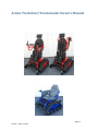
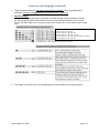
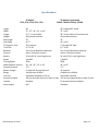
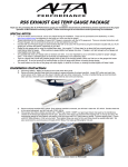
This page intentionally blank When printing start by printing pg. 1-18 THIS PAGE DOES NOT PRINT Demo Form Date ____________________________ Location ___________________________ Safety instructions: Only one person on Trackchair at a time. Know the limits of the Trackchair. The Trackchair will climb an incline high enough to tip over. Failure to know limits can cause personal injury or equipment damage. Always have an able-bodied person close enough to help out in need. Do not ride on Trackchair when loading on trailer or vehicle. Page | 1 Revised ~ August 15, 2015 This page intentionally blank Page | 2 Revised ~ August 15, 2015 Action Trackchair/Trackstander Owner’s Manual Page | 3 Revised ~ August 15, 2015 Action Manufacturing 1105 Lake Road Marshall, MN 56258 507-532-5940 www.actiontrackchair.com Table of Contents Forms Triplicate Registration Form……………………………………………………………………………………………………….. Demo Form………………………………………………………………………………………………………………………………...1 Table of Contents……………………………………………………………………………………………………................................. 4 Introduction .................................................................................................................................................. 5 Safety ............................................................................................................................................................ 6 Operating the Action Trackchair ................................................................................................................... 7 Comfort Adjustments.................................................................................................................................... 8 Batteries and Charging……………..……………………………………………………………………….…………………….........9 & 10 Repair and Maintenance............................................................................................................................. 11 Warranties .................................................................................................................................................. 12 Specifications .............................................................................................................................................. 13 Table 1: Hand Control Fault & Warning Indicators .............................................................................14 & 15 Strapping Methods with Trackchair Carrier ................................................................................................ 16 Rocker Switch Override Instructions…………………………………………………………………………..............................17 Law, Regulation and Policy for Wheelchair/Mobility Device Use in “Federally Designated Wilderness………………….18 Page | 4 Revised ~ August 15, 2015 Introduction Welcome to Action Trackchair. We at Action Trackchair want to make your experience the best it can be. Enclosed in this owner’s manual you’ll find information to use and maintain your Action Trackchair. With any questions please contact us at: Action Manufacturing 1105 Lake Road PO Box 620 Marshall, MN 56258 507-532-5940 [email protected] [email protected] Page | 5 Revised ~ August 15, 2015 Safety Guidelines Only one person should be on the Trackchair at any time. Seat belt is recommended. Do not navigate Trackchair/Trackstander on more than a 20 degree slope Trackchair will climb inclines enough to tip over in any direction. When climbing over small logs or curbs approach incline at an angle, not directly at 90° Make sure controls are in the off position before sitting in Trackchair and before getting out of seat. Always have a backup plan, “What if…?” Do not ride the Trackchair during loading or unloading from vehicle or carrier. Do not attempt to climb stairways. Action Manufacturing Inc. does not recommend driving the Trackstander in the upright position other than flat and stable terrain Failure to know the limits can cause personal injury or equipment damage Page | 6 Revised ~ August 15, 2015 Operating Your Action Trackchair When you are ready to drive the Trackchair, make sure controls are in the off position before sitting in Trackchair. If your Trackchair has a locking control, it can be unlocked in this way. Turn control on, hold joystick forward until you hear a beep or three seconds, then joystick back until you hear a beep or three seconds. It is now unlocked and ready for operation. When locking the control, it is done in this way. After the control has been turned off, hold the on/off button until the control has cycled both on and then off. Control is now set in the locked mode. The Action Trackchair control has five speeds, one-five and can be changed with the up and down arrows. Battery indicator is on the main screen on controls. Battery charge will last up to six hours, depending on battery condition and type of use the Trackchair is subject to. Action Trackchair has a built-in battery charger that plugs into 110 voltage. Optional lighting is available and is controlled on the joystick control panel. Tilting of the chair is possible by pushing the “M” button on controls, and then moving joy stick forward or backward to tilt chair. Cancel by pushing “M” again or moving joystick to the left. A “tilt on the fly” switch is an option for tilting the Trackchair independent of joystick. If for some reason it is necessary to pull the Trackchair. Disengage the brakes on the motors with the levers on back of motors. Push levers to the outsides on both motors. Do not pull Trackchair more than 5 MPH Page | 7 Revised ~ August 15, 2015 Comfort Adjustments There are few adjustments that are necessary. The foot rest can be moved up or down to fit the rider’s needs. The chair itself can be leveled to the desired comfort of the rider. The armrest can flip down or back for easier transferring into the chair. Electronic controls can be adjusted at a servicing distributor/dealer as far as speed, acceleration, deceleration, braking, etc. Revised ~ August 15, 2015 Page | 8 Batteries and Charging Battery charge will last up to six hours, depending on battery condition and type of use the Trackchair is subject to (terrain and weight of rider). The Trackchair has a built-in battery charger that plugs into 110 voltage. Pro Mariner Charger: ProSport includes 7 LEDs for operation status and up to 3 battery bank trouble LEDs depending on the model. 1. The blue AC power LED Illuminates when AC power is applied 2. The battery type LED Will illuminate red for standard Flooded (lead-acid)/AGM and green for GEL. Note: The ProSport 20 Dual bank model includes an amber battery type LED for AGM HP (High Performance) battery type. Please read the battery manufacturer literature carefully and select the correct charge profile. Failure to do so may cause early battery failure. 3. The system check OK LED After applying AC power the ProSport will self-test and analyze all battery connections and batteries. If all checks are OK the green LED will illuminate. This can take up to 2 minutes. 4. The charge mode LEDs Charging: Red LED will flash during the self-test and battery test mode (approximately 1-2 minutes) and will be solid red during charging. Conditioning: Amber LED illuminates during conditioning mode. Ready / maintain: Green LED illuminates when batteries are fully charged and being automatically maintained until you are ready to use your boat. Storage recondition: Green LED fades in and out when performing a once a month storage recondition mode. 5. Battery bank trouble status LEDs Red LEDs will illuminate indicating a wiring problem or fault at one of the batteries connected to the ProSport charger. See page 21 of charger manual for further details. Operation after Applying AC Power to a ProSport Charger Connected to Discharged Batteries During the startup test the battery type LED will be illuminated and the red charge mode LED will flash indicating that the unit is in a self-test mode. When complete and if there are no faults, the charger's system check OK indicator will illuminate green and the ProSport's solid red charging LED will be ON indicating the charge process is initiated. Note: If there is a fault the appropriate bank LED will illuminate and the charge process may not start, depending on the location of the fault. See page 21 for further troubleshooting details. If There are no Battery Faults, the Green System Check OK LED will Illuminate and the Following Sequences will proceed: The red battery type LED (factory set for standard Flooded (lead-acid)/AGM batteries) will illuminate. The red charge mode LED will illuminate indicating the charger has started its multi-stage charging process. When the charge process is approximately 80% complete the red charge mode indicator will turn off and the amber conditioning LED will turn on indicating the conditioning mode. When the multi-stage charge process is completed you will observe the following: Battery type red LED goes OFF. The red charging LED and the amber conditioning LED will be off and the green ready/maintain LED will illuminate indicating your batteries are fully charged. The only LEDs on after the multi-stage charge process is completed are the green system OK LED, blue AC power LED and the green ready/maintain LED. Multi-Stage Charging Overview ProSport Charging: During this mode the “Charging” indicator will be red. ProSport will use all of its available charging amps (as controlled by temperature) until the battery voltage is raised to 14.6VDC (Flooded lead-acid factory setting). ProSport Conditioning: During this mode the “Conditioning” status indicator will be amber. Batteries will hold at 14.6 VDC (factory set for Flooded lead-acid batteries) to complete charging while conditioning each battery connected. Upon completion the ProSport will go into its maintain mode. ProSport Ready / Maintain: During this mode the “Ready/Maintain” status indicator will be green and remain on with the blue “power” LED indicating that your batteries are fully charged while being maintained at a precision 13.4 volts (factory set for Flooded lead-acid batteries) and are ready to go when you are. ProSport Storage Recondition Mode: During this mode the ProSport “Recondition Mode” green indicator will illuminate with a slow fade in and out pulse indicating that while your batteries/boat are in storage the ProSport will automatically recondition all batteries for up to 3 hours once a month extending battery life and maximizing on the water battery power performance. Revised August 15, 2015 Page | 9 Batteries and Charging (Continued) To get maximum daily use, the battery must be fully charged. This is accomplished by having the Trackchair plugged in until the “READY LIGHT” comes on. Dual Pro Charger: When your battery charging system is activated, each bank provides charging information utilizing five red Light Emitting Diode (LED) indicators and one green Light Emitting Diode (LED) indicator. The five red LEDs enable you to track the progress of the charge cycle on each battery as the voltage rises. 2 to 12.78 volts = 10% 12.79 to 13.25 volts = 10%, 30% 13.26 to 13.49 volts = 10%, 30%, 50% 13.50 to 14.04 volts = 10%, 30%, 50%, 70% 14.05 to 14.52 volts = 10%, 30%, 50%, 70%, 90% Green Flashing {Finishing Stage} 14.52 to 15.49 volts The charger can be left on for an extended period of time without harming the battery. Revised August 15, 2015 Page | 10 Repairs and Maintenance All bearings are sealed and need no additional greasing. Track can be adjusted by loosening both bolts on the front idler wheels, inside and outside. Track tensioners can be tightened with a 9/16 wrench by holding the lock nut and turning track tensioner bolts clockwise an even amount. It is not necessary to over tighten track. Re-tighten front idler wheels, inside and outside to 130 in./lbs. Cleaning your Trackchair/Trackstander The Action Trackchair/Trackstander can be washed with a garden hose, do not use high pressure wash to clean the chair. Always cover the joystick with a plastic bag to protect it from getting moisture inside. THE JOYSTICK IS NOT WATERPROOF and should be covered when washing, or stored outside or when transporting behind the vehicle open. Do not spray water directly onto the motor controller under the seat. Revised August 15, 2015 Page | 11 Warranties 1 YEAR: The following components are covered against manufacture defects in materials and workmanship for the period of one year. o Batteries o Control box and joy stick o Motors o All sprockets and idler wheels o Seats o Tilt Actuator o All other parts 1 year Parts and Labor. 2 YEARS: The following components are covered against manufacture defects in materials and workmanship for the period of two years. o ProSport battery charger (Trackchair) 1st Year- Parts and Labor 2nd Year- Parts Only. 3 YEARS: The following components are covered against manufacture defects in materials and workmanship for the period of three years. o Dual Pro battery charger (Trackstander) 1st Year- Parts and Labor 2nd and 3rd Years- Parts Only. Tracks 1st Year- Parts and Labor 2nd and 3rd Years- Parts Only. Frame welding (Trackchair/Trackstander) Warranty period starts @ delivery date to customer. Revised August 15, 2015 Page | 12 Specifications ST Models ST16, ST18, ST20, ST22, ST24 Height Width Length Weight Seat height Seat Depth Tilt angle for chair Track Size Batteries Controls Motors Speed Turning Radius Width between armrest Ground Clearance Battery Charger Range Foot rest Accessory holders Lap belt Knee support Revised August 15, 2015 TR Models Trackstander TR1816, TR1820, TR2016, TR2020 42” 37”, 37”, 39”, 41”, or 43” 52 ½ “ w/ rear idlers 350 pounds estimate 23” 16 ½” 20° each way 6 ½” X 90” Two 12 volt Wheelchair Batteries Action Trackchair controls 24 volt DC 24:1 ratio high thrust 3-4 MPH ZERO 16”, 18”, 20”, 22” or 24” 3 ½” 12 amp Std. 20 amp Optional Variable up to 6 Miles Adjustable Standard or Flip up Two on each side and two on back of chair Standard N/A 43” lowered 64” raised 37” or 39” 59” w/ rear idlers to front wheel kit 470 pounds estimate 25” 16” or 20” 5° forward/ 20° back 6 ½” X 90” Two 12 volt Wheelchair Batteries Action Trackchair controls 24 volt DC 24:1 ratio high thrust 3-4 MPH ZERO 18” or 20” 3 ½” 20 amp Std. Variable up to 6 Miles Adjustable Standard Two on each side and two on back of chair Three point harness standard Standard Page | 13 HANDCONTROL LCD DISPLAY FAULT/WARNING Power Section Fault, or Current Sensor Fault, or EEPROM Fault, or Main Relay Fault, or Precharge Fault, or HW Failsafe Fault. Handcontrol Fault, or Joystick Fault: Joystick out of center, Joystick stuck OOC, Joystick Out-of-Range Communications Fault Brake Fault. Seatback Actuator Driver Fault Seat Actuator Driver Fault. Leg Actuator Driver Fault Under voltage warning Overvoltage Warning. Revised August 15, 2015 REMEDY 1. Cycle power 2. Replace powerbase. 1. Return joystick to neutral and cycle power 2. Recalibrate joystick. 3. Check joystick cable and cable connections. 4. Repalce joystick. 5. Replace hand control. 1. Check cable and cable connections. 2. Replace cable. 1. Check wiring. 2. Replace motor. 3. Replace powerbase. 1. Select drive or a different actuator; fault may clear. 2. Check wiring. 3. Check that the seatback is not jammed. 4. Check actuator; replace if faulty. 5. Replace powerbase. 1. Select drive or a different actuator; fault may clear. 2. Check wiring. 3.Check that the seat is not jammed. 4. Check actuator; replace if faulty. 5. Replace powerbase. 1. Select drive or a different actuator; fault may clear 2. Check wiring. 3. Check that the leg rest is not jammed 4. Check actuator; replace if faulty. 5. Replace powerbase. 1. Recharge battery. 2. Replace old battery. 3. If this is happening frequently, replace charger. 4. Check charger port on hand control; replace if damaged. 1. Wait for voltage to come down 2. Replace old battery. 3. Check charger; replace if faulty Page | 14 Controller Over/Under temperature warning. Revised ~ August 15, 2015 1. If too hot, wait for controller to cool. 2. If too cold, drive chair in limited current mode until controller warms up. Drive Thermal Warning 1. Wait for motor to cool. Open Motor Fault 1. Check wiring. 2. Replace motor. 3. Replace powerbase. Left Indicator Fault 1. Press Left Indicator button. 2. Replace Bulb. 3. If fault continues, check wiring. Right Indicator Fault. 1. Press Right Indicator button 2. Replace bulb. 3. If fault continues, check wiring. Hazard Lights Fault. 1. Press Right or Left Indicator button. 2. Replace bulb. 3. If fault continues, check wiring. Running Lights Fault 1. Press Running Lights button. 2. Replace bulb. 3. If fault continues, check wiring. Speed Limit Warning. 1. Return seat to normal or upright position. 2. If fault continues, check all limit switches and wiring. Low battery 1. Recharge battery. Locked Mode. * 1. Unlock the system. Chair under attendant control. * 1. Turn off attendant control (1742) Battery charging; Inhibit. * 1. Unplug charger when charging is complete. * These icons indicate a problem only if they appear when they shouldn't. 15 Strapping Methods Proper strapping options for Trackchair to carrier ***Class III receiver hitch required for carrier, Check auto manufacturers recommendation for hitch capacity*** Class III—2”-- Up to 6,000 pounds towing capacity, up to 600 pounds tongue weight Revised ~ August 15, 2015 16 Rocker switch override instructions Actuator not moving up or down? First check the fuse in the black fuse holder located at the black & red, 16 gauge wire harness which comes off the battery, fuse type is a ATC 20 amp. If you suspect the actuator has failed and you have a “Tilt on the Fly” rocker switch, (not tilt through the joystick) you can simply bypass the rocker switch as follows: Locate wire coming out of the side of the actuator, unplug from the current plug it is attached to. Plug lead from actuator into blue/yellow lead from the 14 pin connector which is located under the seat. Now turn joystick on and press the “M” button, move the joystick forward or reverse and the actuator should move up or down. If you find that the actuator does work, then the problem would be in the “Tilt on the Fly” rocker switch or wiring to it. Revised ~ August 15, 2015 17 Tilt on the fly wiring Tilt with joystick Fuse holder Revised ~ August 15, 2015 18 Law, Regulation and Policy for Wheelchair/Mobility Device Use in “Federally Designated Wilderness (ADA Title V Section 508c, as amended in 2008) (1) IN GENERAL – Congress reaffirms that nothing in the Wilderness Act prohibits wheelchair use in a wilderness area by an individual whose disability requires its use. The Wilderness Act requires no agency to provide any form of special treatment or accommodation or to construct any facilities or modify any conditions of lands within a wilderness area to facilitate such use. (2) Definition – for the purposes of paragraph (1), the term wheelchair means a device designed solely for use by a mobility impaired person for locomotion, that is suitable for use in an indoor pedestrian area.” (per American with Disabilities Act, Title V Section 508 (c) Application: “Designed solely for use by a mobility-impaired person” means that the original design and manufacture of the device was only for the purpose of mobility by a person who has a limitation on their ability to walk. “Suitable for indoor pedestrian use” means the device would be allowed to be used inside a mall, etc. A wheelchair or mobility device, even one that is a battery powered, that meets both parts of this definition is allowed anywhere foot travel is allowed including in federally designated wilderness areas. The following CFR and FSM apply in ALL areas of the National Forest System 36 Code of Federal Regulation (CFR) 212.1 “Motor Vehicle. Any vehicle which is self-propelled, other than: (1) a vehicle operated on rails; and (2) any wheelchair or mobility device, including one that is battery-powered, that is designed solely for use by a mobility-impaired person for locomotion, and that is suitable for use in an indoor pedestrian area.” Forest Service Manual 2353.05“Wheelchair or Mobility Device. A device, including one that is battery-powered, that is designed solely for use by a mobility-impaired person for locomotion, and that is suitable for use in an indoor pedestrian area. A person whose disability requires use of a wheelchair or mobility device may use a wheelchair or mobility device that meets this definition anywhere foot travel is allowed.” Application: “Designed solely for use by a mobility-impaired person” means that the original design and manufacture of the device was only for the purpose of mobility by a person who has a limitation on their ability to walk. “Suitable for indoor pedestrian use” means the device would be allowed to be used inside a mall, etc. A wheelchair or mobility device, even one that is a battery powered, that meets both parts of this definition is allowed anywhere foot travel is allowed Revised ~ August 15, 2015 19