1
TK-2180
CIRCUIT DESCRIPTION
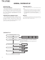
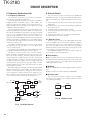
■ High-speed data (5-tone)
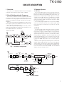
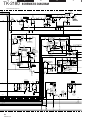
7-2. Decode
■ Low-speed data (QT, DQT)
The demodulated signal from the IF IC (IC200) is amplified
by IC600 (1/2) and passes through an audio processor (IC607)
and amplifier IC604 (1/2) and comparator IC604 (2/2) to remove a low-speed data. The CPU digitizes this signal and
decodes the signal.
The demodulated signal from the IF IC (IC200) is amplified
by IC600 (1/2) and passes through a low-pass filter (IC607) to
remove audio components. The signal is input to pin 128 of
the CPU.
The CPU digitizes this signal, performs processing such as
DC restoration, and decodes the signal.
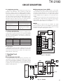
■ MSK
The MSK input signal from the IF IC is amplified by IC600
(1/ 2) and goes to pin 5 of IC607. The signal is demodulated
by MSK demodulator in IC607. The demodulated data goes
to the CPU for processing.
■ High-speed data (DTMF)
The DTMF input signal from the IF IC (IC200) is amplified
by IC600 (1/2) and goes to IC607, the DTMF decoder. The
decoded information is then processed by the CPU. During
transmission and standby, the DTMF IC is set to the power
down mode.
IC607
IC600
AMP
LPF
HPF
IC201
IC305
AMP
COMPARATOR
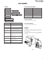
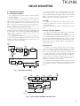
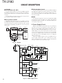
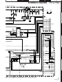
Battery +B is supplied via a 2.5A fuse from the battery
terminal connected to the TX-RX unit. Power supply (+B) is
applied to the four AVRs. IC402 supplies 5V (5M) to the control circuit. IC401 and IC403 supplies 5V to common circuits.
IC406 supplies to the TX circuit, the RX circuit and common
circuits. During transmission, 5TC becomes Low and Q406
is turned on to supply 5V (5T) to the TX circuit. During reception, 5RC becomes Low and Q405 is turned on to supply 5V
(5R) to the RX circuit.
The power supply voltage monitor IC (IC400) monitors
power supply voltage (+B). If the voltage falls (less than
5.6V), the VOUT port goes “LOW” level, the CPU INT port
also goes “HIGH” level, and the CPU stops.
10
HSDIN
128
LSDIN
LPF
DTMF
DECODE
XIN
8. Power Supply Circuit
XOUT
DTRLOAD
STD
DTRCLK
DTRDO
IC502
CPU
X600
Fig. 13
Decode
F400 +B
RF power amp
2.5A
Power SW
D405
IC402
Q408
5M
VOUT
VIN
CE
VDD
IC502
CPU
VIN
VOUT
IC400
OUT
IC405
Q407
RESET
INT
PSW
D403
Q401
Q502
IC403
Q409
VIN
VOUT
CE
5C
IC401
SAVE
VIN
VOUT
CONT
5CNS
5R
Q405
IC406
VIN
VOUT
CONT
5RC
5T
Q406
5TC
12
Fig. 14
Power supply circuit