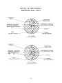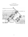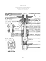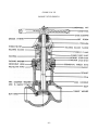
1
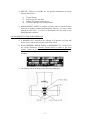
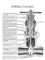
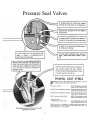
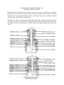
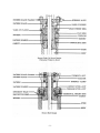
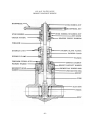
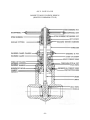
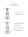
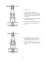
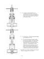
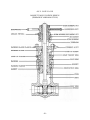
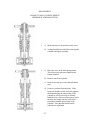
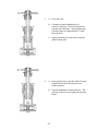
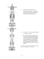
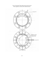
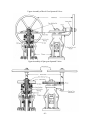
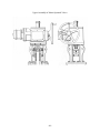
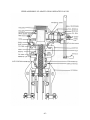
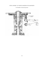
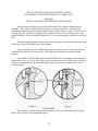
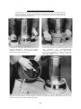
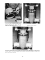
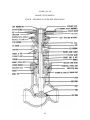
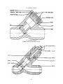
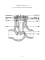
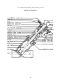
POWELL
PRESSURE SEAL
VALVES
INSTRUCTION
MANUAL
MANUAL
NUMBER
69-1
THE WM. POWELL COMPANY
2503 SPRING GROVE AVENUE
CINCINNATI, OHIO 45214
-1-
Powell Pressure Seal Valves are built to high standards of precision and accuracy and must pass rigid
inspection before leaving the factory. It is imperative that the valves be properly installed, maintained and
operated to assure satisfactory performance.
The purpose of this service manual is to instruct installation crews, maintenance foremen and operating
personnel in these fundamentals. This manual should be kept available to these presonnel at all times so that
they may become familiar with the details of these valves.
Powell Pressure Seal Valves are intended for high pressure, high temperature services of all fluids where
severe coking is not a factor. They are guaranteed to be in good condition; however, we assume no
responsibility for damage to valves due to faulty installation, improper operation or other conditions beyond
our control.
THIS BOOK IS REGISTERED IN THE
NAME OF:
___________________________________
SERIAL NO. _________________________
-2-
INDEX
Page
ADAPTO GEAR OPERATED
VALVES
Upper Assembly
ANGLE VALVES
Bonnet Take-Up Screw Design
(Bolted Yokearm Style)
Instruction for Repair of Valve
Seats
CHECK VALVES
“Y” Check
“Y” Check (Threaded Retainer
Style)
Horizontal Check
COMPONENT PARTS OF
PRESSURE SEAL JOINT
DIAGRAMATIC DESCRIPTION
Pressure Seat Joint
Bonnet Locknut Design
Bonnet Take-Up Screw Design
(Bolted Yokearm Style)
Bonnet Take-Up Screw Design
(Threaded Yokearm Style)
Bonnet Stud Design
Angle Valve
Check Valve Horizontal
Check Valve “Y”
Gate Valve Locknut Design
Gate Valve Take-Up Screw
Design (Bolted Yokearm Style)
Gate Valve Take-Up Screw Design
(Threaded Yokearm Style)
Gate Valve O.S. & Y. Bonnet
Stud Design
Globe Valve “Y”
Globe Valve Bonnet Stud Design
Globe Valve Bonnet Stud Design
Hammer Blow Handwheel
“Y” Globe Non Return
(Stop Check) Valve
DISASSEMBLY
Bonnet Locknut Design
Bonnet Take-Up Screw Design
Threaded Body to Yokearm
Design
Bonnet Stud Design
GATE VALVES
Bonnet Locknut Design
Bonnet Take-Up Screw Design
(Bolted Yokearm Style)
Bonnet Take-Up Screw Design
(Threaded Yokearm Style)
Bonnet Stud Design
Instructions for Repair of Seats
Tools for Repairing Seats
GEARING-UPPER ASSEMBLY
Bevel Gear Operated
Spur Gear Operated
Motor Operated
Adapto Gear Operated
Geared Hammer-Blow HandWheel (Air Wrench Operation)
Page
GLOBE VALVES
“Y” Take-Up Screw Design
Bonnet Stud Design
Bonnet Stud Design
(Hammer-Blow Handwheel)
“Y” Non-Return (Stop Check)
Instructions for Repair of Seats
45
60
52, 53, 54,
55, 56
INSTALLATION
Cleaning the Pipe Lines
Cleaning the Valve
Insulation
Lifting Lugs
Packing Lists
Supporting the Valve
Unloading
Welding
63
63
64
57
LAPPING
Pressure Seal Joint
Body Lapping
Bonnet Lapping
Globe, Angle, Check & NonReturn Valve
Cleaning
Compound
Special Instructions
6, 7
8
8
9
9
60
64
63
10
18
26
34
59
61
62
65
11
19
10
18
43
43
44
45
-3-
48, 49
49
47
47
48
48
47
OPERATION & MAINTENANCE
Back Seat
Lubrication
Packing Leaks
Special Tools
Replacement Parts
4
4
4
5
5
PRESSURE SEAL JOINT
Description
Detail Drawing
Component Parts
Segmental Thrust Rings
6, 7
58
57
42
VALVE IDENTIFICATION
Body Lettering
Name Plate
Ordering Repair Parts
Referring to a Valve
46
4
4
4
4
4
4
4
4
44
SECTIONAL DRAWINGS &
PART NAMES
Angle Valves
Check Valves
Gate Valves
Globe Valves
Non-Return (Stop Check) Valve
26
34
50
51
62
65
52, 53
54, 55, 56
MOTOR OPERATED VALVES
Upper Assembly
REASSEMBLY
Bonnet Locknut Design
Bonnet Take-Up Screw Design
Bolted Yokearm Style
Bonnet Take-Up Screw Design
Threaded Yokearm Style
Bonnet Stud Design
27
35
59
61
15
23
31
39
60
63, 64
10, 18, 26, 34
59, 61, 62
65
5
5
5
5
INSTALLATION
When your valves arrive you will find an envelope containing a PACKING LIST – an itemized
statement of all valves and parts included in the shipment. The Receiving Clerk should check and
account for each item on the list. Keep this PACKING LIST as a part of the permanent records of these
valves.
UNLOADING of valves should be done with care. Remember that although a valve is a rugged
piece of equipment it may still be damaged by abusive handling. Skidded valves should not be removed
from skids until immediately before installation. LIFTING LUGS incorporated on the yokearm of many
Pressure Seal Valves greatly facilitate handling.
IMPROPER INSTALLATION of a valve can have very serious consequences resulting in
possible malfunction which may necessitate extensive and costly repairs. Compliance with the following
recommendations will do much to assure satisfactory performance of the valve after installation.
1)
CLEANING of fluid passage seating surfaces of all valves should be
accomplished before installation.
2) Provisions should be made for SUPPORTING THE VALVES and adjacent
piping so that pipe line stresses will not be transmitted to the valve bodies.
3) WELDING and stress relieving should conform to the A.S.M.E. Boiler Code.
Valve stems should be opened slightly during preheat, welding and
post
heating operations.
4) CLEANING OF THE PIPE LINES in which valves are installed and all
connecting lines is essential before the unit is put in operation. Welding
beads, scale and foreign matter in the lines cause damage to the valve seats
resulting in leakage.
5) INSULATION should not be applied to the valve above the knockout holes.
OPERATION AND MAINTENANCE
1) PACKING LEAKS should be corrected promptly by tightening the packing
gland nuts. Failure to do this may result in damaged packing and inability to
stop the leak until new packing is installed.
2) Powell Pressure Seal Valves have a BACK SEAT on the stem, which seats
against a stellited guide in the bonnet when the valve is fully opened. This
seat will hold pressure if both surfaces are clean; however, this is difficult to
determine, and consequently, packing a valve under pressure is hazardous
and not recommended.
3) LUBRICATION of the stem bushing is required periodically. This is
accomplished by grease fitting on the side of the bushing housing. Lubricant
should be added until it starts to extrude around the stem threads. Mobil
Grease Type AA No. 2 or equal is recommended.
-4-
4) SPECIAL TOOLS are available for the general maintenance of Powell
Pressure Seal Valves.
a)
b)
c)
d)
Torque Wrench
Laps for pressure seal joint
Grinder for pressure seal body seat
Tools for repairing valve sealing surfaces
5) REPLACEMENT PARTS are seldom necessary when a Powell Pressure
Seal Valve is properly installed and maintained. However, it is wise to stock
packing for each valve. If a valve be disassembled for any reason a new
gasket should be installed.
VALVE IDENTIFICATION AND REFERENCE
1) A NAMEPLATE is located on the yokearm of all pressure seal Gate and
Globe Valves, and on neck of body on all Check Valves.
2) When ORDERING REPAIR PARTS or REFERRING TO A VALVE for
any reason whatsoever, reference should always be made to the serial
number located at the bottom right-hand corner of the nameplate. In
addition, size and figure number also located on the nameplate should be
included.
3) The lettering side of the body has the following information:
-5-
POWELL Cast Steel
-6-
Pressure Seal Valves
-7-
DISASSEMBLY AND REASSEMBLY OF
THE PRESSURE SEAL JOINT
Disassembly and reassembly of the Pressure Seal Joint is simple if directions are followed.
Powell Pressure Seal Valves utilize four types of design (1) Bonnet Locknut Design, (2) Bonnet
Take-Up Screw Design (Bolted Yokearm Style), (3) Bonnet Take-up Screw Design (Threaded
Yokearm Style), and (4) Bonnet Stud Design.
Although Gate Valves are illustrated with the disassembly and reassembly instructions for the
various types of Powell Pressure Seal Joint Designs on the following pages, these instructions
also apply, with minor modifications, to Globe, Angle, Non-Return (Stop-Check) and Check
Valves.
-8-
-9-
O.S. & Y. GATE VALVE
BONNET LOCKNUT DESIGN
- 10 -
DISASSEMBLY
BONNET LOCKNUT DESIGN
1.
a) Make sure there is no pressure in the valve.
b) A sling should be provided for removing the
yokearm and upper assembly.
2.
a) Place the valve in the half-open position.
This relieves any pressure trapped in the
bonnet chamber.
b) Remove eyebolt nuts and eyebolt bolt nuts.
Remove eyebolt bolts, eyebolts and eyebolt
clamp.
c) Remove the yokearm nuts.
d) Completely loosen bonnet locknut
e) Tap the bonnet until it slides into the body
and frees the segmental thrust ring.
- 11 -
3.
a) Close the valve.
b) Continue to turn the handwheel in a
clockwise direction. This will separate the
yokearm from the body. Stop separating the
yokearm when it is approximately 2” apart
from the body.
c) Apply penetrating oil to the segmental thrust
ring and gasket seating area.
d) Insert pin in the knockout hole and remove
the segmental thrust ring as illustrated on
page 42.
4.
a) Insert equally spaced spreader block of
equal height approximately 2” thick between
the body and yokearm contact surfaces.
b) Turn the handwheel counter-clockwise. The
yokearm will now lower against the spreader
blocks.
- 12 -
5.
a) Continue to turn the handwheel in a counterclockwise direction. As the back seat of the
stem seats against the bonnet, the bonnet,
gasket, and protective ring will be raised
from the body.
6.
a) Close the valve. This will permit the bonnet
to rest lightly in the body.
b) The yokearm and upper assembly should
now be removed intact.* This may be done
by turning the handwheel in a clockwise
direction until the stem bushing comes free
of the stem. A sling should be used for
lifting the upper assembly after it has been
freed. The packing gland flange, bonnet
locknut and bonnet locknut washer are
removed during this operation as they clear
the top of the stem.
* For other types of Upper Assemblies such as Bevel
Gear etc. see pages 43, 44, 45, and 46.
- 13 -
7.
a) Lift the bonnet along with the gland,
protective ring and gasket out of the body,
care being taken not to scar the gasket
seating surface of the body.
8.
a) Mark the wedge and body so that the wedge
may be re-installed in the same orientation.
b) Remove the wedge and stem. If no work is
to be done on the wedge it should be reinstalled in the body carefully so no damage
is done to the seating surfaces.
- 14 -
REASSEMBLY
BONNET LOCKNUT DESIGN
1.
a) The gasket seating surfaces of the bonnet
and body should be lapped and free of any
scars. See pages 48 and 49.
b) Seat Ring and wedge seating surfaces should
be inspected and repaired if necessary. See
pages 50 and 51 for instructions for
repairing gate valve seats, pages 52 through
56 for instructions for repairing globe and
angle type valve seats.
c) Clean the body and bonnet seating surfaces.
2.
a) Put the wedge and stem in place, making
sure the wedge has the same orientation as
when disassembled.
b) Insert the bonnet into the body.
- 15 -
3.
a) Put a new gasket in place, making sure all
surfaces are clean. (It is essential to install a
new gasket whenever the pressure seal joint
is broken.) (See page 47 for special
instructions.)
b) Protective ring is oversize and must be
machined or ground to fit valve.
c) Insert the segmental thrust ring (see sketch
on page 42).
d) Put the packing washer and gland on the
stem.
4.
a) Place the yokearm assembly over the stem.*
As soon as the stem protrudes through the
base of the yokearm install the bonnet
locknut washer, the bonnet locknut and the
gland flange. Continue to lower the
yokearm and screw the bushing onto the
stem. The threads in the bonnet locknut are
to be thoroughly lubricated with a mixture
of oil and graphite prior to the installation of
bonnet locknut.
b) Raise the wedge off the seat slightly.
* For other types of Upper Assemblies such as Bevel
Gear etc. see pages 43, 44, 45, and 46.
- 16 -
5.
a) Install eyebolt clamp and eyebolts.
b) Install and tighten nuts on the yokearm
studs.
c) Close valve.
d) Install packing with the cut in the packing
rings staggered.
e) Install and tighten nuts on eyebolts.
6.
a) Open valve until back seat shoulder seats
solidly in the bonnet to set the gasket.
b) Tighten the bonnet locknut as tight as
possible with an 18” driving bar and a three
pound hammer.
- 17 -
O.S.Y. GATE VALVE
BONNET TAKE-UP SCREW DESIGN
(BOLTED YOKEARM STYLE)
- 18 -
DISASSEMBLY
BONNET TAKE-UP SCREW DESIGN
(BOLTED YOKEARM STYLE)
1.
a) Make sure there is no pressure in the valve.
b) A sling should be provided for removing the
yokearm and upper assembly.
2.
a) Place the valve in the half-open position.
This relieves any pressure trapped in the
bonnet chamber.
b) Remove nuts from the eyebolts.
c) Remove the yokearm nuts.
d) Remove the take-up screws and split thrust
ring.
e) Tap the bonnet until it slides into the body
and frees the segmental thrust ring.
- 19 -
3.
a) Close the valve.
b) Continue to turn the handwheel in a
clockwise direction. This will separate the
yokearm from the body. Stop separating the
yokearm when it is approximately 2” apart
from the body.
c) Apply penetrating oil to the segmental thrust
ring and gasket seating area.
d) Insert pin in the knockout hole and remove
the segmental thrust ring as illustrated on
page 42.
4.
a) Insert equally spaced spreader block of
equal height approximately 2” thick between
the body and yokearm contact surfaces.
b) Turn the handwheel counterclockwise. The
yokearm will now lower against the spreader
blocks.
- 20 -
5.
a) Continue to turn the handwheel in a
counterclockwise direction. As the back
seat of the stem seats against the bonnet, the
bonnet, gasket, and protective ring will be
raised from the body.
6.
a) Close the valve. This will permit the bonnet
to rest lightly in the body.
b) The yokearm and upper assembly should
now be removed intact.* This may be done
by turning the handwheel in a clockwise
direction until the stem bushing comes free
of the stem. A sling should be used for
lifting the upper assembly after it has been
freed. The packing gland flange, take-up
flange and face ring are removed during this
operation as they clear the top of the stem.
* For other types of Upper Assemblies such as Bevel
Gear etc. see pages 43, 44, 45, and 46.
- 21 -
7.
Lift the bonnet along with the gland, protective
ring and gasket out of the body, care being taken
not to scar the gasket seating surface of the body.
8.
a) Mark the wedge and body so that the wedge
may be re-installed in the same orientation.
b) Remove the wedge and stem. If no work is
to be done on the wedge it should be reinstalled in the body carefully so no damage
is done to the seating surfaces.
- 22 -
REASSEMBLY
BONNET TAKE-UP SCREW DESIGN
(BOLTED YOKEARM STYLE)
1.
a) The gasket seating surfaces of the bonnet
and body should be lapped and free of any
scars. See pages 48 and 49.
b) Seat ring and wedge seating surfaces should
be inspected and repaired if necessary. See
pages 50 and 51 for instructions for
repairing gate valve seats, pages 52 through
56 for instructions for repairing globe and
angle type valve seats.
c) Clean the body and bonnet seating surfaces.
2.
a) Put the wedge and stem in place, making
sure the wedge has the same orientation as
when disassembled.
b) Insert the bonnet into the body.
- 23 -
3.
a) Put a new gasket in place, making sure all
surfaces are clean. (It is essential to install a
new gasket whenever the pressure seal joint
is broken.) (See page 47 for special
instructions.)
b) Protective ring is oversize and must be
machined or ground to fit body.
c) Insert the segmental thrust ring. (See sketch
on page 42.)
d) Put the packing washer and gland on the
stem.
4.
a) Place the yokearm assembly over the stem.*
As soon as the stem protrudes through the
base of the yokearm install the face ring, the
take-up flange with eyebolts installed and
gland flange. Continue to lower the
yokearm assembly and screw the stem
bushing onto the stem by turning the
handwheel in a counterclockwise direction.
b) Raise the wedge off the seat slightly.
* For other types of Upper Assemblies such as Bevel
Gear etc. see pages 43, 44, 45, and 46.
- 24 -
5.
a) Install and tighten nuts on the yokearm
studs.
b) Close valve.
c) Install packing with the cut in the packing
rings staggered.
d) Install the split thrust ring and take-up
screws. The take-up screws are to be
thoroughly lubricated with a mixture of oil
and graphite prior to installation.
e) Install and tighten eyebolt nuts.
6.
a) Open valve until back seat shoulder seats
solidly in the bonnet to set the gasket.
b) Tighten the take-up screws to the torque
values specified in Table I.
TABLE I
Screw Size
(inches)
1/2
5/8
3/4
7/8
1
1-1/8
- 25 -
Torque
(ft. –lbs.)
45
90
150
240
368
533
O.S.Y. GATE VALVE
BONNET TAKE-UP SCREW DESIGN
(THREADED YOKEARM STYLE)
- 26 -
DISASSEMBLY
BONNET TAKE-UP SCREW DESIGN
(THREADED YOKEARM STYLE)
1.
a) Make sure there is no pressure in the valve.
b) A sling should be provided for removing the
yokearm and upper assembly.
2.
a) Place the valve in the half-open position.
This relieves any pressure trapped in the
bonnet chamber.
b) Remove nuts from eyebolts.
c) Remove the take-up screws and split thrust
ring.
d) Unscrew yokearm from the body. If the
back seat shoulder of the stem seats against
the bonnet during the unscrewing of the
yokearm it will be necessary to turn the
handwheel in a clockwise direction to lower
the stem and wedge into the body before
proceeding with the unscrewing of the
yokearm. Note that the threads on the
yokearm are right hand.
- 27 -
3.
a) Close the valve.
b) Continue to turn the handwheel in a
clockwise direction. This will separate the
yokearm from the body. Stop separating the
yokearm when it is approximately 2" apart
from the body.
c) Apply penetrating oil to the thrust ring and
gasket seating area.
4.
a) Insert equally spaces spreader block of equal
height between the body and yoke arm
contact surfaces.
b) Turn the handwheel counterclockwise. The
yokearm will now lower against the spreader
blocks.
- 28 -
5.
a) Continue to turn the handwheel in a
counterclockwise direction. As the back
seat shoulder of the stem seats against the
bonnet, the bonnet, gasket, and protective
ring will be raised from the body.
6.
a) Close the valve. This will permit the bonnet
to rest lightly in the body.
b) The yokearm and upper assembly should
now be done by turning the handwheel in a
clockwise direction until the stem bushing
comes free of the stem. A sling should be
used for lifting the upper assembly after it
has been freed. The packing gland flange,
take-up flange and face ring are removed
during this operation as they clear the top of
the stem.
* For other types of Upper Assemblies such as Bevel
Gear etc. see pages 43, 44, 45, and 46.
- 29 -
7.
Lift the bonnet along with the gland, protective
ring and gasket out of the body, care being taken
not to scar the gasket seating surface of the body.
8.
a) Mark the wedge and body so that the wedge
may be re-installed in the same orientation.
b) Remove the wedge and stem. If no work is
to be done on the wedge it should be reinstalled in the body carefully so no damage
is done to the seating surfaces.
- 30 -
REASSEMBLY
BONNET TAKE-UP SCREW DESIGN
(THREADED YOKEARM STYLE)
1.
a) The gasket seating surfaces of the bonnet
and body should be lapped and free of any
scars. See pages 48 and 49.
b) Seat ring and wedge seating surfaces should
be inspected and repaired if necessary. See
pages 50 and 51 for instructions for
repairing gate valve seats, pages 52 through
56 for instructions for repairing globe and
angle type valve seats.
c) Clean the body and bonnet seating surfaces.
2)
a) Put the wedge and stem in place, making
sure the wedge has the same orientation as
when disassembled.
b) Insert the bonnet into the body.
- 31 -
3.
a) Put a new gasket in place, making sure all
surfaces are clean. (It is essential to install a
new gasket whenever the pressure seal joint
is broken) (See page 47 for special
instructions.)
b) Protective ring is oversize and must be
machined or ground to fit valve.
c) Put the packing washer and gland on the
stem.
4.
a) Place the yokearm assembly over the stem.
As soon as the stem protrudes through the
base of the yokearm install the face ring, the
take-up flange with eyebolts installed and
grand flange. Continue to lower the
yokearm assembly and screw the stem
bushing onto the stem by turning the
handwheel in a counterclockwise direction.
b) Raise the wedge off the seat and screw
yokearm into the body making sure not to
force the wedge into the body. If the wedge
seats, raise the wedge by turning the
handwheel in a counterclockwise direction.
- 32 -
5.
a) Close valve.
b) Install packing with the cut in the packing
rings staggered.
c) Install the split thrust ring and take-up
screws. The take-up screws are to be
thoroughly lubricated with oil and graphite
prior to installation.
d) Install and tighten the eyebolt nuts.
6.
a) Open valve until back seat shoulder seats
solidly in the bonnet to set the gasket.
b) Tighten the take-up screws to the torque
valves specified in Table I.
TABLE I
Screw Size
(inches)
1/2
5/8
3/4
- 33 -
Torque
(ft. –lbs.)
45
90
150
O.S. & Y. GATE VALVE
BONNET STUD DESIGN
- 34 -
DISASSEMBLY
BONNET STUD TYPE
1.
a) Make sure there is no pressure in the valve.
b) A sling should be provided for removing the
yokearm and upper assembly.
2.
a) Place the valve in the half-open position.
This relieves any pressure trapped in the
bonnet chamber.
b) Remove nuts from the eyebolts and remove
the eyebolt clamp.
c) Remove the yokearm nuts.
d) Remove the bonnet nuts.
e) Tap the bonnet until it slides into the body
and frees the segmental thrust ring.
- 35 -
3.
a) Close the valve.
b) Continue to turn the handwheel in a
clockwise direction. This will separate the
yokearm from the body. Stop separating the
yokearm when it is approximately 3” apart
from the body.
c) Apply penetrating oil to the segmental thrust
ring and gasket seating area.
d) Insert pin in the knockout hole and remove
the segmental thrust ring as illustrated on
page 42.
4.
a) Insert equally spaced spreader blocks of
equal height approximately 3” thick between
the body and yokearm contact surfaces.
b) Turn the handwheel counterclockwise. The
yokearm will now lower against the spreader
blocks.
- 36 -
5.
a) Continue to turn the handwheel in a counterclockwise direction. As the back seat
shoulder of the stem seats against the
bonnet, the bonnet, gasket and protective
ring will be raised from the body.
6.
a) Close the valve. This will permit the bonnet
to rest lightly in the body.
b) The yokearm and upper assembly should
now be removed intact.* This may be done
by turning the handwheel in a clockwise
direction until the stem bushing comes free
of the stem. A sling should be used for
lifting the upper assembly after it has been
freed. The packing gland flange is removed
during this operation as it clears the top of
the stem.
* For other types of Upper Assemblies such as Bevel
Gear etc. see pages 43, 44, 45, and 46.
- 37 -
7.
Lift the bonnet along with the gland, protective
ring and gasket out of the body, care being taken
not to scar the gasket seating surface of the body.
8.
a) Mark the wedge and body so that the wedge
may be re-installed in the same orientation.
b) Remove the stem and wedge. If no work is
to be done on the wedge, it should be
reinstalled in the body carefully so no
damage is done to the seating surfaces.
- 38 -
REASSEMBLY
BONNET STUD DESIGN
1.
a) The gasket seating surfaces of the body and
bonnet should be lapped and free of any
scars. See pages 48 and 49.
b) Seat ring and wedge seating surfaces should
be inspected and repaired if necessary. See
pages 50 and 51 for instructions for
repairing gate valve seats, pages 52 through
56 for instructions for repairing globe and
angle type valve seats.
c) Clean the body and bonnet seating surfaces.
2.
a) Put the wedge and stem in place, making
sure the wedge has the same orientation as
when disassembled.
b) Insert the bonnet into the body.
- 39 -
3.
a) Put a new gasket in place, making sure all
surfaces are clean. (It is essential to install a
new gasket whenever the pressure seal joint
is broken.) (See page 47 for special
instructions.)
b) Protective ring is oversized and must be
machined or ground to fit valve.
c) Insert the segmental thrust ring. (See sketch
on page 42.)
d) Put the packing washer and gland on the
stem.
4.
a) Place the yokearm assembly over the stem.*
As soon as the stem protrudes through the
base of the yokearm install the gland flange.
Continue to lower the yokarm and screw the
bushing onto the stem.
b) Raise the wedge off the seat slightly.
c) Thoroughly lubricate the threads of the
bonnet studs with a mixture of oil and
graphite.
* For other types of upper Assemblies such as Bevel
Gear etc. see pages 43, 44, 45, and 46.
- 40 -
5.
a) Install eyebolt clamp and eyebolts.
b) Install and tighten the nuts on the yokearm
studs.
c) Close valve.
d) Install packing with the cut in the packing
rings staggered.
e) Install and tighten nuts on eyebolts.
6.
a) Open valve until back seat shoulder seats
solidly in the bonnet to set the gasket.
b) Install and tighten the nuts on the bonnet
studs to the torque valves as specified in
Table I.
TABLE I
Screw Size
(inches)
1/2
5/8
3/4
7/8
1
1-1/8
1-1/4
1-3/8
1-1/2
- 41 -
Torque
(ft. –lbs.)
45
90
150
240
368
533
750
1020
1200
Types of Segmental Thrust Rings showing the location
of the segments in relation to the Knockout Holes.
- 42 -
Upper Assembly of Bevel Gear Operated Valves
Upper Assembly of Spur gear Operated Valves
- 43 -
Upper Assembly of Motor Operated Valves
- 44 -
UPPER ASSEMBLY OF ADAPTO GEAR OPERATED VALVES
- 45 -
UPPER ASSEMBLY OF GEARED HAMMER BLOW HANDWHEEL
For Portable Air Wrench Operation
- 46 -
SPECIAL INSTRUCTIONS FOR EXTREME LAPPING
OR GRINDING OR THE PRESSURE SEAL GASKET SEAT
THE BODY
FOR VALVES WITH TAPERED BODY NECK DESIGN
If the pressure seal gasket seat in the body has steam cuts, extensive lapping may be
necessary. This results in a dropping of the pressure seal seat in the body. The maximum
allowable clearance between the segmental thrust rings and the protective ring is .010 inches (see
drawing page 58). If extensive lapping causes a greater clearance, an oversize protective ring
must be installed. These are normally supplied 1/16” oversize in thickness and must be faced off
to fit.
After prolonged lapping the lap may have worn off angle. A machine cut should be taken
off the lap to correct this angle prior to final lapping.
Special grinding tools are available that greatly accelerate repair of a valve that requires
considerable metal removal from the seat. Final lapping should always be performed after
grinding.
On GLOBE, ANGLE CHECK and NON-RETURN VALVES equipped with renewable
guides either Type “A” or Type “B” design, it may be necessary to face off the bottom of the cap
or bonnet to compensate for the additional depth of the body pressure seal gasket seat. This is
illustrated below.
THE BONNET
If the pressure seal seat in the bonnet has steam cuts it is recommended that the seating
surface be faced off on a lathe and then lapped.
- 47 -
INSTRUCTIONS FOR LAPPING PRESSURE SEAL JOINT
AFTER THE VALVE HAS BEEN DISASSEMBLED, THE INSIDE OF THE BODY AND OUTSIDE OF THE
BONNET SHOULD BE CLEANED, AND THE BODY SEATING SURFACE AND THE BONNET SEATING
SURFACE EXAMINED (SEE JOINT DETAIL, PAGE 58). IF EITHER OF THESE SEATS ARE MARRED OR
SCORED THEY SHOULD BE LAPPED.
A LAP WITH A MATCHING INSIDE BEVEL SHOULD BE
USED FOR THE BONNET. SPREAD A FINE LAPPING
COMPOUND EVENLY ON THE BEVELED SURFACE,
KEEPING THE OTHER SURFACES CLEAN.
PLACE THE LAP OVER THE BONNET AND ROTATE THE
LAP
CLOCKWISE
AND
COUNTERCLOCKWISE
APPROXIMATELY A QUARTER TURN. RAISE THE LAP
OFF THE SEAT SLIGHTLY AT FREQUENT INTERVALS
AND TURN APPROXIMATELY A HALF TURN AND
CONTINUE LAPPING
CLEAN THE LAPPED SURFACES AND RUB A SMALL AMOUNT OF BLUING ON THE LAP. ROTATE THE LAP APPROX. 15
DEGREES OVER THE BONNET SEATING SURFACES AND THEN CHECK THE SURFACE FOR IMPERFECTIONS. IF THE
SURFACE IS NOT PERFECT MORE LAPPING IS REQUIRED.
- 48 -
A LAP WITH A BEVEL TO AGREE WITH THE ANGLE IN
THE BODY SHOULD BE USED. SPREAD A VERY FINE
COMPOUD ON THE BEVELED SURFACE OF THE LAP,
KEEPING THE OTHER SURFACES CLEAN.
INSERT THE LAP INTO THE BODY
LAP THE SEAT BY ROTATING THE LAP CLOCKWISE AND COUNTERCLOCKWISE APPROXIMATELY A QUARTER TURN.
RAISE THE LAP OFF THE SEAT SLIGHTLY AT FREQUENT INTERVALS AND TURN APPROXIMATELY A HALF TURN AND
CONTINUE LAPPING. CHECK THE SEAT PERIODICALLY WITH BLUING AS PREVIOUSLY DESCRIBED IF THE SEAT IS NOT
PERFECT MORE LAPPING IS REQUIRED.
- 49 -
INSTRUCTIONS FOR REPAIR OF GATE VALVE SEATS
SEAT RINGS – A seat ring circling plate
rotated by means of a right angle drive air
wrench and pressure applied by a pressure bar
should be used to remove mars or scoring from
seat ring faces as illustrated in Figure 1.
WEDGES – A wedge circling plate should
be used to remove mars or scoring from the
wedge seating faces.
This can be
accomplished either manually as illustrated
in Figure 2 with oscillating movement of the
circling plate and pressure applied
downward on the handles, or by rotating the
circling plate with a right angle drive air
wrench driving the plate through the square
in the top of the plate and pressure applied
to the wrench above the square as illustrated
in Figure 3.
Emery paper is installed between the
circling plate and the guide plate prior to the
circling operation on the wedge and/or seat
rings. Grit No. 40, 80, or 150 emery paper
is used depending on the severity of mar or
scoring on the seating face. Progressive
circling operations should be accomplished
starting with the initial grit of emery paper
used through each of the finer grits, the final
polishing operation being with No. 150 grit.
- 50 -
After completion of the circling and polishing operations the seating surfaces of the wedge and
seat rings should be thoroughly cleaned. A small amount of bluing should then be rubbed on
both faces of the wedge, the wedge installed in the body in the seated position and tapped with a
brass bar. The wedge should then be removed from the body by tapping on the outside of the
valve body to jar the wedge loose. Both faces should be examined to insure that there is a
complete round bearing.
Prior to reassembly of the valve the inside of the body and the entire wedge should be examined
and any grit from the circling operation removed. The faces of the wedge and seat rings should
be thoroughly cleaned.
Tools For Repairing Gate Valve Seats
Part No.
Description
1
2
3
4
Wedge Circling Plate
Seat Ring Circling Plate
Pressure Bar
Right Angle Drive Air Wrench
- 51 -
INSTRUCTIONS
FOR REPAIR OF
GLOBE AND ANGLE TYPE VALVE SEATS
Seat and disc seating surfaces should be examined visually for damage such as grooves resulting
from erosion, pits or mars resulting from entrapment of foreign material between the seating
surfaces, or out-of-round condition of the body or seat ring seating surface.
In most instances, it will be necessary to run a bearing check by rubbing a small amount of
bluing on the disc seating surface, inserting the stem and disc assembly into the body and using
the bonnet as a guide, rotate the stem and disc assembly approximately 15 degrees. After
removing the bonnet and stem and disc assembly from the body, examine the body or seat ring
seating surface. If the bluing transferred to the body or seat ring seating surface does not result
in a complete round bearing, the seat can be assumed to be out-of-round and this condition must
be eliminated as the first step on repairing the seats.
Where indentations, grooves, pit marks, mars or other imperfections on the body seat or seat ring
are greater than approximately 0.010” deep, or where an out-of-round condition is indicated, the
initial step in repairing the seat should be a circling operation using a lap with strips of 40 grit
emery paper inserted between the lap plate and the lower guide plate as illustrated in Figure 1.
Follow with another circling operation using 80 grit emery paper and a final polishing operation
using 150 grit emery paper.
- 52 -
An upper lap guide assembly should be used during all circling and polishing operations. The
upper guide assembly is to be bolted to the top of the body on all globe, angle and non-return
(stop check) type valves, and screwed into the neck of the threaded retainer style check valves.
Most guide assemblies for other style check valves are provided with brackets which extend
down over the O.D. of the body and lock screws facilitate holding the guide in place. If this
feature is not provided, it will be satisfactory in most cases to proceed without bolting the guide
assembly to the body.
Rotation of the lap should be by means of an air wrench attached to the top of the lap shank.
Figure 2 illustrates typical tool set-up used in the circling and polishing operations.
- 53 -
- 54 -
The circling and polishing operations on the body seat or seat ring should be followed by a lapping
operation using the lap without the strips of emery paper. Spread a fine lapping compound evenly on the
beveled surface of the lap. The upper guide assembly is to be used during the seat lapping operation. The
lap handle should be inserted into the hole near the top of the lap shank. It is important that only light
pressure be applied to the lap handle during lapping operations. Lap the seat by rotating the lap clockwise
and counterclockwise approximately a quarter of a turn. Strokes should be light and the lap raised off the
seat slightly and the lap rotated to a new position at frequent intervals. Apply fresh lapping compound
frequently and continue lapping until imperfections are removed. The seat should be checked
periodically with bluing following the method previously outlined. If the results of the bluing check do
not indicate a full round bearing, additional lapping will be required.
On larger size valves, it will be necessary to partially support the lap by means of a spring as illustrated in
Figure 3 to insure that the pressure of the lap against the seat is light. This method of support is
recommended for large size valves which are installed in the line with the body neck up.
When globe or angle valves are installed in the neck down position, or in any position where the neck is
below the horizontal, it will be necessary to hold the lap in place on the seat with light pressure applied to
the lap by means of a spring between the lap guide assembly and the lap as illustrated in Figure 4.
The seat lapping operations using a lap should be followed by lapping the valve disc to the seat using the
same procedures. The ball seat on the disc should be examined and any damage repaired before
proceeding with the lapping of the disc to the seat.
On swivel disc design globe and angle valves, it will be necessary to remove the disc locknut washer to
eliminate the end play in the stem and disc assembly; also, insert pin in regrinding pin hole on the side of
the hexagon of the disc nut, making sure that the pin goes through the regrinding pin hole in the stem to
insure rotation of the disc with the stem by means of the valve handwheel during the lapping operation.
On globe and angle valves which have a one-piece stem and disc, it will be necessary to install the special
handle provided to facilitate rotation. The key in the handle collar fits the keyway in the stem and the
handle is maintained in position on the stem by means of lockscrews.
On non-return (stop check) and check type valves, a disc driver is bolted to the disc at the tapped holes in
the top of the disc as illustrated in Figure 5 to facilitate rotation of the disc. The upper lap guide and
spring arrangement are again used as previously described for lapping operations with the lap.
Lapping operation should be accomplished following the procedures as previously described. After
completion of lapping, check for bearing as previously outlined. A full-round narrow bearing should be
obtained to insure a tight seat.
Prior to assembly, all parts should be thoroughly cleaned. All residue from the lapping and bearing check
operations must be removed from all parts including the body.
- 55 -
FIGURE 5
- 56 -
COMPONENT PARTS OF THE PRESURE SEAL JOINT
- 57 -
DETAIL OF THE POWELL
PRESSURE SEAL JOINT
- 58 -
“Y” GLOBE VALVE
BONNET TAKE-UP SCREW DESIGN
(BOLTED YOKEARM STYLE)
- 59 -
ANGLE VALVE
BONNET TAKE-UP SCREW DESIGN
(BOLTED YOKEARM STYLE)
DELTA SEAL GASKET
- 60 -
GLOBE VALVE
BONNET STUD DESIGN
- 61 -
GLOBE VALVE
BONNET STUD DESIGN
TYPE B – SEGMENTAL GUIDE RETAINING RING
- 62 -
“Y” CHECK VALVE
“Y” CHECK VALVE
(THREADED RETAINER STYLE)
- 63 -
HORIZONTAL CHECK VALVE
TYPE B – SEGMENTAL GUIDE RETAINING RING
- 64 -
“Y” GLOBE NON-RETURN (STOP CHECK) VALVE
BONNET STUD DESIGN
- 65 -
NOTES
- 66 -
NOTES
- 67 -
PEOPLE WHO KNOW VALVES KNOW POWELL
Form 299 2-13
- 68 -