1
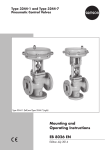
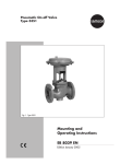
Pneumatic Control Valves
Type 3241-1 and Type 3241-7
Type 3241-1
Type 3241-7
Fig. 1 · Type 3241 Valve with Type 3271 Actuator and with Type 3277 Actuator
Mounting and
Operating Instructions
EB 8015 EN
Edition September 2009
Contents
Contents
1
2
2.1
2.2
2.3
3
3.1
3.2
3.3
3.4
4
5
5.1
5.1.1
5.1.2
5.2
5.2.1
5.2.2
5.2.3
5.2.4
5.2.5
5.3
6
6.1
6.2
7
8
Page
Design and principle of operation . . . . . . . . . . . . . . . . . . . . 4
Assembling valve and actuator . . . . . . . . . . . . . . . . . . . . . . 4
Assembly and adjustment . . . . . . . . . . . . . . . . . . . . . . . . 4
Pretensioning springs in actuator version “Actuator stem extends”. . . . . 7
Valve and actuator with different rated travels . . . . . . . . . . . . . . 8
Installation . . . . . . . . . . . . . . . . . . . . . . . . . . . . . . . 9
Mounting position. . . . . . . . . . . . . . . . . . . . . . . . . . . . 9
Signal pressure line . . . . . . . . . . . . . . . . . . . . . . . . . . . 9
Strainer, bypass . . . . . . . . . . . . . . . . . . . . . . . . . . . . 9
Test connection . . . . . . . . . . . . . . . . . . . . . . . . . . . . . 9
Operation . . . . . . . . . . . . . . . . . . . . . . . . . . . . . . . 9
Maintenance – Replacing parts . . . . . . . . . . . . . . . . . . . . . 10
Standard valve version. . . . . . . . . . . . . . . . . . . . . . . . . 11
Stuffing box packing. . . . . . . . . . . . . . . . . . . . . . . . . . 11
Seat and/or plug . . . . . . . . . . . . . . . . . . . . . . . . . . . 12
Valve with extension bonnet or metal bellows seal . . . . . . . . . . . 13
Stuffing box packing. . . . . . . . . . . . . . . . . . . . . . . . . . 13
Plug. . . . . . . . . . . . . . . . . . . . . . . . . . . . . . . . . . 13
Seat. . . . . . . . . . . . . . . . . . . . . . . . . . . . . . . . . . 15
Metal bellows . . . . . . . . . . . . . . . . . . . . . . . . . . . . . 15
Reassembly . . . . . . . . . . . . . . . . . . . . . . . . . . . . . . 16
Replacing the collar or seal . . . . . . . . . . . . . . . . . . . . . . 16
Material identification . . . . . . . . . . . . . . . . . . . . . . . . . 18
Identification marks . . . . . . . . . . . . . . . . . . . . . . . . . . 18
Seat code . . . . . . . . . . . . . . . . . . . . . . . . . . . . . . . 19
Description of nameplates . . . . . . . . . . . . . . . . . . . . . . . 20
Customer inquiries . . . . . . . . . . . . . . . . . . . . . . . . . . 21
These Mounting and Operating Instructions apply also to Type 3246 Globe Valve
(Class 150 and 300) in conjunction with Data Sheet T 8046-1 EN.
Note! Non-electrical control valves which do not have a valve body lined with an insulating
material coating do not have their own potential ignition source according to the risk assessment in the rare incident of an operating fault, corresponding to EN 13463-1: 2001 paragraph 5.2, and therefore do not fall within the scope of the European Directive 94/9/EC.
Refer to paragraph 6.3 of EN 60079-14:1977 VDE 0165 Part 1 concerning connection to
equipotential bonding system.
2
EB 8015 EN
Safety instructions
General safety instructions
4 The control valve may only be mounted, started up or serviced by fully
4
4
4
trained and qualified personnel, observing the accepted industry codes and
practices. Make sure employees or third persons are not exposed to any
danger. All safety instructions and warnings in these mounting and
operating instructions, particularly those concerning assembly, start-up and
maintenance, must be observed.
The control valves fulfill the requirements of the European Pressure
Equipment Directive 97/23/EC. Valves with a CE marking have a
declaration of conformity that includes information about the applied
conformity assessment procedure. The declaration of conformity is available
on request.
For appropriate operation, make sure that the control valve is only used in
areas where the operating pressure and temperatures do not exceed the
operating values which are based on the valve sizing data submitted in the
order. The manufacturer does not assume any responsibility for damage
caused by external forces or any other external influence! Any hazards
which could be caused in the control valve by the process medium,
operating pressure, signal pressure or by moving parts are to be prevented
by means of the appropriate measures.
Proper shipping and appropriate storage are assumed.
Caution!
4 For installation and maintenance work on the valve, make sure the relevant
4
4
section of the pipeline is depressurized and, depending on the process
medium, drained as well. If necessary, allow the control valve to cool down
or warm up to reach ambient temperature prior to starting any work on the
valve.
Prior to performing any work on the valve, make sure the supply air and
control signal are disconnected or blocked to prevent any hazards that could
be caused by moving parts.
Special care is needed when the actuator springs are preloaded. These
actuators are labeled correspondingly and can also be identified by three
long bolts at the bottom of the actuator. Prior to starting any work on the
valve, you must relieve the compression from the preloaded springs.
EB 8015 EN
3
Design and principle of operation
1
Design and principle of opera- Actuator stem retracts
When the signal pressure is reduced or the
tion
The Type 3241-1 and Type 3241-7 Pneumatic Control Valves consist of a Type 3241
single-seated Globe Valve and either a
Type 3271 or Type 3277 Pneumatic Actuator.
Thanks to the modular design, the actuators
can be exchanged, and the standard version
of the valve can be supplemented to form a
version with extension bonnet or metal bellows seal.
In the micro-flow valve version, a micro-trim
element is installed in the valve body instead
of the usual seat-plug assembly.
The process medium flows through the valve
in the direction indicated by the arrow. The
position of the plug (3) determines the flow
through the valve seat (2). The position of
the plug (3) is changed by the signal pressure acting on the diaphragm of the actuator (bench range). Plug (3) and actuator
stem (8.1) are connected by the stem connector (7) and sealed by the spring-loaded
ring packing (4.2).
Fail-safe position
The control valve provides two different
fail-safe positions depending on the arrangement of the springs in the actuator:
Actuator stem extends
When the signal pressure is reduced or the
power supply or signal fails, the springs
move the actuator stem downwards and
close the valve.
When the signal pressure increases again,
the valve opens acting against the force of
the springs.
4
EB 8015 EN
power supply or signal fails, the springs
move the actuator stem upwards and open
the valve.
When the signal pressure increases again,
the valve closes acting against the force of
the springs.
2
Assembling valve and actuator
The basic pneumatic actuator can be replaced by an electric actuator or a pneumatic actuator with additional handwheel.
A pneumatic actuator (with or without
handwheel) can be exchanged for another
pneumatic actuator in a different size.
If, in the valve-actuator assembly, the travel
range of the actuator is larger than the
travel range of the control valve, the actuator springs are preloaded by the manufacturer so that the travels match.
2.1
Assembly and adjustment
If the valve and actuator have not been
pre-assembled by the manufacturer, or if the
actuator of a valve is to be replaced by an
actuator of another type or another size,
proceed as described below.
1. Unscrew the lock nut (6.2) and stem connector nut (6.1).
Firmly press the plug together with the
plug stem into the seat ring. Make sure
the large V-shaped port of the V-port
plug faces towards the valve outlet.
Thread the stem connector nut and lock
nut downwards.
Assembling valve and actuator
Type 3271 Actuator
1.
Valve body
1.1 Nuts
1.2 Gasket
8
2
Seat
3
Plug
4.1 Spring
4.2 Packing
5
5
8.2
Valve bonnet
5.2 Threaded bushing
5.3 Travel indicator scale
5.3
8.1
7
6.1
1.1
1.2
6.2
1
5.2
6
6
6.1
6.2
6.3
Plug stem
Stem connector nut
Lock nut
Yoke
(DN 200 to DN 300)
7 Stem connector
8 Actuator
8.1 Actuator stem
8.2 Nut
4.2
4.1
2
3
Type 3241 Valve
Micro-trim element
15 Plug stem
16 Valve plug
17 Seat body
18 Spring
19 Seat nut
15
16
17
18
19
Fig, 2 · Sectional drawings
EB 8015 EN
5
Assembling valve and actuator
Type 3277 Actuator
8
6.3
8.1
5.3
8.2
6.1
6.2
7
1
1.1
1.2
2
3
4.1
4.2
5
5.2
5.3
6
6.1
6.2
6.3
7
Valve body
Nuts
Gasket
Seat
Plug
Spring
Packing
Valve bonnet
Threaded bushing
Travel indicator scale
Plug stem
Stem connector nut
Lock nut
Yoke (DN 200 to DN 300)
Stem connector
8 Actuator
8.1 Actuator stem
8.2 Nut
Fig. 3 · Sectional drawings of Type 3241-7 and valve body DN 200 to DN 300
6
EB 8015 EN
5.2
6
4.2
4.1
1.1
5
1.2
3
2
1
Assembling valve and actuator
2. Remove the stem connector clamps (7)
and the ring nut (8.2) from the actuator
(8). Slide the ring nut over the plug stem.
3. Place actuator onto the valve bonnet (5)
and secure with the ring nut (8.2).
4. Read bench range (or bench range with
pre-loaded springs) and fail-safe action
from the actuator's nameplate (e.g. 0.2
to 1 bar and "Actuator stem extends").
The lower value of the bench range
(0.2 bar) corresponds to the lower bench
range value to be adjusted; the upper bench
range value (1 bar) corresponds to the
upper bench range value. The fail-safe action "Actuator stem extends" (FA) or "Actuator stem retracts" (FE) is indicated on the
Type 3271 Actuator. The Type 3277 Actuator bears the corresponding symbol.
5. For actuators with "Actuator stem extends", apply a signal pressure to the
lower diaphragm chamber which corresponds to the lower bench range value
(e.g. 0.2 bar).
For actuators with "Actuator stem retracts", apply a signal pressure to the
upper diaphragm chamber which corresponds to the upper bench range value
(e.g. 1 bar).
6. Thread down the stem connector nut
(6.1) by hand until it makes contact with
the actuator stem (8.1). Then, turn it another 1/4 turn and secure this position
with the lock nut (6.2).
7. Position the stem connector clamps (7)
and screw tight. Align the travel indicator scale (5.3) with the tip of the stem
connector.
Note on disassembling an actuator!
Before disassembling an actuator with
fail-safe action "Actuator stem extends" and
particularly an actuator with preloaded
springs, apply a pressure to the lower signal
pressure connection that slightly exceeds the
lower bench range value (see nameplate of
the actuator), so that you can loosen the ring
nut (8.2).
2.2
Pretensioning springs in
actuator version “Actuator
stem extends”
To achieve a greater positioning force, the
springs in actuators with "Actuator stem extends" can be preloaded with up to 12.5 %
(actuator sizes 120 and 240 cm²) or up to
25 % (350 cm² and higher) of their travel or
bench range.
Example:
If the springs are preloaded with, for example, 0.1 bar for a bench range of 0.2 to
1 bar, the bench range is shifted by 0.1 bar
to result in a bench range of 0.3 to 1.1 bar
(0.1 bar corresponds to a preload of
12.5 %).
When adjusting the valve, the lower bench
range is to be set to 0.3 bar. Make sure the
new bench range of 0.3 to 1.1 bar is indicated on the nameplate as the bench range
with preloaded springs!
EB 8015 EN
7
Assembling valve and actuator
2.3
Valve and actuator with
different rated travels
Actuator version "Actuator stem extends"
Note!
Valves that have a travel smaller than the
rated travel of the actuator always need to
use preloaded springs.
Example:
Valve DN 100 with 30 mm rated travel and
1400 cm² actuator with 60 mm rated travel,
0.4 to 2 bar bench range.
1. Set the signal pressure required for
tensioning the springs above the signal
pressure of 1.2 bar (1.2 to 2 bar range)
which corresponds to the mid actuator
travel (30 mm) to 1.6 bar.
2. Thread stem connector nut (6.1) until it
touches the actuator stem.
3. Secure the position with lock nut and attach stem connector as described in section 2.1.
4. Enter the 1.6 to 2.4 bar bench range
valid for the mounted valve on the
nameplate of the actuator.
8
EB 8015 EN
Actuator version "Actuator stem retracts"
Note!
The springs in the actuator version “Actuator
stem retracts” cannot be preloaded!
If a valve is to be attached to a larger actuator (rated travel of actuator larger than the
rated travel of the valve), just the first half of
the bench range of the actuator can be
used.
Example:
Valve DN 100 with 30 mm rated travel and
1400 cm² actuator with 60 mm rated travel,
0.4 to 1 bar bench range:
A useable bench range of 0.2 to 0.6 bar is
available for the half valve range.
Caution!
Actuators which have been
preloaded by the manufacturer
without an attached valve are
marked with a label.
In addition, you will notice three
extended bolts on the bottom
diaphragm case. They enable you to
evenly relieve the compressed
springs when disassembling the
actuator.
Installation
3
Installation
3.1
Mounting position
The valve can be mounted in any desired
position. However, vertical installation with
the actuator pointing upwards is preferable
for valves in nominal size DN 100 or larger
to facilitate maintenance.
For valves with extension bonnet or metal
bellows seal, or for actuators weighing more
than 50 kg, mount a suitable support or suspension for the actuator.
Note!
The valve must be installed with the least
amount of vibrations possible and without
any stress.
Piping design
To allow the control valve to work properly,
the pipeline upstream and downstream of
the valve should be straight and free of obstructions for a length of at least 6 times the
pipe diameter (DN).
Contact SAMSON if this length cannot be
met during installation.
Clean out the pipeline thoroughly prior to installing the valve.
Note!
Valves that should meet the requirements of
NACE MR 0175 standard should not be insulated.
3.2
Signal pressure line
Connect the signal pressure line to the lower
diaphragm case for valves with actuator
version "Actuator stem extends" and to the
upper diaphragm case for valves with actu-
ator version "Actuator stem retracts".
The lower signal pressure connection of the
Type 3277 Actuator is located at the side of
the yoke of the lower diaphragm case.
3.3
Strainer, bypass
We recommend you to install a SAMSON
Type 2 Strainer upstream of the valve body.
We also recommend to install a shut-off
valve both upstream of the strainer and
downstream of the valve, as well as a bypass, so that you do not need to shut down
the plant for maintenance.
3.4
Test connection
If there is a test connection (G 1/8) at the
upper flange of a valve version with metal
bellows seal (Fig. 6), you can check the
tightness of the bellows there.
Particularly for liquids and vapors, we recommend you to install a suitable leak indicator at the test connection, such as a contact
pressure gauge, an outlet into an open vessel or an inspection window.
4
Operation
(e.g. reversing the fail-safe action of the actuator etc.)
For details concerning operation, see
Mounting and Operating Instructions
EB 8310 EN for the Type 3271 Pneumatic
Actuator and
EB 8311 EN for the Type 3277 Pneumatic
Actuator.
EB 8015 EN
9
Maintenance – Replacing parts
5
Maintenance – Replacing parts
The control valve is subject to natural wear,
especially at the seat, plug and packing.
Depending on the application, the valve
needs to be checked regularly to prevent
against possible failures.
If leakage occurs, this could be caused by a
damaged packing or a defective metal bellows.
If the valve does not seal properly, the tight
shut-off may be impeded by dirt or other impurities caught between the seat and plug,
or by damaged seating surfaces.
Remove the parts, clean them thoroughly
and replace them with new ones, if necessary.
Note!
When mounting the bonnet, the large
V-shaped port of the V-port plug must face
towards the valve outlet.
Caution!
Before servicing or disassembling the
control valve, depressurize the concerned section of the plant and drain
it, if necessary, depending on the
medium used. Switch off the signal
pressure for the actuator and remove
the signal pressure line. As valves
are not free of cavities, there might
still be residual medium in the valve.
This applies, in particular, for valve
versions with extension bonnet and
metal bellows seal.
10
EB 8015 EN
Caution!
On performing any work on the valve, first
shut off the signal pressure, disconnect the
signal pressure line and remove the actuator.
Note!
Suitable seat and special tools as well as the
appropriate tightening torques required for
installation are listed in EB 029 EN (formerly
WA 029 EN). The instructions can be
viewed on the Internet at
www.samson.de/pdf_en/e00290en.pdf.
Removing the actuator:
1. Before disassembling an actuator with
fail-safe action "Actuator stem extends"
and particularly an actuator with
preloaded springs, apply a pressure to
the lower signal pressure connection that
slightly exceeds the lower bench range
value (see nameplate), so that you can
remove the ring nut (8.2). Remove the
stem connector clamps (7) and the ring
nut (8.2).
2. Remove the actuator from the valve bonnet.
Maintenance – Replacing parts
5.1
Standard valve version
4. Pull all packing parts out of the packing
chamber using a suitable tool. Replace
damaged parts. Clean packing chamber
thoroughly.
5. Remove the gasket (1.2) and carefully
clean sealing faces in the valve body
and on the bonnet.
6. Apply lubricant (order no. 8150-0111)
to all the packing parts and the plug
stem (6).
7. Slide the plug stem with plug into the
valve bonnet.
5.1.1 Stuffing box packing
1. Remove the body nuts (1.1) as well as
the valve bonnet (5) together with the
plug stem and plug from the body.
2. Unscrew the stem connector nut and lock
nut (6.1 and 6.2) from the plug stem.
3. Screw the threaded bushing (5.2) out of
the stuffing box. Pull the plug stem together with the plug out of the valve
bonnet.
5.2
5.2
4.2
4.2
4.3
4.1
4.3
4.1
4 Packing
4.1 Spring
4.2 PTFE ring packing or
packing rings
4.3 Washer
5 Bonnet
5
6
6
6.3
5
5.2 Threaded bushing
6 Plug stem
6.3 Yoke
Fig. 4 · Stuffing box packing
EB 8015 EN
11
Maintenance – Replacing parts
8. Insert new flat gasket (1.2) into the
body. Carefully place the valve bonnet
onto the valve body, making sure that
the large V-shaped port of the V-port
plug faces towards the valve outlet.
Secure with nuts (1.1).
9. Carefully slide the packing parts over the
plug stem into the packing chamber.
Keep the proper order. Screw in the
threaded bushing (5.2) and tighten.
10. Loosely screw the lock nut (6.2) and stem
connector nut (6.1) onto the plug stem.
11. Mount the actuator and adjust the upper
and lower bench range values as described in section 2.1.
5.1.2 Seat and/or plug
We recommend you to also replace the
packing (4.2) when exchanging the seat
and plug.
To exchange the packing, proceed as described in section 5.1.1.
remachined until dimension x is reached,
and if the seat bore exceeds 12 mm. For
seat bores of 63 mm and larger, the entire sealing ring can be exchanged, if
necessary (the plug parts are screwed together).
Seat:
4 Unscrew the seat (2) using the appropri-
ate seat wrench (see EB 029 EN).
Apply lubricant (order no. 8150-0119)
to the thread and sealing cone of the
new seat (or possibly the old seat when it
has been reworked or thoroughly
cleaned) and screw it in.
Micro-trim insert
In this version, the complete micro-trim element (Fig. 2) can be unscrewed from the
valve body using a socket wrench (width
across flats 27) and disassembled for cleaning. If individual parts are damaged, exchange the entire micro-trim element.
Plug:
4 Remove the old plug and replace it with
x
w
a new plug with plug stem. It may be
possible to use the old plug again, provided it has been remachined properly.
Make sure the plug is installed in the
correct direction. Apply lubricant (order
no. 8150-0111) to the plug stem before
installation.
R0
Remaching the plug
4 Slight damage at the facing of the plug
can be eliminated by re-turning it on a
lathe. Soft-sealing plugs can only be
12
EB 8015 EN
.3
Seat bore
x [mm]
12
0.5
24...48
1.0
6...80
2.0
100...200
2.5
30
˚
Fig. 5 · Plug with soft sealing
Maintenance – Replacing parts
5.2
Valve with extension bonnet
or metal bellows seal
5.2.1 Stuffing box packing
1. Remove the stem connector nut and lock
nut (6.1 and 6.2) from the plug stem extension (6.3). Unscrew the threaded
bushing (5.2) out of the stuffing box.
2. Remove nuts (5.4) and carefully lift the
bonnet (5) over the plug stem extension.
3. Pull all stuffing box parts out of the packing chamber using a suitable tool.
Replace damaged parts. Clean packing
chamber thoroughly.
4. Remove the gasket (5.5) in the intermediate piece (12) and carefully clean the
sealing faces.
5. Apply lubricant (order no. 8150-0111)
to all the packing parts and the plug
stem (6).
6. Insert new gasket (5.5) in the intermediate piece. Carefully place the bonnet
over the plug stem extension onto the
bonnet and secure with nuts (5.4).
7. Carefully slide the stuffing box parts over
the plug stem extension into the packing
chamber. Make sure to keep the proper
order. Screw in the threaded bushing
(5.2) and tighten.
8. Loosely screw the lock nut (6.2) and stem
connector nut (6.1) onto the plug stem.
9. Mount the actuator and adjust the upper
and lower bench range values as described in section 2.1.
5.2.2 Plug
When exchanging the plug, check the packing (4.2) or, preferably, replace it as described in section 5.2.1.
Nominal sizes DN 15 to DN 150: To unscrew the plug (6) from the plug stem extension (6.3), screw two nuts onto the protruding thread of the extension to hold the plug
stem extension in place.
Caution!
To prevent damage to the version with the
bellows seal (no bellows in the version with
extension bonnet), make sure no torque is
transmitted to the bellows, which is connected to the intermediate piece. We recommend you to use a clamping tool (see
EB 029 EN).
1. Remove the nuts (1.1).
2. Remove the intermediate piece (12) together with the plug stem extension, plug
stem and plug from the valve body.
3. Remove gasket (1.2) and carefully clean
the sealing faces in the valve body and
on the intermediate piece.
4. Use an appropriate wrench to hold the
nuts stationary, which are screwed onto
the plug stem extension. Clamp the plug
stem using a suitable tool and screw it
out of the plug stem extension.
Caution! Do not twist the plug stem extension with the welded-on bellows!
5. Apply lubricant (order no. 8150-0111)
to the end of the plug stem (6) of the
new or old, reworked plug (3).
EB 8015 EN
13
Maintenance – Replacing parts
1.1 Nuts
1.2 Gasket
3 Plug
3.5 Tension ring
5
3.6 Flange
6.3 Plug stem extension
6.4 Washers
6.1
3.7 Screws
4.2 Packing
6.5 Nut (DN 15 to DN 150)
6.6 Metal bellows
6.2
4.2
6 Plug stem
6.1 Stem connector nut
6.2 Lock nut
5.2
6.3
5.5
11
5.4
12
5
Bonnet
6.7 Seal
5.2 Threaded bushing 6.8 Seal (DN 200 to DN 300)
5.4 Bolts
11 Test connection
5.5 Gasket
12 Intermediate piece
6.5
6.6
DN 15 to DN 150
(forged valve body)
1.1
4.2
6.4
6
5
DN 200 to DN 300
(with flow divider)
1.2
6
11
5.4
6.8
6.7
12
3.7
3.6
3.5
3
Fig. 6 · Versions with metal bellows seal and extension bonnet
14
EB 8015 EN
6.6
1.1
Maintenance – Replacing parts
4
Check whether the two washers (6.4)
are still in the plug stem extension (6.3).
Screw the plug stem firmly into the plug
stem extension (6.3); tightening torque is
50 Nm for Ø 10 mm and 80 Nm for
Ø 16 mm.
To complete assembly, refer to section
5.2.5.
Nominal sizes DN 200 to DN 300:
1. Remove the nuts (1.1).
2. Remove the intermediate piece (12) together with the plug stem and plug from
the valve body.
3. Remove gasket (1.2) and carefully clean
the sealing faces in the valve body and
on the intermediate piece.
4. Remove the hexagon head screws (3.7),
tension ring (3.5) and flange (3.6).
5. Unscrew the plug from the plug stem. To
do so, use a suitable tool to hold the
plug stem in place, so that the metal bellows, which is welded onto the plug
stem, cannot be twisted.
6. Screw a new plug with tension ring and
flange to the plug stem.
To complete assembly, refer to section
5.2.5.
In the version with extension bonnet, there
are no parts 3.5, 3.6 and 3.7. Plug (3) and
plug stem(6) form one piece.
4
5.2.4 Metal bellows
Nominal sizes DN 15 to DN 150:
1. Unscrew the plug (3) together with the
plug stem (6) from the plug stem extension (6.3) as described for replacing the
seat in section 5.2.2.
2. Unscrew the nut (6.5) using a SAMSON
socket wrench (see EB 029 EN).
3. Pull the plug stem extension with the
welded-on metal bellows (6.6) out of the
intermediate section (12).
4. Clean the sealing faces on the intermediate piece.
5. Insert a new plug into the intermediate
piece and screw down the nut (6.5).
Caution!
Do not twist the metal bellows!
6. Check whether both washers (6.4) are
still in the plug stem extension (6.3).
Apply lubricant (order no. 8150-0111)
to the thread of the plug stem and firmly
screw the plug stem into the plug stem
extension (6.3) with a tightening torque
of 50 Nm for a plug stem diameter of
10 mm and 80 Nm for a diameter of
16 mm.
5.2.3 Seat
Replace the seat (2) as described in section
5.1.2.
EB 8015 EN
15
Maintenance – Replacing parts
Nominal sizes DN 200 to DN 300:
5.3
1. Unscrew the plug (3) from the plug stem
as described in section 5.2.2.
Pull the plug stem (6) together with the
metal bellows (6.6) upwards, out of the
intermediate piece (12).
2. Replace the seal (6.7) and insert a new
plug stem with metal bellows (6.6).
3. Screw on the plug and secure with the
tension ring (3.5), flange (3.6) and
screws (3.7).
For version with pressure-balanced plug:
5.2.5 Reassembly
1. Insert new gasket (1.2) into the valve
body. Place the intermediate piece (12)
onto the valve body (1), making sure
that the large V-shaped port of V-port
plug faces towards the valve outlet.
Secure with nuts (1.1).
2. Insert new gasket (5.5) into the intermediate piece. Place the valve bonnet (5)
onto the intermediate piece and secure
with bolts (5.4) and nuts. Observe the
tightening torques specified in
EB 029 EN.
3. Tighten the threaded bushing (5.2).
4. Loosely screw the lock nut (6.2) and stem
connector nut (6.1) onto the plug stem
extension (6.3) or plug stem.
5. Mount the actuator and adjust the upper
and lower bench range values as described in section 2.1.
16
EB 8015 EN
Replacing the collar or seal
1. Unscrew the stem connector nut and lock
nut (6.1 and 6.2) from the plug stem.
2. Remove the body nuts (1.1) and carefully lift off the valve bonnet (5) with plug
stem (6).
3. Screw the threaded bushing (5.2) out of
the stuffing box. Pull plug stem and plug
(3) out of the bonnet.
4. Remove gasket (1.2) and carefully clean
the sealing faces in the valve body and
on the bonnet.
Nominal size DN 40:
5. Pull the packing (4.2), washer (4.3) and
spring (4.1) out of the packing chamber
using an appropriate tool. Replace damaged parts.
6. Push out the bushing (3.2) and replace
the collar (3.1). Clean the packing
chamber thoroughly.
7. Apply lubricant (order no. 8150-0111)
to the bushing (3.2) and push it in
again.
8. Also apply lubricant to the packing
parts, plug stem (6) and the contact
faces of the collar (3.1).
9. Insert the plug stem and plug into the
valve bonnet.
Maintenance – Replacing parts
Completion of reassembly:
11. Slide the stuffing box parts over the plug
stem into the packing chamber. Make
sure to keep the proper order.
12. Screw in the threaded bushing (5.2) and
tighten.
13. Loosely screw the lock nut (6.2) and stem
connector nut (6.1) onto the plug stem.
10. Insert new gasket (1.2) into the valve
body. Carefully place the valve bonnet
on the valve body, making sure that the
large V-shaped port of V-port plug faces
towards the valve outlet. Secure with
nuts (1.1). Observe the tightening
torques specified in EB 029 EN.
3.1
3.3
3.4
6
3.1
3.2
3.1
6
3.2
3.4
DN 40
6
DN 50
DN 65 and DN 80
3.1
3.1
3.3
3.4
3.3
3.4
6
DN 100 to DN 150
3
3.1
3.2
3.3
3.4
6
Plug
Collar, seal
Bushing
Washer, ring
Screw
Plug stem
DN 200 to DN 300
Fig. 7 · Pressure-balanced plug
EB 8015 EN
17
Material identification
14. Mount the actuator and adjust the upper
and lower range values as described in
section 2.1.
Nominal sizes DN 50 to DN 150
5. Remove screw (3.4) with its locking device and washer (3.3). Replace collar
(3.1).
6. Insert washer (3.3). Thread down the
screw (3.4) with its locking device.
7. Apply lubricant (order no. 8150-0111)
to the packing parts, plug stem (6) and
contact faces of the collar (3.1).
8. Insert the plug stem and plug into the
valve bonnet.
Complete reassembly as described for
DN 40, steps 10 to 14.
4
Nominal sizes DN 200 to DN 300:
5. Remove the screw (3.4) with its locking
device.
6. Lift off the ring (3.3) and replace collar
or seal (3.1).
7. Insert ring (3.3). Thread down screw
(3.4) and its locking device.
8. Apply lubricant (order no. 8150-0111)
to the packing parts, plug stem (6) and
contact faces of the collar (3.1).
9. Insert the plug stem and plug into the
valve bonnet.
Complete reassembly as described for
DN 40, steps 10 to 14.
4
6
Material identification
The trim material of older valves is indicated
by an identification mark on the guide bushings, seat and plug as described below.
A detailed trim material identification has
been introduced using a seat code on the
nameplate. Refer to section 7 (pos. 13,
MExx).
6.1
Identification marks
Guide bushing (groove on plane face)
4 No groove: 1.4305
4 Sharp recessed groove: 1.4571
4 Flat recessed groove: Hastelloy
Seat
The material number according to DIN is either stamped or engraved on the seat.
4 Stellited seats are marked by a stamped-on "st".
Plug
Groove below the plug stem thread:
4 No groove: 1.4006
4 Sharp recessed groove: 1.4571
4 Two sharp recessed grooves: 1.4301
4 Flat recessed groove: Hastelloy
4 When other materials are used, either
the material number or its designation is
engraved on the plug.
The Kvs coefficient and characteristic are
engraved on the plug.
4 Stellited plugs are marked by an
engraved "st".
18
EB 8015 EN
Material identification
6.2
Seat code
Trim material identification on the nameplate, pos. 13, MExx (xx = seat code).
Seat code
Trim material
01
1.4006
02
CrNiMo steel
03
1.4301
04
Stellite 6B (CrNiMo steel,
entire seat bore stellited)
05
Stellite 6B (seat of solid
Stellite)
10
1.4112
11
1.4306
12
1.4462
13
1.4539
14
1.7362 V
15
2.4360
16
2.4602
17
2.4605
18
2.4610
19
2.4617
20
2.4681
21
3.7035
22
3.7235
Dimensions and weights
Refer to the associated Data Sheet for dimensions and weights of the valve versions:
Type 3241 - DIN version
T 8015 EN
Type 3241 - ANSI version
T 8012 EN
Type 3246 - Class 150/300 T 8046-1 EN
EB 8015 EN
19
Description of nameplates
Description of nameplates
SAMSON
1
2
3 -4
5
7
8
9
10
11 12
13
H
14
15
1
CE marking or "Art. 3, Abs.3"
(see article 3, § 3 of PED), where applicable
2
Identification no. of notified body, fluid group and
category, where applicable
Type designation
Modification index of valve
Material
Year of manufacture
Nominal size: DIN: DN, ANSI: NPS
Permissible excess pressure at room temperature
DIN: PN, ANSI: CL
Order number with modification index
Position of item in order
Flow coefficient:
DIN: KVS, ANSI: Cv
Characteristic:
% equal percentage, Lin linear,
DIN: A/Z quick opening, ANSI: O/C
Sealing:
MExx metal (see section 6.2),
ST stellited, Ni nickel-plated
PT soft sealing with PTFE,
PK soft sealing with PEEK
Pressure-balanced: DIN: D, ANSI: B
I or III flow divider
3
4
5
6
7
8
9
10
11
12
13
14
15
Fig. 8 · Valve nameplate (left) and actuator nameplates (right)
20
EB 8015 ENEB 8015 EN
SAMSON
6
5
1
F
2
6
3
V
4
7
Made in
Germany
7
1
Type designation
2
3
4
Modification index
Effective diaphragm area
Fail-safe action:
FA Actuator stem extends
FE Actuator stem retracts
Travel
Bench range (spring range)
Bench range with preloaded springs
5
6
7
SAMSON
Model - No.
1
Serial - No.
Pneum. Stellantrieb
3
Pneum. actuator
Servo - monteur pneum.
Federbereich
Spring range
Plage des ressorts
Stelldruckbereich
Signal pressure range
Plage avec précontrainte
Hub
cm² Stroke
Course
mm
bar
bar
Zuluft max. 6 bar Begrenzt auf
Air supply 90 psi Up to
Air d' alimentation Limité à
Made in France
bar
Customer inquiries
8
Customer inquiries
If you encounter any problems, please submit the following details:
4 Order number
4 Type, product number, nominal size and
version of the valve
4 Pressure and temperature of the process
medium
4 Flow rate in m³/h
4 Bench range of the actuator (e.g. 0.2 to
1 bar)
4 Has a strainer been installed?
4 Installation drawing
EB 8015 EN
21
22
EB 8015 EN
EB 8015 EN
23
EB 8015 EN
S/Z 2010-09
SAMSON AG · MESS- UND REGELTECHNIK
Weismüllerstraße 3 · 60314 Frankfurt am Main · Germany
Phone: +49 69 4009-0 · Fax: +49 69 4009-1507
Internet: http://www.samson.de


![United StiltBS Patent [19] [11] Patent Number: 5,025,556](http://vs1.manualzilla.com/store/data/006008181_1-2c5f49b6565f7d3a6ea1501cb683eb1f-150x150.png)