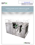
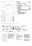
1
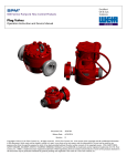
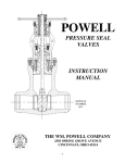
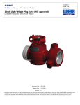
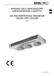
SPM® Well Service Pumps & Flow Control Products Automated Relief Valve Control (A.R.C.) System Operation Instruction and Service Manual Part Number: 2A38151 Release Date: 10/31/2013 Revision: B Copyright © 2013, S.P.M. Flow Control, Inc.. All rights reserved. S.P.M. Flow Control, Inc. is the owner of the copyright and all confidential information in this document, which must not be copied in whole or in part, in any form or by any means, and the information in it must not be used for any purpose other than the specific purpose for which it has been provided without the prior written consent of the copyright owner. SPM, SAFETY IRON, SAFETY HAMMER, SUR-DROP, DESTINY, STAMPEDE, VERIBAND, DURALAST and GLADIATOR are trademarks and/or registered trademarks of S.P.M. Flow Control, Inc.. WEIR is a trademark and/or registered trademark of Weir Engineering Services Limited. Certain features of some of the products disclosed in this document may be protected worldwide by patents pending and registered in the name of S.P.M. Flow Control, Inc.. Part Number: 2A38151 Release Date: 10/31/2013 Revision: B THE FOLLOWING ICONS DENOTE IMPORTANT INFORMATION WITHIN THIS MANUAL. GENERAL INFORMATION INSTALLATION AND OPERATION MAINTENANCE AND REPAIR SALES AND SUPPORT NOTE CAUTION WARNING/ DANGER 2 Part Number: 2A38151 Release Date: 10/31/2013 Revision: B SPM® PRODUCT SAFETY GUIDE IMPORTANT SAFETY INFORMATION ENCLOSED. READ THIS OPERATING AND MAINTENANCE INSTRUCTIONS MANUAL BEFORE OPERATING PRODUCT. THIS INFORMATION MUST BE AVAILABLE TO ALL PRESONNEL THAT WILL OPERATE AND MAINTAIN EQUIPMENT. FAILURE TO READ, UNDERSTAND AND FOLLOW THE OPERATING AND MAINTENANCE INSTRUCTIONS MANUAL COULD RESULT IN SEVERE PERSONAL INJURY OR DEATH! Most SPM® products generate, control or direct pressurized fluids; therefore, it is critical that those who work with these products be thoroughly trained in their proper application and safe handling. It is also critical that these products be used and maintained properly!! WARNING: MISUSE, SIDE LOADING, IMPROPER MAINTENANCE, OR DISASSEMBLY UNDER PRESSURE CAN CAUSE SERIOUS INJURY OR DEATH! The following information is given in good faith and should aid in the safe use of SPM® products. This information is not meant to replace existing user safety policies or practices. SPM products contain elastomer seals and are not intended to provide functionality in the event of a fire. Personal Responsibilities: 1. NEVER hammer on any component when pressure is present. Hammering on any part or component may also cause foreign material or steel slags to become airborne. 2. DO NOT touch hot surfaces. It is your own responsibility to protect against a burn injury. 3. YOU MUST wear proper Personal Protective Equipment (PPE) when working on SPM® flow control products. 4. YOU MUST use the proper tools when servicing the A.R.C. System. It is a personal responsibility to be knowledgeable and trained in the use and handling of tools for all maintenance of the A.R.C. System. 3 Part Number: 2A38151 Release Date: 10/31/2013 Revision: B On Location: 1. NEVER weld, braze or heat any part of the system. If accessories must be attached, consult the Weir Oil & Gas factory prior to installation. 2. NEVER allow anyone but a trained service technician who is qualified to work on the equipment perform any repairs or service (even routine maintenance) on the A.R.C. System. All such service and repairs must be supervised by qualified management personnel or returned to Weir Oil & Gas for service. 3. NEVER use anything but SPM® replacement parts. Failure to do so will void the warranty as well put you in risk of SERIOUS INJURY OR DEATH! 4. DO NOT TAMPER WITH THE POP-OFF PRESSURE SETTINGS. Tampering could result in serious injury or death. The A.R.C. System has built in settings to ensure that the desired pop-off pressure cannot exceed 15,000 PSI. 5. ALWAYS PROPERLY CLEAN AND MAINTAIN The communication lines and nitrogen hoses should be properly cleaned and maintained before and after every fracturing job. This will ensure their longevity and effectiveness during operation. 6. ALWAYS REPLACE any worn or damaged cables and hoses. 7. ALWAYS DO A VISUAL INSPECTION of the A.R.C. System before each use. Fix any leaking seals, broken bolts, leaking hoses or improperly tightened parts before using it. Special Warnings: 1. MODIFICATIONS. Modifications to, unauthorized repair of any part of a SPM® product, and use of components not qualified by SPM®, can lead to damage or failure the A.R.C. system and even SERIOUS INJURY OR DEATH! 2. THREADS. All SPM® threaded components are right hand threaded unless specifically designated otherwise. Any turning in the counterclockwise direction will loosen the assembly. 3. CLEANING AND LUBRICATION. All products should be properly cleaned, greased or oiled after each use and inspected prior to each use. 4 Part Number: 2A38151 Release Date: 10/31/2013 Revision: B TABLE OF CONTENTS SECTION I: GENERAL INFORMATION ............................................................................................................. 6 THIS SERVICE MANUAL COVERS: .............................................................................................................................. 6 REPLACEMENT PARTS: ........................................................................................................................................... 6 BRIEF DESCRIPTION/FEATURES: ............................................................................................................................... 7 BRIEF OPERATIONS SETUP: ..................................................................................................................................... 7 PRODUCT OVERVIEW: ........................................................................................................................................... 8 SECTION II: COMPONENT DESCRIPTION ....................................................................................................... 9 CONTROL ASSEMBLY ............................................................................................................................................ 9 CONTROL BOX ................................................................................................................................................... 9 MOUNTING HOLE DIMENSIONS – CONTROL PANEL: ............................................................................................... 10 USER INTERFACE PANEL: ...................................................................................................................................... 11 OVERALL DIMENSIONS – USER INTERFACE PANEL ..................................................................................................... 12 USING THE USER INTERFACE PANEL – TOUCH SCREEN LCD ....................................................................................... 13 Main Menu ............................................................................................................................................. 13 Alarm Acknowledgement Screen ............................................................................................................. 15 REGULATOR UNIT .............................................................................................................................................. 16 HIGH PRESSURE TRANSDUCER .............................................................................................................................. 17 A.R.C. SKID ..................................................................................................................................................... 18 SECTION III: OPERATION ............................................................................................................................. 19 PRE-OP CHECKLIST: ........................................................................................................................................... 19 SETTING THE POP OFF AND RESET PRESSURES: ...................................................................................................... 24 USING A.R.C. SYSTEM WITH LEGACY BACKPRESSURE & FULL UNLOADING RELIEF VALVES: ............................................... 25 USING THE A.R.C. SYSTEM TO CONTROL MULTIPLE RELIEF VALVES: ............................................................................. 26 USING THE A.R.C. SYSTEM WITH LEGACY N2 SETUP: ............................................................................................... 26 SECTION IV: SPARE PARTS............................................................................................................................ 27 FULL ASSEMBLY – 2A38151 ................................................................................................................................ 27 DATA VAN COMPONENTS – 2A38159 ................................................................................................................. 28 SKID COMPONENTS – 2A38371 ......................................................................................................................... 29 NITROGEN HOSE ASSEMBLY – P38118 ................................................................................................................. 30 ASSEMBLY HOSE (REGULATOR BOX TO N2 TANK) – P38130 .................................................................................... 31 SECTION V: SERVICE AND SUPPORT ............................................................................................................ 32 SERVICE CENTER ORDER INFORMATION: ................................................................................................................ 32 WEIR OIL & GAS LOCATIONS: ............................................................................................................................. 33 5 Part Number: 2A38151 Release Date: 10/31/2013 Revision: B SECTION I: General Information This service manual covers: 2A38151 Control Panel Assembly – Top Level Assembly Replacement Parts: See Section IV: Spare Parts 6 Part Number: 2A38151 Release Date: 10/31/2013 Revision: B Brief Description/Features: The A.R.C. System provides a simple method to operate SPM’s Nitrogen Relief Valves and will supersede SPM’s Legacy N2 Valve Control Panel. It provides the following features: Easy Two Input Setup (Pop Off Pressure & Reset Pressure) Can be used with SPM’s Legacy or next generation Back Pressure and Full Unloading Relief Valves with no or little modification Multiple Valves can be controlled with one system Remote Nitrogen Bottle Monitoring Backup Power System w/auto re-charge Dampening of the input signal to eliminate fluctuations of system pressure to avoid false overpressure events Emergency Shut Down Frac Site Ready Skid which provides easy installation and cable management Warning/Alarm Indicators Brief Operations Setup: Simple setup allows the user to quickly ready the system for use. The following summarizes the simple setup requirements for the A.R.C.: 1. 2. 3. 4. Position A.R.C Skid no more than 150 ft. between the Data Van and 25 ft. from the Relief Valve. Connect Nitrogen Hoses to Relief Valve and Regulator Box Connect Data Cables to Control Panel and User Interface Panel in Data Van Input desired Sequence “Pop-off” and “Reset” pressure values The system is now ready for use. 7 Part Number: 2A38151 Release Date: 10/31/2013 Revision: B Product Overview: User Interface Panel Regulator Unit mounted on frac ready skid Control Box High Pressure Transducer (Generally connected to a Tee in the high pressure flow line) Data Van Components On Location Components 8 Part Number: 2A38151 Release Date: 10/31/2013 Revision: B SECTION II: Component Description Control Assembly The Control Assembly includes two units: The Control Box, and the User Interface Panel. Each of these items should be located in the Data Van and require 110AC power. All electronics of the A.R.C. are UL listed and intrinsically safe. By definition “intrinsically safe” components are designed to provide safe operation in hazardous areas, i.e. a fracturing site. Control Box The Control Box houses all the electronics of the A.R.C. System including a Back-Up Battery System. In the event of a power loss to the Control Box, the Backup Battery System will provide approximately 30 minutes of power to the system; which will keep the programming enabled. This will allow the user sufficient time to determine if the Relief Valve should remain closed or be opened. Once power is restored the batteries will begin to re-charge. The Control Box should be mounted at a convenient location in the Data Van where it can be accessible if needed. All communication cabling connects from the Control Box to the following components as shown below: 1. System Pressure Transducer (Blue Cable) 2. Regulator Unit (Grey Cable) 3. User Interface Panel (Grey Cable) 1 2 3 Image 1: Control Box 9 Part Number: 2A38151 Release Date: 10/31/2013 Revision: B Mounting Hole Dimensions – Control Panel: Image 2: Control Box mounting holes and dimensions 10 Part Number: 2A38151 Release Date: 10/31/2013 Revision: B User Interface Panel: The User Interface Panel connects to the Control Box via a communications cable and can be mounted in the Data Van’s workspace for easy control and availability. The User Interface Panel features the following as shown in image 3 below: Item 1 2 3 4 5 6 Description Fault Light Emergency Dump Button Touch Screen LCD Power Switch (ON/OFF) Audible Speaker for Alarm Connector from Control Panel Cable Image 3: User Interface Panel 11 Part Number: 2A38151 Release Date: 10/31/2013 Revision: B Overall dimensions – User Interface Panel Image 4: User Interface Panel overall dimensions (Bottom & Side View) 12 Part Number: 2A38151 Release Date: 10/31/2013 Revision: B Using the User Interface Panel – Touch Screen LCD Main Menu After powering up the ARC System’s User Interface Panel, the following screen will appear as shown in Image 5 below. The Main Menu features three (3) buttons: “Main” – This button will display the Main Screen as shown in Image 6. The Main screen will allow the user to input the desired Pop Off and Reset Pressures. “Alarms” – This button will display the Alarm Screen as shown on Image 7. The Alarms Screen shows the current alarms and a button to silence (Acknowledge) the alarm. “Admin” – This button displays a password protected Administrative section that is only to be used by a qualified Weir Oil & Gas Technician. Image 5: User Interface Panel display 13 Part Number: 2A38151 Release Date: 10/31/2013 Revision: B Using the User Interface Panel – Touch Screen LCD Cont. Main Screen - Easy Two Input Setup (Pop Off Pressure & Reset Pressure) This feature eliminates the ERV calibration process, which was once required with SPM® ‘s N2 Legacy Control Panel. All that is needed to set the ARC System is two user inputs: “Pop Off” and “Reset”. Once these values are inputted, the system determines the amount of Nitrogen to send to the Relief Valve. This value is based off of real world data and has been modified to eliminate chattering of the Relief Valve during operation. There are only (2) user inputs needed to set the ARC System: N2 Valve Pop off PSI (INPUT FROM USER)This is the desired “Pop Off” pressure of the Relief Valve. N2 Valve Reset PSI (INPUT FROM USER) - This is the desired pressure the Relief Valve will “Reset”/close. This will occur when the system pressure is equal or less than the “Reset” pressure for two seconds. Image 6: Control Panel LCD Interface The system will continuously monitor the high-pressure transducer until it indicates an over-pressure event exceeding the “POP Off” pressure for an amount of 100 ms (by default). Dampening of the system pressure signal has been added to the programming to avoid pressure spikes from prematurely opening the valve. Once an over-pressure event has occurred, the ARC System will dump the programmed Nitrogen from the Relief Valve, thus opening until the system pressure normalizes for an amount of two seconds. After the system pressure has normalized at or below the “RESET” pressure for the two second increment, the system will send the programmed amount of Nitrogen back to close the Relief Valve. 14 Part Number: 2A38151 Release Date: 10/31/2013 Revision: B Using the User Interface Panel – Touch Screen LCD Cont. Other features displayed on the LCD Touchscreen are as follows (Image 6): “N2 Bottle PSI” – This feature remotely monitors the connected Nitrogen Bottle Pressure. o o o Monitoring the Nitrogen bottles ensures that the required amount of Nitrogen needed to properly control the Relief valve is present during operation. If the Nitrogen pressure of the N2 Bottle is below 1000 PSI, the system will alarm and display that the Nitrogen levels are too low. If the Nitrogen pressure of the N2 is above 3500 PSI, the system will alarm and display that the Nitrogen levels are too high. “Average System PSI” – Displays the treating line pressure from the 2”-1502 transducer; which is mounted on one of the high pressure lines leading up to the wellhead. It is recommended that the transducer be installed in front of the Relief Valve and before the check valve. Relief Valve Status Indicator – This button is located in the lower right of the LCD screen. It displays whether the valve is OPEN or CLOSED. Alarm Acknowledgement Screen The User Interface Panel Screen features an Alarm Acknowledgement Screen that will display when any of the following alarms listed below are indicated by the A.R.C System. The alarm can be disabled by acknowledging the alarm. This is done by pressing the “AcK Alarm” button. Image 7: Alarm Acknowledgment Screen 15 Part Number: 2A38151 Release Date: 10/31/2013 Revision: B Alarm Acknowledgement Screen Cont. “N2 Input Low/High Alarms” – Displays/Alarms when the N2 bottle pressure is below 1000 PSI or equal to or greater than 3500 PSI. “System Pressure Lost Alarm” – Displays/Alarms when the System Pressure Transducer cable is not plugged in or shows no signal. This alarm will sound until the System Pressure Transducer indicates a pressure reading. “System Pressure High Alarm” – Displays/Alarms when the System Pressure has exceeded the set “Pop Off” pressure. “Main Control Power Alarm” – Displays/Alarms when main power is lost. The backup battery continues to power the system for approximately 30 minutes. Regulator Unit No User interaction is necessary except for ensuring all cables are connected correctly. NEVER tamper with the internal components. All components have been preset at the time of manufacturing. Tampering will result in erratic performance and void the warranty. The Regulator Unit houses all necessary components needed to control the Relief Valve via the User Interface Panel and Control Box which are located in the Data Van. It is designed with intrinsically safe components and is UL listed. The Regulator Unit is made from Stainless Steel to provide resistance to harsh environments. It is mounted on the A.R.C. Skid (Image 10), but is shown separately in Image 8 below. Each port on the bottom of the Regulator Unit is labeled for convenience as shown in the “Pre-Op Checklist” section. Image 8: Regulator Unit 16 Part Number: 2A38151 Release Date: 10/31/2013 Revision: B High Pressure Transducer The High Pressure Transducer is mounted on a 2”-1502 connection on the High Pressure Frac Iron leading up to the Wellhead. Image 9 shows the transducer mounted on a Tee with a 2” 1502 connection. This transducer monitors the system pressure for the A.R.C. System and is resistant to fracturing fluid (sand, gels, and acid). Transducer mounted on 2”-1502 connection Image 9: High Pressure Transducer mounted onto a Tee with a 2” 1502 connection 17 Part Number: 2A38151 Release Date: 10/31/2013 Revision: B A.R.C. Skid The A.R.C. Skid is designed to provide easy setup in the field and for convenient, durable transport. By using the skid, it reduces setup time and provides a method of easy cable/hose management. The A.R.C. Skid houses the Regulator Unit as well as the following vital system components: Item 1 Description Regulator Unit 2 Control Panel Cable (Grey Cable), 150 ft. 3 Nitrogen Hose, 150 ft. 4 Skid Lifting Eye 5 Upper N2 Bottle Retainer 6 N2 Bottles 7 Lower N2 Bottle Retainer 8 Transducer Cable (Blue Cable), 150 ft. Image 10: A.R.C. Skid 18 Part Number: 2A38151 Release Date: 10/31/2013 Revision: B SECTION III: OPERATION Pre-Op Checklist: The following steps shall be followed in order to prepare the A.R.C. for operation: YOU MUST complete the following checklist (before powering ON the system) 1. Position the A.R.C. Skid in a position that is desired, preferably between the Data Van and the Relief Valve. The total distance must be less than 150ft from the Data Van and 25ft from the Relief Valve(s). Data Van Components . Image 11: Control System Assembly with Skid 19 Part Number: 2A38151 Release Date: 10/31/2013 Revision: B Pre-OP Checklist – Continued 2. Connect Nitrogen hose via the N2 reel (Hose Part P38118) to the Nitrogen Relief Valve as referenced in Image 12. This is a Quick Disconnect connection. 3. Connect the N2 hose from the Nitrogen tank to the “INPUT PORT – NITROGEN” connection as shown in Image 13. One end of this hose is fixed to the Regulator Unit, while the other is a Quick Disconnect going to the N2 Tank. Visual inspection will determine if any Nitrogen connections are damaged or loose. If necessary all damaged connections should be replaced before operation. Ensure that (2) wrenches are used to avoid loosening the internal parts when removing the fittings on the outside of the Regulator Box. Image 12: Regulator Box – Front View Image 13: Regulator Box – Bottom View 20 Part Number: 2A38151 Release Date: 10/31/2013 Revision: B Pre-OP Checklist – Continued 4. Connect the “OUTPUT PORT – NITROGEN” hose to the N2 Cable Reel. 5. Connect and turn the grey Control Panel Communication Cable (P38150) to the Regulator Unit and to the Control Panel Box in the Data Van. Ensure that the connection lines up and is turned till snug. (DO NOT OVER-TIGHTEN) a. Unwind the longer side of the Control Panel Cable (Grey) to the Data Van and connect it to the Control Panel. b. Unwind the shorter side of the Control Panel Cable from the same reel and connect it to the Communications port on the back of the Regulator Unit. Image 14: Control Panel Box Connections 21 Part Number: 2A38151 Release Date: 10/31/2013 Revision: B Pre-OP Checklist – Continued 6. Connect the 10 ft. grey Communications Cable, Item #3, between the Control Panel and the User Interface Panel as shown in Figure 15 below. Image 15: Control Panel and User Interface Panel with 10ft Cable and High Pressure Transducer 7. Connect the Transducer Cable (Blue) via the cable reel to the High Pressure Transducer and the Control Panel Box in the Data Van. a. Unwind the longer side of the Blue Transducer Cable and connect it to the Transducer. b. Unwind the shorter side of the Blue Transducer Cable and connect it to the Control Panel which is located in the Data Van. 22 Part Number: 2A38151 Release Date: 10/31/2013 Revision: B Pre-OP Checklist – Continued 8. Open the connected N2 Bottle by turning the handle counter-clockwise. 9. Ensure the E-Stop Button is disabled. This can be verified by twisting the E-Stop knob on the User Interface Panel (Page 10, Item #2) and pulling it up. If it does not pull up, then it is disabled. 10. Turn the power switch ON from the User Interface Panel. --IMPORTANT-All Communication cables and Nitrogen hoses must be connected before powering on the system. Once the system is powered on, the POP OFF and RESET Pressures can be entered by using the User Interface Panel. As a built in system feature a continuous self-check of each component will take place. If a problem is indicated it will sound the following alarm: Nitrogen Levels less than 1000 PSI – In this case the Nitrogen Tank will need to be replaced with another tank with at least 1000 PSI of Nitrogen. Nitrogen Level greater than 3500 PSI – The Regulator Box’s internal components maximum pressure is 3500 PSI. The Nitrogen pressure will need to be below 3500 PSI to silence this alarm. o The use of a regulator may have to be used if the Nitrogen Pressure Source is equal to or greater than 3500 PSI. NO A/C Power – If the status warning states that there is no AC Power, it is necessary to ensure that the Control Panel is receiving AC power. The system will operate on its back up battery system only for approximately 30 minutes. Communications line not connected damaged, or no system pressure is being indicated. This alarm will continue to alarm until there is system pressure indicated. No System Pressure (Once the transducer indicates system pressure on the lines, this alarm will continue to alarm until it is acknowledged from the Touch Screen Panel) 23 Part Number: 2A38151 Release Date: 10/31/2013 Revision: B Setting the POP OFF and RESET Pressures: In most field applications, the customer will require that the Relief Valve be popped off before fracturing operations can occur. This ensures the function of the Relief Valve in that it will provide protection of the wellhead casing and personnel in the event an overpressure in the system occurs. Once the Pre-Operation checklist has been completed, the values at which the valve needs to Pop Off (OPEN) and RESET (CLOSE) can be entered into the system. The following steps should be followed in order to properly set the A.R.C. System: NOTE: Weir Oil & Gas recommends setting the Pop Off Pressure to at least 500 PSI below the maximum pressure rating of the system. 1. Touch the “N2 Valve Pop off PSI” button as shown in Image 16. Once this is pressed a secondary screen will appear on the screen. Image 16: User Input Screen Image 17: Pressure input screen 2. On the secondary screen, the desired pressure can be entered by using the number keypad on the screen as shown in Image 17. (The A.R.C System will not allow the pop off pressure to exceed the maximum rated working pressure of 15,000 PSI.) 3. Once the desired Pop off pressure is entered the Enter (ENT) button should be pressed which will return to the main screen. 4. Enter the Reset Pressure by pressing the “N2 Valve Reset PSI” Button. This value cannot be more than the POP off pressure. 5. Once the desired Reset Pressure is entered the Enter (ENT) button will have be pressed, which will return to the main screen. 6. At this point the system will release the programmed amount of Nitrogen Gas to the Relief Valve 7. The system is now ready for use. Field verification of the “POP OFF” pressure can be achieved by increasing the fluid pressure until the valve discharges. The valve will automatically reset after the fluid pressure drops below the “RESET” pressure for an amount of 2 seconds. Care must be taken to limit the discharge rate of the fluid during verification testing. Extremely high discharge rates may reduce the life of the internal seal components. 24 Part Number: 2A38151 Release Date: 10/31/2013 Revision: B Using A.R.C. System with Legacy Backpressure & Full Unloading Relief Valves: Legacy Back Pressure Relief Valve SPM’s Legacy Backpressure Valve is fully compatible with the A.R.C. System and requires no modification. Legacy Full Unloading Relief Valve The Full Unloading Valve (Figure 18 below) includes a secondary N2 line to pressurize the underside of the internal piston. Each of these parts must be plugged to allow proper operation of the A.R.C. System Note: Plugging the ports may affect the performance of the valve if used without the A.R.C. System The following steps should be followed to prepare the Full Unloading Relief Valve for use with the ARC System. 1. 2. 3. 4. Disconnect all hoses and Tees from Relief Valve Plug all four ports around Relief Valve Body with ¼” MNPT Plugs Connect 90 degree elbow on top of valve with Quick Disconnect adapter Valve is now ready for use Tee (Replace it with a 90 Degree Elbow Fitting) ¼” NPT Valve is now ready for use. Remove all hoses and Tees. Replace with ¼” NPT Plugs Image 18: Preparing Full Unloading Relief Valve for A.R.C. System use 25 Part Number: 2A38151 Release Date: 10/31/2013 Revision: B Using the A.R.C. System to control multiple Relief Valves: The A.R.C. System can be used to control multiple Relief Valves on location. This is achieved by connecting the two Relief Valves to the Nitrogen “Output Port – Nitrogen” of the Regulator Box. A Tee can be used to split the Nitrogen hoses to each valve. If Quick Disconnect (QD) hoses are used, the use of a QD Tee Adapter will need to be used. Using the A.R.C. System with Legacy N2 Setup: Weir SPM’s Legacy N2 Setup includes a Backpressure and Main Regulator as shown in Image 19 below. The A.R.C. System does not require either regulator. Using the regulators will create a limit to the amount of Nitrogen Input going to the Relief Valve. Image 19: Legacy Back Pressure/Main Regulator Setup 26 Part Number: 2A38151 Release Date: 10/31/2013 Revision: B SECTION IV: Spare Parts Full Assembly – 2A38151 N2 “H” Series Bottles 27 Part Number: 2A38151 Release Date: 10/31/2013 Revision: B Data Van Components – 2A38159 28 Part Number: 2A38151 Release Date: 10/31/2013 Revision: B Skid Components – 2A38371 29 Part Number: 2A38151 Release Date: 10/31/2013 Revision: B Nitrogen Hose Assembly – P38118 30 Part Number: 2A38151 Release Date: 10/31/2013 Revision: B Assembly Hose (Regulator Box to N2 Tank) – P38130 31 Part Number: 2A38151 Release Date: 10/31/2013 Revision: B SECTION V: Service and Support Service Center Order Information: SPM® stocks a large inventory of genuine original equipment replacement parts. In order to expedite a parts order and avoid any delays, please provide the following information with your order: The part number and description (refer to drawings and parts lists in this section) of each item ordered. The quantity of each part, kit, or assembly ordered. The model number and serial number Your purchase order number. Specify method of shipment, complete shipping address, complete billing address and telephone number at the destination of the shipment. Parts and service may be ordered through the locations on the following page Weir Oil & Gas 601 Weir Way Fort Worth TX 76108 USA Tel: (817) 246 2461 Fax (817) 246 6324 www.weiroilandgas.com Copyright © 2013, S.P.M. Flow Control, Inc.. All rights reserved. S.P.M. Flow Control, Inc. is the owner of the copyright and all confidential information in this document, which must not be copied in whole or in part, in any form or by any means, and the information in it must not be used for any purpose other than the specific purpose for which it has been provided without the prior written consent of the copyright owner. SPM, SAFETY IRON, SAFETY HAMMER, SUR-DROP, DESTINY, STAMPEDE, VERIBAND, DURALAST and GLADIATOR are trademarks and/or registered trademarks of S.P.M. Flow Control, Inc.. WEIR is a trademark and/or registered trademark of Weir Engineering Services Limited. Certain features of some of the products disclosed in this document may be protected worldwide by patents pending and registered in the name of S.P.M. Flow Control, Inc.. 32