1
ACCESSORY CONNECTIONS
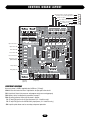
These terminals will provide battery backed power to 24 VDC
devices and are located at the bottom of the electronic control
board at J4 terminals 1 and 2. Terminal 1 is 24 VDC (+) and
number 2 is 0 VDC (-). Peripheral CLASS 2 low voltage devices
that require 24 VDC power maybe connected here (500 ma.
maximum). EXAMPLE: Vehicle detector, radio receiver.
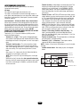
RELAY OUTPUT K1: For class 1 and 2 installations, do not
disconnect siren. S1-6 must be on and S1-8 must be off.
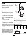
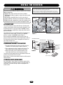
FIGURE 1
Black Lead
–
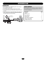
BATTERY INSTALLATION
+
12 VDC Battery 7-10 amp
HOOKING UP BATTERY LEADS: Always hookup and turn on AC
power before installing batteries. After turning on AC power,
install two NEW, fully charged 12 volt DC batteries on shelf next
to motor. Connect red lead from operator to the positive (RED +)
terminal of one battery and black lead from the operator to the
(BLACK-) terminal of the OTHER battery. Place a jumper between
the remaining terminals of each battery if one is not already in
place (Figure 1).
Jumper
–
Red Lead
+
12 VDC Battery 7-10 amp
Failure to install batteries correctly will cause damage and will
not be covered by warranty.
MASTER/SECOND WIRING
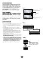
FIGURE 2
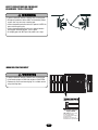
Master/second wire hook up:
1. In a master/second configuration, either unit can be the master.
Choose one unit to be the master and then direct all control
wiring to it (also install vehicle detectors and radio receivers
this unit)
2. At the MASTER, any input (at J5) with control (detectors,
receivers, keypads, timers, etc.) wires to it must also be run to
the same terminals of the second.
Along with these control wires, both operators MUST share a
common ground connection from chassis to chassis (or from
PCB common to PCB common (Ex: master gate J5 terminal
#12 to second gate J5 terminal #12)
EXAMPLE: If only open and close are used at master then three
wires will run between gates (Figure 2). More may be needed
for additional functions to be used.
3. If it is required that if one gate senses an obstruction, the other
reverses also, then 3 additional wires must be run between the
master J3 and second J3 (Figure 3). These connections are for
transmitting IRD (obstruction signals) between both units. This
will allow the master or second to inform the other that a
closing obstruction has occurred and for it to reverse and
open. SET switches on S2, 1-8 the same on both gates.
Master-J5
1
2
3
4
5
6
7
8
9 10 11 12
Common
Close
Open
1
2
3
4
5
6
7
8
9 10 11 12
Second-J5
FIGURE 3
RX GND
1
2
3
TX
4
Master-J3
IRD - Obstruction Signal Connections
Terminal 1 of Master must go to terminal 4
of Second and terminal 1 of Second must
go to terminal 4 of Master. Terminal 2 of
Master must go to terminal 2 of Second.
Second-J3
1
2
3
RX GND
12
4
TX