1
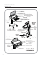
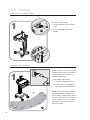
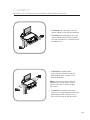
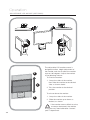
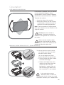
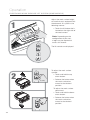
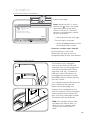
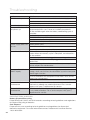
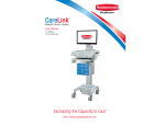
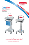
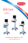
User Manual
Increasing the Capacity to Care™
www.rubbermaidhealthcare.com
Warnings
IMPORTANT – Indicates a situation that does not present any hazard but is
very important in maintaining a well functioning workstation.
ATTENTION – Consult manual to avoid a potentially
hazardous situation which may result in minor or
moderate injury.
ELECTRICAL – Indicates an impending electrical hazard
which, if not avoided, may result in personal injury, fire and/or death.
• The supplied power cord is rated for medical use. Connecting the cord to an outlet that
is not medical grade (indicated with a green dot) will not ensure grounding protection.
• Power cord, USB extension, and workstation are for INDOOR use only. DO NOT
OPERATE OUTDOORS.
• Keep power cord away from water. DO NOT PLUG CORD INTO OUTLET IF WET.
• DO NOT OPERATE PRODUCT IF WET. If the WORKSTATION becomes wet, unplug it
immediately, wipe off any excess liquid, and allow it to dry before using again.
• Inspect power cord before integration. DO NOT USE POWER CORD IF DAMAGED.
• Fully insert power cord plug into outlet. DO NOT unplug by pulling on cord. DO NOT
remove, bend or modify any metal prongs or pins of power cord.
• DO NOT use excessive force to make mechanical or electrical connections.
• DO NOT obstruct the cooling vents.
• DO NOT use an electrical extension cord with your workstation.
• DO NOT operate the lift system when there is an obstruction.
• DO NOT use a flammable cleaner on the station as it can result in fire or explosion.
• DO NOT overload the cart. Weight of technology components and monitor not to
exceed 30 pounds (13.6 kg). Weight of monitor not to exceed 15 lbs. (6.8 kg).
• DO NOT operate the cart on an incline exceeding 10 degrees.
• DO NOT use the cart to power equipment that is not part of the configured cart
system. The cart power system is designed to only power components that have been
integrated with the CareLink cart.
To avoid potential electrical shock, DO NOT simultaneously touch any
component of the CareLink cart system and the patient or any apparatus not
connected to the CareLink system. Electric current may try to flow through you between
the CareLink system and the point of contact as it seeks the easiest path to ground.
1
Table of Contents
Warnings
1
Introduction
3
Overall View......................................................................3
Specifications ...................................................................4
Statement of Use..............................................................4
Get Started
5
Plug in the Power Cord ....................................................5
Charge the Battery ...........................................................5
Operation
6
Quick Start Procedure ......................................................6
Power the CareLink Cart ..................................................7
The Battery Charge Indicator ............................................8
Use the TouchScreen .......................................................9
TouchScreen Log In/Log out.............................................10
The Casters ......................................................................12
N-Stride (some models) ....................................................12
Extend the Keyboard, Mousepad, and Work Surface........13
Adjustable LCD Mount (optional) ......................................15
Manual Work Surface Lift (some models) ........................16
Electronic Work Surface Lift System (some models)..........17
Task Lighting ...................................................................19
Settings (standard)/Preferences (optional) .........................21
Calculator (optional) ..........................................................22
Service Request (optional) ................................................23
Notifications (optional).......................................................25
External Usb Ports............................................................26
Help Screen......................................................................27
Maintenance
28
Cleaning ...........................................................................28
Troubleshooting
29
Cart/Battery Disposal .......................................................29
Service
30
Service Request ...............................................................30
Service Level Commitment ...............................................30
Warranty
30
Limited Warranty for CareLink Computer Cart...................30
Service Details ..................................................................30
Standards Compliance
31
Transport/Storage.............................................................31
2
Introduction
OVERALL VIEW
Monitor
( Customer Provided )
Work Surface Light
( some models )
Work Surface
Manual Height Handle
( some models )
Keyboard
( customer provided )
Keyboard Tray
Bi-directional
Extended
Work Surface
Mousepad
( customer provided )
Adjustable
Monitor
Mount
(optional)
Rear
Handle
LCD Cart
Configuration
Power
Cord
Storage Bin
Ground Lights
( some models )
Cord Holder
Locking
Caster
Screen Clamp
Power
Inlet
Non-Locking
Caster
Laptop
( customer provided )
Document Cover
Manual Height Handle
( Some Models )
Power Button
Touch Screen
Keyboard Light
N-Stride
Trigger
( some models )
Mouse
( customer provided )
Mouse Holder
3
Laptop Cart
Configuration
Introduction
SPECIFICATIONS
Base Size
17” x 19” (43.2 cm x 48.3 cm)
Weight
Configurations starting at 106 lb (48 kg)
Height Adjustment
15.7” (40 cm)
Cart Height
49.3" to 65" (125.2 cm to 165.3 cm)
Keyboard Height
4.8" (12.2 cm) of vertical travel.
Front of Monitor to Wrist
Rest
Work Surface
22" (55.9 cm)
20.75” w x 10” d (52.7 cm w x 25.4 cm)
Casters
5" (12.7 cm) 2 Locking
Keyboard Platform
Accommodates 1.75” H x 18" W x 8” D (4.5 cm x 45.7
cm x 20.3 cm) USB keyboard
21.5" x 11.1“ x 2.9" (54.6 cm x 28.3 cm x 7.5 cm)
CPU Cavity
LCD Monitor Mount
15 lbs (6.8 kg) max. 24" Monitor Max.
Power Cord
Power Strip/Inverter
2.5 ft (.75 m ) hospital grade spiral cord– extends to 8 ft
(2.4 m), recharges on board technology, 120/240VAC,
6.3A, 50/60Hz.
• 3 - NEMA 5/15 outlets/ 150W output each inverter
UPS input
• Cart has provisions for up to 2 inverters/power strips for
a total of 6 outlets/300W total output.
500 W (fused IEC Inlet)
UPS output
24 Vdc
Sealed Lead Acid (SLA)
Battery
Lithium Battery
U1-24Vdc 480 Wh
U1-24Vdc 512 Wh
STATEMENT OF USE
The CareLink Mobile Nurse Station is designed and manufactured by Rubbermaid
Healthcare. Rubbermaid Healthcare is dedicated to providing innovative quality products.
Our goal is to increase the capacity to care by improving productivity, ergonomics, and
compliance while enhancing your facility image.
• The CareLink Mobile Nurse Station is a mobile computing workstation cart designed
for safe use in general patient areas for the purpose of clinical data entry and retrieval.
• The CareLink mobile computing cart is not intended for home use.
• The CareLink mobile computing cart operates from both AC and DC (rechargeable
battery) power sources.
• The CareLink mobile computing cart has no potential electromagnetic or other
interference risks when operated according to guidelines covered in this instruction
manual.
4
Get Started
PLUG IN THE POWER CORD
1
Install the power cord.
1. Plug the power cord into the
Cart.
2. Place the plug in the cord
holder.
1
2
CHARGE THE BATTERY
When a cart is new, or has been
removed from service for more
than 30 days, the battery will
need conditioning.
1
To condition the battery:
1
1. Plug in the power cord.
2. Leave the cart plugged in
for approximately 8 hours.
Note: The initial touch screen
charge indicator reading may
be incorrect. Charge the cart for
8 hours to ensure that battery is
at full charge, and that charge
indicator is set to the correct
level of charge.
2
5
Operation
QUICK START PROCEDURE
Good practice for starting the CareLink cart is as follows:
1. Turn on the cart (see "Power the CareLink Cart" p8).
2. Note the condition of the battery (the cart may need to be
plugged in).
3. Log In to the touch screen (see "Touchscreen Log In/Log Out"
p11).
4. Move the cart to the desired location.
• Unplug the cart from the wall outlet.
• Place the plug in the cord holder.
• Unlock the casters (see "Casters" p13).
• Move the cart.
5. Lock the casters.
6. Adjust the work surface height. (see "Lift System" p17-19).
7. Set work lights as you need them. (see "Task Lighting" p20-21)
8. When you finish your work cycle, log out from the touch screen.
Note: Plug the cart into an electrical outlet when it will be left
unattended for any length of time.
To fully shut down the cart for service or cleaning you must:
1. Unplug the power cord.
2. On the Help screen, touch the Shutdown button to power
down the cart and internally disconnect the battery.
If the power cord is plugged in after the shutdown button is
pressed, the battery will remain connected to the electrical system.
To power up the cart after shutdown, you must plug in the power
cord to reconnect the battery to the cart electrical system.
Observe local safety procedure to ensure that cart remains
de-energized during maintenance and cleaning cycles.
6
Operation
POWER THE CARELINK CART
Power On
Blue
The Power button is located to the
left of the touch screen. A color band
on the button indicates the power
state of the cart. The power state
band colors are as follows:
• Blue– Power On
The touch screen is enabled, the
cart is functioning normally.
Battery
Recovery Mode
Orange
Power Off
Dark
Note: If the touch screen is
dimmed (sleep mode), touch the
screen to awaken it.
• Orange– Battery Recovery Mode
• The screen is dark.
• The cart and power switch will
not function until the battery is
sufficiently charged.
• Dark– Power Off
• The cart is not functioning.
• The power button will function
to turn the cart on.
Note: The battery recovery mode
is discussed in the Battery
Indicator section of this
manual.
To power the CareLink cart:
• Press and hold down the power
button that is located at left of the
touch screen. (about 2 seconds)
Note: The cart main power button
toggles on and off.
• If the cart is off, hold down the
power button to turn the power on.
• If the cart is on, hold down the
power button, and wait for the cart
to turn off.
Note: If the cart will not power on,
plug the cart into the wall, then try
to power the cart again.
The power button does not disconnect
the battery from the electrical system.
The electrical system is energized.
Use the Shutdown button to de-energize
the cart.
7
Operation
THE BATTERY CHARGE INDICATOR
The battery charge indicator is located
at the center of the touch screen.
The indicator displays both a numeric
listing and graphic representation of the
remaining battery charge.
Refer to the Help screen for more
information,
M
34A
25/
12/
ICU
t9
Car
11
Lift
12:
In
Log User
New
e
9 Tim e
1:4
arg
To Ch
75%
g
Lightin
e
9 Tim g
9:3
inin
Rema
When the graphic indicator is blue:
0:00 Time
To Charge
• The cart is ready for mobile battery
power use.
100%
• Plug in the CareLink when the cart
will be left unattended.
12:00 Time
Remaining
When the graphic indicator is yellow:
25/
12/
ICU
t9
Car
11
M
34A
12:
Lift
In
Log User
New
e
9 Tim e
1:4
arg
To Ch
• The cart may be used on battery
power. There is no immediate need
to plug in the cart.
75%
g
Lightin
e
9 Tim g
9:3
inin
Rema
0:15 Time
To Charge
78%
• The cart does need to be plugged
in to top up the charge before the
charge level drops to the red level.
9:21 Time
Remaining
When the graphic indicator is red:
• If the cart is not plugged in, it must
be plugged in very soon.
25/
12/
ICU
t9
Car
11
M
34A
12:
Lift
In
Log User
New
e
9 Tim e
1:4
arg
To Ch
75%
ng
Lighti
e
9 Tim g
9:3
inin
Rema
When the graphic indicator is clear, the
cart reads 0% charge.
• The cart must be plugged in
immediately to avoid a recovery
period.
• The cart will soon shutdown for
a battery recovery period. Your
computer will not be available to
you during this time.
1:00 Time
To Charge
18%
2:09 Time
Remaining
8
Operation
USE THE TOUCHSCREEN
M
Lift
34A
25/
12/
ICU
9
Cart
11
The touchscreen uses sensitive optical
technology to register touch. A touch
will register just before a finger actually
touches the screen surface. Lightly
contacting the screen will register a
touch.
12:
In
Log User
New
e
9 Tim e
1:4
arg
To Ch
75%
ng
Lighti
e
9 Tim ng
9:3
ini
Rema
Keep the screen clean from
foreign objects to achieve the best
touch sensitivity. Avoid excessive dust
accumulation on all sides of the border of
the screen. See “Cleaning section of this
manual.
Selecting items on the touchscreen
Logout
ICU Cart 9
To select items on your touch screen,
you can:
12/25/11 12:34AM
Add Optional Comment
<Select Request Type>
Send
• Touch once much like a single mouse
click.
Service Request History
Created
Type
Cart
Status
12/29/11
Date Rec’d
Facilities
M48MCT001
Created
12/29/11
IT - Cart
M48MCT001
Created
Cancel
12/29/11
IT - Cart
M48MCT001
Received
12/29/11
12/29/11
Page
1 of 1
• Open a roll down menu as you would
with a right mouse click by:
1. Touch and hold the screen selection
until the roll down menu appears.
2. Then touch the desired menu item.
1
Logout
Return to a Previous Screen
ICU Cart 9
Add Optiona
Optional
tiona
al Comment
a
C
Com
om
<Select Request Type>
<Select Request Type>
N/A
Created
Type
IT - Computer
2
Send
Service
ce Request
ce
R
Reque
equ
qu
que
ue
ue
uest
est History
es
Hiis
Cart
Status
Sta
Stat
Date Rec’d
12/29/11
Facilities
M48MCT001
Created
IT - Cart
M48MCT001
Created
Cancel
IT - Cart
Housekeeping
12/29/11
M48MCT001
Received
12/29/11
12/29/11
IT - Battery
12/29/11
IT - Cart
Facilities
Biomed
Dietary
9
Page
1 of 1
To return to the previous screen, touch
the return button
that is displayed in
the right hand corner of the display.
Operation
TOUCHSCREEN LOG IN/LOG OUT
1
To log in to the touchscreen:
25/
12/
ICU
t9
Car
11
• Touch the Log In New User
button to access the keypad.
M
34A
12:
In
Log User
New
e
9 Tim e
1:4
arg
To Ch
75%
e
9 Tim g
9:3
inin
Rema
Log In
New User
• Enter your PIN. When you type the
correct number of digits:
2
M
34A
11
12:
25/
12/
r PIN
Ente
• The touchscreen will validate
the PIN entered
ICU
t9
Car
e
9 Tim e
1:4
arg
To Ch
3
2
1
6
5
4
9
8
7
0
ar
Cle
g
inin
Rema
• If valid, the touchscreen will
load your personal settings and
activate advanced operation of
the touchscreen.
Enter PIN
1
2
3
4
5
6
7
8
9
Clear
0
• If not valid, the touchscreen will
display an error message and
request entry of a valid PIN.
3
The CareLink cart is ready for use.
M
Lift
34A
25/
12/
ICU
9
Cart
11
12:
In
Log User
New
e
9 Tim e
1:4
arg
To Ch
75%
ng
Lighti
e
9 Tim ng
9:3
ini
Rema
Log Out
To log out from the cart:
• Touch the Logout button
.
10
Operation
THIS PAGE HAS BEEN PURPOSELY LEFT BLANK
11
Operation
THE CASTERS
To operate the casters:
• Lower the tab to lock a caster.
• Lift the tab to unlock a caster.
N-STRIDE (SOME MODELS)
N-Stride is designed to aid straight
line movement of a loaded cart
by locking the right front caster in
position.
To activate N-Stride:
12/
ICU
Cart
9
Logout
• Squeeze the trigger that is
located beneath the left handle.
The N-Stride screen is displayed for
a few seconds when the wheel has
locked in position.
Logout
ICU Cart 9
12/25/11 12:34AM
is displayed
The N-Stride icon
on the right side of the title bar while
the N-Stride is active.
To cancel N-Stride:
• Squeeze the trigger again.
(N-stride toggles on or off with
each squeeze of the trigger)
2
12
Operation
EXTEND THE KEYBOARD, MOUSEPAD, AND WORK SURFACE
The CareLink cart features a retractable
keyboard tray, mousepad, and optional
bidirectional work surface. The retractable
surfaces shrink the overall size of the
cart to allow passage through confined
spaces.
• To Extend the keyboard tray, pull
forward on the keyboard tray.
• To Retract the keyboard tray, push the
front edge of the keyboard tray until
fully retracted.
• To lower the keyboard tray:
1. Tilt up the front of the keyboard tray
to unlock the mechanism.
1
The keyboard tray mount allows the user
to raise and lower the keyboard tray in
relation to the work surface. The user may
also tilt the keyboard tray to type while
standing.
2
2. Push the keyboard tray downward to
the desired position.
• To raise the keyboard tray, Pull the
keyboard tray upward.
• To tilt the keyboard tray, rotate the
knob located at the center of the
keyboard tray mount until the keyboard
tray is tilted as desired.
13
Operation
EXTEND THE KEYBOARD, MOUSEPAD, AND WORK SURFACE
• To Extend the mousepad, pull the
mouse holder in the desired direction.
• To Retract the mousepad, push the
mouse holder toward the keyboard
until the mousepad is centered to the
keyboard tray.
• To Extend the bidirectional
work surface, pull the end of the
bidirectional work surface in the
desired direction.
Note: You may have to push the
opposite end of the work surface
into the Tech box in order to get a
hand hold.
• To Retract the bidirectional work
surface, push the exposed end of the
bidirectional work surface until it is
flush with the side of the tech box.
14
Operation
ADJUSTABLE LCD MOUNT (OPTIONAL)
1
1
2
2
The adjustable LCD monitor mount is
designed to allow height adjustment of
the monitor, and also to allow the monitor
to pivot 180 degrees. Adjust the monitor
in the following manner:
2
To Pivot the monitor:
1
1. Grasp the sides of the monitor,
then slide the monitor to the desired
side, as shown above.
2. Twist the monitor to the desired
position.
To raise or lower the monitor:
2
1. Grasp the sides of the monitor.
2. Slide the monitor up or down as
desired, as shown.
If the monitor seems difficult to raise,
or creeps downward, the monitor
lift system may need calibration. Contact
your IT department.
15
Operation
LCD MONITOR ROTATION
If the feature is enabled, the LCD monitor
may be rotated 90 degrees. Some
configurations will only rotate 90 degrees
clockwise or counter clockwise, not both.
To rotate the monitor:
• Grasp the sides of the monitor.
• Rotate the monitor until the monitor
is positioned as desired (usually full
portrait or full landscape position).
Note: That the monitor will slightly rotate
then stop, indicates that the monitor is not
setup for rotation.
Do Not force the monitor to
rotate. Forcing the monitor to
rotate can damage both the monitor and
the mount.
Make sure the monitor cables
do not wind around the monitor
mount. Always reverse the rotation of the
monitor to keep the cables free.
MANUAL WORK SURFACE LIFT (SOME MODELS)
To raise or lower the work surface:
1
1a. Position your hands to hold
the work surface steady,
1b. Lift the height lever that is
located beneath the right handle.
2. Raise or lower the work surface
to the desired height.
3. Release the height lever, then
slightly raise or lower the work
surface to make sure the
locking pin is seated. (You will
feel the locking pin detent and
lock in position if is not seated.)
2
3
If the worksurface seems
difficult to raise, or seems to
fall too easily, the lift system may need
calibration. Contact your IT department.
16
Operation
ELECTRONIC WORK SURFACE LIFT SYSTEM (SOME MODELS)
Adjust the work surface height
of CareLink carts equipped with
the electronic lift system in the
following manner:
1
/11
• Touch the lift button that is
located on the right side of
the touchscreen.
Lift
AM
12:34
12/25
ICU
9
Cart
In
Log User
New
e
9 Tim e
1:4
arg
To Ch
75%
ng
Lighti
e
9 Tim ng
9:3
ini
Rema
Lift
Note: Depending on the
configuration of your cart,
a login may be required to
access this feature.
The lift controls are displayed.
Presets
Lift
2
To adjust the work surface
upward:
• Touch and hold the up
arrow button.
Presets
• Release the button when
the work surface has
moved to the desired
position.
To adjust the work surface
downward:
• Touch and hold the down
arrow button.
Lift
Presets
17
• Release the button when
the work surface has
moved to the desired
position.
Operation
ELECTRONIC WORK SURFACE LIFT HEIGHT PRESETS (OPTIONAL)
Lift
Electronic lift height presets are
available to users who are logged in.
Individual users may set sitting and
standing height presets to adjust
the CareLink cart for their personal
comfort.
1
Presets
To set height presets:
1. Use the arrow keys to adjust the
work surface to the desired height.
Lift
2
Presets
Lift
25/
12/
ICU
9
Cart
11
M
34A
12:
In
Log User
New
e
9 Tim e
1:4
arg
To Ch
sets
Pre
75%
ng
Lighti
e
9 Tim ng
9:3
ini
Rema
Lift
2. Touch and hold the preset button
for approximately 5 sec. to store
the preset position in memory.
Note: Your saved work surface
Presets
height presets are stored in your
user profile. Your saved presets
will follow you to any cart that
you log in to.
Presets
Move the work surface to your height
presets in the following manner:
• Touch the Standing Button to
move the work surface to the
preset standing height.
• Touch the Sitting Button to move
the work surface to the preset
sitting height.
Presets
Touch the Stop button
that
is displayed on the touchscreen to
stop travel of the work surface before it
reaches a height preset.
18
Operation
TASK LIGHTING
Task lighting is included to enhance cart usability
in darkened patient areas. All CareLink carts
are equipped with a standard keyboard light
operated by using the Lighting button located at
the left side of the touch screen.
1:49 Time
To Charge
75%
Lighting
Optional task lighting configurations can include
a work surface light and ground lights. Optional
lighting configurations are operated from a
lighting menu that is accessed by touching the
Lighting button.
9:39 Time
Remaining
To use the standard configuration keyboard
light:
25/
12/
ICU
11
M
34A
12:
Lift
In
Log User
New
e
9 Tim e
1:4
arg
To Ch
t9
Car
75%
• Touch the Lighting button that is located
on the left side of the touch screen to turn
on the keyboard light.
g
Lightin
e
9 Tim g
9:3
inin
Rema
• Touch the Lighting button again to turn
off the keyboard light.
5/11
12/2
ICU
t9
Car
4AM
12:3
Lift
In
Log User
New
e
9 Tim rge
1:4
To Cha
To access the optional task light buttons:
75%
g
Lightin
e
9 Tim g
9:3
inin
Rema
• Touch the lighting button that is located on
the left side of the touch screen.
Lift
Lighting
The optional task light buttons are displayed.
All On
Surface
Work
Surface
Presets
Keyboard
Ground
Lighting
All On
Keyboard
Work
Surface
Keyboard
Ground
Ground
The optional task light buttons include an
indicator that darkens when button is toggled
on and is gray when the button is toggled off.
• Touch a button to turn on a task light—
the indicator will darken.
• Touch a button with a darkened indicator
to turn off that light— the indicator will
turn gray.
19
Lighting
All On
Work
Surface
Surface
Keyboard
Keyboard
Ground
Ground
Operation
TASK LIGHTING (CONTINUED)
The function of the optional task light buttons is
further explained in the sections that follow:
• The Keyboard button controls the lights
that are located below the touch screen.
• The keyboard light is designed to illuminate
the keyboard area. When the keyboard
tray is retracted, the keyboard light will
illuminate the floor in front of the cart.
Surface
Keyboard
• The Ground button controls lights that are
built into the bottom rear corners of the
technology tray.
Keyboard
The ground lights illuminate the floor at the
rear of the cart to aid navigation of darkened
patient areas.
Ground
• The Work Surface button controls the light
located beneath the LCD monitor (laptop
models do not include a work surface light).
• The work surface light illuminates the
work surface area and the inside of the
technology tray when the work surface is
removed.
Work
Surface
g
g
• The All On/All Off button is used to
operate all task lights simultaneously.
All On
Work
20
Operation
SETTINGS (STANDARD)/PREFERENCES (OPTIONAL)
Logout
ICU Cart 9
12/25/11 12:34AM
1:49 Time
To Charge
Lighting
75%
Log In
New User
Lift
9:39 Time
Remaining
A user who is not logged in may use the
Settings screen to temporarily adjust the
level of touchscreen brightness and alarm
volume.
The cog button
located at the bottom
left of the touchscreen is used to access
both the Settings and Preferences
screens. If no user is logged in, the cog
button will access the Settings screen.
When a user is logged in, the cog button
will access the Preferences screen.
ICU Cart 9
12/25/11 12:34AM
Settings
To change touchscreen settings:
1. Touch the cog button
the Settings screen.
, to access
Display
Brightness
Volume
Control
5
8
2. Change the desired setting:
• Touch the up arrow button to
increment the setting value.
• Touch the down arrow to decrement
the setting value.
4. Touch the return button
to the previous screen.
to return
The Preferences screen allows a logged
in user to adjust the levels of touchscreen
brightness, alarm volume and Log in Time.
To set individual touchscreen Preferences:
1. Log in to the touchscreen if you have
not already done so.
Logout
ICU Cart 9
2. Touch the cog button
Preferences screen.
12/25/11 12:34AM
Preferences
Display
Brightness
Alarm
Volume
Login
Timeout
Drawer Lock
Timeout
3. Change the desired setting:
Minutes
Minutes
Max Value:
12 hours
to access the
Max Value:
10 Minutes
• Touch the up arrow button to increment
the setting value.
Save
• Touch the down arrow to decrement the
setting value.
4. Touch the Save button to save the new
settings to memory and return to the
previous screen
Note: When saved, your preferences will
follow you to any cart that you log in to.
21
Operation
CALCULATOR (OPTIONAL)
To access the CareLink calculator
feature:
• Touch the Calculator button
Logout
ICU Cart 9
Lighting
Lift
75%
1
2
4
5
6
Keyboard
7
8
9
Clear
0
All On
The function of the calculator is
described in the sections that follow:
Enter PIN - Drawers Locked
Work
Surface
9:39 Time
Remaining
Ground
.
12/25/11 12:34AM
1:49 Time
To Charge
3
Presets
123+
456+
123456=0
The Readout
the result.
0
—
9
,
.
: shows each entry and
+/-
,
keys: Enter
numerals on the display. For decimal
places use the . key in the logical
sequence.
g
+/-
key to change the sign of
Use the
the bottom number on the readout.
Logout
ICU Cart 9
12/25/11 12:34AM
M+
7
8
9
M-
4
5
6
CE
/
+
MR
1
2
3
MC
0
+/-
.
x
=
, - ,
,
Function Keys:
Perform the four basic mathematic
calculations when these keys are
Touched in arithmetic sequence with the
number keys.
x
+
Calculator
M
_
123+
456+
123456=0
/
Touch the = key to obtain the answer
after entering numeral and function keys.
M
Memory Icon:
The memory icon is displayed whenever there is a value stored in memory. The icon is
turned off when the memory is clear.
M+
( )
MMemory plus (minus) key:
Transfers the bottom number on the readout to the memory as a positive (negative) value
and automatically adds that value to any value previously stored in the memory.
MR
Memory Recall key:
Recalls the contents of the memory to the bottom line of any number stack shown on
the readout.
MC
Memory Clear key:
Clears the contents of the memory and changes the value to zero.
Back Space key:
Moves the entry cursor back one space and erases the last keyTouch.
CE
Clear Entry key:
Removes the last line of the readout. Touching the
ends processing of any calculations.
CE
key twice clears the readout and
22
Operation
SERVICE REQUEST (OPTIONAL)
Logout
ICU Cart 9
12/25/11 12:34AM
Lift
1:49 Time
To Charge
Lighting
Enter PIN - Drawers Locked
75%
All On
Work
Surface
Keyboard
9:39 Time
Remaining
Ground
1
2
3
4
5
6
7
8
9
Clear
0
Presets
The Service Request
button is
used to send requests from the cart.
A new request may be canceled until
it is acknowledged. Once a request
has been acknowledged, the Cancel
button is replaced with the date
received.
Note: Do Not use the Service
Request system to transmit patient
or HIPAA protected Information.
Logout
ICU Cart 9
12/25/11 12:34AM
Add Optional Comment
<Select Request Type>
Send
Service Request History
Created
Type
Cart
Status
12/29/11
12/29/11
12/29/11
Date Rec’d
Facilities
M48MCT001
Created
IT - Cart
M48MCT001
Created
Cancel
IT - Cart
M48MCT001
Received
12/29/11
12/29/11
Page
1 of 1
The Service Request screen displays
a listing of requests sent from the cart.
To access the Service Request
screen:
• Touch the Service Request
button.
A pending request may be canceled
and removed as long as the Cancel
button is visible.
To cancel a pending request:
• Touch the Cancel button to
delete the request from the
system.
23
Operation
SERVICE REQUEST (OPTIONAL)
1
Logout
ICU Cart 9
12/25/11
Add O
<Select Request Type>
Service Req
Logout
ICU Cart 9
12/25/11 12:34AM
Created
<Select Request Type>
N/A
Created
Type
IT - Computer
Type
Add Optional Comment
<Select Request Type>
Cart
Send
To send a request from the cart:
Service Request History
Cart
Status
Facilities
M48MCT001
Created
IT - Cart
M48MCT001
Created
Cancel
IT - Cart
Housekeeping
12/29/11
M48MCT001
Received
12/29/11
12/29/11
Date Rec’d
12/29/11
IT - Battery
12/29/11
IT - Cart
2
Page
1 of 1
Note: Make sure the Wi-Fi is
Facilities
active. Look for the
Icon in
the upper right hand corner of the
touch screen. If Wi-Fi is not active
requests and notifications cannot
be sent or received.
Biomed
Dietary
1. Touch the Select Request Type
window to roll down the Request
Type menu.
2. Touch the desired message type.
3
12/25/11 12:34AM
Add Optional Comment
Send
Service Request History
Logout
Cart
12/25/11
12:34AM
ICU Cart 9
Status
Date Rec’d
4
12/29/11
<Select Request Type>
1
2
Q
W
A
3
Add Optional Comment
4
5
6
R
T
Y
F
G
7
8
9
0
I
O
P
K
L
Enter
Z
V
3a
-
.
3b
3. If it is necessary to add
additional information, Touch
the Additional Comments
window to display the on-screen
keyboard.
3a. Type in your comment.
3b. When finished, touch the Enter
key.
4. Touch the Send button to
send the message to the
management system.
The new message will appear at the
top of the message list.
24
Operation
NOTIFICATIONS (OPTIONAL)
Logout
ICU Cart 9
(1)
Type
12/25/11 12:34AM
Notifications
(1)
To
Subject
Date
Jane Doe
Facilities
Tornado Warning
12/29/11 3:54PM
ICU Dept
Lab
From
Results Ready
12/29/11 3:54PM
John Doe
Pharmacy
Maintenance
12/29/11 3:54PM
Jane Doe
Housekeeping
Housekeeping Request
12/29/11 3:54PM
John Doe
Pharmacy
Medications Are Ready
12/29/11 3:54PM
The Notifications button 2
is used
to display a list of messages sent to
a cart user. There are two types of
messages:
Page
3 of 6
pop up to be
• Alerts
read immediately. The icon is
displayed when there are active
alerts on the list.
1
1
• Messages 2 may be read at
the users convenience. The icon
displays the number of active
messages on the list.
1
Logout
ICU Cart 9
(1)
To display the message list:
Type
• Touch the Notifications button
at the bottom of the screen.
2
The Notifications screen is displayed.
12/25/11 12:34AM
Notifications
(1)
To
From
Subject
Date
Jane Doe
Facilities
Tornado Warning
12/29/11 3:54PM
ICU Dept
Lab
Results Ready
12/29/11 3:54PM
John Doe
Pharmacy
Maintenance
12/29/11 3:54PM
Jane Doe
Housekeeping
Housekeeping Request
12/29/11 3:54PM
John Doe
Pharmacy
Medications Are Ready
12/29/11 3:54PM
Page
3 of 6
1
Cart 9
12/25/11 12:34AM
(1)
Notifications
Subject
Date
Doe
Facilities
From
Tornado Warning
12/29/11 3:54PM
ept
Lab
Results Ready
12/29/11 3:54PM
Doe
Pharmacy
Maintenance
12/29/11 3:54PM
Doe
Housekeeping
Housekeeping Request
12/29/11 3:54PM
Doe
Pharmacy
Medications Are Ready
12/29/11 3:54PM
1
25
To scroll through the message list:
Page
3 of 6
Page
3 of 6
• Use the arrow keys to scroll
through the list.
• The inner arrow keys scroll one
message at a time.
• The outer arrow keys scroll one
page at a time
Operation
NOTIFICATIONS (OPTIONAL)
p
Logout
ICU Cart 9
John Doe
Pharmacy
Main
Jane Doe
Housekeeping
Hous
John Doe
Pharmacy
Medi
12/25/11 12:34AM
Dec 28, 2012
From: John Doe-Pharmacy
To: All carts
Prev Next
Subject: Medications Are Ready
Your medication order is ready for pick up.
To read a message:
Note: Make sure Wi-Fi is active.
Look for the
Icon in the upper
right hand corner of the touch
screen. If the Wi-Fi is not active,
requests and notifications cannot
be sent or received.
Close
• Touch the title of the message.
2
The message is displayed
• Touch the Close button to return
to the Notifications screen.
Requests and Messages Deleted
Service Requests, Alerts and
Notifications are kept active for a
configured period of time, then deleted.
EXTERNAL USB PORTS
The CareLink cart is equipped
with up to two external USB port
extensions that may be plugged into
a customer provided USB source
(computer, hub, etc). The external
USB ports allow USB devices to
be plugged into customer installed
technology devices without opening
the work surface.
The standard external USB extension
port is located at the right rear
bottom of the technology tray.
CareLink carts configured for use
with LCD monitors may be equipped
with an optional work surface task
light. The work surface light includes
an external USB port extension.
Note: if an available external USB
port does not seem to work, it is
likely that it has not been setup
for your cart. Contact your IT
dept.
26
Operation
HELP SCREEN
The Help button
is used to display the
help screen. The help screen contains:
1
• A listing of control system screen
buttons and icons.
• The optional Battery Help button.
• The optional Reboot button – used to
reboot the cart computer.
• The Shutdown button – used to
completely shutdown the cart and
disconnect the battery.
The power cord must be unplugged
before using the Shut Down button.
To use the Shut Down button:
1. Touch the Help button.
2. Unplug the Power Cord.
3. Press the Shutdown button.
The cart must be plugged in to power up
the cart after shut down.
To access the help screen —
• Touch the Help button.
To display the definition of a screen icon
or button —
• Touch the icon in the left hand
pane of the help screen.
The definition of that icon is
displayed in the right hand pane.
1
Reboot Computer Button (optional)
To reboot the CareLink Computer:
• Touch the Reboot button as shown.
• A confirmation screen is displayed
• Touch the Yes button to reboot the
computer.
• Touch the No button to cancel the
reboot and return to the help screen.
27
Maintenance
DO NOT use the computer cart if
pieces are missing or the unit is
damaged. In these cases, immediately
contact Rubbermaid Healthcare Customer
Service for more information: 1-888-8598294.
Cables: Always keep the cables neatly
organized and be sure to route cables
away from moving components with wire
ties or cable clips.
Electric Cables: Periodically inspect power
cord and plug to ensure plug is not bent
and cable is not frayed.
CLEANING
CAUTION: Because of the close
proximity of electrical power and
equipment, flammable cleaners should
never be used on the computer cart.
To clean the cart:
1. Turn off the cart.
• Turn off any technology installed, on
the cart.
• Press the cart Power button to shut
down the cart.
2. Disconnect the power cord from the
wall.
• Verify that your computer cart is
unplugged from the wall outlet before
cleaning.
• Allow your computer cart to dry
completely before plugging the power
cord into a wall outlet.
• When cleaning the computer cart,
wipe surface with a damp cloth and
thoroughly dry.
• NEVER cover the computer cart or its
components with liquid or allow liquids
to flow into the computer cart.
• NEVER use steel wool or other abrasive
material as these could damage the
surface finish.
• Before using any cleaner on the
computer cart, first test on a small area
to ensure that the surface is not harmed.
• These guidelines cannot guarantee
infection control. The hospital’s Infection
Control Administrator should be
consulted regarding cleaning procedures
and schedules.
• Clean plastic components with diluted,
non-abrasive solutions. Suggested
cleaners are water, soap, diluted bleach
and alcohol solutions.
• Remove pen and dry erase marker
stains with a soft cloth and 91%
isopropyl alcohol.
• Remove iodine stains with a soft cloth
and any cleaners suggested above.
The touch screen requires periodic
cleaning to remove any particles on the
surface of the screen.
• Use a soft cloth or paper towel
dampened with a typical household glass
cleaner to clean the glass surface of the
touch screen.
• To maintain touch sensitivity, keep the
screen clean from foreign objects.
• Avoid excessive dust accumulation on
all sides and edges of the screen.
To clean the touch screen:
1 Spray a small amount of a mild glass
cleaner onto a soft cloth or paper towel.
2 Wipe the surface of the touch screen
to remove any dirt, fingerprints, or
other debris that could hinder touch
recognition.
DO NOT use the following
chemicals to clean your computer
cart: acetone, mineral spirits, abrasive
cleansers, paint thinner or any other harsh
or toxic chemicals.
28
Troubleshooting
Problem
Solution
Cart Is hard to push.
Check that the caster locks are in the unlocked (up) position.
Check casters for obstructions.
Cart is hard to turn.
Computer/Monitor will
not power up.
Check that N-Stride is active.
Check that cart power button is not orange and battery is
disconnected from cart. Power to installed components
will be available again after the battery conditioning cycle is
complete.
Check that power supply is turned on.
Check that device power cables are connected.
Check that wall outlet has power.
Check fuses at the power inlet.
Power supply does not Check power cord.
turn on.
Check that wall outlet has power.
Cart will not Power Up
Computer Does Not
Work Properly
Check fuses at cabinet power inlet.
If Power Button, is orange indicating battery is in recovery
mode. When the recovery cycle is complete, cart electronics
will be enabled.
Check that power cord is plugged into a working outlet.
Check that end of power cord is plugged into the cart
power inlet.
After completing above checks cart will not power up, file a
service request for maintenance.
Check that power button is not orange. If power button is
orange, when cart finishes the recondition cycle the computer
should again function.
If cart is functional, but computer will not work, file a service
request for maintenance.
Manual Lift Mechanism If it is difficult to raise and lower the work surface, the lift
Performance
mechanism preload may need adjustment. File a service
request with your IT department for service.
Electronic Lift
If the electronic lift is stuck in position or is running slowly,
Performance
it may need calibration. File a service request with your IT
department for service.
CART/BATTERY DISPOSAL
Battery Disposal/Recycling
Dispose/Recycle Lithium and SLA batteries according to local guidelines and regulations
for disposal/recycling of batteries.
Cart Disposal
Dispose of this cart according to local guidelines and regulations for disposal of
electronic equipment. For more information contact Rubbermaid Customer Service:
1-800-859-8292.
29
Service
SERVICE REQUEST
Contact your IT department, or file a service request at our website: www.
rubbermaidmedical.com/service.
SERVICE LEVEL COMMITMENT
Rubbermaid Medical Solutions is committed to providing best-in-class service. This
document details our standard warranty and instructions on how to request service using
our customer support system.
• Rubbermaid Healthcare will provide a service manual upon request.
Warranty
LIMITED WARRANTY FOR CARELINK COMPUTER CART
Rubbermaid Healthcare is pleased to offer a three-year warranty on durable components
and a three-year warranty on electronic components.
If during the warranty period this Rubbermaid Healthcare product proves defective in
materials or workmanship under normal use by the original purchaser, please contact
Rubbermaid Healthcare technical support (please be ready to furnish complete
information, including product serial number, description of the issue, and full contact
information). Rubbermaid Healthcare will determine, at its sole discretion, how to
best address your warranty issue, which may include sending you a replacement part
covered under warranty or for sale. Rubbermaid Healthcare reserves the right to require
proof-of-purchase prior to honoring any warranty request. This warranty does not cover
product abuse, modification, failure to adhere to product instructions, or improper
operation/misuse. RUBBERMAID HEALTHCARE SHALL NOT BE LIABLE FOR ANY
CONSEQUENTIAL OR INCIDENTAL DAMAGES WHATSOEVER. Some states do not
allow the exclusion or limitation of incidental or consequential damages, so the above
limitation or exclusion may not apply to you. This warranty gives you specific legal rights
and you may also have other rights which vary from state to state or country to country.
SERVICE DETAILS
Consumable components are not covered under warranty and include:
• Locks and Keys
• Document Cover
Other standard components will be replaced under the applicable warranty following a
filed service request.
*The above terms for replacement parts applies to facilities located in the United
States. All other customers should contact the appropriate reseller for the terms of part
replacement.
All terms are subject to change without notice.
30
Standards Compliance
Tested to comply with:
• NRTL certified to
o UL 60601-1 - Issued:2003/04/25 Ed:1 Rev: 2006/04/26 UL Standard for Safety
Medical Electrical Equipment, Part 1: General Requirements for Safety
o CSA C22.2 No. 60601-1 - Issue: 2008/02/01 Ed:2 Medical electrical equipment Part 1: General requirements for basic safety and essential performance; COR 2:
2011/06/01
o IEC 60601-1-1 - Issued:2000/12/01 Ed:2 Medical Electrical Equipment - Part 1-1:
General Requirements for Safety - Collateral Standard: Safety Requirements for
Medical Electrical Systems
• IEC/EN 60601-1-2 (Ed. 2): 2001 +A1: 2004 - Medical electrical equipment Part 1-2:
General requirements for safety - Collateral standard: Electromagnetic compatibility
o Conducted Emissions - Conducted Voltages (CISPR 11/ EN 55011 (CV))
o Radiated Emissions - Electric Fields (CISPR 11/ EN 55011 (RE-E))
o Electrostatic Discharge Immunity Test - (IEC 61000-4-2)
o Radiated, radio-frequency, electromagnetic field immunity test (IEC 61000-4-3)
o Electrical Fast Transient/Burst Immunity Test (IEC 61000-4-4)
o Surge Immunity Test (IEC 61000-4-5)
o Immunity to conducted disturbances, induced by radio-frequency fields (IEC
61000-4-6)
o Power Frequency Magnetic Field Immunity Test (IEC 61000-4-8)
o Voltage Dips, Short Interruptions and Voltage Variations Immunity Tests (IEC 610004-11)
Compatibility – Requirements and Tests
• FCC PART 15, Subpart B, Class A – Unintentional Radiators
This product is classified as:
o Class 1/ Internally powered device with no applied parts.
o This equipment is designed for continuous operation.
o Class A, Group 1 ISM Equipment
o This device is classified IPXO for water ingress
o Input 500 Watts North America
TRANSPORT/STORAGE
• The shipping weight of the CareLink cart is approximately 160 lbs (72 kg).
Use proper lifting techniques to prevent injury.
• Care should be taken to transport and store this system within a temperature range of
32ºF to 90ºF (0ºC to 32ºC); Humidity 20% RH to 95% RH non-condensing.
31
REVISION HISTORY
Revision
Date
Description of Changes
A
02/2013
Initial Release
B
05/2013
Compliance Data
32
1-888-859-8294
www.RubbermaidHealthcare.com
05/2013 Part # 1817585 Rev. B CareLink Computer Cart User Manual
© Rubbermaid Healthcare
Huntersville, NC 28078