1
Telemedicine
Wall-Mounted Solution
User Manual
Increasing the Capacity to Care
www.rubbermaidhealthcare.com
TM
2
Table of Contents
Summary of Warnings
4
Box Contents
6
Component Layout
7
Get Started
8
Enclosure Installation
9
Placement Of the Enclosure ............................................................................................ 9
Install the Camera ........................................................................................................... 9
Wall Track ......................................................................................................................10
Rear Mount ...................................................................................................................11
VidyoRoom Configuration
13
Initial Setup of the VidyoPortal ........................................................................................13
Change the VidyoRoom Settings ....................................................................................15
Change the Account Settings ...................................................................................15
Change the Network Settings ...................................................................................16
Change the Proxy Settings .......................................................................................17
Change the Audio Settings .......................................................................................18
Change the Video Settings .......................................................................................18
Change the Language Settings .................................................................................20
Change The My Room Setting ..................................................................................21
Change Other Preferences ........................................................................................21
Viewing the About Information ..................................................................................22
The About page displays version and release information for your model of VidyoRoom.
22
Operation
23
Power On the Wall Mounted Solution .............................................................................23
VidyoRoom Interface Devices .........................................................................................23
The Vidyo Remote Control - Not in Conference
24
The Vidyo Remote Control - In Conference
25
Connect to a Meeting ....................................................................................................26
Integration
29
Install the Teleconferencing and Other Technology Devices
29
Install the Front Cover ....................................................................................................30
Install the Primary Monitor ..............................................................................................31
Install the Camera ..........................................................................................................33
Service And Support
34
Service level commitment ...............................................................................................34
Maintenance And Cleaning
34
Environmental Data
36
Limited Warranty
36
Statement of Use
37
3
Summary of Warnings
The power system is designed for enclosure mounted equipment only. Do not connect
equipment that is not mounted to the enclosure to the power system outlets. Do not connect
enclosure mounted equipment directly into a power source that is not mounted to the
enclosure.
Power cord, power system and enclosure are for INDOOR use only. DO NOT OPERATE
OUTDOORS.
Keep power cord away from water. DO NOT PLUG CORD INTO OUTLET IF WET.
DO NOT OPERATE POWER SYSTEM IF WET. If your enclosure becomes wet, unplug it
immediately, wipe off any excess liquid, and allow it to dry before using again.
EQUIPMENT not suitable for use in the presence of a FLAMMABLE ANAESTHETIC FIXTURE
WITH AIR, or WITH METERED OXYGEN OR NITROUS OXIDE.
Inspect power cord before each use. DO NOT USE CORD IF DAMAGED.
Fully insert power cord plug into outlet. DO NOT unplug by pulling on cord. DO NOT remove,
bend or modify any metal prongs or pins of enclosure power cord.
DO NOT use excessive force to make connections.
DO NOT ALLOW CORD TO OVERHEAT
Only authorized personnel, experienced with servicing electrical equipment should open the
power system.
Do not use an electrical extension cord with the enclosure.
Do not use a flammable cleaner on the wall enclosure as it can result in fire or explosion.
Do not touch or unplug the camera or display power cord while touching the patient
4
Summary of Warnings
Symbol
Signal Word
Level of Hazard
IMPORTANT
Indicates a situation that does not present any
hazard but is very important in maintaining a
well functioning cart.
ATTENTION
Consult accompanying document to avoid
a potentially hazardous situation which
may result in minor or moderate injury.
ELECTRICAL
Indicates an impending electrical hazard
which, if not avoided, may result in personal
injury, fire and/or death.
DISPOSAL
Transport/Storage
Dispose of this enclosure according
to local guidelines and regulations
for waste. Contact Rubbermaid
Care should be taken to transport
and store this system within a
temperature range of 32º F to 90º
F (0º C to 32º C); Pressure 500 hPa
to 1060 hPa; Humidity 20% RH to
95% RH non-condensing
Customer Service for more
information: 1-888-859-8294
5
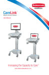
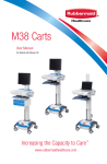
Box Contents
A
A1
B
OR
A2
A3
Fully Integrated Telemedicine Wall
Mounted Solution
Unpopulated Wall Mounted
Telemedicine Enclosure
A1 Video Camera
A4
A2 Speaker/Microphone Array
A3 Speaker Array Ceiling Mount Kit
A4 Audio Cable
C
E
D
Par
t #0
00
00
00
Wa
ll M
oun
ted
Solu
tion
A
Fully Integrated Telemedicine Wall
Mounted Solution
B
Unpopulated Wall Mounted Telemedicine
Enclosure
C
Wall Track
D
Wall Track Mounting Template
E
Wall Track Mounting Hardware
F
Front Monitor Mount Blank
G
Power Cord
H
Network Cable
Drill
Drill
x4 E1
x4 E2
Drill
Drill
x4 E3
Drill
Dri
ll
tSte hole
s
w el stu ize
Drill
it d
t W h anc installa
ood hors tio
with stud and n: 1/2
woo insta screw " for
d sc llati s p use
rew on: 1 rovid s p /8" ed
rovi fo
ded r use
E1 Wood Screw
E2
Machine Screw
E3 Wall Anchor
6
F
G
H
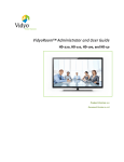
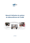
Component Layout
Video
VISCA
Power
Cables
Camera
Adjustable
VESA
Mount
Monitor
Network Connector
External
USB Connector
Telemedicine Wall
Mount Enclosure
Power Indicator
Locking Screws
VESA Mount
Rear Bracket
Power Switch
Fuse Holder
IEC Power
Inlet
Wall Track
7
Get Started
Ready the Telemedicine Wall Mounted Solution for operation as follows:
1. Compare the contents of the shipping carton with the Box Contents section on page 6.
2. If you have not already done so, design and prepare the Telemedicine Event Room.
• See— http://www.vidyo.com/documents/support/v2.2/VidyoRoom_User’s_Guide_2.2.pdf
3. Install the necessary electrical, network, and audio/visual services to support the Telemedicine Wall
Mounted Solution.
4. Install the speaker/microphone array and route the cable to the Wall Mounted Solution.
•
Use the documentation provided with the Speaker Array and Ceiling Mount Kit which is also
available at— http://www.phnxaudio.com/rfv-28.aspx and http://www.phnxaudio.com/rfv16.aspx
5. If necessary, integrate the Telemedicine system. See— page 29
6. If necessary, mount the camera to the telemedicine system. See - page
7. Mount the Wall Track. See— page 10
8. Install the Rear Mount. See—page 11
9. Place the Wall Mounted Solution in the Wall Mount and make the necessary cable connections.
See— page 12
10. Power the Wall Mounted Solution. See— page 23
11. Configure the teleconferencing system.
•
The VideoRoom User Guide is available at— http://www.vidyo.com/documents/support/v2.2/
VidyoRoom_User’s_Guide_2.2.pdf
The Telemedicine Wall Mounted Solution is ready.
Enclosure Installation
PLACEMENT OF THE ENCLOSURE
The Telemedicine Wall Mounted Solution should be located so that the camera can provide good
coverage of the patient or conference area. It may be necessary to install electrical, audio, and USB
service in close proximity to the enclosure mounting area.
8
Enclosure Installation
MOVE THE CAMERA MOUNT
1
The camera may be mounted at the
top or bottom of the enclosure. The
camera mount is moved as shown to
facilitate mounting the camera in the
desired location.
2
To move the camera mount:
• Remove the screw and camera
mount from the original
enclosure location.
4
3
•
Position the camera mount in
the desired location.
•
Install the screw and camera
mount in the new location on
the enclosure.
•
The camera mount is ready.
Enclosure Installation
INSTALL THE CAMERA
•
•
Connect the cables to the camera.
•
Connect the power cable.
•
Connect the VISCA control cable.
•
Connect the video cable.
Use the mounting screw (provided with
the camera) to mount the camera to the
camera bracket as shown.
Note: If a mounting screw is not provided
with the camera, refer to the camera
documentation in order to acquire the
correct size mounting screw.
9
Enclosure Installation
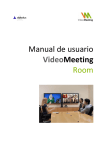
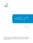
WALL TRACK
NOTE:
1
10
CE ” TO
EX ILING 12”
TR
US TO
ION
{
GROMMET
HOLE
RJ 45 FROM
ELERT
USB A FROM
MT304
DATA LAN
JACK
}½” TO 1”
D
}
}2”
Consult the Engineer of Record regarding
structural codes and utilities.
Use the wall track template (C) to determine
drill hole locations. Align the template with
the floor , at the desired height from the
floor. Mark and drill holes.
TO 3”
½” TO 1½”
o Install wall track (D) using hardware provided.
2
NOTE:
Use part wall anchor (E3) and machine
screws (E2) for steel stud installation. Use
wood screws (E1) for wood studs.
C
10
Enclosure Installation
REAR MOUNT
1
2
Remove the wall mount bracket from the
enclosure mount assembly.
Loosen the 2 T-Nut screws enough to insert the
T-Nut/Wall Mount assembly into the wall Track.
11
Enclosure Installation
REAR MOUNT
•
3
Insert and position the T-Nut/Wall mount
assembly on the Wall Track.
Tighten the 2 T-Nut screws to lock the
wall mount in position.
•
Insert the Telemedicine Wall Mounted Solution
assembly into the wall mount as shown.
4
12
Tighten the locking screws to lock the VESA
mount in position.
Locking
Screw
•
Plug in the power cord.
•
Plug in the network cable.
•
Plug in the USB audio cable.
VidyoRoom Configuration
INITIAL SETUP OF THE VIDYOPORTAL
The first use of the VidyoRoom requires configuration of the portal in order to enable the All In One
Telemedicine Unit. This section describes setting up a new portal.
To begin, power on your VidyoRoom system.
The Account screen will display the default IP address for the VidyoPortal as well as the factory default
user name and password. Change the user name and password as described below.
To enter VidyoPortal IP address, user name, and password:
1. Enter the VidyoPortal IP address or URL. (You don’t have to type the usual “http://”.)
2. Enter the user name and password for the VidyoPortal.
3. Use the arrow buttons on the remote control to navigate to the Save button and then press the OK
button on the remote control.
If you receive any errors, double check your user name, password, server address settings, and network
configuration. For more information about how to change the network settings as well as the other
settings for the VidyoRoom, see the “Changing the VidyoRoom Settings” section of the VidyoRoom User
Guide ( http://www.vidyo.com/documents/support/v2.2/VidyoRoom_User’s_Guide_2.2.pdf ).
13
VidyoRoom Configuration
CHANGE THE VIDYOROOM SETTINGS
2. In the IR Receiver field, select between using an internal IR receiver or an external IR receiver.
3. In the Auto answer field, select On if you want the VidyoRoom to automatically answer incoming calls.
4. In the Join/Exit tones field, select On if you want to hear a tone every time someone joins or leaves the
conference.
5. In the Far end camera control field, you can determine whether or not users can control far-end
cameras. For FECC to work, the cameras must be capable of electronic tilt and pan.
6. If you want to set an access code to prevent unauthorized access to your VidyoRoom configuration
settings, select the Enable settings access code checkbox.
When a user accesses the settings from the VidyoPortal Home page, they must enter this access code to
access the settings. If you select this checkbox, you must enter the access code in the Settings Access
Code field.
7. Arrow to the Save button onscreen and press on the remote control.
8. To restart the VidyoRoom, select the Restart VidyoRoom button.
It will take several seconds for the VidyoRoom to restart.
14
VidyoRoom Configuration
CHANGE THE VIDYOROOM SETTINGS
This chapter describes how to use the Settings Page to maintain and change VidyoRoom
settings. To access the Settings page, arrow to the Settings link on the VidyoPortal Home
page and press the OK button on the remote control.
CHANGE THE ACCOUNT SETTINGS
You must enter the account settings when you first set up your VidyoRoom.
You will also have to enter the account settings if you re-image your VidyoRoom using the
factory restore key (but not if you re-image using the Web Configuration pages or through
the Recovery Console). For information about how to re-image a VidyoRoom, refer to the
VidyoRoom Firmware Upgrade and Recovery Procedure Technical Note.
To change account settings:
1. Select the Account tab on the Settings page.
15
VidyoRoom Configuration
CHANGE THE VIDYOROOM SETTINGS
2. In the Portal field, enter the IP address or fully qualified domain name for your VidyoRoom system.
3. In the User Name field, enter the VidyoRoom username.
4. In the Password field, enter the VidyoRoom password. You must specify a username and password in
order to log into the VidyoRoom.
5. Arrow to the Save button onscreen and press on the remote control.
CHANGE THE NETWORK SETTINGS
To change network settings:
2. Select the Network tab on the Settings page.
Your VidyoRoom is set to Use DHCP by default. This enables it to automatically obtain its IP address.
16
VidyoRoom Configuration
CHANGE THE VIDYOROOM SETTINGS
2. To change your VidyoRoom network settings, select Use static IP address and enter your network’s
settings appropriately:
•
IP Address
•
Subnet Mask
•
Default Gateway
•
Primary DNS Server
3. To define a range of UDP ports for use with the VidyoRoom, enter the appropriate values in the UDP
Start and UDP End fields.
4. Arrow to the Save button onscreen and press on the remote control.
CHANGE THE PROXY SETTINGS
A VidyoProxy routes all data signals through a single port in order to traverse a firewall.
To change proxy settings:
1. Select the Proxy tab on the Settings page.
2. If you are using a VidyoProxy, select Use VidyoProxy.
3. Arrow to the Save button onscreen and press on the remote control.
17
VidyoRoom Configuration
CHANGE THE VIDYOROOM SETTINGS
CHANGE THE AUDIO SETTINGS
To change audio settings:
1. Select the Audio tab on the Settings page.
The audio settings for the various VidyoRoom models may vary slightly. The following illustration shows
the Audio tab for the HD-220.
2. For most speakerphone systems, set both the microphone and speaker volumes to about 60% to
start.
You can adjust the volume for each one separately.
3. Arrow to the Save button onscreen and press on the remote control.
CHANGE THE VIDEO SETTINGS
To change video settings:
1. Select the Video tab on the Settings page.
18
VidyoRoom Configuration
CHANGE THE VIDYOROOM SETTINGS
2. In the Displays field, select the number of displays.
Note: Dual display mode for the HD-100 is only for data sharing. The HD-100 supports 1024 x 768 (XGA)
resolution for the data display.
3. In the Display Resolution field, select 720p or 1080p.
4. In the Max Tx Bandwidth field, select one of the maximum transmit bandwidth options.
5. In the Transmit Resolution field, select one of the transmit resolution options.
19
VidyoRoom Configuration
CHANGE THE VIDYOROOM SETTINGS
These options differ based on the VidyoRoom model. For example, the HD-220 and HD-100 have a
1080p15 option, but the HD-50 does not. See page 57 for a list of the resolutions available for each
VidyoRoom model.
6. If the Camera Control field is present for your VidyoRoom model, you can reset the camera or
compensate for backlighting.
7. Arrow to the Save button onscreen and press on the remote control.
Note: An Administrator can set transmit and receive bandwidth limits for all users of any Group. This
Group policy generally prevails. When a user is in a conference that includes a VidyoRoom, however, the
VidyoRoom’s transmit bandwidth will override the Group policy.
For example, let’s say a Group policy is set at a maximum transmit and receive bandwidth of 1 Mbps for
all members of the Group. The VidyoRoom, however, can transmit at 2 Mbps. Those participants whose
Internet connections and computers can handle the higher bandwidth will receive 2 Mbps from the
VidyoRoom.
CHANGE THE LANGUAGE SETTINGS
To change language settings:
1. Select the Language tab on the Settings page.
The VidyoRoom is available in these 14 languages:
•
•
•
•
•
English
Finnish
Italian
Thai
Spanish
2. Select your preferred language.
20
•
•
•
•
•
Chinese (Simplified)
French
Japanese
Polish
Russian
•
•
•
•
Chinese (Traditional)
German
Korean
Portuguese
VidyoRoom Configuration
CHANGE THE VIDYOROOM SETTINGS
3. Arrow to the Save button onscreen and press the OK button on the remote control.
CHANGE THE MY ROOM SETTING
To change My Room settings:
1. Select the My Room tab on the Settings page.
2. To set your room to be PIN-protected, enter the PIN in the Room PIN field.
Participants will be prompted to type this PIN before being admitted to your VidyoRoom, so be sure to
share your PIN with invited participants prior to the meeting.
3. Arrow to the Save button onscreen and press on the remote control.
CHANGE OTHER PREFERENCES
To change other preferences:
1. Select the Other Prefs tab on the Settings page.
21
VidyoRoom Configuration
CHANGE THE VIDYOROOM SETTINGS
VIEWING THE ABOUT INFORMATION
The About page displays version and release information for your model of VidyoRoom.
To view the About information:
1. Select the About tab on the Settings page.
The About tab for the various VidyoRoom models may vary slightly. The following illustration shows a
sample About tab for the HD-50 (note that this is a sample screenshot; therefore, it does not contain the
VidyoRoom version number or the VidyoPortal version number).
For further information consult the VidyoRoom User Guide ( http://www.vidyo.com/documents/support/
v2.2/VidyoRoom_User’s_Guide_2.2.pdf ).
22
Operation
POWER ON THE WALL MOUNTED SOLUTION
To power on the unit:
• Press down on the power switch.
o The power indicator will illuminate.
o The camera will pan and tilt then center
itself.
o The monitor will display either the monitor
splash or teleconferencing system boot
screens, or it may be blank until the
system finishes booting.
VIDYOROOM INTERFACE DEVICES
The devices listed below may be used to interface with the VidyoRoom
•
The Vidyo Remote control
•
The VidyoRemote web based application
•
A standard USB key keyboard
Choose the method that best suits your application The VidyoRoom will respond to more than one
interface method.
The VidyoRoom remote control is most commonly used to access the VidyoRoom. The remote control
provides quick key shortcuts for frequent VidyoRoom activities. (A standard USB keyboard may be
connected to one of the USB ports on the VidyoRoom. The VidyoRemote web application may be used
to access VidyoRoom. Open the VidyoRemote application in an internet browser.
This chapter describes the use of the remote control.
The Vidyo Remote Control
The Vidyo Remote Control is used to navigate on-screen and perform other VidyoRoom control
functions. The Vidyo Remote Control may be used in conjunction with the VidyoRemote application.
The function of certain buttons on the remote control changes when the there is an active conference.
The illustration on page 18 describes how the remote functions when there is no active conference. The
illustration on page 19 describes how the remote functions There is an active conference.
23
Operation
THE VIDYO REMOTE CONTROL - NOT IN CONFERENCE
Connect
Start a conference from the Home page
Arrows / OK
Use the arrow keys to navigate on-screen. The option you
navigate to will be highlighted in green when activated. Press OK
on the remote to select the option on-screen
Volume / Mute / Selfview / Zoom
Volume — Not applicable
Mute — Not applicable
Selfview — Cycles through the Selfview modes: Single
Screen Mode (shows preview) and Dual Screen Mode (shows the
help screen on the first monitor and turns control to the camera
while preview is shown on the second monitor)
Zoom — Acts as a page up/page down for scrolling through
search results on-screen.
Alpha-Numeric Keypad
Use these keys in conjunction with the input modes on-screen to
key in user names, passwords, speed dials; and search terms.
Control Keypad
Back — Takes you to the previous screen in the VidyoRoom
interface
Manage — Brings up the remote control Help screen
Home — Takes users to the home screen in the
VidyoRoom interface
Delete — Acts as a backspace when typing in a form field
Settings — Brings up the Settings screen
Toggle — Not applicable
A — Multifunction Key
B — Multifunction Key
C — Multifunction Key
D — Multifunction Key
24
Operation
THE VIDYO REMOTE CONTROL - IN CONFERENCE
Disconnect
Ends meeting
Arrows / OK
Left/Right — Pans camera (if supported by camera)
Up/Down — Tilts camera (if supported by camera)
Volume / Mute / Selfview / Zoom
Volume
— Adjusts the sound level
Mute — Mutes the microphone or recording source
Selfview — Cycles through the Selfview modes: Single Screen
Mode (picture-in-picture, docked, full screen, and off) and Dual
Screen Mode (picture-in -picture, docked, and off)
(HD-220 only)
Zoom — zooms the camera in/out (if supported by camera)
Alpha-Numeric Keypad
1- 8 — Sets the number of tiles viewed from 1 to 8
0 — Sets the number of tiles viewed to 16
Control Keypad
Manage — Brings up the remote control Help screen
Home — Resets camera pan, tilt and zoom to default position
(if supported by camera)
Privacy — Toggles Privacy mode, so that no one in the
conference can see your video.
Share — Toggles sharing on and off when using VGA2 USB
device; press the
screen
* button to view shared applications in full
Toggle — Cycles through shared sources, including none
A — Swaps displays when using dual screen (HD-220 only)
B — Enables DTMF dialing
C — Toggles Far End Camera Control
D — Cycles through the four 16:9 (wide screen) and 4:3 (cropped)
Layout modes: Continuous Presence Wide, Continuous Presence
Cropped, Preferred Participant Wide, and Preferred Participant
Cropped
25
Operation
CONNECT TO A MEETING
To join a meeting hosted from the VidyoRoom that you are currently in, arrow to My Room with the
remote control and press OK button to join the meeting.
To join a meeting hosted in a different VidyoRoom, a Public Meeting Room, or by a desktop user:
1. Use the remote control to arrow to the Search field
2. Press OK button to display the onscreen keyboard.
3. Use the onscreen keyboard to enter the search name.
26
Operation
CONNECT TO A MEETING
use the arrow buttons on the remote control to scroll the list. Then press the OK button to select from the
list and join the meeting.
For further information consult the VidyoRoom User Guide ( http://www.vidyo.com/documents/support/
v2.2/VidyoRoom_User’s_Guide_2.2.pdf ).
27
28
Integration (UNPOPULATED TELEMEDICINE CABINET)
INSTALL THE TELECONFERENCING AND OTHER TECHNOLOGY DEVICES
1
2
Remove the Front Cover.
1. Remove 6 screws from the rear of
the enclosure as shown.
2. Pull away the front cover.
•
•
Install component power supplies as
shown, use wire ties to secure them in
position.
Install the Teleconferencing Processor.
1. Plug in the cables that you will
need for your setup.
2. Place the unit in the bracket
•
•
3. Secure the unit in position with the
web strap.
Connect the enclosure cooling fan to a
powered usb port.
Connect the enclosure external USB
connector to a USB port.
29
Integration (UNPOPULATED TELEMEDICINE CABINET)
INSTALL THE FRONT COVER
•
3
•
•
•
•
4
30
Route the camera VISCA, video, and
power cables through the port at the
upper rear of the enclosure.
Route the audiophone cable through the
either the upper or lower rear ports.
Route the power and video cables for the
second monitor through the bottom rear
cable port shown in the inset.
Plug the AC power cords into the power
strip.
Route the primary monitor power and
video cables through the port in the front
cover as shown.
Use 6 screws to fasten the front cover to the
enclosure assembly.
Integration (UNPOPULATED TELEMEDICINE CABINET)
INSTALL THE PRIMARY MONITOR
1
2
Remove the monitor mount from the front of
the enclosure.
1. Remove the locking screw from the
top of the monitor mount assembly.
2. Lift the monitor mount from rear
bracket.
Use 4 screws to fasten the monitor mount to
the rear of the monitor.
Note: Monitor mounting screws are
provided with your monitor. If no screws are
provided, correct mounting screw size is
listed in the documentation provided with
the monitor.
31
Integration (UNPOPULATED TELEMEDICINE CABINET)
INSTALL THE PRIMARY MONITOR
3
4
32
•
•
•
•
Connect the video and power cables to
the monitor.
Insert the monitor mount into the rear
bracket as shown.
Install the locking screw in the top of the
monitor mount.
Tuck any excess cable into the enclosure.
Integration (UNPOPULATED TELEMEDICINE CABINET)
MOVE THE CAMERA MOUNT
1
The camera may be mounted at the
top or bottom of the enclosure. The
camera mount is moved as shown to
facilitate mounting the camera in the
desired location.
2
To move the camera mount:
4
3
INSTALL THE CAMERA
•
•
Connect the cables to the camera.
•
Connect the power cable.
•
Connect the VISCA control cable.
•
Connect the video cable.
Use the mounting screw (provided with
the camera) to mount the camera to the
camera bracket as shown.
Note: If a mounting screw is not provided
with the camera, refer to the camera
documentation in order to acquire the
correct size mounting screw.
33
Service And Support
SERVICE LEVEL COMMITMENT
Rubbermaid Healthcare is committed to providing best-in-class service. This document details our standard
warranty and instructions on how to request service using our customer support system.
SERVICE DETAILS:
Components generally requiring on-site technical assistance may include, but are not limited to: enclosure
electronics, power system, and structural failures.
Components that generally do not warrant on-site technical assistance may include, but are not limited to:
power cord and cables.
REPLACEMENT PARTS AND/OR TO REQUEST SERVICE
Please visit our website at:
Please call us at:
www.rubbermaidhealthcare.com
1-888-859-8294
Please Fax us at:
Address:
1-888-859-8297
Rubbermaid Healthcare
16905 Northcross Drive, Suite 120
Huntersville, NC 28078
[email protected]
Maintenance And Cleaning
MAINTENANCE
Unless it is covered in this manual, DO NOT service or make any modification or replace any parts
on your cart. Only Rubbermaid approved technician should service or make modifications to the
enclosure.
DO NOT use the enclosure if any pieces are missing or if there is any damage to the enclosure. In
these cases, immediately contact Rubbermaid Customer Service for more information.
Cables:
Always keep the cables neatly organized and be sure to route excess cables away from moving components
with wire tires s or cable clips.
Fasteners:
If fasteners become loose please notify Rubbermaid Customer Service. If fasteners need to be tightened, do
not over tighten screws. In addition to damaging the screw, components can be damaged.
Power Cord:
Periodically inspect cord and plug to ensure plug is not bent and cable is not frayed.
34
CLEANING
CAUTION:
Because of the close proximity of electrical power and equipment, flammable
cleaners should never be used on the cart!
Verify that your enclosure is unplugged from the wall outlet before cleaning.
Allow your enclosure to dry completely before plugging the power cord into a
wall outlet.
When cleaning the enclosure, wipe cleaners off of surface with a damp cloth
and thoroughly dry.
Never cover the enclosure or its components in liquid or allow liquids to flow
into the cart.
Never use steel wool or other abrasive material as these could damage the
surface finish
Before using any cleaner on the cart, first test on a small area to ensure that
the surface is not harmed. These guidelines cannot guarantee infection control.
The hospital’s Infection Control administrator should be consulted for cleaning
procedures and processes.
RECOMMENDATIONS:
Clean plastic components with diluted, non-abrasive solutions. Suggested
cleaners are water, soap, diluted bleach and alcohol solutions.
Remove pen and dry erase marker stains with a soft cloth and 91% isopropyl
alcohol.
Remove iodine stains with a soft cloth and any cleaners suggested above.
DO NOT use the following chemicals to clean your cart: Acetone, Mineral Spirits,
Abrasive Cleansers, Paint Thinner or any other harsh or toxic chemicals.
35
Environmental Data
The following critical environmental data that the Telemedicine Wall Mounted Solution has been
tested to:
Operational Temperature Range:
0ºC to +32ºC
Storage Temperature Range:
-20ºC to +55ºC
Humidity – Operational Range:
10% to 80% non-condensing
Humidity – Non Operational Range: 10% to 90% non-condensing
Limited Warranty
Rubbermaid Healthcare is pleased to offer a one year warranty on durable components and
electronic components (commencing on the date of receipt by client).
If during the warranty period this Rubbermaid Healthcare product proves defective in materials
or workmanship under normal use by the original purchaser, please contact Rubbermaid
Healthcare technical support at www.rubbermaidhealthcare.com/service (please be sure to
complete all information, including product serial number, description of the issue and full
contact information). Rubbermaid Healthcare will determine, in its sole discretion, how to best
address your warranty issue, which may include sending you a replacement part or providing
on site technical assistance. Rubbermaid Healthcare reserves the right to require proof of
purchase prior to honoring any warranty request. This warranty does not cover product
abuse, modification, failure to adhere to product instructions, improper operation/misuse.
Rubbermaid Healthcare SHALL NOT BE LIABLE FOR ANY CONSEQUENTIAL OR INCIDENTAL
DAMAGES WHATSOEVER. Some states do not allow the exclusion or limitation of incidental
or consequential damages, so the above limitation or exclusion may not apply to you. This
warranty gives you specific legal rights and you may also have other rights which vary from
state to state or country to country.
An extended warranty may be available for this product. Should you wish to purchase an
extended warranty, please contact your Rubbermaid Healthcare sales representative.
36
Statement of Use
The Rubbermaid Telemedicine Wall Mounted Solution is intended for operation by a
professional healthcare provider. The Wall Mounted Solution may be used to achieve the
following:
•
Enable a remote clinician to consult with patients to assist in diagnosis.
•
Enable a professional healthcare provider to have real-time images and audio sent
and received from medical devices to allow a remote clinician to review the images,
diagnose and provide care from a distance.
•
Transport real-time images of patients, images and sounds from medical devices
for educational and monitoring purposes.
37
1-888-859-8294
www.RubbermaidHealthcare.com
06/2013 Part #1887928 Telemedicine Wall Mounted Solution User Manual Rev A
© Rubbermaid Healthcare
Huntersville, NC 28078