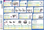
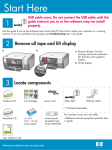
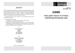
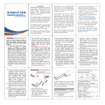
1
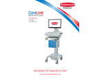
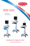
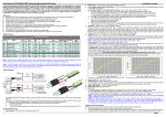
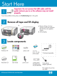
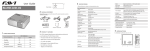
Mobile Technology Cabinet Workstation
User Manual
Warnings
IMPORTANT – Indicates a situation that does not present
any hazard but is very important in maintaining a well
functioning workstation.
ATTENTION – Consult manual to avoid a potentially
hazardous situation which may result in minor or
moderate injury.
• Contact the facility Engineer of Record for direction on mounting
locations and methods prior to installing any wall tracks or
equipment.
• The shipping weight of the nonpowered model is 128 lbs (58 kg).
The shipping weight of the powered model is 156 lbs (70.8 kg).
Use proper lifting techniques to prevent injury.
ELECTRICAL – Indicates an impending electrical hazard
which, if not avoided, may result in personal injury, fire
and/or death.
• The supplied power cord is rated for medical use. Connecting the
cord to an outlet that is not medical grade (indicated with a green
dot) will not ensure grounding protection.
• Power cord and workstation are for INDOOR use only. DO NOT
OPERATE OUTDOORS.
• Keep power cord away from water. DO NOT PLUG CORD INTO
OUTLET IF WET.
• DO NOT OPERATE PRODUCT IF WET. If the WORKSTATION becomes
wet, unplug it immediately, wipe off any excess liquid, and allow it to
dry before using again.
• Inspect power cord before integration. DO NOT USE POWER CORD IF
DAMAGED.
• Fully insert power cord plug into outlet. DO NOT unplug by pulling on
cord. DO NOT remove, bend or modify any metal prongs or pins of
power cord.
• DO NOT use excessive force to make mechanical or electrical
connections.
• DO NOT use an electrical extension cord with your workstation.
• DO NOT use a flammable cleaner on the station as it can result in
fire or explosion.
Transport/Storage
Care should be taken to transport and store this system within a
temperature range of 32ºF to 90ºF (0ºC to 32ºC); Humidity 20% RH to
95% RH non-condensing.
2
Table of Contents
Warnings
2
Box Contents
4
Assembly
5
Install the Cord Holder .......................................................... 5
Install the Power Cord .......................................................... 5
Install the Lithium Battery ..................................................... 6
Integration
8
Component Schematic ......................................................... 8
Specifications ...................................................................... 9
Remove the Rear Panel ........................................................ 10
Open the Keyboard Tray ....................................................... 10
Install the Keyboard ............................................................ 11
Install the Mouse ................................................................ 12
Install the Monitor ................................................................ 13
Replace the Rear Panel ........................................................ 15
Install the CPU ..................................................................... 16
Operation
19
Height Adjustment ............................................................... 19
Open the Keyboard Tray ....................................................... 19
Close the Keyboard Tray ....................................................... 20
Casters ............................................................................... 20
Power Supply Controller ....................................................... 21
Maintenance
22
Install / Change the Battery .................................................. 22
Cleaning.............................................................................. 25
Wood Panel Care ................................................................. 25
Troubleshooting
26
Service
27
Service Request................................................................... 27
Service Level Commitment ................................................... 27
Warranty
27
Limited Warranty for Mobile Technology Cabinet .................... 27
Service Details..................................................................... 27
Box Contents
NONPOWERED MOBILE TECHNOLOGY CABINET
A
x2 B
A
Mobile Technology Cabinet
B
Security Keys
C
Power Cord
D
Cord Holder
E
Lithium Battery *
(Lithium Battery Powered Models only)
Fastened to
Security Panel
C
D
POWERED MOBILE TECHNOLOGY CABINET
A
x2 B
Fastened to
Security Panel
C
4
E
D
* Lithium battery
will be shipped separately.
Assembly
INSTALL THE CORD HOLDER
Choose a location to mount the
Cord holder.
1. Remove paper backing from
cord holder.
2
2. Firmly press the cord holder in
position for few seconds.
Note: The tape to surface bond
will reach 50% strengh 20
minutes after assembly, and 90%
strength after 24 hours.
1
INSTALL THE POWER CORD
1
1. Plug the power cord into the
computer cart.
2. Position the cord lock to secure
the power cord.
Nonpowered
3. Stow the plug in the holder.
2
Powered
5
Assembly
INSTALL THE LITHIUM BATTERY
1. Remove two screws (1) and
the battery cover (2) from the
rear of the mobile technology
cabinet (3).
1
3
2
1
1. Place the battery (10) in the
battery box (4).
2
2. Fasten the battery strap (1).
3. Connect the communication
cables (2).
4. Install a screw (6), lock washer
(7), washer (8) and RED wire
(9) on the positive (+) battery
terminal (11).
2
1
11
+
9
3
10
8
7
6
6
–
4
5
5. Install a screw (6), lock washer
(7), washer (6) and BLACK wire
(5) on the negative (–) battery
terminal (3).
Do Not short the battery across the
terminals. Shorting the battery will cause a
violent reaction which can result in death
or serious personal injury.
Make sure the battery cables are
connected to the correct battery terminal,
connecting the battery cables to the wrong
terminal can cause damage to the power
supply.
Assembly
INSTALL THE LITHIUM BATTERY (CONTINUED)
Install the battery cover (2) and
2 screws (1) on the rear of the
mobile technology cabinet (3).
3
3
2
2
1
1
7
Integration
COMPONENT SCHEMATIC
Power Supply Controller *
Keypad
Monitor
Hand Hold
Mouse
Work Surface
Keyboard
Wrist Rest
Keyboard Tray
Technoloy Cabinet
Power Strip
Security Panel
Locking Caster
Height Adjustment Pedal
* Powered Mobile Technology Cabinet Only
8
Integration
SPECIFICATIONS
Common Specifications
Base Size
Weight
Height Adjustment
Cart Height
Keyboard Height
Front of Monitor to Wrist Rest
Work Surface
Csters
Keyboard Platform
CPU Cavity
LCD Monitor Mount
Power Cord
Power Strip
UPS input
UPS output
Sealed Lead Acid (SLA)
Battery
Lithium Battery
17” x 22” (43.2 cm x 55.9 cm)
Configurations starting at 97 lb (44 kg)
16” (40.5 cm)
44" to 60" (111.8 cm to 152.4 cm)
30" to 46" (76.2 cm to 117 cm)
22" (55.9 cm)
19” w x 11” d (48.3 cm w x 27.9 cm)
4" (10.2 cm) 2 Locking
Accommodates 1.75” H x 18" W x 7.25” D (4.5 cm x 45.7 cm
x 18.4 cm) USB keyboard
19.5" x 10“ x 3.1" (49.5 cm x 25.4 cm x 7.9 cm)
25 lbs (11.3 kg) max. 20" Monitor Max.
2.5 ft (.75 m ) hospital grade spiral cord– extends to 8 ft (2.4
m), recharges on board technologyg, 120/240VAC, 6.3A,
50/60Hz.
3 - NEMA 5/15 outlets with inline fusing
120 Vac 5.0 A
150 VA 150 W
U1-12Vdc 35 Ah
U1-12Vdc 40 Ah
9
Integration
REMOVE THE REAR PANEL
1
Lift and remove the rear panel
to expose the rear of the mobile
technology cabinet.
OPEN THE KEYBOARD TRAY
2
10
Fold down the Keyboard Tray door
as shown.
Integration
INSTALL THE KEYBOARD
1. Remove screws from both sides
of the work surface.
3a
2. Remove the work surface from
the mobile technologh cabinet.
2
1
1. Route the keyboard cable
through the openings in the
undersaide of the worksurface
to the technology cabinet
below.
3b
2. Fasten the keyboard to the
keyboard tray.
Note: Use double stick hook and
loop fastner to fasten the keyboard
to the keyboard tray.
1
2
11
Integration
INSTALL THE KEYBOARD (CONTINUED)
1. Position the work surface on
the keyboard tray.
3c
2. Fasten the work surface (2) to
the keyboard tray with 2
screws (1) .
2
1
INSTALL THE MOUSE
4a
12
• Place the mouse on the work
surface.
• Route the mouse cable
through one of the holes at
the rear of the work surface.
Integration
INSTALL THE MOUSE (CONTINUED)
Route the mouse and keyboard
cables through the opening at the
top of the technology cabinet.
4b
Note: Use cable ties to secure
the cables to the security grid for
strain relief.
INSTALL THE MONITOR
1. Remove the screws (1) from the
bottom of the monitor mount.
5a
2. * Remove the communication
cables from the bottom of the
power supply controller (not
shown).
2
1
3. Lift and pull forward to remove
the monitor mount and Keypad
bracket* assembly (2).
*Powered models only.
13
Integration
INSTALL THE MONITOR (CONTINUED)
5b
• Align the monitor mount,
keypad mount*, and your
monitor.
• Use 4 screws to mount the
monitor mount and keypad
mount* to the monitor.
NOTE: Check your monitor
documentation for mounting screw
size.
*Powered models only.
5c
1. Install the monitor/bracket
assembly on the mobile
technology cart.
2. Install the screws at the bottom
of the monitor mount.
3. * Install the communication
cables on the bottom of the
power supply controller. (The
GRAY cable (com1) on the
LEFT, and the BLACK cable
(com2) on the RIGHT.)
NOTE: If the power will not turn
on the first time you try to turn
the cabinet on, you have the
communication cables crossed.
*Powered models only.
14
Integration
INSTALL THE MONITOR (CONTINUED)
5d
Route the monitor cables through
the opening at the top of the
technology cabinet.
Note: Use cable ties to secure
the cables to the security grid for
strain relief.
REPLACE THE REAR PANEL
• Install the rear panel.
6
• Close the keyboard tray.
Note: Make sure the edges of
the rear panel are installed in the
correct channels.
15
Integration
INSTALL THE CPU
1. Open the Technology Cabinet
Door.
7a
1
2. If necessary, unlock the Security
Panel.
3. Lift,then pull forward to remove
the Security Panel from the
Technology Cabinet.
3
2
7b
16
• Place the CPU into the
Technoloigy Cabinet.
• Make necessary electrical and
cable connections.
Integration
INSTALL THE CPU (CONTINUED)
Insert the top of the Security
Panel into the holes at the top of
the Technology Cabinet.
7c
2
7d
1. Align and lower the bottom of
the Security Panel into the holes
at the bottom of the Technology
Cabinet.
2. Lock the Security Panel.
17
Integration
INSTALL THE CPU (CONTINUED)
7e
18
Close the Technology Cabinet door.
Operation
HEIGHT ADJUSTMENT
1. Use the two handholds to hold
the top of the cabinet steady.
2. Press down and hold the height
adjustment pedal.
3. Raise or lower the cabinet,
then release the pedal.
OPEN THE KEYBOARD TRAY
1
1. Pull down on the keyboard
tray door.
2. Pull down on the door until you
feel and hear the keyboard tray
bump forward.
2
19
Operation
CLOSE THE KEYBOARD TRAY
1. Push the keyboard tray to the
rear until you feel the rear of
the tray lower.
2. Let the keyboard tray close
freely.
1
2
CASTERS
• Lower the tabs to lock the
casters.
• Lift the tabs to unlock the
casters.
20
Operation
POWER SUPPLY CONTROLLER
Power Indicator:
When illuminated indicates the
system is on and power is available
to the PC.
Power Button:
Press the button to turn on the power
supply.
Press and hold the button to turn off the
power supply. The power should only be
turned off if the mobile cabinet will not
be plugged in, or will not be used for an
extended period of time.
Battery Level Indicator:
Battery indicator will sound an alarm
at 20% remaining charge. Plug in
the mobile cabinet immediately.
Mute Button:
Press button to mute the low Battery level
alarm.
When the battery reaches 10% charge
the mute button will no longer work. The
mobile cabinet must be plugged in.
21
Maintenance
INSTALL / CHANGE THE BATTERY
Remove the Battery Cover
1. Remove the power cord from
the mobile cabinet.
1
2. Remove 2 screws( 1) from the
battery cover (2).
3. Remove battery cover (2) from
the mobile technology cabinet
(3).
3
2
2
1
1
Remove the Lithium Battery
1. Disconnect the communication
cables (7).
2
2. Remove 2 screws (4), lock
washers (5), washers (6), and
cables (3) from the battery (1).
3. Unfasten the strap (2).
1
4. Remove the battery (1)
NOTE: Recycle the used battery in
accordance with local laws.
7
3
4
22
5
6
3
2
Maintenance
INSTALL / CHANGE THE BATTERY (CONTINUED)
Install the Lthium Battery
1.Place the battery (10) in the
battery box (4).
3
2. Fasten the battery strap (1).
3.Connect the communication
cables (2).
1
4. Install a screw (6), lock washer
(7), washer (8) and RED wire
(9) on the positive (+) battery
terminal (11).
2
11
3
+
10
9
–
8
7
5. Install a screw (6), lock washer
(7), washer (8) and BLACK wire
(5) on the negative (–) battery
terminal (3).
4
Do Not short the battery across the
terminals. Shorting the battery will cause
a violent reaction which can result in
death or serious personal injury.
5
6
Make sure the battery cables are
connected to the correct battery terminal,
connecting the battery cables to the
wrong terminal can cause damage to the
power supply.
Remove the Sealed Lead Acid (SLA) Battery
1. Remove 2 screws (8), 4
washers (9), 2 cables (1,7),
temperature sensor (6), 2 lock
washers (10), and nuts (11),
from the battery (4).
A2
7
2. Unfasten the strap (2).
3. Remove the battery (4)
6
5
3
4
8
1
2
NOTE: Recycle the used battery in
accordance with local laws.
9
9
10
11
23
Maintenance
INSTALL / CHANGE THE BATTERY (CONTINUED)
Install the Sealed Lead Acid (SLA) Battery
1.Place the battery (4) in the
battery box.
A3
2. Fasten the battery strap (1).
3. Install a screw (8), 2 washers
(9), Lock washer (10), RED wire
(2), and nut (11) on the positive
(+) battery terminal (3).
7
6
1
5
3
4. Install a screw (8), 2 washers
(9), Lock washer (10), BLACK
wire (7), temperature sensor
(6), and nut (11) on the
negative (–) battery terminal (5).
2
4
8
10
9
Do Not short the battery across the
terminals. Shorting the battery will cause
a violent reaction which can result in
serious personal injury.
9
Make sure the battery cables are
connected to the correct battery terminal,
connecting the battery cables to the
wrong terminal can cause damage to the
power supply.
11
Install the Battery Cover
Install the battery cover (2) and
2 screws (1) on the rear of the
mobile technology cabinet (3).
4
3
2
2
1
24
1
Maintenance
DO NOT use the computer cart if
pieces are missing or the unit
is damaged. In these cases, immediately
contact Rubbermaid Customer Service for
more information: 1-888-859-8294.
Cables: Always keep the cables neatly
organized and be sure to route cables away
from moving components with wire ties or
cable clips.
Electric Cables: Periodically inspect power
cord and plug to ensure plug is not bent and
cable is not frayed.
CLEANING
CAUTION: Because of the close
proximity of electrical power and
equipment, flammable cleaners should never
be used on the computer cart.
• Verify that your computer cart is unplugged
from the wall outlet before cleaning.
• Remove pen and dry erase marker stains
with a soft cloth and 91% isopropyl alcohol.
• Remove iodine stains with a soft cloth and
any cleaners suggested above.
DO NOT use the following
chemicals to clean your computer
cart: acetone, mineral spirits, abrasive
cleansers, paint thinner or any other harsh or
toxic chemicals.
WOOD PANEL CARE
•Harsh, abrasive and undiluted cleaning
products may cause damage to Deco Lam
and the contact adhesive.
Pine Sol and Simple Green are cleaners that
have been approved for use on Deco Lam.
A 30-1 ratio of water to cleaner is highly
advised. Recommend water and a clean towel
as a cleaning alternative to homeowners.
• Allow your computer cart to dry completely
before plugging the power cord into a wall
outlet.
• When cleaning the computer cart, wipe
surface with a damp cloth and thoroughly
dry.
• NEVER cover the computer cart or its
components with liquid or allow liquids to
flow into the computer cart.
• NEVER use steel wool or other abrasive
material as these could damage the surface
finish.
• Before using any cleaner on the computer
cart, first test on a small area to ensure that
the surface is not harmed.
• These guidelines cannot guarantee infection
control. The hospital’s Infection Control
Administrator should be consulted regarding
cleaning procedures and schedules.
• Clean plastic components with diluted,
non-abrasive solutions. Suggested cleaners
are water, soap, diluted bleach and alcohol
solutions.
25
Troubleshooting
Problem
Cart Is Hard To Push.
Solution
Check that the caster locks are in the unlocked (up) position.
Check casters for obstructions.
Computer/Monitor will
not power up.
Check that power supply is turned on.
Check that device power cables are connected.
Check that wall outlet has power.
Check fuses at cabinet power inlet.
Power supply does not
turn on.
Check power cord.
Check that wall outlet has power.
Check fuses at cabinet power inlet.
REVISION HISTORY
Revision
26
Date
Description of Changes
A
06/2011
Initial Release
B
02/2013
Change Logos and text references to Healthcare
Add revision history table
Service
SERVICE REQUEST
Please visit our website at: www.rubbermaidhealthcare.com/service to file a request for parts.
SERVICE LEVEL COMMITMENT
Rubbermaid Healthcare is committed to providing best-in-class service. This document details
our standard warranty and instructions on how to request service using our customer support
system.
Warranty
LIMITED WARRANTY FOR MOBILE TECHNOLOGY CABINET
Rubbermaid Healthcare is pleased to offer a three-year warranty on durable components and a
two-year warranty on electronic components.
If during the warranty period this Rubbermaid Healthcare product proves defective in materials
or workmanship under normal use by the original purchaser, please contact Rubbermaid
Healthcare technical support at www.rubbermaidhealthcare.com/service (please be sure to
complete all information, including product serial number, description of the issue, and full
contact information). Rubbermaid Healthcare will determine, at its sole discretion, how to best
address your warranty issue, which may include sending you a replacement part covered
under warranty or for sale. Rubbermaid Healthcare reserves the right to require proof-ofpurchase prior to honoring any warranty request. This warranty does not cover product
abuse, modification, failure to adhere to product instructions, or improper operation/misuse.
Rubbermaid Healthcare SHALL NOT BE LIABLE FOR ANY CONSEQUENTIAL OR INCIDENTAL
DAMAGES WHATSOEVER. Some states do not allow the exclusion or limitation of incidental or
consequential damages, so the above limitation or exclusion may not apply to you. This warranty
gives you specific legal rights and you may also have other rights which vary from state to state
or country to country.
SERVICE DETAILS
Consumable components are not covered under warranty and include:
• Locks and Keys
All other standard components will be replaced under the applicable warranty following a filed
service request. If the service request is received prior to 10 am EST, replacement parts will
ship next business day. Requests filed after 10 am EST will be fulfilled with parts shipped in 2
business days. All replacement parts will ship via ground carrier.
*The above terms for replacement parts applies to facilities located in the United States. All
other customers should contact the appropriate reseller for the terms of part replacement.
27
1-888-859-8294
www.RubbermaidHealthcare.com
02/2012 Part # 1829683 REV B MOBILE TECHNOLOGY CABINET WORKSTATION USER MANUAL
© Rubbermaid Healthcare
Huntersville, NC 28078