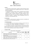
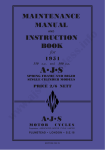
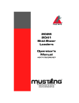
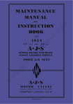
1
THE LIGHTWEIGHT ENGINE.
A Technical Analysis by John Allen
Introduction
This note gives general details on the post-war AMC lightweight engines which were used
in AJS 14 and 8 models and Matchless G2 and G5 models. It covers all models.
The 250cc AJS 14 and Matchless G2 were introduced in the early summer of 1958 to
complement AMC's existing range of bikes. They were better than most of the 250cc machines
available but suffered from a weak engine bottom end and poor telescopic front forks. Although
not particularly light, they were called 'Lightweights.' During 1960, 1961 and 1962, 350cc models
(the 8 and G5) were sold with a stronger crankpin, duplex primary chain and 1 I/8 inch diameter
'Teledraulic' forks. Similarly, sports and scrambler versions of the 250cc models, the 14S and G2S
and 14CS and G2CS, were sold. 250cc CSR models were built with Teledraulic forks, a more
substantial crankpin and duplex primary chain, and became available in the summer of 1962,
remaining in production until the demise of AMC in the late summer of 1966. The 250cc engine
has ten fins on the barrel while the 350cc has twelve.
The Lightweight models have suffered from a ‘poor relation’ attitude, being used by either
those who could not get a Heavyweight single or a twin or those who were simply masochistic.
This isn't fair. They remain an affordable introduction to the marques and can be made to go
reliably and quickly. For the smaller models, the later ones are better (try to avoid the ghastly
Francis-Barnett forks).
ManuaIs and parts lists
Bruce Main-Smith Ltd, 1 Featherby Drive, Glen Parva, Leicester LE2 9NZ, can supply
photocopies of instruction manuals and parts lists for most models. However, they were not
published yearly and it appears that there are no parts lists for 250cc models after 1962. The
instruction manuals were quite comprehensive but did not give details about work on the bottom
end of the engine.
Lodgemark Press publishes a manual, written by an ex-service manager at AMC - Fred
Neill, with details of the post-1963 engines. This covers all post-1956 singles (both Heavyweight
and Lightweight but it does contain some mistakes, although usually these are obvious. The main
problem with it is that its layout is extremely poor and there is no index. I believe that it can be
obtained from the Spares Scheme.
At autojumbles, you may find a true AMC service manual, about A4 size with a red cover.
This is essentially the same as the Lodgemark book, although some do not have details of later
250cc CSR models.
Roy Bacon has written a couple of books about AMC models. These have some very good
pictures, are better written than Neill's works and have some, at least, of the errors corrected.
However, I feel that they do not go to such a depth as Neill's books (I would not rely on them when
building an engine, for example).
Haycraft's book, in the Pitman series, has no information on Lightweights whatsoever,
although there is a picture of one on the cover.
Historical summary
When introduced in May 1958 the main features of the 250cc light-weight engine were:
o Unit-construction appearance with the gearbox apparently integral with the engine castings
(it was not, the gearbox, clutch and primary drive were hidden by bulbous side casings).
o Offset (or désaxé cast iron cylinder (to reduce wear) with a bore and stroke of 69.85mm
and 64.84mm.
o Oil tank bolted on to the timing side crankcase with a felt oil filter in the drive side crankcase
(dry sump). No external oil pipes.
o Crankshaft supported by two ball bearings, with a timed crankcase breather between them,
in the drive side crankcase, and a bronze bush for the timing side bearing.
o Reciprocating plunger oil pump driven by a worm on the timing side axle (similar to the
heavy-weight single engine).
o Single camshaft, carrying two cams, driven from timing pinion on timing side axle. The nose
of the camshaft drove the ignition contact breaker through a centrifugal advance and retard
mechanism.
o Pushrods, enclosed in the barrel casting, activated by pivoted cam followers.
o Wire wound piston.
o Cylinder head and rocker box similar to the Heavyweight single with hair pin valve springs.
However the head was rotated 21° compared with the crankshaft. The head had secondary
finning to encourage air over the spark plug.
o Ignition was from a coil with an alternator providing the electricity.
Changes:
o 1960 [350cc Light-weight introduced with a bore and stroke of 72mm and 85.5mm,
duplex primary chain].
o 1962 - New clutch and chaincase introduced in December 1961 (after engine number
c11500).
o Hard chromed cam followers used on engines after engine number 12128 (including
CSRs).
o CSRs introduced in May (engine numbers 12128 to 12673). These had steel
flywheels, large diameter crankpin, larger inlet valve, new timing side covers and
chaincases, a repositioned oil hole in the timing chest and a duplex primary chain.
o
1963 [Only the CSRs remained in production] (engine numbers from 12828)
o Long stroke oil pump fitted with direct feed to cam followers.
o Change in crankcase oil ways.
o Oil metering plugs deleted from rocker box.
o 1965 (engine numbers from 13965)
o High compression pistons fitted, ignition timing 24 degrees BTDC (advanced).
o Coil valve springs with collars to suit.
o Oil control screw in cylinder head deleted.
o
1966 (engine numbers from 14757 to 15506)
o Ignition timing 27 degrees BTDC (advanced 1 ).
o Low compression piston offered using a timing of 34 degrees BTDC (advanced).
o Direct oil feed to cam followers deleted.
The 250 CSRs. This is a 1963 AJS 14CSR, with distinctive tank, Teledraulic forks and
chromed steel mudguards. (photo: Tony Head)
This is a final year's Matchless G2CSR (toting a supply of 'Watson's' Matchless Cleaner!).
Note the alloy guards - the silencer and badging are not standard, but the rest is. And very
nice it is too
Potential problems
Crankpin -The early engines suffered from crankpin breakages. AMC redesigned the
crankpin and conrod a number of times and the final large diameter pin is available as a pattern
part from Alpha Bearings to order - if you can get a late conrod.
Crankcases are interchangeable between early and late models. However, the chaincase
was wider on duplex primary chain models. The alternator was also set further into this chaincase.
The main bearing arrangement which used two ball bearings had a short life. The inboard
bearing, next to the drive side flywheel, should be replaced by a roller bearing. This will also ease
assembly.
Valve gear wear - The contact between the hairpin valve spring and collar wears, and to a
much lesser extent the spring tangs and valve spring tray.
Inlet valve sticking - Carbon from the valve stem oiling can stop the valve from closing.
This sticking is often a problem if the bike has not been used for some time.
Piston cracking - Pistons can crack either across the dome or around the top ring groove.
This is usually associated with pattern pistons and a large right hand. Less serious, in the short
term, is skirt cracking from expansion slots on some pattern pistons.
Automatic advance and retard unit - This was a Wipac part and appears to be more
robust than its Lucas equivalent. However, there is no way of lubricating it. They can break up. A
special tool is needed to remove it.
Rocker box gasket - Some pattern gaskets destroy themselves due to the movement
between head and rocker box.
Cast iron exhaust valve seats can become loose; later engines used bronze seats. Likewise
the exhaust valve guide can work loose since it is too short for the job.
Pattern cylinder head gaskets can give problems; use copper ones instead.
Oil pump - The oil pump is almost foolproof. However, the long stroke oil pump cannot be
fitted to early engines.
The engine can suffer from bad oil leaks. Porous castings have been blamed, particularly
for barrel oil leaks. However, before going to the bother of sleeving the oil passage to the cylinder
head check that the small breather hole between the oil tank to the crankcase cavity is not
blocked.
EXPLODED VIEW OF MATCHLESS & A.J.S. 250 cc & 350 cc - OVERHEAD VALVE ENGINE
(Transcriber’s note: as per spares list / parts list / Neill / etc.)
Availability of parts
Very, very few of the parts used in the lightweight engine and gearbox were interchangeable with
heavyweight parts. Rocker box bolts and a main bearing are common.
Most wearing engine parts are readily available from either the Club Spares Scheme or the
London shops. However, do not expect them to be cheaper than other new parts. The 250cc
piston had either a circular or steeply ramped crown while the 350cc one was flat. Over-weight
pistons should be avoided since the loads on the crankpin are increased, giving a short crankpin
life, and vibration will be worse. On the 350cc engine, an AMC 600cc piston can be used. This will
give a higher compression ratio.
Castings are very easy to obtain. The crankcases must match and the threads for the oil
filler cap and oil filter should be in good condition. This also applies to the internal oil tank.
The 250cc CSR cylinder head will fit the 350cc engine.
The CSR exhaust valve is noticeably small. However, its stem diameter is 8.5mm compared
with the standard exhaust valve diameter of 8mm. The inlet valve has a 7mm diameter stem.
The coil ignition automatic advance and retard units are no longer available and you are
very unlikely to find a good one. This is a major problem. The options seem to be:
Fix the unit to one position and time the ignition to fully advanced or slightly retarded and
accept that the engine may kick back during starting.
Convert the electrics to 12 volts and use an electronic ignition system that incorporates an
advance and retard operation.
Dismantling and assembly advice
NB Any work should be done using an instruction manual. All you have here is advice.
The bottom channel of the frame is removed with the engine. Since it carries the centre
stand do not take the engine and gearbox assembly out of the frame with the bike on the centre
stand. Either stand the bike on blocks instead of the stand or make sure it is kept upright by rope
from the handlebars to the ceiling of the workshop. The frame should be lifted clear of the bottom
channel, engine and gearbox. There are six screws securing the rear portion of the chaincase (not
three as in Neill).
The plunger oil pump must be removed before separating the crankcases. Occasionally
difficulty is experienced in removing the plunger after the guide pin is removed. It has to be pushed
towards the rear of the engine. Usually it can be pulled out using the end of a spoke, but if
necessary, use a bolt (bearing against the front casting wall), nut and sleeve to push it out, see
sketch (A below).
Sketch A
The timing pinion must also be removed before separating the crankcases.
Before the main bearings can be drifted out of the crankcases, the peening next to the
inboard bearing (usually just the outer race of a roller bearing) must be removed. The screw
holding the breather stator must also be removed. On some engines, this was incorporated with
the breather pipe. Uniformly heat the casing and remove the assembly by using a drift on the ball
bearing inner race (this may be difficult on some engines, if so use a drift with a shoulder that sits
well in the ball bearing inner race). (Sketch B below)
Sketch B
If there is a flat on the oil pump plunger guide pin it must be replaced.
Check that all the oil passages in both crankcases, barrel and cylinder head are not
blocked. Also see that the small breather hole from the oil tank to crankcase cavity is clear (I have
heard of the factory failing to drill this hole). It is right at the top of the tank by the filler cap.
All parts must be clean before assembly. Rubbing parts, bearings and gears must be well
lubricated. Use clean engine oil or, if the engine is going to stand for some time before use, a high
quality anti-scuffing paste.
The crankcases are matching pairs and are dowelled together. If there is a step between
the cases at the mouth of the cylinder or the hole for the cylinder spigot is mismatched, you have
problems. The former can be machined flat, but it would be wiser to look for another pair of
crankcases in both cases.
The early engines used two ball bearings as drive side main bearings; how these were
assembled with the crankshaft and drive side casing is a mystery. The inboard bearing should be
replaced by a roller bearing, thus allowing the outer race to be fitted with the outboard ball bearing
and breather stator. The race should be peened into the crankcase in three positions. The
crankshaft with the drive side axle carrying the breather rotor (keyed to the axle) and the rest of
the roller bearing can then be fitted into the crankcase.
The crankshaft end float, without the alternator fitted, must be greater than 0.020 inch. If it
is not the inside face of the timing side bush must be machined or ground back. If there is end float
with the alternator fitted and tight first check that the engine sprocket is fitted the correct way
round. If so, the main bearings are loose in the drive side crankcase. This can be cured by
Loctiting the outer races of the main bearings into the casing or sleeving the casing to give the
correct bore for the bearings. If the crank is absolutely tight and cannot be rotated the breather
rotor has probably been left out.
When assembling the oil pump, check that the guide pin has successfully engaged the
plunger.
If new piston rings are fitted the glaze on the cylinder bore should be lightly removed by
emery paper. A proprietary emery flap wheel is sold for this purpose. The wear step at the top of
the bore should be removed or at least blended out.
The piston has cut-aways for the valves which are of different sizes. The small cut-away, for
the exhaust valve, must face forward.
Make sure that the small oil feed hole on top of the cylinder head, between push rods, is not
masked by the rocker box gasket.
The screw which controls the supply of oil to the inlet valve guide should only be a third of a
turn open. Later heads do not have this screw.
Cut the sealing rubber for the tappet inspection cover to the correct length and join the ends
to make a ring using superglue.
The sparking plug should be a Champion N5, Bosch W8CC or NGK B7ES. It is probably
unwise to use an N9Y as an equivalent to an N5. 1965 /1966 engines used a Champion N3 plug.
Bolt torques
Big end nuts – 190 ft.lbf (140ft.lbf on early cast iron flywheels).
Cylinder head bolts – 35 ft.lbf.
Rocker box bolts - 10.5 ft.lbf (with both valves closed).
The bolts should be tightened in stages with the torque settings increasing until reaching
the above values. Both cylinder head and rocker box bolts must be tightened down in a diagonal
sequence. The service sheets do not say if the threads should be lubricated but they must be
clean.
Valve timings
It is worth noting that when the piston is at one top dead centre, both valves should be
closed. At the next both should be slightly open with the exhaust about to close and the inlet
opening. The engine will run if this is the case, even if the valve timings are out.
Since there is only a single camshaft, timing is easy; just line up the dot on the cam wheel
with the one on the timing pinion. The piston should be at the top of its stroke (top dead centre) at
this position.
Tappet adjustment
Note, feeler gauges are not required. The tappet adjustment must be done with both valves
closed and the engine warm.
Take off the inspection cover on the rocker box.
At the top of the push rod, undo the locking nut and screw the end cup out until it is finger
tight.
Do up the lock nut and you should just be able to rotate the push rod with your fingers.
Repeat for the other push rod.
Ignition timing
The contact breaker gap, fully open, should be 0.012 inch.
The timing must be set for the fully advanced position. The timings are as follows:
250cc (up to 1964) and 350cc - 34° - 1/4 (0.267) inches before top dead centre
250cc (1964) - 24° - 3/16 (0.136) inches before top dead centre
250cc (1966) - 27° - 3/16 (0.171) inches before top dead centre
The fraction measurements are quoted in the handbook while those in brackets are
calculated from the angle.
If a low compression piston is fitted to a late engine the early 250cc timing should be used.
A timing disc can be used, and may be more accurate, but it involves removing the outer
primary chaincase which is always a pain. Therefore, the details are solely for the spoke-throughthe-spark-plug-hole method.
1.
Remove the contact breaker cover. Disconnect the wire to the contact breaker and
remove the contact breaker carrying plate.
2.
Remove the spark plug, and with the rear wheel off the ground select top gear.
3.
Put a thumb over the spark plug hole and rotate the rear wheel forwards,
anticlockwise, looking from the left hand side of the bike until you feel the cylinder
pressure lifting your thumb off the cylinder head.
4.
Take an old spoke and bend it so that it cannot drop into the cylinder. Hold it as near
vertical as possible and rotate the rear wheel forwards, then, just rocking the wheel,
set the piston at the top of the cylinder (top dead centre).
5.
Make a mark with a spirit based pen on the spoke that lines up with a feature on the
cylinder head.
6.
Remove the spoke and scratch a permanent mark on the pen mark using the edge of
a file.
7.
Lightly scratch a second mark the required distance from the first away from the end
that went into the cylinder. Check the distance and correct it by adjusting the
direction of cut of the file.
8.
Check the top dead centre position of the piston and then rotate the rear wheel
backwards, clockwise from the left side, until the top mark on the spoke lines up with
your chosen feature on the cylinder head.
9.
At this position, an imaginary line through the gaps between the bob weights of the
advance and retard mechanism should point at the anticlockwise faces of the screw
bosses for the contact breaker plate (see sketch below). The lobe of the contact
breaker cam should be pointing downwards. If it is not pull the mechanism off the
camshaft and reset the position. If you have repositioned the advance and retard
mechanism, check that the piston is still at the correct position.
10.
Refit the contact breaker plate so that the contacts are just open. Nip up the screws
holding the plate.
11.
•
Insert a clean 0.0015inch feeler gauge (the thinnest in a feeler gauge set)
between the contacts.
•
Using a screwdriver through the hole in the contact breaker plate separate the
bob weights to get the maximum advanced position. If the timing is correct, the
feeler gauge should just be free.
•
If the feeler gauge is not, scratch a mark that crosses from the plate to the
surrounding casting.
•
Loosen the screws, rotate the plate a fraction (clockwise if. the feeler gauge was
loose, anticlockwise if tight) and then tighten. Insert the feeler gauge between the
contact breakers and repeat the process until the feeler gauge is just free.
Tighten everything and recheck before reconnecting the wire, fitting the spark plug
and replacing the cover with its gasket.
An electrical continuity test can be used instead of the feeler gauge.
Carburation
Since I intend to deal with carburettors in detail in a later article, I will not give a lot of details
about jets, etc. In practice, if the carburettor is in good condition there should be no reason to alter
the jets and the slide from the values given in the manual.
If the main body of the carb is heavily worn, that is if a new slide can rattle around when it is
at the bottom of its travel, it is well worth getting the body sleeved.
The heat insulating block between the cylinder head and carburettor should be in good
condition and not have any cracks in it. An O-ring should be used in the flange if there is a groove
for one. If it is the gasket can be dispensed with. The nuts on the carburettor studs should not be
done up very tight.
If a Concentric has been fitted instead of a Monobloc the main jet should be reduced in size
by 30.
Oil capacities
The engine oil capacity is small, about two and a half pints. Since the oil remains hot in the
engine it should be changed frequently - every 2000 miles or less. Before topping up, run the
engine to scavenge the crankcase.
The gear clusters are at the top of the gearbox; the ‘box really does need three pints.
Special tools
Timing pinion puller (043332), a sprocket puller cannot be used.
Bolt for removing advance/retard mechanism (042247).
Hairpin valve spring tool (018276).
Car-type valve spring compressor for coil springs.
This (unsurprisingly, perhaps) is a very late 250CSR, of the type which has
been causing such a commotion in the Letters pages. It should have a
cigar-shaped silencer...
Many of the early 250 lightweight's shortcomings were answered when AMC
introduced the 350s. Sadly, they were in production for only two years. This is
the AJS Model 8 which won the Lightweight Concours at the'89 Jampot Rally.
It belongs to Paul Hinert
Lightweight singles rarely command high prices, so when buying them it pays
to be careful, checking that what you buy is what is advertised. This AJS, for
instance, is a 350 Model 8, but it clearly wears a 250 front end...
And, to close John Allen's fine series, here is a lightweight single of a different
. style entirely. AJS 2-strokes are still largely unloved, and still largely
under-valued. And who cares whether they are indeed 'real' Ajays; they're fast,
they're fun, and they're affordable! Buy now...